1
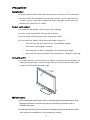
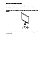
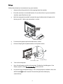
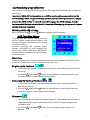
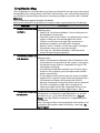
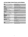
F-419
19" TFT LCD PANEL
Table of Content
Precautions ................................................................................................................................. 2
Installation................................................................................................................................................ 2
Power connection ................................................................................................................................... 2
Using the Tilt ............................................................................................................................................ 2
Maintenance ............................................................................................................................................ 2
Transporting the monitor.................................................................................................................... 3
Getting Started .......................................................................................................................... 3
Package contents .................................................................................................................................... 3
Installing and Removing the Base.....................................................................................................4
Identifying parts and controls............................................................................................................ 5
Setup...........................................................................................................................................................6
Customizing your Monitor ...................................................................................................... 8
Working with OSD Groups...................................................................................................................8
Brightness & Contrast .........................................................................................................................8
Horizontal & Vertical Position............................................................................................................8
Sharpness..................................................................................................................................................8
OSD Transparency ..................................................................................................................................9
Phase & Clock...........................................................................................................................................9
Auto and Input Select............................................................................................................................9
Horizontal & Vertical OSD Position .................................................................................................9
Mode Text/Graphics ............................................................................................................................9
Recall ........................................................................................................................................................9
Selecting a Language.............................................................................................................................9
Selecting a Color Temperature setting ..........................................................................................10
Exit ............................................................................................................................................................10
Troubleshooting........................................................................................................................ 11
LCD Panel Display Technical Features and Specifications................................................12
Interface Frequency..................................................................................................................13
Supported Timing List ............................................................................................................ 14
Regulations ............................................................................................................................... 16
FCC compliance ..................................................................................................................................... 16
TCO'99 .......................................................................................................................................................17
Precautions
Installation
• Do not cover or block the ventilation ports on the rear of the monitor.
• Do not install the monitor close to heat sources such as radiators or
air ducts, or in a location exposed to direct sunlight, excessive dust,
mechanical vibration, or shock.
Power connection
• Use the correct power cord for your local voltage.
• Use an accessible outlet close to the monitor.
• Do not allow anything to rest on the power cable.
• Disconnect the power cable from the power supply if:
o
You will not use the monitor for an extended period.
o
The cable is damaged or frayed.
o
The monitor has been dropped or the cabinet damaged.
o
A distinct change in performance indicates a need for servicing.
Using the Tilt
• Use the monitor’s tilt capability to adjust its vertical orientation to an
appropriate position. Grasp the top corners of the monitor with both
hands and tilt to the desired angle.
+20
0
Maintenance
• Clean the cabinet and controls with a soft cloth lightly moistened with a mild
detergent solution. Do not use any abrasive materials or solvents such as
alcohol or benzene.
• Do not rub, touch, or tap the surface of the screen with sharp or abrasive items
such as pens or screwdrivers, as the screen may scratch.
2
• Do not insert objects or spill liquids into the ventilation ports on the monitor’s
rear, as fire, electric shock, and/or unit failure may result.
Transporting the monitor
When transporting the monitor for repair or shipment, use the original carton and
packing materials.
Getting Started
Package contents
Before beginning, ensure that the carton contains the following items:
• Monitor
• Base
• Power cord
• Signal Cable
Analog: D-SUB Cable
Digital: DVI Cable
• Floppy/CD-ROM containing Windows ® information file
• This manual
3
Installing and Removing the Base
To attach the base to the monitor, do the following:
When you open the packing carton, remove the LCD monitor base, and place it on a desk
or table. Then attach the LCD monitor to the base.
Note: Make sure that the monitor’s base pegs and the base stand are firmly locked
together.
To remove the base, turn the monitor on its side or up-side down, push the pegs to lift
base off monitor.
4
Identifying parts and controls
The center front panel of the monitor carries the control array.
FRONT VIEW
The controls are, from left to right:
AUTO button
Automatically adjusts the picture and performance. The AUTO function should
be used the first time you use the monitor and after changing the resolution
and/or refresh rate of the input signal.
Note: 1) It must be pressing the AUTO button over 1 second to execute auto adjustment.
2) If the OSD is acting, this key function will same as down button.
UP button
Navigates within the display
DOWN button
Navigates within the display
LEFT button
Activates the OSD and navigates within the display
RIGHT button
Activates the OSD and navigates within the display
LED indicator
Indicates the monitor’s operational mode; green for regular operation, and
amber for power saving mode.
Power switch
Turns the monitor on and off
5
Setup
Follow these directions to correctly set up your monitor.
1.
Remove all packing materials and wrapping from the monitor
2.
Place the monitor in its desired location. Ensure that there is space around the
monitor, especially the rear area.
3.
With the computer turned off, connect the signal cable to the VGA port or DVI
Port on your PC. Make sure connection is secure.
DVI Port
VGA Port
Video Connector
4.
To connect the power cord to the Monitor AC socket.
5.
Connect the plug Pin of power cord to an AC power source.
AC Power Jack
6.
7.
Power Cord
Turn on the computer.
Press the soft power switch on the monitor. The display should appear. If no
display appears, check Troubleshooting in this manual.
8.
Ensure that your computer display is set at 1024X768 pixels and 60Hz. Press the
AUTO button
exceed 1 second. The monitor optimizes the display
automatically.
6
Note: The monitor is compliant with VESA FPMPMI standards and can be wall- or
arm-mounted. Before wall-mounting or arm-mounting, please disassemble the
monitor stand first.
9.
Unscrew screws of the hinge bracket
10.
Remove the stand from LCD monitor
1
2
11.
The rear of this LCD display has four integrated 4 mm, 0.7 pitches threaded nuts,
as well as four 5 mm access holes in the plastic covering as illustrated below.
These specifications meet the VESA Flat Panel Monitor Physical Mounting
Interface Standard (paragraphs 2.1 and 2.1.3, version 1, dated 13 November 1997).
100mm x 100mm
Screw Mounting Options
100mm
100mm
4mm ,0.7pitch threaded holes x4
7
Customizing your Monitor
The On Screen Display (OSD) system provides a full range of customizable tools to optimize
your display.
Important: While full customization is available, we strongly recommend using the
AUTO settings, which are preset to fully optimize your monitor’s performance. Simply
presses the AUTO button
exceed 1 second to engage the AUTO settings. It is also
recommended that you execute the AUTO function following any change made to your
display from your computer.
Working with OSD Groups
Press any of the LEFT
, or RIGHT
buttons to open the OSD window.
OSD Function Menu
To access OSD Main menu, simply press one
of the Function Select control buttons, and
the menu diagram will pop up on the screen
as shown on Fig. 1-1:
Continue pressing the Function Select
buttons (left/right) to scroll through the
entire menu items ,then press Adjustment
Control buttons (up/down) to adjust content
of selected item.
Attention
Firmware revision may have been updated into a latest version while the version number
shown on all OSD menus in this manual will stay as Ver. 1.00.
Brightness & Contrast
/
1. To fine-tune the monitor’s brightness and contrast, select the pertinent item from
the menu.
2. Use the UP
and DOWN
buttons to set the display as desired on the 0-100
scales that appears at the bottom of the window.
Horizontal & Vertical Position
/
1. To fine-tune the display’s position on the monitor screen, select the pertinent
item from the menu.
2. Use the UP
and DOWN
buttons to set the display as desired on the 0-100
scales that appears at the bottom of the window.
Sharpness
1. This function let's you select the images sharpness. Five selections are available. A
smoother setting is more suitable for pictures, while a sharper setting is more
suitable for text.
2. Use the UP
and DOWN
buttons to set the display image sharpness as
desired.
8
OSD Transparency
1. This function let's you set the transparency of the OSD menu. The transparency is
adjustable from 0 to 10. 11 scales are available.
2. Use the UP
and DOWN
buttons to set the transparency of OSD manu as
desired.
/
Phase & Clock
1. To fine tune picture performance to compensate for drifts in the computer signal,
select the pertinent item from the menu.
2. Use the UP
and DOWN
buttons to set the display as desired that appears at
the bottom of the window.
Auto and Input Select
1. To enable the monitor’s Auto Adjust capability, select Auto Adjust from the menu.
2. Use the DOWN
button to toggle Auto Adjustment, use Analog Input and use
Digital Input.
3. Use the UP
button to run selecting function.
Horizontal & Vertical OSD Position
/
1. To position the OSD window to your preference, select OSD Position from the
menu.
2. Use the UP
and DOWN
buttons to move the display through its available
positions.
Mode Text/Graphics
1. To choose between the monitor’s automatic Sharpness optimization for Text or
Graphic use, select Mode Text/Graphic from the menu.
2. Use the UP
and DOWN
buttons to toggle between TEXT and GRAPHIC as
desired at the bottom of the window.
Note: For better performance, please change to “Text” mode when display resolution is set
at 720 x 400 and change to “Graphics” mode when display resolution is set to 640 x 400.
Recall
1. To return the monitor’s settings to the factory default, select Recall from the
menu.
2. Use the UP
and DOWN
buttons to toggle between YES and NO as desired at
the bottom of the window.
Selecting a Language
1. To select the language in which you wish the OSD to appear, select Language from
the menu.
2. Use the UP
and DOWN
buttons to toggle through the available languages
shown at the bottom of the window.
9
Selecting a Color Temperature setting
The following conditions are recommended for the available settings:
Setting
Use
9300K
General Use
6500K
Color Management
USER
User color setting
Auto Color
Auto adjust to best ADC gain value.
1. Select the desired setting from the menu.
2. Selecting a User-Defined Color Balance Setting.
3. You can fine-tune the red/green/blue picture settings according to your
preference or specific application.
4. Select the pertinent color category from the menu.
5. Use the UP
and DOWN
buttons to set the display as desired on the 0-100
scale or run auto color adjust function when select to auto color function.
Exit
Select EXIT from the menu to exit the OSD menu.
10
Troubleshooting
This LCD Monitor has pre-adjusted using factory standard VGA timings. Due to the output
timing differences among various VGA cards in the market, users may initially experience
an unstable or unclear display whenever a new display mode or new VGA card is selected.
Attention
This LCD Monitor Supports Multiple VGA Modes.
Refer to the Standard Timing Table for a listing of modes supported by this LCD Monitor.
PROBLEM
Check Items
•
Picture is unclear and The picture is unclear and unstable, please perform the
following steps:
unstable
1. Enter PC to “Shut Down Windows” status while you’re in
MS-Windows environment.
2. Check the screen to see if there’s any black vertical stripes
appear. If there are, take advantage of the “Clock”
function in OSD menu and adjust (by increment or
decrement numbers) until those bars disappear.
3. Move to “Phase” function in OSD menu again and adjust
the monitor screen to its most clear display.
4. Click “No” on “Shut Down Windows” and back to the
normal PC operating environment.
• There is no picture on If there’s no picture on the LCD Monitor, please perform the
following steps:
LCD Monitor
1. Make sure the power indicator on the LCD Monitor is ON,
all connections are secured, and the system is running on
the correct timing. Refer to “Supported Timing List” for
information on timing.
2. Turn off the LCD Monitor and then turn it back on again.
If there is still no picture, press the Adjustment Control
button several times.
3. If step 2 doesn’t work, connect your PC system to another
external CRT. If your PC system Functions properly with a
CRT Monitor but it does not function with the LCD
Monitor, the output timing of the VGA card may be out of
the LCD’s synchronous range. Please change to an
alternative mode listed in the Supported Timing List or
replace the VGA card, and then repeat steps 1 and 2.
• There is no picture on If you have chosen an output timing that is outside of the
LCD Monitor’s synchronous range (Horizontal: 24 ~ 80 KHz
LCD Monitor
and Vertical: 49 ~ 75 Hz), the OSD will display a “Out of
Range” message. Choose a mode that is supported by your
LCD Monitor.
Also, if the signal cable is not connected to LCD monitor at all
or properly, the monitor screen will display a message “No
Input Signal”.
11
LCD Panel Display Technical Features and Specifications
Panel
Monitor
Input Signal
Compatibility
Connector
Tilt
Dimensions
(W x H x D)
Weight
Screen Size
19" (48cm) diagonal
Pixel Format
1280 x 1024 vertical strip
Display Colors
16.7M with FRC or Dithering
Frequency
Horizontal: 24kHz - 80kHz, Vertical: 49Hz - 75Hz
Max. Pixel Clock
135MHz
PC
Max to 1280 x 1024 @ 75Hz
Analog
15-Pin Mini D-Sub
Digital
24 – Pin DVI
Power
3-Pin AC Inlet
Tilt Angle
0º - +20º
Net
422 x 410.5 x 220mm (16.6" x 16.1" x8.7")
Net
6.5Kg (14.3lb)
Safety
Regulations
UL/CUL, EPA, CB, TUV/GS, Nordic, NUTEK, TCO99,
ISO 13406-2
EMI
FCC, CE, BSMI, VCCI
VESA
DDC1/2B, DPMS
AC
100 ~ 240V, 50 /60Hz
Power
Consumption
<50 Watts (On), < 3 Watts (Stand-by), < 3 Watts
(Suspend), 3 Watts (Off)
12
Interface Frequency
The following frequency range is the working period. If the entered mode between below
period but not match the frequency of supported timing, display optimization not be
assured. If the entered mode is out of the working period, the display will be blanking
(just show “out of range”) then go to power saving.
Basically, mode judgment is regardless the sync polarity except both or more modes that
are all belong to the supported timing list and could be judged by sync polarity only.
At the meantime, real entered frequency of the supported timing is not requested exactly.
Normalization of VGA card’s deviation will be acceptable.
•
Horizontal Frequency
24KHz ----80KHz
•
Vertical Frequency
49Hz ------75Hz
13
Supported Timing List
If the selected timing is NOT included in table below, this LCD monitor will use the most
suitable available timing.
TIMING
640x350
VGA-350
640x350
AIC-350-50Hz
640x350
AIC-350-60Hz
640x400
AIC-400-50Hz
640x400
AIC-400-60Hz
640x400
NEC PC9801
640x400
VGA-GRAPH
640x400
NEC PC9821
640X480
VESA-PAL
640x480
VGA-480
640x480
APPLE MAC-480
640x480
VESA-480-72Hz
640x480
VESA-480-75Hz
720x400
VGA-400-TEXT
720x400
AIC-400-50Hz
720x400
AIC-400-60Hz
832x624
APPLE MAC-800
800x600
SVGA
800x600
VESA-600-60Hz
800x600
VESA-600-72Hz
800x600
VESA-600-75Hz
FH(KHZ) SYNC TOTAL ACTIVE SYNC
FV(HZ) POLARITY (DOT (DOT WIDTH
/LINE) /LINE) (DOT/
LINE)
31.469
+
800
640
96
70.087
–
449
350
2
31.469
+
800
640
96
50.03
-629
350
2
31.469
+
800
640
96
59.94
-525
350
2
31.469
-800
640
96
50.03
+
629
400
2
31.469
-800
640
96
59.94
+
525
400
2
24.83
–
848
640
64
56.42
–
440
400
8
31.469
–
800
640
96
70.087
+
449
400
2
31.5
–
800
640
64
70.15
–
449
400
2
31.469
800
640
96
50.030
629
480
2
31.469
–
800
640
96
59.94
–
525
480
2
35.00
–
864
640
64
66.67
–
525
480
3
37.861
–
832
640
40
72.809
–
520
480
3
37.5
–
840
640
64
75
–
500
480
3
31.469
–
900
720
108
70.087
+
449
400
2
31.469
-900
720
108
50.03
+
629
400
2
31.469
-900
720
108
59.94
+
525
400
2
49.725
–
1152
832
64
74.55
–
667
624
3
35.156
+
1024
800
72
56.25
+
625
600
2
37.879
+
1056
800
128
60.317
+
628
600
4
48.077
+
1040
800
120
72.188
+
666
600
6
46.875
+
1056
800
80
75
+
625
600
3
14
FRONT
PORCH
(DOT/
LINE)
16
37
16
127
16
75
16
102
16
50
64
7
16
12
16
13
16
62
16
10
64
3
16
1
16
1
18
12
18
102
18
50
32
1
24
1
40
1
56
37
16
1
BACK
PIXEL
PORCH
FOREQ
(DOT/LINE) (MHZ)
48
60
48
150
48
98
48
125
48
73
80
25
48
35
80
34
48
85
48
33
96
39
120
20
120
16
54
35
54
125
54
73
224
39
128
22
88
23
64
23
160
21
25.175
25.175
25.175
25.175
25.175
21.05
25.175
25.197
25.175
25.175
30.24
31.5
31.5
28.322
28.322
28.322
57.2832
36
40
50
49.5
FH(KHZ)
SYNC TOTAL ACTIVE SYNC
FV(HZ) POLARITY (DOT (DOT WIDTH
TIMING
/LINE) /LINE) (DOT/
LINE)
1024x768
48.363
–
1344
1024
136
XGA
60.004
–
806
768
6
1024x768
53.964
+
1328
1024
176
COMPAQ-XGA
66.132
+
816
768
4
1024x768
56.476
–
1328
1024
136
VESA-768-70Hz
70.069
–
806
768
6
1024x768
60.023
+
1312
1024
96
VESA-768-75Hz
75.029
+
800
768
3
1024x768
60.24
–
1328
1024
96
APPLE MAC-768
75.02
–
803
768
3
1152x864
54.054
+
1480
1152
96
(60Hz)
59.270
+
912
864
3
1152x864
63.851
+
1480
1152
96
(70Hz)
70.012
+
912
864
3
1152x864
67.50
+
1600
1152
128
(75Hz)
75.00
+
900
864
2
1152x900
61.795
-1504
1152
128
VG828-900-66Hz
65.95
-937
900
4
1152x900
71.732
-1472
1152
96
VG828-900-76Hz 76.068
-943
900
8
1280x960
60.00
+
1800 1280
112
(60Hz)
60.00
+
1000
960
3
1280x960
70.00
+
1800 1280
112
(70Hz)
70.00
+
1000
960
3
1280x960
75.00
+
1800 1280
112
(75Hz)
75.00
+
1000
960
3
1280x1024
64
+
1688
1280
112
VESA-1024-60Hz
60
+
1066 1024
3
1280x1024
80
+
1688
1280
144
VESA-1024-75Hz
75
+
1066 1024
3
FRONT
PORCH
(DOT/
LINE)
24
3
16
8
24
3
16
1
32
3
40
13
32
1
64
2
30
2
16
2
96
1
96
1
96
1
48
1
16
1
BACK
PIXEL
PORCH
FOREQ
(DOT/LINE) (MHZ)
160
29
112
36
144
29
176
28
176
29
192
32
200
44
256
32
194
31
208
33
312
36
312
36
312
36
248
38
248
38
65
71.664
75
78.75
80
80
94.499
108.00
92.94
105. 590
108.00
126.00
135.00
108
135
Note:
1. When the in put display mode is not 1280 x 1024, the image is smoothly expanded to 1280 x 1024
dots with the PW164 scaling engine. After expansion from 650x350, 640x400, 640x480, 720x400,
832x624, 800x600, and 1024x768 resolution, the text may look not so sharp, and the Graphics
may look not so proportional.
2. 640x400 56Hz and 1024x768 66Hz modes cannot be supported when Digital (TMDS)
input.
15
Regulations
FCC compliance
This device complies with Part 15 of the FCC Rules. Operation is subject to the following
two conditions: (1) this device may not cause harmful interference, and (2) this device
must accept any interference received, including interference that may cause
undesired operation.
NOTE: This equipment has been tested and found to comply with the limits for a Class
B digital device, pursuant to Part 15 of the FCC Rules. These limits are designed to
provide reasonable protection against harmful interference in a residential
installation. This equipment generates, uses and can radiate radio frequency energy
and, if not installed and used in accordance with the instructions, may cause harmful
interference to radio communications. However, there is no guarantee that
interference will not occur in a particular installation. If this equipment does cause
harmful interference to radio or television reception, which can be determined by
turning the equipment off and on, the user is encouraged to try to correct the
interference by one or more of the following measures:
•
Reorient or relocate the receiving antenna.
•
Increase the separation between the equipment and receiver.
•
Connect the equipment to an outlet on a circuit different from that to which
the receiver is connected.
•
Consult the dealer or an experienced radio/TV technician for help.
WARNING: Any unauthorized modification to this equipment could result in the
revocation of the authorization to operate the equipment and void the product
warranty.
16
TCO'99
Congratulations!
You have just purchased a TCO'99 approved and labeled product! Your choice has provided you with a
product developed for professional use. Your purchase has also contributed to reducing the burden on
the environment and also to the further development of environmentally adapted electronics products.
Why do we have environmentally labeled computers?
In many countries, environmental labeling has become an established method for encouraging the
adaptation of goods and services to the environment. The main problem, as far as computers and other
electronics equipment are concerned, is that environmentally harmful substances are used both in the
products and during their manufacture. Since it is not so far possible to satisfactorily recycle the
majority of electronics equipment, most of these potentially damaging substances sooner or later
enter nature.
There are also other characteristics of a computer, such as energy consumption levels, that are
important from the viewpoints of both the work (internal) and natural (external) environments. Since
all methods of electricity generation have a negative effect on the environment (e.g. acidic and climateinfluencing emissions, radioactive waste), it is vital to save energy. Electronics equipment in offices is
often left running continuously and thereby consumes a lot of energy.
What does labeling involve?
This product meets the requirements for the TCO'99 scheme which provides for international and
environmental labeling of personal computers. The labeling scheme was developed as a joint effort by
the TCO (The Swedish Confederation of Professional Employees), Svenska Naturskyddsforeningen (The
Swedish Society for Nature Conservation) and Statens Energimyndighet (The Swedish National Energy
Administration).
Approval requirements cover a wide range of issues: environment, ergonomics, usability, emission of
electric and magnetic fields, energy consumption and electrical and fire safety.
The environmental demands impose restrictions on the presence and use of heavy metals, brominated
and chlorinated flame retardants, CFCs (freons) and chlorinated solvents, among other things. The
product must be prepared for recycling and the manufacturer is obliged to have an environmental
policy which must be adhered to in each country where the company implements its operational policy.
The energy requirements include a demand that the computer and/or display, after a certain period of
inactivity, shall reduce its power consumption to a lower level in one or more stages. The length of time
to reactivate the computer shall be reasonable for the user.
Labeled products must meet strict environmental demands, for example, in respect of the reduction of
electric and magnetic fields, physical and visual ergonomics and good usability.
Below you will find a brief summary of the environmental requirements met by this product. The
complete environmental criteria document may be ordered from:
TCO Development
SE-114 94 Stockholm, Sweden
17
Fax: +46 8 782 92 07
Email (Internet): [email protected]
Current information regarding TCO'99 approved and labeled products may also be obtained via the
Internet, using the address: http://www.tco-info.com/
Environmental requirements
Flame retardants
Flame retardants are present in printed circuit boards, cables, wires, casings and housings. Their
purpose is to prevent, or at least to delay the spread of fire. Up to 30% of the plastic in a computer
casing can consist of flame retardant substances. Most flame retardants contain bromine or chloride,
and those flame retardants are chemically related to another group of environmental toxins, PCBs.
Both the flame retardants containing bromine or chloride and the PCBs are suspected of giving rise to
severe health effects, including reproductive damage in fish-eating birds and mammals, due to the
bio-accumulative* processes. Flame retardants have been found in human blood and researchers fear
that disturbances in foetus development may occur.
The relevant TCO'99 demand requires that plastic components weighing more than 25 grams must not
contain flame retardants with organically bound bromine or chlorine. Flame retardants are allowed in
the printed circuit boards since no substitutes are available.
Cadmium**
Cadmium is present in rechargeable batteries and in the colour-generating layers of certain computer
displays. Cadmium damages the nervous system and is toxic in high doses. The relevant TCO'99
requirement states that batteries, the colour-generating layers of display screens and the electrical or
electronics components must not contain any cadmium.
Mercury**
Mercury is sometimes found in batteries, relays and switches. It damages the nervous system and is
toxic in high doses. The relevant TCO'99 requirement states that batteries may not contain any
mercury. It also demands that mercury is not present in any of the electrical or electronics components
associated with the labeled unit.
CFCs (freons)
The relevant TCO'99 requirement states that neither CFCs nor HCFCs may be used during the
manufacture and assembly of the product. CFCs (freons) are sometimes used for washing printed
circuit boards. CFCs break down ozone and thereby damage the ozone layer in the stratosphere,
causing increased reception on earth of ultraviolet light with e.g. increased risks of skin cancer
(malignant melanoma) as a consequence.
Lead**
Lead can be found in picture tubes, display screens, solders and capacitors. Lead damages the nervous
system and in higher doses, causes lead poisoning. The relevant TCO´99 requirement permits the
inclusion of lead since no replacement has yet been developed.
*
**
Bio-accumulative is defined as substances which accumulate within living organisms
Lead, Cadmium and Mercury are heavy metals which are Bio-accumulative.
18