1
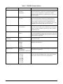
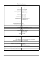
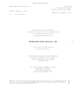
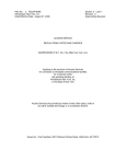
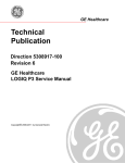
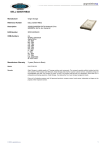
Section 61180403L1-5B
Issue 2, December 2004
CLEI Code: VAIMZ70J_ _
®
Total Access® 1500 FXS/DPO Access Module
Installation and Maintenance Practice
CONTENTS
1. General .................................................................... 1
2. Installation............................................................... 2
3. Provisioning ............................................................ 3
4. Test Features ......................................................... 11
5. Maintenance .......................................................... 11
6. Specifications ........................................................ 11
7. Warranty and Customer Service ........................... 11
FXS/DPO
1180403L1
STATUS
REM
FIGURES
Figure 1. FXS/DPO ..................................................... 1
Figure 2. DIP Switches Detail..................................... 6
Figure 3. FXS/DPO Menu Tree ................................ 10
AP
TABLES
Table 1. Compliance Codes ........................................ 2
Table 2. Front Panel LEDs and Switch ....................... 3
Table 3. Time Slot and Wiring Interconnect............... 4
Table 4. DIP Switches................................................. 5
Table 5. FXS/DPO General Options ........................... 7
Table 6. FXS/DPO Mode Options .............................. 8
Table 7. FXS/DPO Tandem Options........................... 9
Table 8. Specifications .............................................. 12
1. GENERAL
This practice is an installation and maintenance guide
for the ADTRAN® Total Access® 1500 Foreign
Exchange Station/Dial Pulse Originate (FXS/DPO)
access module. Figure 1 illustrates the FXS/DPO
(P/N 1180403L1) front panel.
Revision History
This is the second revision of this practice. This release
of the document includes the addition of the NBOC
option and the TO w/SC operating mode precipitated by
Line Interface Unit (LIU) software updates to R36 or
later. Time slot and wiring interconnect information for
the 19-inch and 23-inch Total Access 1500 chassis and
hardware and software provisioning information has
been included. This revision reflects a general
document update and change to the Warranty information.
61180403L1-5B
Figure 1. FXS/DPO
Description
The FXS/DPO is designed specifically for the Total
Access 1500 chassis and is not used in any other
product. The FXS/DPO provides for a 2-wire analog
interface between a Voice Frequency (VF) transmission
and signaling facility and the Total Access 1500 Pulse
Code Modulation (PCM) backplane. The FXS interface
provides for simultaneous signaling in each direction
for use with 2-wire Off-Premises Station Lines, carrier
extended PBX Trunks, or subscriber line Foreign
Exchanges using ground or loop start signaling systems.
The unit is multifunctional and can be hardware or
software provisioned to operate in any one of the
following modes:
•
•
•
•
•
•
Loop Start
Ground Start
TR08 Single Party (SP)
TR08 Universal Voice Grade (UVG)
TR08 Auto
Private Line Automatic Ringdown (PLAR) D4
Trademarks: Any brand names and product names included in this document are
trademarks, registered trademarks, or trade names of their respective holders.
1
•
•
•
•
•
This device complies with Part 15 of the FCC rules.
Operation is subject to the following two conditions:
PLAR D3
Tandem
DPO
FX Ringdown
TO w/Sealing Code
1. This device may not cause harmful interference.
2. This device must accept any interference received,
including interference that may cause undesired
operation.
Features
The basic features of the FXS/DPO include the
following:
Changes or modifications not expressly approved by
ADTRAN could void the user’s authority to operate this
equipment.
• µ-law encoding and decoding
• Supports ground start, loop start, PLAR, DPO, and
Tandem, TR08SP, TR08UVG, TR08AUTO, and
FX Ringdown
• Supports 900 ohms (+2.16 µF) and 600 ohms
(+2.16 µF) 2-wire VF interfaces
• Receive TLP range of -9.0 dB to 0.0 dB
• Transmit TLP range of -7.0 dB to +9.0 dB
Supports CLASS®
Hot swappable
Long loop capability: 1650 ohms nominal
V.90 Modem compliant
Extended temperature range of –40ºC to +65ºC
Meets UL 60950, NEBS Level 3, PUB 43801, and
GR57
• Call Forward Disconnect
•
•
•
•
•
•
Compliance
Table 1 shows the compliance codes for the FXS/DPO.
The FXS/DPO is NRTL listed to the applicable UL
standards. The FXS/DPO is to be installed in a restricted
access location and in a Type “B” or “E” enclosure
only.
The Total Access 1500 chassis frame ground terminal
must be connected to an earth ground to ensure that the
front panel of the FXS/DPO is properly grounded via
the backplane connector.
2. INSTALLATION
C A U T I O N !
SUBJECT TO ELECTROSTATIC DAMAGE
OR DECREASE IN RELIABILITY.
HANDLING PRECAUTIONS REQUIRED.
After unpacking the FXS/DPO, inspect it for damage. If
damage has occurred, file a claim with the carrier, then
contact ADTRAN Customer Service. Refer to the
Warranty and Customer Service section for further
information. If possible, keep the original shipping
container for returning the FXS/DPO for repair or for
verification of shipping damage.
CAUTION
Electronic modules can be damaged by ESD.
When handling modules, wear an antistatic
discharge wrist strap to prevent damage to
electronic components. Place modules in
antistatic packing material when transporting
or storing. When working on modules, always
place them on an approved antistatic mat that is
electrically grounded.
Table 1. Compliance Codes
Code
2
Input
Output
Power Code (PC)
C
C
Telecommunication Code (TC)
–
X
Installation Code (IC)
A
–
Issue 2, December 2004
61180403L1-5B
Instructions for Installing the Module
To install the FXS/DPO, perform the following steps:
1. If present, remove the Access Module Blank (P/N
1175099L1) from the appropriate access module
slot of the Total Access chassis.
2. Pull the ejector latch, located on the lower lefthand side of the FXS/DPO front panel, from its
closed position.
3. Hold the FXS/DPO by the front panel while
supporting the bottom edge of the module with the
ejector latch opened to engage the chassis edge.
4. Align the module edges to fit in the lower and
upper guide grooves for the access module slot.
5. Slide the module into the access module slot.
Simultaneous thumb pressure at the top (above the
STATUS LED) and at the bottom (below the
electrostatic caution symbol) of the module will
ensure that the module is firmly positioned against
the backplane of the chassis.
6. Secure the FXS/DPO in place by pushing in on the
ejector latch.
When the FXS/DPO first powers up it performs the
power up self-tests. Once the power up self-test is
complete, the status LEDs will reflect the true state of
the hardware.
Front Panel LEDs
The FXS/DPO provides front panel LEDs to display
status information. See Table 2 for a listing of the front
panel LEDs and their indications.
Time Slot Assignment
For time slot assignments in the Dual T1 mode and in
the Quad T1 mode, see Table 3 on page 4. The Total
Access 1500 platform can have multiple time slots in
the T1 data stream assigned to each physical slot in the
channel bank. The Total Access 1500 allows craftselectable time slots using the electronic provisioning
interface. The system will automatically map DS0s in
the T1 as determined by the Line Interface Unit (LIU)
operational configuration. Manual mapping is available
via the LIU menu.
61180403L1-5B
Table 2. Front Panel LEDs and Switch
Label
Condition
BUSY
Off
Module is in an on-hook or
idle condition
Green
Module is in an off-hook or
busy condition
REM
Switch
AP
Description
Yellow
Module is in a digital or
metallic test
Red
Module failure has been
detected
Green
Module software provisioned
by Line Interface Unit (LIU)
Off
Module hardware provisioned
by Dip Switches SW1, SW2,
SW3, and SW4
Description
Recessed pushbutton toggles between
hardware provisioning and software
provisioning
Connections
Four 50-pin male amphenol connectors on the 23-inch
Total Access 1500 backplane and three on the 19-inch
chassis packplane provide the interconnect wiring for
each of the access module physical slots. The FXS/DPO
requires P1 (Pair 1 T/R) on the 23-inch chassis. In the
19-inch chassis, Slots 1-6 use P1, Slots 7-12 use P2, and
Slots 13-18 use P3. See Table 3 on page 4 for wiring
interconnect details.
3. PROVISIONING
Provisioning options are either hardware provisioned;
using DIP switches on the FXS/DPO printed circuit
board, or software provisioned; using the craft interface
(ADMIN) on the System Controller Unit (SCU).
Selection of hardware or software provisioning is determined by the front panel recessed pushbutton AP (see
Table 2).
Issue 2, December 2004
3
Table 3. Time Slot and Wiring Interconnect
Physical
Slot
Associated T1/DS0
Amphenol Connections
Dual T1
Quad T1
(D4)
Quad T1
(D1D)
1
A1
A1
A1
2
A3
A5
3
A5
4
Interconnect
Wiring
23” Chassis
1180001L1
19” Chassis
1180019L1
1
P1 - 26/1
P1 - 26/1
T/R
A9
1
P1 - 27/2
P1 - 30/5
T/R
A9
A17
1
P1 - 28/3
P1 - 34/9
T/R
A7
A13
A2
1
P1 - 29/4
P1 - 38/13
T/R
5
A9
A17
A10
1
P1 - 30/5
P1 - 42/17
T/R
6
A11
A21
A18
1
P1 - 31/6
P1 - 46/21
T/R
7
A13
B1
B1
1
P1 - 32/7
P2 - 26/1
T/R
8
A15
B5
B9
1
P1 - 33/8
P2 - 30/5
T/R
9
A17
B9
B17
1
P1 - 34/9
P2 - 34/9
T/R
10
A19
B13
B2
1
P1 - 35/10
P2 - 38/13
T/R
11
A21
B17
B10
1
P1 - 36/11
P2 - 42/17
T/R
12
A23
B21
B18
1
P1 - 37/12
P2 - 46/21
T/R
13
B1
C1
C1
1
P1 - 38/13
P3 - 26/1
T/R
14
B3
C5
C9
1
P1 - 39/14
P3 - 30/5
T/R
15
B5
C9
C17
1
P1 - 40/15
P3 - 34/9
T/R
16
B7
C13
C2
1
P1 - 41/16
P3 - 38/13
T/R
17
B9
C17
C10
1
P1 - 42/17
P3 - 42/17
T/R
18
B11
C21
C18
1
P1 - 43/18
P3 - 46/21
T/R
19
B13
D1
D1
1
P1 - 44/19
N/A
T/R
20
B15
D5
D9
1
P1 - 45/20
N/A
T/R
21
B17
D9
D17
1
P1 - 46/21
N/A
T/R
22
B19
D13
D2
1
P1 - 47/22
N/A
T/R
23
B21
D17
D10
1
P1 - 48/23
N/A
T/R
24
B23
D21
D18
1
P1 - 49/24
N/A
T/R
Hardware Provisioning
DIP switches SW1, SW2, SW3, and SW4 are used to
provision many of the FXS/DPO options. Table 4 on
page 5 summarizes the options provisioned by the DIP
switches. Figure 2 on page 6 provides a graphic detail
of the four switches and the printed circuit board
markings.
4
Port
NOTE
Manual switches can only be used for the
negative portion of the TLP range. For
example, a switch setting of TX32 corresponds
to –3.2 dB.
Issue 2, December 2004
61180403L1-5B
Table 4. DIP Switches
Sw.-Segment
Label
Function/Description
1-1
D3/D4
D3 or D4 Signaling (PLAR only)
1-2
1-3
MODE 1/OFF
MODE 2/OFF
1-4
GS/LS
1-5
AUTO_TERM/OFF
1-6
900/600
SW1-2
SW1-3
Mode Selected
OFF
OFF
FXS
OFF
MODE 2
DPO
MODE 1
OFF
Tandem
MODE 1
MODE 2
PLAR
Ground Start or Loop Start
Reserved for future use
Selects the Impedance of the 2-wire interface:
900 + 2.16 µF or 600 + 2.16 µF
1-7
RTG/OFF
Ringback Tone Generation (tandem and PLAR modes only)
1-8
DTG/OFF
Dialtone Generation (tandem and PLAR modes only)
2-1
DPC/OFF
Reserved for future use
2-2
2-3
2-4
2-5
2-6
2-7
2-8
RX64/OFF
RX32/OFF
RX16/OFF
RX08/OFF
RX04/OFF
RX02/OFF
RX01/OFF
Receive attenuation in 0.1 dB increments (values are additive up to a total
of 9.0 dB)
3-1
SD/OFF
Example:
RX32 = 3.2 dB
RX01 = 0.1 dB
3.3 dB Total receive attenuation
Selects signaling on the loop during a Carrier Fail Alarm (CFA)
SD = Busy during CFA
OFF = Idle during CFA
Transmit attenuation in 0.1 dB increments (values are additive up to a
total of 7.0 dB)
3-2
3-3
3-4
3-5
3-6
3-7
3-8
TX64/OFF
TX32/OFF
TX16/OFF
TX08/OFF
TX04/OFF
TX02/OFF
TX01/OFF
4-1
IMM/WINK
Tandem start mode: Immediate or Wink Start
4-2
REV/NORM
Tandem battery mode: Reverse or Normal battery
4-3
4-4
4-5
4-6
4-7
4-8
NB64/OFF
NB32/OFF
NB16/OFF
NB08/OFF
NB04/OFF
NB02/OFF
61180403L1-5B
Example:
TX32 = 3.2 dB
TX01 = 0.1 dB
3.3 dB Total transmit attenuation
Network Build Out Capacitance (NBOC) in 2 µF increments (values are
additive)
Issue 2, December 2004
5
SW1
ON
C & K
OFF
OFF
8
SD08
OFF
7
8
SD08
6
NB02
OFF
5
NB04
OFF
OFF
4
OFF
NORM
3
NB08
WINK
2
NB16
OFF
C & K
OFF
1
ON
NB32
7
SD08
8
NB64
OFF
6
TX01
OFF
5
TX02
OFF
REV
4
OFF
OFF
3
TX04
IMM
2
TX08
OFF
C & K
OFF
SW4
OFF
1
ON
TX16
7
SD08
8
TX32
OFF
6
RX01
OFF
5
RX02
OFF
TX64
4
OFF
OFF
3
RX04
SD
2
RX08
600
C & K
OFF
SW3
OFF
1
ON
RX16
7
DTG
RX32
LS
6
RTG
OFF
5
900
RX64
4
AUTO_TERM
DPC
OFF
3
GS
D4
2
MODE 2
1
D3
MODE 1
SW2
OFF
Switches SW1 through SW4 are used to select/deselect a particular “State” vice the labeled switch nomenclature of on/off.
Figure 2. DIP Switches Detail
Software Provisioning
The FXS/DPO is provisioned by connecting a VT100
terminal or a computer running a terminal emulation
program to the craft interface ADMIN port located on the
System Controller Unit (SCU) front panel. Connection
to the port is made via a RS-232, DB-9 cable with a
male connector.
Craft port settings are as follows:
• 9600 Baud
• No parity
• 8 Data bits
• 1 Stop bit
• No Flow Control
The provisioning options for the FXS/DPO access
module are described in the following tables:
• Table 5, FXS/DPO General Options on page 7
• Table 6, FXS/DPO Mode Options on page 8
• Table 7, FXS/DPO Tandem Options on page 9
6
Password and User ID
Password protection is a function of the SCU and is
factory disabled. If password authentication is enabled,
then the SCU will display the Logon screen. A valid
User Name and Password are required to access the
menus.
The default User Name is “user”, and the default
Password is “password”. The User Name and Password
are not case sensitive.
Menu Navigation
To traverse through the menus, select the desired entry,
and press ENTER. To work backward in the menu, press
the ESC (escape) key.
The menu tree in Figure 3 on page 10 illustrates the
path to every provisioning, performance, and test access
point in the Total Access 1500 FXS/DPO menu
Issue 2, December 2004
61180403L1-5B
.
Table 5. FXS/DPO General Options
Function
Option
Description
Mode
Loop Start
Ground Start
TR08 Single Party (3)
TR08 Universal VG (3)
TR08 Auto (3)
PLAR D4
PLAR D3
Tandem (3)
DPO
FX Ringdown (3)
TO w/SC (3)
This option selects the signaling mode of the FXS/DPO.
See Table 6 for detailed descriptions of Mode Options.
2-Wire Termination
600 ohms + 2.16 µF
900 ohms + 2.16 µF
This option selects the impedance of the 2-wire
interface.
Transmit TLP
–7.0 to +9.0 dB (+0.0)
This is the transmit channel attenuation in 0.1 dB steps.
Receive TLP
–9.0 to +0.0 dB (+0.0)
This is the receive channel attenuation in 0.1 dB steps.
Trunk Processing
Busy in CFA
Idle in CFA
This option selects signaling on the loop during a
Carrier Fail Alarm (CFA).
On-Hook Messaging
Disabled
Enabled
When On-Hook Messaging is Disabled, full battery
voltage is provided to the loop when on-hook. This is
utilized to provide compatibility with some station sets.
Note that except for Caller ID, this prevents
transmission in the on-hook state. When Enabled, a
small amount of overhead voltage is reserved for AC
transmission.
NBOC
0 - 126 µF (0 µF)
This option selects setting for Network Build Out
Capacitance to balance the FXS/DPO access module to
the loop. Setting should be equivalent to the additional
capacitance added due to the length of the cable.
Tandem Mode Options (1)
Conversion Mode
Supervision
Tandem Battery
Dial Tone Generation
Ringback Tone Generation
Forward Disconnect
DNIS Protocol
DNIS Delay (4)
See Table 7 for a detailed description of Tandem
options.
Ringback Tone Generation (2)
Disabled
Enabled
This option is used in PLAR D3, PLAR D4, or FX
Ringdown modes only. When Enabled, the FXS/DPO
provides ringback tone toward the Network.
Defaults are in bold type.
(1) Only available if Tandem Mode is selected.
(2)
Only available if PLAR D3, PLAR D4, or FX Ringdown Mode is selected.
(3)
Only provisionable through software provisioning (reference Software Provisioning on page 6).
(4) Only
available if DNIS Protocol is set to DNIS Enabled or DNIS Enabled-No Answer.
61180403L1-5B
Issue 2, December 2004
7
Table 6. FXS/DPO Mode Options
8
Mode
Description
Loop Start
This option selects ANSI T1.403 FXS Loop Start mode of operation.
Ground Start
This option selects ANSI T1.403 FXS Ground Start mode of operation.
TR08 Single Party
This option selects GR-08-Core Loop Start mode of operation.
TR08 Universal VG
This option selects GR-08-Core Ground Start mode of operation.
TR08 Auto
This option selects automatic detection of TR08 Single Party or TR08 Universal VG, based
on incoming signalling.
PLAR D4
This option selects Private Line Automatic Ringdown where onhook = 00. Signaling must
match the PLAR unit at the distant end.
PLAR D3
This option selects Private Line Automatic Ringdown where onhook = 11. Signaling must
match the PLAR unit at the distant end.
Tandem
This option selects A/B signaling on the Network side for use with a Class 4 Tandem switch.
DPO
This option selects Dial Pulse Originate for Direct-Outward Dial applications.
FX Ringdown
This is the PLAR mode of operation that allows for a FXS Loop Start unit on the distant end.
TO w/SC
This option disables signaling for Transmission Only with Sealing Current enabled. Used in 2
w/TO applications where the Network Customer Termination Equipment (NCTE) or
Customer premise equipment provide for termination of the sealing current (sealing current
sink).
Issue 2, December 2004
61180403L1-5B
Table 7. FXS/DPO Tandem Options
Function
Option
Description
Conversion Mode
Tandem Inactive
Loop Start
Ground Start
This option sets the conversion from E&M (2-state) signaling
on the PCM interface to loop start or ground start signaling on
the loop. This option MUST be configured for channel
operation, as the default value (Tandem Inactive) will not run
the state machine.
Supervision
Immediate Start
Wink Start
This option configures the E7M trunk as immediate or wink
start for both the RX and TX direction. With wink start, a
wink is sent back to the network from the FXS/DPO card
before ringing to signal line seizure for inbound calls. For
outgoing calls, a wink must be received from the switch to the
FXS/DPO card to indicate trunk seizure for the call.
Tandem Battery
Normal Battery
Reverse Battery
This option configures answer supervision for the associated
voice port. Answer supervision is indicated by reverse battery
polarity when Reverse Battery option is set. This is valid for
outbound calls only.
Dial Tone Generation
Disabled
Enabled
This option is used to generate a 5-second dial tone from the
associated FXS/DPO port when off-hook is detected. The dial
tone provided by the FXS/DPO times out after 5 seconds and
is not broken by digit input.
RingBack Tone
Generation
Disabled
Enabled
When this option is enabled, a ringback tone is provided
toward the Network.
Forward Disconnect
250 msec
500 msec
750 msec
1 second
2 seconds
This option configures the amount of time battery is removed
during far-end disconnect.
DNIS Protocol
Disabled
DNIS Enabled
DNIS Enabled - No Answer
This option selects or deselects DNIS support for appropriate
voice/data port applications.
DNIS Delay*
0.5 seconds
1.0 second
1.5 seconds
2.0 seconds
2.5 seconds
3.0 seconds
3.5 seconds
4.0 seconds
When DNIS is activated, this option defines the delay time
between the transmitted DNIS wink, which signals off-hook/
loop closure, and the off-hook sent in signaling bits.
* Only available if DNIS Protocol is set to Enabled or Enabled-No Answer.
61180403L1-5B
Issue 2, December 2004
9
1. Configuration
Unit Name
1. Loop Start
CLEI Code
Part Number
Software Revision
2. Ground Start
3. TR08 Single Party
1. Mode
7. PLAR D3
8. Tandem
4. TR08 Universal VG
5. TR08 Auto
6. PLAR D4
2. Provisioning
9. DPO
1. 600 + 2.16
2. 2-Wire Termination
10. FX Ringdown
2. 900 + 2.16
3. Transmit TLP
Enter Value (-7.0...+9.0)
4. Receive TLP
Enter Value (-9.0...+0.0)
Figure 3. FXS/DPO Menu Tree
5. Trunk Processing
1. Conversion Mode
7. NBOC
3. Tandem Battery
2. Enabled
Enter Value (0...126)
4. Dial Tone Generation
5. Ringback Tone Generation
8. Tandem(1)
1. Immediate Start
2. Wink Start
3. 750 msec
1. Normal Battery
4. 1 second
2. Reverse Battery
5. 2 seconds
1. Disabled
2. Enabled
1. 0.5 seconds
1. Disabled
2. 1.0 seconds
2. Enabled
3. 1.5 seconds
6. Forward Disconnect
8. Ringback Tone Generation(2)
1. Disabled
2. Enabled
1. 250 msec
2. 500 msec
2. Supervision
1. Disabled
11. TO w/SC
2. Loop Start
3. Ground Start
1. Busy in CFA
2. Idle in CFA
6. On-Hook Messaging
1. Tandem Inactive
7. DNIS Protocol
4. 2.0 seconds
1. Disabled
5. 2.5 seconds
2. DNIS Enabled
6. 3.0 seconds
3. DNIS Enabled - No Answer
8. DNIS Delay(3)
7. 3.5 seconds
8. 4.0 seconds
1. Circuit
3. Status
2. Mode
3. 2-Wire Termination
1. Inactive
1. Digital Network Loopback
2. Active
4. Test
2. 1004 Hz Tone Test
3. Network Hook Test
1. No Test
4. Customer Ringing Test
5. Receive TLP
6. Trunk Processing
7. On-Hook Messaging
4. To Loop and Network
1. No Test
2. Ringing
(1) Only appears if Tandem Mode is selected.
(2) Only appears if PLAR D3, PLAR D4, or FX Ringdown Mode is selected.
(3) Only appears if DNIS Protocol is enabled.
1. No Test
2. To Network
3. To Loop
2. On-Hook
3. Off-Hook
4. Transmit TLP
8. NBOC
9. Signal Bits Tx/Rx
10. Digital Test
4. TEST FEATURES
The FXS/DPO supports the following tests for each
port:
5. MAINTENANCE
The Total Access FXS/DPO does not require routine
maintenance for normal operation.
• Digital Network Loopback
• 1004 Hz Tone Generation
• Network Hook Test
• Customer Ringing Test
These test are used to support circuit turn-up and
maintenance efforts. Test functions can be activated
locally via the ADMIN port on the SCU, or remotely via
Telnet or SNMP and are initiated on an individual port
basis. The test are described below.
ADTRAN does not recommend that repairs be
attempted in the field. Repair services may be obtained
by returning the defective unit to ADTRAN. Refer to
the Warranty and Customer Service section for further
information.
Digital Network Loopback Test
The Digital Network Loopback test activates a
loopback path that takes the DS0 data received from the
network and transmits it back to the network in the
appropriate transmit time slot.
1004 Hz Tone Generation Test
The 1004 Hz Tone Generation Test generates a 1004 Hz
Digital Reference Signal (DRS) tone toward the T1
network (0 dBm fixed), toward the customer loop (RX
TLP setting), or both directions simultaneously. While
sending the DRS tone toward the customer loop the
transmit audio path (towards the T1 network) will be
interrupted.
Network Hook Test
The Network Hook Test forces the AB signaling states
towards the T1 network. The bits are set based upon the
operating mode of the channel unit.
Customer Ringing Test
The Customer Ringing Test will activate the ports ring
relay in a 2-second on and 4-second off cadence,
providing ringing toward the customer’s loop.
NOTE
The tests cannot run simultaneously. If a test is
in progress and another test is initiated, the first
test will be terminated when the new test starts.
61180403L1-5B
6. SPECIFICATIONS
Specifications for the Total Access FXS/DPO are
detailed in Table 8 on page 12.
7. WARRANTY AND CUSTOMER SERVICE
ADTRAN will replace or repair this product within the
warranty period if it does not meet its published specifications or fails while in service. Warranty information
can be found at www.adtran.com/warranty.
Refer to the following subsections for sales, support,
Customer and Product Service (CAPS) requests, or
further information.
ADTRAN Sales
Pricing/Availability:
800-827-0807
ADTRAN Technical Support
Pre-Sales Applications/Post-Sales Technical
Assistance:
800-726-8663
Standard hours: Monday - Friday, 7 a.m. - 7 p.m. CST
Emergency hours: 7 days/week, 24 hours/day
ADTRAN Repair/CAPS
Return for Repair/Upgrade:
(256) 963-8722
Repair and Return Address
Contact CAPS prior to returning equipment to
ADTRAN.
ADTRAN, Inc.
CAPS Department
901 Explorer Boulevard
Huntsville, Alabama 35806-2807
Issue 2, December 2004
11
Table 8. Specifications
Performance
Loop Current:
23 mAmp nominal
20 mAmp minimum
Transmit TLP:
–7.0 to +9.0 dBm
Receive TLP:
–9.0 to 0.0 dBm
Terminating Impedance:
900 ohms +2.16 µF
600 ohms +2.16 µF
Return Loss:
ERL ≥ 28 dB
SRL ≥ 20 dB
TransHybrid Loss:
ERL ≥ 34 dB
SRL ≥ 20 dB
Longitudinal Balance:
≥ 58 dB @ 200 to 1000 Hz
≥ 53 dB @ 3000 Hz
Frequency Response:
±0.25 dB @ 300-3000 Hz
Idle Channel Noise:
PCM Encoding/Decoding:
DC Supervisory Range:
≤ 20 dBrnCO
µ-law
1250 ohms
Power
Current Draw:
0.034 amps maximum @ –48 VDC
Physical
Dimensions:
Weight:
Height: 3.125 inches
Width: 0.62 inches
Depth: 10.1 inches
< 0.5 pound
Environment
Operating Temperature:
–40°C to 65°C
Storage Temperature:
–40°C to 85°C
Relative Humidity:
Maximum Heat Dissipation:
95 percent maximum @ 50°C, noncondensing
1.389 watts maximum
Compliance
Regulatory Agency Requirements:
UL 60950
NEBS Level 3
FCC 47CFR Part 15, Class A
Part Number
Total Access 1500 Foreign Exchange Station/Dial
Pulse Originate Access Module:
12
1180403L1
Issue 2, December 2004
61180403L1-5B