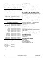
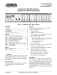
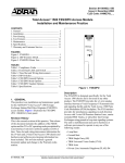
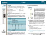
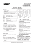
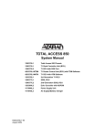
1
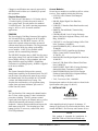
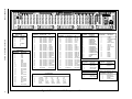
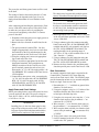
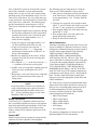
Section 61180001L1-5B
Issue 2, March 2001
CLEI Code #VAMMKJOE_ _
Total AccessTM 1500 Chassis
Installation and Maintenance
T
I
M
I
N
G
C
R
A
F
T
MJR
HST
MNR
MLT
BSY
A
R
A
C
D
C
P
RED
P
R
D
RCV
YEL
RCV
REM
TEST
REM
TEST
MASTER
STATUS
MASTER
STATUS
STATUS
STATUS
STATUS
STATUS
STATUS
STATUS
STATUS
STATUS
STATUS
STATUS
STATUS
STATUS
STATUS
STATUS
STATUS
STATUS
STATUS
STATUS
STATUS
STATUS
REM
REM
REM
REM
REM
REM
REM
REM
REM
REM
REM
REM
REM
REM
REM
REM
REM
REM
REM
REM
REM
REM
AP
AP
AP
AP
AP
AP
AP
AP
AP
AP
AP
AP
AP
AP
AP
AP
AP
AP
AP
AP
AP
AP
AP
TX
RX
MONITOR
STATUS
REM
STATUS
TX
RMT
ACO
STATUS
RED
YEL
RX
MONITOR
Figure 1. Total Access 1500 Chassis
CONTENTS
1. GENERAL .................................................................... 1
2. INSTALLATION .......................................................... 2
3. MAINTENANCE ....................................................... 12
4. WARRANTY AND CUSTOMER SERVICE ........... 12
FIGURES
Figure 1. Total Access 1500 Chassis .................................. 1
Figure 2. Power and Ground Connectors ........................... 4
Figure 3. Total Access 1500 Backplane and Pin-outs ........ 5
Figure 4. Composite Clock Wiring ..................................... 8
Figure 5. Alarm Contacts .................................................... 9
Figure 6. RS-485 Wiring ................................................... 11
TABLES
Table 1. Compliance Codes ................................................ 3
Table 2. Total Access 1500 Specifications ....................... 12
1. GENERAL
This practice provides installation and maintenance
procedures for the ADTRAN Total Access 1500
(Total Access 1500) Chassis. Figure 1 is an
illustration of the Total Access 1500 Chassis. Part
number for equipment and documents referenced in
this practice are located in the Specifications Table.
Referenced practices should be on-hand during system
installation.
Revision History
This is the second release of this document. Alarm
information for quad T1 mode has been added, and
information regarding connection to Pair Gain Test
Controller (PGTC) has been added.
Features
The Total Access 1500 Chassis, part number
1180001L1, features include the following:
61180001L1-5B
• Rackmount design
• Scalable Network Connectivity
-1-4 T1 capacity
• Protect T1 for TR-08 applications
• Three common units:
-Power Supply/Ring Generator (PSU/RGU)
-System Controller Unit (SCU)
-Line Interface Unit (LIU)
• T1 Network Interface
• 24 slots for combination of voice and data
services
• Variety of access module units
• Network management capabilities - TL1, SNMP
• Multiple configuration arrangements
• TR-08 Compatible (Modes 1 and 3)
• Supports Mechanized Loop Testing (MLT)
• FCC and UL 1950 compliant
• Meet NEBS Level 3 requirements
General Description
The Total Access 1500 Chassis is designed to meet a
variety of operating configurations and services, such
as POTS, Special Services, and xDSL. The Total
Access 1500 is intended for use in central office and
remote terminal applications. The Total Access 1500
System is comprised of the chassis, common cards,
and access modules.
This device complies with Part 15 of the FCC rules.
Operation is subject to the following two conditions:
(1) This device may not cause harmful interference,
and (2) this device must accept any interference
received, including interference that may cause
undesired operation.
Trademarks: Any brand
names 61180001L1-5
and product namesIssue
included
Section
2 in this document are
trademarks, registered trademarks, or trade names of their respective holders.
1
Changes or modifications not expressly approved by
ADTRAN could void the user’s authority to operate
this equipment.
Physical Description
The Total Access 1500 chassis is 21.2 inches wide by
3.5 inches high by 12 inches deep and is made of
heavy gauge metal. The unit mounts in a standard
23-inch wide rack. The shelf’s operating temperature
range is -40ºC to +65ºC for remote terminal
applications.
PSU/RGU
The Power Supply Unit/Ring Generator Unit supplies
-48 Vdc and 20 Hz ring voltage to the SCU and the
access modules. The PSU/RGU converts -48 Vdc
input to the required voltages needed to operate all
common units and access modules. The ring generator
circuit provides 20 Hz ring voltage to the analog
access modules. A PSU is also available which
operates with an external Ring Generator.
The PSU/RGU faceplate shows a GMT fuse for power
and ringing voltage, Fail, and 20 Hz Status LEDs. The
Power Supply circuitry is fully redundant, with each
Ring Generator supplying 20 REN. If both Ring
Generators are operating properly, 40 REN is supplied
to the access modules.
SCU
The System Controller Unit provides network
management capability for the channel bank. The SCU
can provision, test, and provide status for any card in
the channel bank. It is also available in COT and RT
versions with Mechanized Loop Testing. The
faceplate has craft interface, test equipment timing
output, alarm and status indicators, plus an ACO
(Alarm Cut-Off) switch.
LIU
The Line Interface Unit connects the channel bank to
four T1 lines, with a separate T1 that is included for
protection switching. The LIU generates control
signals and clocks used by the channel units, as well as
controls both manually and remotely initiated T1
loopbacks. It detects alarm conditions and reports the
alarm status to the SCU. The faceplate has a dual
bantam jack for T1 test access, status LEDs, and a
STATUS pushbutton.
Access Modules
Several access modules are available to deliver various
services. These modules include the following:
• OCU DP, Office Channel Unit Dataport,
1180005L1.
• DS0 DP, Digital Signal Zero Data Port,
1180003L1.
• U-BR1TE, U-Interface Basic Rate Interface card,
1180020L1.
• E&M/TO, Ear and Mouth, Transmit Only,
1180402L1.
• FXS/DPO/PLAR, 2-wire Foreign Exchange
Station/ Dial Pulse Originate/ Primary Line Auto
Ring, 1180403L1.
• FXO/DPT, 2-wire Foreign Exchange Office/ Dial
Pulse Terminate, 1180404L1.
• Quad FXS/RPOTS (RT), 2-Wire POTS (RT),
1180408L1.
• Quad FXO CPOTS, Quad Foreign Exchange
Office, Central Office Terminal POTS,
1175407L1, L2.
• Dual DS0 DP, Dual Digital Signal Zero Data Port,
1180203L2.
• Dual OCU DP, Dual Office Channel Unit Data
Port, 1180205L2.
• Dual FXO/DPT, Dual 2-Wire Foreign Exchange
Station/Dial Pulse Terminate, 1180207L2.
• Dual FXS/DPO/PLAR, Dual 2-Wire Foregin
Exchange Station/Dial Pulse Originate/Primary
Line Auto Ring, 1180208L2.
• TAU, Test Access Unit, 1180006L1.
Document part numbers for these units are found in the
Specifications table, (page 12, table 2).
2. INSTALLATION
C A U T I O N !
SUBJECT TO ELECTROSTATIC DAMAGE
OR DECREASE IN RELIABILITY.
HANDLING PRECAUTIONS REQUIRED.
After unpacking the unit, inspect it for damage. If
damage is discovered, file a claim with the carrier, then
contact ADTRAN. See Warranty and Customer Service.
NOTE
This product is intended for installation in
RESTRICTED ACCESS LOCATIONS only.
2
Section 61180001L1-5, Issue 2
61180001L1-5B
NOTE
To prevent ESD events when handling this
equipment, all personnel should utilize ESD shoes
or wrist straps, or an ESD flooring must be
present.
Compliance Codes
This product is intended to be installed in products
providing a Type “B” or “E” enclosure, and in a
Restricted Access Location. See Table 1.
Table 1. Compliance Codes
Code
Power Code (PC)
Telecommunication Code (TC)
Installation Code (IC)
Input
Output
F
X
B
C
X
–
Tools Required
The required tools for the Total Access 1500
installation are:
• Wire-wrap tool
• #2 Phillips-head screwdriver
• #1 Phillips-head screwdriver
• Straight-slot-head screwdriver
• Multimeter
• Crimping tool for power lugs
• Wire strippers
• Side cutters
• 3/16-inch wrench
Material that should be on hand:
• Four screws for mounting each Total Access 1500
shelf to the rack
• Shielded 2-wire, twisted pair cross-connect wire
with drain, such as AT&T P7 wire
• Insulated wire for power connections, in colors
dictated by your CO for battery to the Total
Access 1500 shelf and return
• Insulated wire for frame ground
• Lugs for the power wire and Frame Ground
connection
WARNING
To prevent electrical shock, do not install
equipment in a wet location or during a lightning
storm.
61180001L1-5B
CAUTION
Electronic modules can be damaged by static
electrical discharge. Before handling modules,
wear an antistatic discharge wrist strap to prevent
damage to electronic components. Place modules
in antistatic packing material when transporting
or storing. When working on modules, always
place them on an approved antistatic mat that is
electrically grounded.
Unpack and Inspect the Shelf
Each Total Access 1500 shelf is shipped in its own
cardboard shipping carton unless it was ordered as a
fully racked system. Open each carton carefully and
avoid deep penetration into the carton with sharp
objects.
After unpacking the unit, inspect it for damage. If the
equipment has been damaged, file a claim with the
carrier and then contact ADTRAN. See Warranty and
Customer Service section.
Mounting the Shelf
Mounting Bracket Orientation
The Total Access 1500 shelf comes with mounting
brackets that can be mounted with the flanges facing
forward or backward in two different locations on the
shelf sides. Therefore, the rack can be flush-mounted
or mid-mounted. Attaching the mounting brackets to
the shelf requires four screws on each side, and are
supplied with the unit.
The following are the recommended ways to mount the
shelf:
1. Flush-mounting: For flush-mounting on the rack,
use a #2 Phillips-head screwdriver and attach the
mounting brackets with the flanges facing
rearward on the rear mounting holes.
2. Mid-mounting: For mid-mounting, use a #2
Phillips-head screwdriver and attach the mounting
brackets with the flanges facing forward on the
front mounting holes.
Installing the Shelf
After attaching the mounting brackets to the Total
Access 1500 shelf sides, use the appropriate screws for
your Central Office rack type and mount the shelf in
the rack as follows:
Section 61180001L1-5 Issue 2
3
1. Flush-mount: For flush-mount systems, the Total
Access 1500 shelf must be mounted from the rear
of the rack, with mounting bracket flanges facing
rearward.
2. Mid-mount: For mid-mount systems, the Total
Access 1500 shelf must be mounted from the
front of the rack, with the mounting bracket
flanges facing forward.
NOTE
Other orientations will require either mounting
from the front or rear, and depend on the rack
type installed in the CO and the standard operating
procedures established by your CO.
Once the orientation of the shelf has been determined,
use the four appropriate screws for your CO rack and
an appropriate screwdriver and secure the Total
Access 1500 shelves in place on the rack.
Power Connections
Interconnections between the common card modules
and channel units are accomplished through the
backplane PCB. All external connections to the Total
Access 1500 are through connectors and wire-wrap
headers located on the backplane.
NOTE
When connecting power and ground wiring, be
sure to follow all local, national, and company
codes.
Frame Ground Connection
The frame ground terminal, located on the upper right
corner of the backplane (see Figure 3), should be
connected using appropriately sized wire. Use a wire
gauge that is at least the same gauge as the power
wiring. To make the frame ground connection to the
Total Access 1500:
1. Using the crimping tool, connect an appropriate
lug to each end of the appropriately sized wire.
2. Connect the ground wire from Total Access 1500
Frame ground terminal to the Equipment Rack
grounding screw.
3. Tighten the ground connection securely with a
straight-slot screwdriver.
Test Frame Ground Connection
To ensure a good ground, use a multimeter to check
continuity between the frame grounding lug and the
rack grounding strap at the top of the rack. Using a
voltmeter set to its lowest resistance range, if
applicable, place one lead on the rack’s ground strap
and the other lead on the Total Access 1500 frame
ground terminal. The reading should be 1 or 2 ohms.
Greater readings should be investigated.
Power Connection
NOTE
Connect to a reliably grounded -48 Vdc source,
which is electrically isolated from the AC source.
All permanent connections to the Total Access 1500
are made on the backplane. Figure 2 shows the
location of the power and ground connections, and
Figure 3 shows the backplane and pin-outs.
NOTE
A readily accessible disconnect device, such as a
rack mount fuse and alarm panel that is suitably
approved and rated, should be incorporated in the
fixed wiring.
TB1
1
-48 SEC
Frame
Ground
-48 PRI
RTN
IN
IN
RTN
5
TB1
Pin Number
1
2
3
4
5
Description
-48V IN PRI
-48V RTN PRI
-48V IN SEC
-48V RTN SEC
Frame Ground
Power connections use a block, labeled TB1, located
on the upper right side of the backplane (see Figure 2).
The terminals are on .375 inch centers and allow for
wire gauges up to 12 AWG. There is a separate Frame
Ground/External Ring Generator terminal, labeled
TB2, located on the bottom right side of the backplane,
and can accommodate up to 14 AWG wire. The Frame
Ground terminal routes to mechanical contact points
and provides an electrical connection to the chassis
metalwork.
Figure 2. Power and Ground Connectors
4
Section 61180001L1-5, Issue 2
61180001L1-5B
P8
5
1
P7
TB
P6
5
1
21
1
21
1
21
5
21
1
1
21
21
1
1
21
1
J31
1
J33
T1 R1
P
1
T
J29
1
R
I
B Y PA S S
1
J28
R1
J27
-48 SEC
C2
10
30
10
30
10
30
10
30
10
30
10
30
10
30
10
30
10
30
10
30
10
30
10
30
10
30
30
10
10
30
10
30
10
30
10
30
10
30
10
30
30
10
10
30
10
10
10
30
10
30
30
10
10
-48 SEC
MLT
30
3 TB2
I
N
R
T
N
RN1
RN2
40
20
PAIR 1
40
20
40
20
40
20
40
20
T/R
40
20
40
20
P2
40
PAIR 2
20
40
20
40
20
40
20
40
T1 / R1
20
40
40
20
P3
20
PAIR 3
40
20
40
20
40
20
40
E / SG
20
40
20
40
40
20
P4
PAIR 4
20
40
M / SB
20
20
40
40
26
50
26
50
26
50
26
25
1
25
1
25
1
25
1
Section 61180001L1-5 Issue 2
Ethernet (J33)
Pin Number
Description
1
ETHRTX +
2
ETHRTX 3
ETHRRX +
4
X
5
X
6
ETHRRX 7
X
8
X
RS-232 (J34)
Pin Number
Description
1
Frame Ground
2
TxD
3
RxD
4
RTS
5
CTS
6
DSR
7
GND
8
DCD
9
No Connect
10
No Connect
11
No Connect
12
No Connect
13
No Connect
14
No Connect
15
TXC
16
No Connect
17
RXC
18
No Connect
19
No Connect
20
DTR
21
No Connect
22
No Connect
23
No Connect
24
EXTC
25
No Connect
Amphenol Connectors
Pin Number
P1, P2, P3, P4
1
Ring – Ch Slot 1
2
Ring – Ch Slot 2
3
Ring – Ch Slot 3
4
Ring – Ch Slot 4
5
Ring – Ch Slot 5
6
Ring – Ch Slot 6
7
Ring – Ch Slot 7
8
Ring – Ch Slot 8
9
Ring – Ch Slot 9
10
Ring – Ch Slot 10
11
Ring – Ch Slot 11
12
Ring – Ch Slot 12
13
Ring – Ch Slot 13
14
Ring – Ch Slot 14
15
Ring – Ch Slot 15
16
Ring – Ch Slot 16
17
Ring – Ch Slot 17
18
Ring – Ch Slot 18
19
Ring – Ch Slot 19
20
Ring – Ch Slot 20
21
Ring – Ch Slot 21
22
Ring – Ch Slot 22
23
Ring – Ch Slot 23
24
Ring – Ch Slot 24
25
No Connect
P5
MLT RA
MLT RB
MLT RC
MLT RD
SLV B
SLV D
OH B
OH D
PROC B
PROC D
LOCK B
LOCK D
SMAS RA
SMAS RB
SMAS RC
SMAS RD
TMAJ
No Connect
No Connect
No Connect
No Connect
SEZBY
No Connect
No Connect
No Connect
T1 Connections
Pin Number P7 – Protect P8 – T1 D P9 – T1 C
1
2
3
4
5
T Protect
R Protect
T1 Protect
R1 Protect
Frame
Ground
TD
RD
T1
R1 D
Frame
Ground
TC
RC
T1 C
R1 C
Frame
Ground
Amphenol Connectors
Pin Number
P1, P2, P3, P4
26
Tip – Ch Slot 1
27
Tip – Ch Slot 2
28
Tip – Ch Slot 3
29
Tip – Ch Slot 4
30
Tip – Ch Slot 5
31
Tip – Ch Slot 6
32
Tip – Ch Slot 7
33
Tip – Ch Slot 8
34
Tip – Ch Slot 9
35
Tip – Ch Slot 10
36
Tip – Ch Slot 11
37
Tip – Ch Slot 12
38
Tip – Ch Slot 13
39
Tip – Ch Slot 14
40
Tip – Ch Slot 15
41
Tip – Ch Slot 16
42
Tip – Ch Slot 17
43
Tip – Ch Slot 18
44
Tip – Ch Slot 19
45
Tip – Ch Slot 20
46
Tip – Ch Slot 21
47
Tip – Ch Slot 22
48
Tip – Ch Slot 23
49
Tip – Ch Slot 24
50
No Connect
P10 – T1 B
P11 -T1 A
TB
RB
T1 B
R1 B
Frame
Ground
TA
RA
T1 A
R1 A
Frame
Ground
P5
MLT TA
MLT TB
MLT TC
MLT TD
SLV A
SLV C
OH A
OH C
PROC A
PROC C
LOCK A
LOCK C
SMAS TA
SMAS TB
SMAS TC
SMAS TD
TSTALM
No Connect
No Connect
No Connect
No Connect
SEIZE
No Connect
No Connect
No Connect
24
20
24
PGTC
50
Alarm Outputs (P13)
Pin Number
Description
1
VMJ/AMJNO
2
VMJ/AMJCOM
3
VMJ/AMJNC
4
VMN/BMJNO
5
VMN/BMJCOM
6
VMN/BMJNC
7
AudMJ/CMJNO
8
AudMJ/CMJCOM
9
AudMJ/CMJNC
10
AudMN/DMJNO
11
AudMN/DMJCOM
12
AudMN/DMJNC
13
AUX/BANKMJNO
14
AUX/BANKMJCOM
15
AUX/BANKMJNC
16
-48ALM
17
GND
TB1
Pin Number Description
1
-48V IN PRI
2
-48V RTN PRI
3
-48V IN SEC
4
-48V RTN SEC
5
Frame GND
RS-485 (P12)
Pin Number
Description
1
RS 485 A
2
RS 485 B
3
Frame Ground
5
Figure 3. Total Access 1500 Backplane and Pin-outs
40
P5
20
40
20
50
26
25
1
D1
20
P1
E
D
C
B
A
40
E
D
C
B
A
20
E
D
C
B
A
40
20
20
D2
20
1
SMAS
10
10
30
21
21
R
J25
1
T
30
21
1
T1 R1
D
10
21
R
10
1
T
IN
21
1
RTN
1
5
T1 R1
C
J26
21
1
P9
R
30
21
T
IN
1
1
RTN
21
5
T1 R1
B
E
D
C
B
1
P10
R
21
21
1
T
J30
21
1
J1
1
5
T1 R1
A
21
21
R
J32
1
T
J34
MGMT
RS485
J2
21
P11
1
SW2
A
B
RS485
J3
ALM
J4
-48
AUX
J5
NO COM NC
AMN
J6
NO COM NC
AMJ
J7
NO COM NC
VMN
J8
NO COM NC
VMJ
DIS
EN
17
NO COM NC
J9
1
1
P12
1
B
AUX2
J10
21
A
J11
1
B
AUX1
J13
21
A
J14
1
B
RMT
J15
21
A
B
ACO
J17
1
A
–
J18
+
LOCCK
J19
C1
–
J20
21
1
+
CLK OUT
J21
21
–
J22
1
J23
J24
21
P13
17
+
CLK IN
J16
1
J12
P14
OUT
TERM
O
N
O
N
61180001L1-5B
SW1
IN
CLK
40
20
Composite Clock/Alarms (P14)
Pin Number
Description
1
CLKIN +
2
CLKIN 3
FRAME GROUND
4
CLKOUT +
5
CLKOUT 6
Frame Ground
7
LOCCK+
8
LOCCK9
Frame Ground
10
ACOA
11
ACOB
12
RMTA
13
RMTB
14
AUX1A
15
AUX1B
16
AUX2A
17
AUX2B
TB2
Pin Number Description
1
Frame Ground
2
20 HZ RTN
3
20 HZ EXT
Metallic Loop Test Bypass Pair (P6)
Pin Number Description
1
2
3
4
BYPASS TIP
BYPASS RING
INHIBIT
Frame Ground
The power bus and frame ground route to all the cards
in the shelf.
The number of shelves that can be placed in a 7-foot
central office rack depends on the type of service
deployed and the number of access modules in the
shelf.
After connecting and checking the ground to the Total
Access 1500 shelf, connect power to the shelf. Check
to make sure your power source is providing the
correct power and polarity to the shelf. To connect
power to the shelf:
1. Determine which fuse pairs are to supply power to
the Total Access 1500 shelf.
2. Remove the fuses from the A and B slots for the
pair.
3. The power terminal is labeled TB1. Cut four
lengths of appropriately sized wire to reach from
the terminals on the fuse and alarm panel to the
power terminals on the Total Access 1500 shelf.
4. Using the crimping tool, connect an appropriate
lug to each end of the wires.
5. Using a screwdriver appropriate for the fuse and
alarm panel terminals, and a straight slot or
Phillips screwdriver for the Total Access 1500
power terminal, connect the ends of one wire
between the “A” CO -48 Vdc supply and the “-48
Vdc PRIMARY IN” terminal on the Total Access
1500 backplane.
6. Connect three more power wires, connecting the
“A” CO -48 Vdc return with -48 Vdc PRIMARY
RTN; “B” CO -48 Vdc supply with -48 Vdc
SECONDARY IN; and “B” CO -48 Vdc RTN
with -48 Vdc SECONDARY RTN.
Apply Power and Check Voltage
Before proceeding further, ensure that power has been
correctly applied to the shelf. The proper voltage to
Total Access 1500 is -48 Vdc, with an operating range
of -42 Vdc to -56 Vdc.
WARNING
Installing fuses in the fuse alarm panel at this
stage will provide power to the shelf. There will
be power to pins on the backplane and inside the
shelf. Exercise caution to avoid electric shock.
6
NOTE
The chassis may be powered by multiple power
sources. Disconnect all sources prior to servicing.
NOTE
The branch circuit overcurrent protection shall
be a fuse or circuit breaker rated for a maximum
of -48 Vdc @ 5.0A. Include the appropriate input
current rating for the product.
1. Install appropriate fuses (5 AMP max) in the slots
in the fuse and alarm panel that services the Total
Access 1500 shelf.
2. Using a voltmeter, place the common (normally
black) lead on the TB1 -48 Vdc PRIMARY RET
terminal and the DC volts (normally red) lead on
the TB1 -48 Vdc PRIMARY IN terminal. The
reading should be in the operating range of
-42 Vdc to -56 Vdc, with a nominal value of -48
Vdc. Note the “–” polarity.
3. Using a voltmeter, test the connection using the
TB1 -48 Vdc SECONDARY RTN terminal and
the TB1 -48 Vdc SECONDARY IN terminal.
4. Remove the fuses from the fuse and alarm panel
slots that provide power to the Total Access 1500.
Data Connections
An external composite clock input is required in the
Central Office Terminal (COT) when deploying
services from Total Access 1500. The following steps
provide instruction on how to wire external composite
clock to a single Total Access 1500.
1. Determine the “+”, “–” and drain or ground wires
from the CO clock source.
2. Using wire strippers, strip 1 to 1 1/2 inches of the
insulation from the end of the clock source
twisted pair, shielded, drop wire.
3. Using the wire-wrap tool, wire-wrap the “+” wire
from the clock source to the pin marked “+” on
connector P14, “CLK IN.”
4. Wire-wrap the “–” wire from the clock source to
the pin marked “–” on connector P14, “CLK IN.”
5. Wire-wrap the drain or shield wire from the clock
source to the pin marked “ ” on connector P14,
“CLK IN.”
6. Tie the clock source wire neatly to the frame.
7. On SW1 mounted to the left of P14, move the
switch to the “IN” position.
Section 61180001L1-5, Issue 2
61180001L1-5B
Up to 14 dual LIU systems or 28 single LIU systems
may be daisy chained to a single output from the
timing source, so only one wire run is required from
the timing source for an installation of up to 14 or 28
Total Access 1500 shelves. Use wire of the same type
as was used for the wire run from the CO clock source
to the Total Access 1500 shelf. The following steps
provide instructions for connecting up to 14 or 28
Total Access 1500 shelves to a single external timing
source.
1. Determine the length of wire required to run from
the first shelf, connector P14, to the second shelf,
connector P14, which is to be wired in the same
daisy chain. Leave approximately 1 to 1 1/2
inches for wire-wrapping.
2. Using wire strippers, strip approximately 1 to 1
1/2 inches from both ends of the wire run.
3. Using a wire-wrap tool, wire-wrap the “+”, “–“
and drain wires to the “+”, “–” and ground
terminal pins of connector P14, CLK-OUT, on
the top of the backplane.
4. Run the wire from P14 on the “source” shelf to
connector P14, CLK IN, on the receiving shelf
(See Figure 4).
5. Wire-wrap the “+”, “–“ of the wire run to the “+”,
“–“ terminals of P14 on the receiving shelf.
6. At SW1 of the receiving shelf, mounted to the left
of P14, move the switch right to the “OUT”
position.
7. Repeat steps 1-6 for each Total Access 1500 shelf
that is to be interconnected on the single CO
timing source.
NOTE
In any daisy chain of Total Access 1500 shelves
using a single timing source, only the first shelf
in the chain should have the SW1 switch set to “
IN.” All the remaining shelves in the chain
should have SW1 set to “OUT.”
Wiring Test Access
A four-lead (T, R, I, and drain) common test access
bus is provided for metallic test access to all customer
loops and is labeled P6 on the backplane. If the Total
Access 1500 being installed will use these testing
features, wiring will be required to gain access to the
test leads.
The following steps are instructions for wiring the
Total Access 1500 for Metallic Loop test access.
1. After you have located the test loops and run them
to the Total Access 1500 shelf, use wire strippers
to strip approximately 1 to 1 1/2 inches from the
test leads.
2. Using the wire-wrap tool, wire-wrap the central
office “T” and “R” leads to the Total Access 1500
“R” and “T” pins, respectively, on terminal P6.
3. Wire-wrap the inhibit wire of the cable to the top
pin labeled “I” on P6.
4. Wire-wrap the drain wire of the cable to the
bottom pin labeled ground on P6.
5. Neatly tie down the test cable pair.
Alarm Connections
Alarming is dependent on how the Total Access 1500
system is configured. When the Total Access 1500 is
configured as a channel bank using a single or dual T1
feed, the alarm outputs should be represented by
VMJ(Visual Major), VMN(Visual Minor),
AMJ(Audible Major), AMN(Audible Minor),
AUX(Auxiliary) and -48. However, if the Total
Access 1500 bank is configured as a DLC using quad
T1 feed, the alarm outputs should be represented by
T1A(A Digroup Major), T1B(B Digroup Major),
T1C(C Digroup Major), T1D(D Digroup Major),
BANK(Bank System Major), and -48. In the DLC
mode, the Total Access 1500 separately monitors the
performance of each digroup (A, B, C and D) and the
bank. The DLC mode assures that an alarm at the
digroup level provides appropriate central office and
remote information.
The Total Access 1500 provides standard bank alarm
outputs. Each of the alarms listed below consists of a
three-pin wire-wrap header that connects to the SCU
for alarm management. The SCU provides the
necessary electronic circuits for a NO/COM/NC
contact arrangement. The alarms are:
• Major-Visual Output
• Minor-Visual Output
• Major-Audible Output
• Minor-Audible Output
• AUX Output
• ACO Alarm Input
The alarming configuration is selected as an LIU
option through the VT100 craft interface.
Connect MLT
Metallic Loop test access is gained by wiring into the
connector P6, on the right side of the backplane.
61180001L1-5B
Section 61180001L1-5 Issue 2
7
+
–
+
–
CO TIMING
SW1
IN
P14
OUT
1
O
N
17
CLK
+
TERM
SW1
P14
OUT
1
P13
–
CLK IN
+
–
CLK OUT
+
–
LOCCK
A
B
ACO
A
B
RMT
A
B
AUX1
A
B
AUX2
NO COM NC
NO COM NC
NO COM NC
NO COM NC
-48
VMJ
VMN
AMJ
AMN
AUX
ALM
DIS
EN
17
NO COM NC
–
+
A
–
LOCCK
1
P12
1
17
+
TERM
+
CLK OUT
P11
5
1
P10
5
1
P9
5
1
P8
5
1
B
A
ACO
P7
A
B
AUX1
A
B
AUX2
TB
P6
5
B
RMT
O
N
O
N
IN
CLK
–
CLK IN
1
SW2
A
B
RS485
5
T
RS485
R
T1 R1
A
T
R
T1 R1
B
T
R
T1 R1
C
T
R
T1 R1
D
T
R
J33
T1 R1
P
T
J29
R
I
B Y PA S S
C1
R1
MLT
C2
TOTAL ACCESS 1500 CHASSIS
T/R
P2
PAIR 2
T1 / R1
P3
PAIR 3
E / SG
P4
PAIR 4
I
N
RN1
RN2
R
T
N
M / SB
PGTC
50
26
50
26
50
26
50
26
25
1
25
1
25
1
25
1
P5
50
26
25
1
D1
PAIR 1
3 TB2
D2
P1
SMAS
SW1
IN
P14
OUT
1
O
N
17
CLK
+
TERM
SW1
P14
OUT
1
P13
–
CLK IN
+
–
CLK OUT
+
–
LOCCK
A
B
ACO
A
B
RMT
A
B
AUX1
A
B
AUX2
NO COM NC
NO COM NC
NO COM NC
NO COM NC
-48
VMJ
VMN
AMJ
AMN
AUX
ALM
DIS
EN
17
NO COM NC
–
+
A
–
LOCCK
1
P12
1
17
+
TERM
+
CLK OUT
P11
5
1
P10
5
1
P9
5
1
P8
5
1
B
A
ACO
P7
A
B
AUX1
A
B
AUX2
TB
P6
5
B
RMT
O
N
O
N
IN
CLK
–
CLK IN
1
SW2
A
B
RS485
5
T
RS485
R
T1 R1
A
T
R
T1 R1
B
T
R
T1 R1
C
T
R
T1 R1
D
T
R
J33
T1 R1
P
T
J29
R
I
B Y PA S S
C1
R1
MLT
C2
TOTAL ACCESS 1500 CHASSIS
T/R
P2
PAIR 2
T1 / R1
P3
PAIR 3
E / SG
P4
PAIR 4
I
N
RN1
RN2
R
T
N
M / SB
PGTC
P5
50
26
50
26
50
26
50
26
50
26
25
1
25
1
25
1
25
1
25
1
D1
PAIR 1
D2
P1
SMAS
3 TB2
SW1
IN
P14
OUT
1
O
N
17
CLK
+
TERM
SW1
P14
OUT
1
P13
–
CLK IN
+
–
CLK OUT
+
–
LOCCK
A
B
ACO
A
B
RMT
A
B
AUX1
A
B
AUX2
NO COM NC
NO COM NC
NO COM NC
NO COM NC
-48
VMJ
VMN
AMJ
AMN
AUX
ALM
DIS
EN
17
NO COM NC
–
+
A
–
LOCCK
1
P12
1
17
+
TERM
+
CLK OUT
P11
5
1
P10
5
1
P9
5
1
P8
5
1
B
A
ACO
P7
A
B
AUX1
A
B
AUX2
TB
P6
5
B
RMT
O
N
O
N
IN
CLK
–
CLK IN
1
SW2
A
B
RS485
5
T
RS485
R
T1 R1
A
T
R
T1 R1
B
T
R
T1 R1
C
T
R
T1 R1
D
T
R
T1 R1
P
J33
T
J29
R
I
B Y PA S S
C1
R1
MLT
C2
TOTAL ACCESS 1500 CHASSIS
T/R
P2
PAIR 2
T1 / R1
P3
PAIR 3
E / SG
P4
PAIR 4
I
N
RN1
RN2
R
T
N
M / SB
PGTC
P5
50
26
50
26
50
26
50
26
50
26
25
1
25
1
25
1
25
1
25
1
D1
PAIR 1
D2
P1
SMAS
3 TB2
Figure 4. Composite Clock Wiring
8
Section 61180001L1-5, Issue 2
61180001L1-5B
Connecting Alarm Outputs
Depending on the vendor equipment employed at the
CO, wiring external alarms from the Total Access
1500 shelf will vary slightly. The important
consideration is whether the external alarm equipment
requires a Normally Open (NO) or Normally Closed
(NC) circuit to pass an alarm. After determining what
the CO equipment requires, connection can be made to
the equipment from the Total Access 1500 shelf, see
Figure 5 for location of alarm contacts. The following
steps are instructions for connecting alarm outputs to
the Total Access 1500.
5. Connect, using wire-wrap or lugs, as appropriate,
the two wires to the appropriate terminals on the
external alarm relay device being used.
Connecting Miscellaneous Alarm Inputs
There are four external alarm inputs that can be
reported to the SCU on the Total Access 1500 shelf.
These are marked ACO, RMT, AUX and AUX2, see
Figure 5. Terminal B supplies a -48 Vdc source.
Terminal A expects -48 Vdc if an alarm condition
exists on the alarmed equipment.
The following steps should be used to connect an
external alarm input to the shelf:
P13
1
17
NO COM NC NO COM NC NO COM NC NO COM NC NO COM NC
VMJ (T1A)
VMN (T1B)
AMJ (T1C)
AMN (T1D)
-48
AUX (BANK) ALM
Alarm Outputs (P13)
Pin Number
Description
1
VMJ (T1A) NO
2
VMJ (T1A) COM
3
VMJ (T1A) NC
4
VMN (T1B) NO
5
VMN (T1B) COM
6
VMN (T1B) NC
7
AMJ (T1C) NO
8
AMJ (T1C) COM
9
AMJ (T1C) NC
10
AMN (T1D) NO
11
AMN (T1D) COM
12
AMN (T1D) NC
13
AUX (BANK) NO
14
AUX (BANK) COM
15
AUX (BANK) NC
16
-48ALM
17
GND
Figure 5. Alarm Contacts
NOTE
Each three-pin alarm header is wired the same
way for the specified alarm.
1. Determine whether the external alarm reporting
device uses a normally open or normally closed
circuit for alarm relay.
2. Using standard telco cross connect wire,
determine and cut the length required to reach
from the alarm headers to the alarm-reporting
device.
3. Using wire strippers, strip 1 to 2 inches from both
ends of the wire.
4. Using a wire-wrap gun, wire-wrap one strand to
the center pin (common) from the Total Access
alarm relay header, and the other strand to either
the “NO” (normally open) or “NC” (normally
closed) pin on the relay header.
61180001L1-5B
1. Using a #1 Phillips-head screwdriver, remove the
long, thin metal guard if it is not already off.
2. Choose an alarm header set from block, P14, on
the top of the Total Access 1500 backplane.
3. Using standard telco cross connect wire,
determine and cut the length required to reach
from the alarmed piece of equipment to the header
you chose. Allow length for 1 to 2 inches of
stripped wire for wire-wrap, and neat routing out
from the Total Access 1500 shelf.
4. Using wire strippers, strip 1 to 2 inches from both
ends of the wire.
NOTE
Omit step 5 if the alarmed piece of equipment has
its own source of -48 Vdc and does not need the
-48 Vdc feed from the Total Access 1500 shelf.
The Total Access 1500 shelf expects to see -48
Vdc on pin A of the alarm pair when an alarm
condition exists.
5. Using a wire-wrap gun, wire-wrap one wire to the
B pin of the Total Access 1500 AUX1 header
(P14), and the other end to the alarmed unit alarm
terminal marked “B.”
6. Wire-wrap one end of the second wire to the A
pin of the Total Access 1500 alarm header (P14)
and the other end to the appropriate equipment
alarm terminal.
7. Using a #1 Phillips-head screwdriver, replace the
long thin metal guard using the screws provided.
NOTE
Check with the equipment manufacturer for exact
alarm markings.
Section 61180001L1-5 Issue 2
9
Network Management Connections
The Total Access 1500 shelf integrates onto the
backplane several different management ports to allow
for remote management of the shelf. The management
interface is on the System Controller Unit (SCU)
discussed in detail in the System Description section
of the Total Access 1500 System Manual.
Up to 16 shelves can be linked together on the RS-485
bus for management of those shelves from a single
management interface.
SW2, located in the upper center of the Total Access
1500, is used to enable/disable RS-485. There is also
a 3-position wire-wrap header, P12, for the RS-485
interface.
Connecting the RS-485 Bus Between Shelves
Up to 16 shelves can be linked together for
management from a single shelf designated as host
(the other shelves will be configured as clients). This
feature allows conservation of valuable external
management ports within the CO, and provides local
or remote management for up to 16 shelves from the
craft interface on front of the host SCU, or from the
remote management port connections described in this
section. The following steps are instructions for
connecting the RS-485 bus between shelves.
1. Determine and cut the length of wire necessary to
reach from the RS-485 wire-wrap header, P12, in the
first shelf in the chain to the RS-485 wire-wrap header,
P12, in the second shelf. Remember to allow for
stripping the ends of the wire, routing the wires out to
the right side of the shelf to the frame, and tying down
in accordance with CO SOP.
2. Using the wire-wrap tool, connect the shielded,
twisted pair interconnect wire to the RS-485 wire-wrap
header, P12, on the host Total Access 1500 backplane.
(See Figure 6).
3. Run the interconnect wire to the backplane of the
first client shelf. Using the wire-wrap tool, connect
the two conductors and ground of the interconnect
wiring to the RS-485 wire-wrap header, P12, on the
backplane of the client shelf. (See Figure 6)
RS-232 SCU Comm Port
The Total Access 1500 can send and receive TL1
commands for NMA management over the X.25 packet
switched network. The Total Access 1500 SCU has a
built-in X.25 PAD, and the shelf is ready to connect to
the network. Access to the network is via an RS-232
connector, J34, located in the upper middle of the
backplane. The following steps are instructions for
connecting the X.25 to the Total Access 1500.
1. Connect the DB-25 data cable male connector to
the NTWK MGMT port, J34, on the Total Access
1500 backplane.
2. Connect the other end of the data cable to the
designated port of the X.25 switch.
NOTE
The CO X.25 network administrator must
configure the X.25 switch for the Total Access
1500 shelf, accomplishing tasks such as
assignment of an LDN number for the shelf.
Connect 10BaseT
The Total Access 1500 can provide SNMP
management capability over Ethernet. Access to the
network is via a RJ-45 10BaseT connector, J33, labeled
“Ethernet,” located on the upper right side of the
backplane.
To connect the Total Access 1500 shelf to the Ethernet
ring, simply plug the male RJ-45 modular connector
into the female RJ-45 port on the Total Access 1500
backplane. When planning your cable run to the Total
Access 1500 shelf, be sure to allow enough cable for
routing the cable to the right from the backplane
connector to the frame, and for neat tie-off in
accordance with CO SOP.
Connect to Pair Gain Test Controller (PGTC)
Use a straight through 50-pin Amp cable to connect the
Pair Gain Test controller to the PGTC interface (P5) of
the Total Access 1500. P5 accepts a female connector.
If there are more shelves to be connected, repeat steps
1 through 3 for each shelf to be added to the chain.
Each shelf after the first will be a client shelf on the
daisy chain. It is important to note that there is only
one shelf designated as host on any daisy chain of up
to 16 shelves.
10
Section 61180001L1-5, Issue 2
61180001L1-5B
HOST
P12
SW1
P14
OUT
1
P13
–
CLK IN
+
–
CLK OUT
+
–
LOCCK
A
B
ACO
A
B
RMT
A
B
AUX1
A
B
AUX2
1
P12
1
17
+
TERM
NO COM NC
NO COM NC
NO COM NC
NO COM NC
-48
VMJ
VMN
AMJ
AMN
AUX
ALM
DIS
EN
17
NO COM NC
P11
5
1
P10
5
1
P9
5
1
P8
5
1
P7
TB
P6
5
O
N
O
N
IN
CLK
1
SW2
A
B
RS485
5
T
RS485
R
T1 R1
A
T
R
T1 R1
B
T
R
T1 R1
C
T
R
T1 R1
D
T
R
J33
T1 R1
P
T
J29
R
I
B Y PA S S
C1
R1
MLT
C2
TOTAL ACCESS 1500 CHASSIS
T/R
P2
PAIR 2
T1 / R1
P3
PAIR 3
E / SG
P4
PAIR 4
I
N
RN1
RN2
R
T
N
M / SB
PGTC
50
26
50
26
50
26
50
26
25
1
25
1
25
1
25
1
P5
50
26
25
1
A
B
RS485
D1
PAIR 1
D2
P1
SMAS
3 TB2
CLIENT
P12
SW1
P14
OUT
1
P13
–
CLK IN
+
–
CLK OUT
+
–
LOCCK
A
B
ACO
A
B
RMT
A
B
AUX1
A
B
AUX2
1
P12
1
17
+
TERM
NO COM NC
NO COM NC
NO COM NC
NO COM NC
-48
VMJ
VMN
AMJ
AMN
AUX
ALM
DIS
EN
17
NO COM NC
P11
5
1
P10
5
1
P9
5
1
P8
5
1
P7
TB
P6
5
O
N
O
N
IN
CLK
1
SW2
A
B
RS485
5
T
RS485
R
T1 R1
A
T
R
T1 R1
B
T
R
T1 R1
C
T
R
T1 R1
D
T
R
J33
T1 R1
P
T
J29
R
I
B Y PA S S
C1
R1
MLT
C2
TOTAL ACCESS 1500 CHASSIS
T/R
P2
PAIR 2
T1 / R1
P3
PAIR 3
E / SG
P4
PAIR 4
I
N
RN1
RN2
R
T
N
M / SB
PGTC
50
26
50
26
50
26
50
26
25
1
25
1
25
1
25
1
P5
50
26
25
1
A
B
RS485
D1
PAIR 1
3 TB2
D2
P1
SMAS
CLIENT
P12
SW1
P14
OUT
1
P13
–
CLK IN
+
–
CLK OUT
+
–
LOCCK
A
B
ACO
A
B
RMT
A
B
AUX1
A
B
AUX2
1
P12
1
17
+
TERM
NO COM NC
NO COM NC
NO COM NC
NO COM NC
-48
VMJ
VMN
AMJ
AMN
AUX
ALM
DIS
EN
17
NO COM NC
P11
5
1
P10
5
1
P9
5
1
P8
5
1
P7
TB
P6
5
O
N
O
N
IN
CLK
1
SW2
A
B
RS485
5
T
RS485
R
T1 R1
A
T
R
T1 R1
B
T
R
T1 R1
C
T
R
T1 R1
D
T
R
T1 R1
P
J33
T
J29
R
I
B Y PA S S
C1
R1
MLT
C2
TOTAL ACCESS 1500 CHASSIS
T/R
P2
PAIR 2
T1 / R1
P3
PAIR 3
E / SG
P4
PAIR 4
I
N
RN1
RN2
R
T
N
M / SB
PGTC
50
26
50
26
50
26
50
26
25
1
25
1
25
1
25
1
P5
50
26
25
1
D1
PAIR 1
3 TB2
D2
P1
SMAS
A
B
RS485
Figure 6. RS-485 Wiring
61180001L1-5B
Section 61180001L1-5 Issue 2
11
Specifications
The specifications for the Total Access 1500 Chassis
can be found in Table 2.
Table 2. Total Access 1500 Specifications
Power Requirements
Input DC Voltage: -42 to -56 VDC
DC Voltage nominal: -48 VDC
Maximum Current: (5 Amp fused)
Environmental
Operating Temperature: -40º to +65º C
Storage Temperature: -40º to +85º C
Relative Humidity: 95% maximum, non-condensing
Physical
Dimensions: 23" W x 3 1/2" H x 12" D
Weight (fully loaded): 20 lbs
(empty): 11 lbs
TA 1500 Relevant Part Numbers
TA 1500 Chassis:
SCU:
SCU COT w/MLT:
SCU RT w/MLT:
PSU/INT RG:
PSU/EXT RG:
LIU-4+P:
FXS/DPO/PLAR:
FXO/DPT:
E&M/TO:
OCU-DP:
DSO-DP:
U-BR1TE:
Dual DS0 DP:
Dual OCU DP:
Dual FXO/DPT:
Dual FXS/DPO/PLAR:
Quad R-POTS:
Test Access Card:
Quad FXO CPOTS:
1180001L1, Practice: 61180001L1-5
1180008L1, Practice: 61180008L1-5
1180008L2, Practice: 61180008L2-5
1180008L3, Practice: 61180008L3-5
1180007L1, Practice: 61180007L1-5
1180007L2, Practice: 61180007L2-5
1180109L1, Practice: 61180109L1-5
1180403L1, Practice: 61180403L1-5
1180404L1, Practice: 61180404L1-5
1180402L1, Practice: 61180402L1-5
1180005L1, Practice: 61180005L1-5
1180003L1, Practice: 61180003L1-5
1180020L1, Practice: 61180020L1-5
1180203L2, Practice: 61180203L2-5
1180205L2, Practice: 61180205L2-5
1180207L2, Practice: 61180207L2-5
1180208L2, Practice: 61180208L2-5
1180408L1, Practice: 61180408L1-5
1180006L1, Practice: 61180006L1-5
1175407L1, Practice: 61175407L1-5
Cable Assembly Part Numbers
Cable Asy., 4x50 pin
to 100-pr, 25'
Cable Asy., 4x50 pin
to 100-pr, 50'
Cable Asy., 4x50 pin
to 100-pr, 100'
Cable Asy., 4x50 pin
to 100-pr, 200'
Cable Asy., 4x50 pin
to 100-pr, 300'
12
1180011L25
3. MAINTENANCE
The Total Access 1500 Chassis does not require
programmed maintenance for design operation.
ADTRAN does not recommend that repairs be
attempted in the field. Repair services are obtained by
returning the defective unit to ADTRAN Customer
Service.
4. WARRANTY AND CUSTOMER SERVICE
ADTRAN will replace or repair this product within 10
years from the date of shipment if it does not meet its
published specifications or fails while in service
(see: ADTRAN Carrier Networks Equipment
Warranty, Repair, and Return Policy and Procedure,
document: 60000087-10).
Contact Customer and Product Service (CAPS) prior
to returning equipment to ADTRAN.
For service, CAPS requests, or further information,
contact one of the following numbers:
ADTRAN Sales
Pricing/Availability
(800) 827-0807
ADTRAN Technical Support
Presales Applications/Postsales Technical Assistance
(800) 726-8663
Standard hours: Monday-Friday, 7 a.m. - 7 p.m. CST
Emergency hours: 7 days/week, 24 hours/day
ADTRAN Repair/CAPS
Return for Repair/Upgrade
(256) 963-8722
Repair and Return Address
ADTRAN, Inc.
CAPS Department
901 Explorer Boulevard
Huntsville, Alabama 35806-2807
1180011L50
1180011L100
1180011L200
1180011L300
Section 61180001L1-5, Issue 2
61180001L1-5B