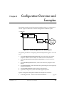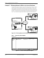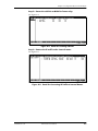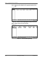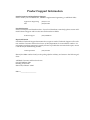
1
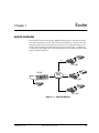
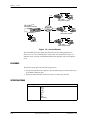
ATLAS Router
User Manual
Part Number 1200263L1-1.2A
61200263L1-1.2A
September 1998
901 Explorer Boulevard
P.O. Box 140000
Huntsville, AL 35814-4000
(256) 963-8000
© 1998 ADTRAN, Inc.
All Rights Reserved.
Printed in U.S.A.
Table of Contents
List of Figures ..................................................................................................................................................... v
Chapter 1. Router ........................................................................................................................................... 1-1
Router Overview .............................................................................................................................................. 1-1
Features ............................................................................................................................................................. 1-2
Specifications .................................................................................................................................................... 1-2
Chapter 2. Technology Overview ............................................................................................................... 2-1
IP Routing ......................................................................................................................................................... 2-1
Chapter 3. Operation ..................................................................................................................................... 3-1
Overview ........................................................................................................................................................... 3-1
Terminal Menu Structure ................................................................................................................................ 3-1
Router Menu ..................................................................................................................................................... 3-2
IP Menu ............................................................................................................................................................. 3-3
Static Routes .............................................................................................................................................. 3-3
ARP Cache ................................................................................................................................................. 3-4
Routes ......................................................................................................................................................... 3-5
Interfaces .................................................................................................................................................... 3-7
Chapter 4. Configuration Overview and Examples ................................................................................ 4-1
Example 1: IP Routing Network—ATLAS as the Central-Site Router ............................................ 4-2
Appendix A. Glossary .................................................................................................................................. A-1
Index ..........................................................................................................................................................Index-1
61200263L1-1.2A
ATLAS Router User Manual
iii
Table of Contents
iv
ATLAS Router User Manual
61200263L1-1.2A
List of Figures
Figure 1-1.
Figure 1-2.
Figure 3-1.
Figure 3-2.
Figure 3-3.
Figure 3-4.
Figure 3-5.
Figure 3-6.
Figure 3-7.
Figure 4-1.
Figure 4-2.
Figure 4-3.
Figure 4-4.
Figure 4-5.
Figure 4-6.
Figure 4-7.
External Routers ........................................................................................................................... 1-1
Internal Routers ............................................................................................................................ 1-2
Router Added to the Main Terminal Menu ............................................................................. 3-1
Router Menu Tree ........................................................................................................................ 3-2
IP Routes Menu ............................................................................................................................ 3-3
Static Routes Menu ...................................................................................................................... 3-3
ARP Cache Menu ......................................................................................................................... 3-4
Routes Menu ................................................................................................................................. 3-5
Interfaces Menu ............................................................................................................................ 3-7
ATLAS Configured for the Router Option............................................................................... 4-1
IP Routing Network with ATLAS as the Central-Site Router ............................................... 4-2
Panel for Creating Packet Endpoint .......................................................................................... 4-2
Panel for Creating Sublinks ........................................................................................................ 4-3
Panel for Connecting IP Traffic to Internal Router ................................................................. 4-3
Panel for Connecting Endpoints to Physical Interface ........................................................... 4-4
Panel for Enabling Routing......................................................................................................... 4-4
61200263L1-1.2A
ATLAS Router User Manual
v
List of Figures
vi
ATLAS Router User Manual
61200263L1-1.2A
Router
Chapter 1
ROUTER OVERVIEW
The ATLAS router uses the integral 10BaseT Ethernet port to transmit local area
network (LAN) traffic over the wide area network (WAN) to a remote LAN. By
integrating the router into the network access device, you benefit from the cost
savings of not requiring an external router. Figure 1-1 and Figure 1-2 illustrate a
conversion from an application with external routers to one using integral routers
within ADTRAN products.
Router
F-T1
TSU 100e
ATLAS
T1
Frame
Relay
Router
F-T1
TSU 100e
Router
Router
F-T1
TSU 100e
Figure 1-1. External Routers
61200263L1-1.2A
ATLAS Router User Manual
1-1
Chapter 1. Router
L
A
N
F-T1
TSU 100e
with router module
ATLAS 800PLUS
with router firmware
T1
Frame
Relay
PC
L
A
N
F-T1
TSU 100e
with router module
L
A
N
L
A
N
F-T1
PC
PC
TSU 100e
with router module
PC
Figure 1-2. Internal Routers
The Frame Relay/Router option lets the ATLAS series of Integrated Access
Devices act as a voice/data FRAD, a frame relay switch, and an IP router—in
addition to the currently available bandwidth management and switch applications.
FEATURES
The Router option provides the following features:
•
Routes IP traffic between a public or private frame relay network and the integral 10BaseT Ethernet port.
•
Routes IP traffic between virtual circuits in a frame relay network.
SPECIFICATIONS
IP Routing
Route Discovery RIP V1
RIP V2
ICMP
DHCP
ARP
IARP
UDP Relay
1-2
ATLAS Router User Manual
61200263L1-1.2A
Chapter 2
Technology Overview
IP ROUTING
Internet Protocol (IP) routing is performed at layer 3 of the Open System Interconnection (OSI) model. (Refer to the Frame Relay User Manual for a description of the
OSI model.) The routing process determines the optimal path for data packets to
travel and then moves the data packets along that path. Routers exchange information about paths or routes that reach additional LAN segments. This exchange
of routing information allows a router to build a detailed knowledge of the network topology. Criteria for selecting the best path can include such items as distance, number of hops (servers or routers), and cost of the transportation media.
ATLAS supports Routing Information Protocol (RIP), a protocol based on hops.
Each route has a set number of hops (routers or servers) that it must travel
through to reach a final destination. If a new route to a host address that has a
fewer number of hops is learned, it becomes the preferred route. When a new
route is learned, the router increments the hop count by one and immediately
broadcasts the new route over the other interfaces. To prevent routing loops, RIP
defines a hop count of 16 as an infinite or unreachable route.
61200263L1-1.2A
ATLAS Router User Manual
2-1
Chapter 2. Technology Overview
2-2
ATLAS Router User Manual
61200263L1-1.2A
Operation
Chapter 3
OVERVIEW
The Router Upgrade provides remote connectivity of LANs within an ATLAS—
from LAN-to-WAN connection or from WAN-to-WAN connection. The Router
Upgrade is included as part of the frame relay upgrade and includes an IP Router.
TERMINAL MENU STRUCTURE
The ATLAS uses hierarchical menus to access all of its features. The top-most
menu level leads to submenus which are grouped by functionality. All menu
items display in the terminal window.
Refer to the ATLAS User Manual for detailed instructions on how to navigate
through the terminal menu.
When the Router Option is enabled, the Router Menu is added to the main terminal menu (see Figure 3-1). All routing functions within ATLAS are configured
and monitored from the Router Menu.
Figure 3-1. Router Added to the Main Terminal Menu
61200263L1-1.2A
ATLAS Router User Manual
3-1
Chapter 3. Operation
ROUTER MENU
The Router Menu defines, configures, and monitors all ATLAS Router options. Figure 3-2 displays the IP Router menu tree.
IP Address
Netmask
Static Routes
Gateway
Interface
Hops
IP Address
MAC Address
ARP Cache
Time
Type
IP
Interface
TX Pending
IP Address
Netmask
Routes
Gateway
Interface
Used
Flags
Hops
TTL
Network Name
Address
Subnet Mask
Interfaces
IARP
Mode
Far-End Address
Protocol
MTU
Method
RIP
Updates
V2 Secret
Figure 3-2. Router Menu Tree
3-2
ATLAS Router User Manual
61200263L1-1.2A
Chapter 3. Operation
IP MENU
The IP Menu defines and monitors IP routes (see Figure 3-3).
Figure 3-3. IP Routes Menu
Static Routes
The Static Routes Menu manages static IP routes. You can create, modify, and
delete routes using this menu (see Figure 3-4).
Figure 3-4. Static Routes Menu
IP Address
Write Security: 3; Read Security: 5
Defines the IP address of the host or network device being routed to.
Netmask
Write Security: 3; Read Security: 5
Determines for routing the number of bits used in the above-defined IP address.
If a host address is desired for the IP address, this field must be set to
255.255.255.255.
61200263L1-1.2A
ATLAS Router User Manual
3-3
Chapter 3. Operation
Gateway
Write Security: 3; Read Security: 5
Defines the IP address of the router to receive the forwarded IP packet.
Interface
Write Security: 3; Read Security: 5
Defines the interface to which IP packets with this address will be routed. These
are either Ethernet or frame relay DLCIs.
Hops
Write Security: 3; Read Security: 5
Defines the number of router hops required to get to the network or host. Maximum distance is 15 hops.
ARP Cache
The ARP Cache Menu displays the contents of the ATLAS Address Resolution Protocol (ARP) cache (see Figure 3-5). All resolved cache entries time out after 20
minutes. Unresolved entries time out in 3 minutes.
Figure 3-5. ARP Cache Menu
IP Address
Read Security: 5
Displays the IP address used for resolving MAC address.
MAC Address
Read Security: 5
Resolves Ethernet address. If set to all zeros, there is no resolution for that
address.
Time
Read Security: 5
Displays the minutes since the entry was last referenced.
Type
Write Security: 3; Read Security: 5
Defines this entry as dynamic or static.
3-4
ATLAS Router User Manual
61200263L1-1.2A
Chapter 3. Operation
Interface
Read Security: 5
Displays the interface upon which this entry was found.
Tx Pending
Read Security: 5
Displays the number of transmit packets pending a reply.
Routes
The Routes Menu displays the contents of the ATLAS route table. All static and
discovered routes are displayed from this menu (see Figure 3-6).
Figure 3-6. Routes Menu
IP Address
Read Security: 5
Displays the IP address of the network or host destination address.
Netmask
Write Security: 3; Read Security: 5
Displays the netmask applied to the destination address.
Gateway
Read Security: 5
Displays the IP address of the host or router receiving the forwarded IP packet.
61200263L1-1.2A
ATLAS Router User Manual
3-5
Chapter 3. Operation
Interface
Read Security: 5
Displays the interface to which IP packets with this address will be routed.
Options
Local
Sent directly to the ATLAS router
EN0 IP
ATLAS Ethernet port
Endpoint Name (DLCI #)
Used
Read Security: 5
Displays the number of times the router has referenced this route.
Flags
Read Security: 5
Indicates the properties of this routing table entry, composed of the following letters:
H - route is a host route
G - route is a gateway route
D - route learned dynamically from RIP
I
- route learned from an ICMP redirect
P - route is private and is not advertised with RIP
T - route is to a triggered port (updated only when table changes)
Hops
Read Security: 5
Displays the number of router hops required to get to the network or host.
Ranges from 0 to 16. If set to 16, it is defined as infinite and cannot be routed.
TTL
Read Security: 5
Displays the number of seconds until the address is removed from table. Value of
999 means the route is static.
3-6
ATLAS Router User Manual
61200263L1-1.2A
Chapter 3. Operation
Interfaces
The Interfaces Menu (see Figure 3-7) configures and monitors all interfaces connected to the ATLAS router. These include the Ethernet and frame relay DLCIs
connected in the Packet Manager/ Packet Cncts.
Figure 3-7. Interfaces Menu
Network Name
Read Security: 5
Displays the name of the interface connected to the ATLAS router. The options are
listed below:
EN0 IP
ATLAS Ethernet port
Endpoint Name (DLCI #)
Address
Write Security: 3; Read Security: 5
Defines the individual interface IP address. If this field is left as 0.0.0.0, it is
treated as an unnumbered interface.
Subnet Mask
Write Security: 3;Read Security: 5
Defines the subnet mask applied to the address defined for this link. If the subnet
mask is unnumbered, leave as 0.0.0.0.
61200263L1-1.2A
ATLAS Router User Manual
3-7
Chapter 3. Operation
IARP (Inverse ARP)
Write Security: 3; Read Security: 5
The Inverse ARP (IARP) field is only present when this is a frame-relay network
interface. ATLAS always responds to Inverse ARP requests with its IP address for
the requested DLCI.
Enable
Atlas sends Inverse ARP packets in order to determine the IP address on
the other end of the virtual circuit. If the Inverse ARP packet is
responded to, a route is placed in the IP route table.When this field is
set to ENABLE, ATLAS dynamically sends Inverse ARP packets to determine the IP address on the other end of the virtual circuit. When an
Inverse ARP packet is not responded to, a route is placed in the IP route
table.
Disable
ATLAS responds to Inverse ARP requests with its IP address for the
requested DLCI. If set to DISABLE, ATLAS does not generate Inverse ARP
request packets. In this case, the Far-End Address parameter may be
used to statically assign a route address (see Far-End Address on page
3-8).
Far-End Address
Read Security: 3; Write Security: 5
The Far-End IP Address field is only present for frame-relay network interfaces,
and it is only selectable when Inverse ARP is disabled. The IP address of the
device on the other end of the virtual circuit may be specified. A static route to
the far-end network will be added using the interface Subnet-Mask if nonzero. If
0.0.0.0 has been specified for the Subnet-Mask, a default subnet mask is used based
on the class of the Far-End Address. (See also Subnet Mask on page 3-7.)
MTU (Maximum Transmit Unit)
Read Security: 5
Defines maximum number of bytes in a datagram transmitted over this interface.
RIP (Routing Information Protocol)
Configures RIP on this interface.
Mode
Write Security: 3; Read Security: 5
Allows RIP to be enabled or disabled on a per-interface basis.
Tx Only
RIP advertisements are periodically transmitted, but are not listened to on this virtual circuit.
Rx Only
RIP advertisements are not transmitted on this virtual circuit, but
they are listened to.
Tx and Rx
RIP advertisements are periodically transmitted and are listened to on this virtual circuit.
If mode is Off, the following menus will not be visible.
Protocol
Write Security: 3; Read Security: 5
Sets the version of RIP being used on this interface. The options are RIP V1
and RIP V2.
3-8
ATLAS Router User Manual
61200263L1-1.2A
Chapter 3. Operation
If RIP V2 is used, a user-defined secret will have to be created.
Method
Write Security: 3; Read Security: 5
Defines the method used to send RIP route advertisements. The options are
listed below:
None
Split Horizon
Poison Reverse
All routes in the router table are advertised through this
interface with no modification of the routing metric.
Only advertises routes not learned through this interface.
All routes are advertised, but the routes learned through
this interface are “poisoned” with an infinite route metric.
Updates
Write Security: 3; Read Security: 5
Defines when RIP advertisements are transmitted.
Periodic
Triggered
RIP advertisements are periodically transmitted.
RIP advertisements are transmitted only when new routes are
learned, and learned routes do not age.
V2 Secret
Write Security: 3; Read Security: 5
Defines the secret used to advertise routes when using RIP V2.
This menu item is visible only if RIP V2 is used.
61200263L1-1.2A
ATLAS Router User Manual
3-9
Chapter 3. Operation
3-10
ATLAS Router User Manual
61200263L1-1.2A
Configuration Overview and
Examples
Chapter 4
This chapter provides several step-by-step examples to help you configure your
ATLAS. Figure 4-1 illustrates an ATLAS configured for the Router option.
10.100.20.0
10BaseT
Router
IP
Pkt
Endpoint 1
T1
Port
Frame Relay
Network
Figure 4-1. ATLAS Configured for the Router Option
The general procedure for configuring the ATLAS depicted in Figure 4-1 is as follows:
1.
From Packet Manager/Packet Endpnts/Config, create the frame relay packet
endpoint. Refer to the Frame Relay User Manual for more information.
2.
From Packet Manager/Packet Endpnts/Config/Sublinks, create the necessary
PVCs.
3.
From Packet Manager/Packet Cncts, connect the frame relay endpoint to the
Router.
4.
From Dedicated Map, connect the frame relay packet endpoint to the appropriate physical interface.
5.
From Router/IP/Interfaces, enable routing on the interface.
6.
(Optional) Configure any static routes that might be required.
Specific configuration examples included in this chapter are as follows:
•
61200263L1-1.2A
IP Routing Network—ATLAS as the Central-Site Router . . . . . . . . . . . . pg. 4-2
ATLAS Router User Manual
4-1
Chapter 4. Configuration Overview and Examples
Example 1: IP Routing Network—ATLAS as the Central-Site Router
Example 1 (see Figure 4-2) depicts a typical IP routing network using an ATLAS
as the central-site router. (This ATLAS unit is the ATLAS 800PLUS with a frame
relay upgrade.) The central-site ATLAS terminates a full T1 (F-T1) frame relay
connection from the XYZ service provider, and the internal router terminates the
IP traffic. A TSU 100e with a router module is located at each of the two remote
sites. To re-create this example, follow the five-step process discussed below.
10.100.112.0
Chicago
L
A
N
F-T1
TSU 100e
with router module
Atlanta
ATLAS 800PLUS
with frame relay upgrade
T1
L
A
N
XYZ Public
Frame Relay
New York
10.100.111.0
10.100.113.0
L
A
N
F-T1
TSU 100e
with router module
Figure 4-2. IP Routing Network with ATLAS as the Central-Site Router
Step 1: Create the packet endpoint.
See Figure 4-3.
Figure 4-3. Panel for Creating Packet Endpoint
4-2
ATLAS Router User Manual
61200263L1-1.2A
Chapter 4. Configuration Overview and Examples
Step 2: Create the sublinks or DLCIs for frame relay.
See Figure 4-4.
Figure 4-4. Panel for Creating Sublinks
Step 3: Connect the IP traffic to the internal router.
See Figure 4-5.
Figure 4-5. Panel for Connecting IP Traffic to Internal Router
61200263L1-1.2A
ATLAS Router User Manual
4-3
Chapter 4. Configuration Overview and Examples
Step 4: Connect packet endpoint to the appropriate physical interface.
See Figure 4-6.
Figure 4-6. Panel for Connecting Endpoints to Physical Interface
Step 5: Enable routing on the two interfaces.
See Figure 4-7.
Figure 4-7. Panel for Enabling Routing
4-4
ATLAS Router User Manual
61200263L1-1.2A
Glossary
Appendix A
A-Law
PCM coding method as defined by the ITU-T. It is a companding standard for converting between
analog and digital in a PCM system. A-Law is mainly used in Europe. MU-Law is the North American equivalent.
ANSI T1.617-D (Annex D)
See Annex D.
Annex D
Standard for frame relay signaling as defined by the American National Standards Institute (ANSI) in
publication T1.617-D.
Annex A
Standard for frame relay signaling as defined by the International Telecommunication Union Telecommunication in publication Q.933-A.
ARP
Address Resolution Protocol. A protocol that maps an IP address to an ethernet MAC address.
BECN
Backward Explicit Congestion Notification. Sent to the device generating excessive frame relay traffic
as a means to slow down the flow of data to the network. Compare with FECN.
CIR
Committed Information Rate. The guaranteed bandwidth available for customer data under normal
circumstances.
DHCP
Dynamic Host Configuration Protocol. Allows dynamic IP address allocation.
DID
Direct Inward Dial. Digits received or transmitted that allow the attached equipment to further route a
call.
Discard Eligible (DE)
A flag that can be set to indicate to the network that if excess traffic is received this frame can be discarded if necessary.
DLCI
Data Link Connection Identifier. Identifies each virtual circuit within a shared physical channel.
61200263L1-1.2A
ATLAS Router User Manual
A-1
Appendix A. Glossary
FECN
Forward Explicit Congestion Notification. Sent to the device receiving data from the frame relay network to indicate that there is congestion in the receive direction. The receiving DTE device should
take action to slow down traffic from the remote end. Compare with BECN.
FRAD
Frame Relay Access Device. Any equipment that provides a connection between a frame relay network and a LAN.
Frame Relay
A subset of the X.25 packet switching protocol that allows for efficient transmission of data by utilizing many virtual circuits on a single physical interface.
Full Status Poll
A poll that occurs each N391 polls and reports the status of each PVC. During this poll the frame relay
switch can also notify the user side of the UNI of any creation or deletion of frame relay PVCs.
G.723.1
ITU-specified voice compression algorithm.
Group of Four
The Frame Relay Consortium, composed of Cisco Systems, DEC, Nortel, and StrataCom, which
defined an interface for the UNI.
HDLC
High Level Data Link Control. A generic link-level communications protocol developed by the International Organization for Standardization (ISO). HDLC manages synchronous code-transparent,
serial information transfers over a link connection.
IAD
Integrated Access Device. A network access device that provides many services from a single platform. ATLAS is an IAD.
IARP
Inverse Address Resolution Protocol. Used for resolving the protocol address when the hardware
address is known.
ICMP
Internet Control Message Protocol. Specified in RFC-292 to provide diagnostic functions.
IP
Internet Protocol. A protocol which provides for transmitting blocks of data between hosts identified
by fixed-length addresses.
ITU-T Q.933-A (Annex A)
See Annex A.
IXC
IntereXchange Carrier. Phone companies that connect LECs.
A-2
ATLAS Router User Manual
61200263L1-1.2A
Appendix A. Glossary
LEC
Local Exchange Carrier. Provides local access to public data and phone networks.
Link Integrity Poll
A poll that occurs each T391 seconds to determine the state of the connection to the frame relay switch.
LLC2
Logical Link Control Type 2. Upper portion of the Data Link layer (layer 2) that handles flow control
and error control.
LMI
Standard published by the Frame Relay Consortium in 1990 to create a defined interface on the UNI.
The Consortium was composed of Cisco Systems, DEC, Nortel, and StrataCom, and is commonly
referred to as the Group of Four. LMI has become a generic term to indicate the type of frame relay
signaling used and could be used to mean Annex A or Annex D.
MAC Address
Data link address that is unique for every device that gets connected to a LAN. Devices on the LAN
use these addresses to update routing tables.
MU-Law
A companding standard for converting between analog and digital in a PCM system. MU-Law is
mainly used in North America. A-Law is the European equivalent.
NNI
A standard interface between two frame relay switches.
N391
Defines how many link integrity polls occur before a full status poll. One out of the number defined in
N391 is a full status poll. Default is 6.
N392
Defines how many bad polls can occur within an N393 window before the link is declared down.
N393
Defines the number of polls that make up the window used by N392 to determine if a link is operational.
OSI
Open System Interconnection. It is a standard defined by ISO and the ITU-T to allow interoperability
between equipment of different vendors.
Packet
A transmission that contains both control information and data.
Packet Endpoint
A virtual port within ATLAS that a specified physical port terminates its data into for further routing
by the system.
Packet Switching
A method of routing packets that avoids congestion and minimizes delivery time.
61200263L1-1.2A
ATLAS Router User Manual
A-3
Appendix A. Glossary
PCM
Pulse Code Modulation. The most common method for encoding analog voice into a digital bit
stream.
PVC
Permanent Virtual Circuit. Virtual circuit within the frame relay network that has all bandwidth
parameters permanently defined upon ordering the circuit.
QOS
Quality of service. A means of guaranteeing available bandwidth under normal operating conditions.
RIP
Routing Information Protocol. A protocol used to exchange routing information among a set of computers connected by a LAN. RIP uses hop count as a routing metric.
Router
An interface which finds the best path between two networks. Routers forward packets from one network to another, based on network layer information.
Routing Metric
The method by which a routing algorithm determines that one route is better than another. This information is stored in routing tables. Such tables include reliability, delay bandwidth, load, MTUs, communication costs, and hop count.
SNA
Systems Network Architecture. Network architecture developed by IBM in the 1970s.
SVC
Switched Virtual Circuit. Virtual circuit within the frame relay network that is created only when
needed. Bandwidth parameters are defined each time the circuit is created.
T391
Defines the time in seconds between frame relay link integrity polls.
T392
Defines the time in seconds the frame relay switch will wait for a poll from the user before declaring
the poll bad.
TBOP
Transparent Bit Oriented Protocol. ADTRAN proprietary method for transmitting HDLC traffic
across a frame relay network.
Transparent BOP
See TBOP
TCP
Transmission Control Protocol. Connection oriented protocol that provides error control of IP traffic.
TIA 464A
Telecommunication Industry Association’s standard for DTMF detection and generation.
A-4
ATLAS Router User Manual
61200263L1-1.2A
Appendix A. Glossary
UDP
User Datagram Protocol. Connectionless protocol defined by RFC 768 for transmission of data without
acknowledgment or error control.
UNI
User to Network Interface. Defines the interface between the CPE and the frame relay providers
switch.
Voice Compression
A means of reducing the bandwidth required for transmission of voice traffic with minimal impact on
the quality of the voice.
61200263L1-1.2A
ATLAS Router User Manual
A-5
Appendix A. Glossary
A-6
ATLAS Router User Manual
61200263L1-1.2A
Index
Numerics
I
10BaseT Ethernet port 1-1
individual interface IP address 3-7
inverse ARP 3-8
disabled 3-8
enabled 3-8
IP menu 3-3
ARP cache 3-4
interface 3-5
IP address 3-4
MAC address 3-4
time 3-4
Tx pending 3-5
type 3-4
interfaces 3-7
address 3-7
far-end address 3-8
IARP 3-8
MTU 3-8
network name 3-7
RIP 3-8
method 3-9
mode 3-8
protocol 3-8
updates 3-9
V2 method 3-9
subnet mask 3-7
routes menu 3-5
flags 3-6
gateway 3-5
hops 3-6
interface 3-6
IP address 3-5
netmask 3-5
TTL 3-6
used 3-6
static routes 3-3
gateway 3-4
hops 3-4
interface 3-4
IP address 3-3
netmask 3-3
IP routing 2-1
A
address resolution protocol (ARP) cache 3-4
ARP (address resolution protocol) cache 3-4
C
configuration examples 4-1
configuring router interfaces 3-7
configuring router options 3-2
configuring routing functions 3-1
contents of route table 3-5
creating routes 3-3
D
defining gateway interface 3-4
defining IP address 3-3
defining IP address of receiving router 3-4
defining method of sending RIP route
advertisements 3-9
defining number of router hops 3-4
defining periodic updates 3-9
defining router options 3-2
defining triggered updates 3-9
deleting routes 3-3
E
examples, configuration 4-1
exchanging routing information 2-1
F
far-end address 3-8
flags 3-6
H
hop count 2-1
hops, number of 2-1
61200263L1-1.2A
ATLAS Router User Manual
Index-1
Index
route discovery 1-2
O
OSI model, layer 3 2-1
L
layer 3 of OSI model 2-1
P
M
path, selecting criteria for 2-1
poison reverse 3-9
managing static IP routes 3-3
menu tree 3-2
menus, IP 3-3
ARP cache 3-4
interface 3-5
IP address 3-4
MAC address 3-4
time 3-4
Tx pending 3-5
type 3-4
interfaces 3-7
address 3-7
far-end address 3-8
IARP 3-8
MTU 3-8
network name 3-7
RIP 3-8
method 3-9
mode 3-8
protocol 3-8
updates 3-9
V2 secret 3-9
subnet mask 3-7
routes 3-5
flags 3-6
gateway 3-5
hops 3-6
interface 3-6
IP address 3-5
netmask 3-5
TTL 3-6
used 3-6
static routes 3-3
gateway 3-4
hops 3-4
interface 3-4
IP address 3-3
netmask 3-3
modifying routes 3-3
monitoring
IP routes 3-3
router interfaces 3-7
router options 3-2
R
remote connectivity, providing 3-1
resolving ethernet address 3-4
RIP (routing informatin protocol) 2-1
route
discovery 1-2
unreachable 2-1
route table, contents 3-5
router
external to integral conversion 1-1
features 1-2
interface name 3-7
menu 3-1
menu tree 3-2
overview 1-1
specifications 1-2
routing
information protocol 2-1
IP 2-1
number of hops 2-1
preferred route 2-1
process 2-1
S
setting protocol version of RIP 3-8
split horizon 3-9
static IP routes, managing 3-3
subnet mask 3-7
T
terminal menu structure 3-1
U
unreachable route 2-1
updates 3-9
using RIP V2 3-9
using router menu to configure routing functions
3-1
V
V2 secret 3-9
N
number of bits used in address 3-3
Index-2
ATLAS Router User Manual
61200263L1-1.2A
Product Support Information
Presales Inquiries and Applications Support
Please contact your local distributor, ADTRAN Applications Engineering, or ADTRAN Sales:
Applications Engineering
(800) 615-1176
Sales
(800) 827-0807
Post-Sale Support
Please contact your local distributor first. If your local distributor cannot help, please contact ADTRAN Technical Support and have the unit serial number available.
Technical Support
(888) 4ADTRAN
Repair and Return
If ADTRAN Technical Support determines that a repair is needed, Technical Support will coordinate with the Customer and Product Service (CAPS) department to issue an RMA number. For
information regarding equipment currently in house or possible fees associated with repair, contact
CAPS directly at the following number:
CAPS Department
(256) 963-8722
Identify the RMA number clearly on the package (below address), and return to the following address:
ADTRAN Customer and Product Service
6767 Old Madison Pike
Building #6 Suite 690
Huntsville, Alabama 35807
RMA # _____________________