1
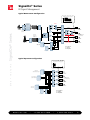
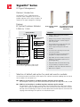
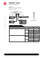
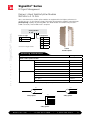
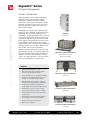
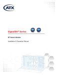
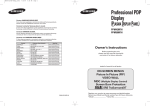
SignalOn® Series
RF Signal Management
Advanced broadband services are being developed and launched at an ever-accelerating
pace. While these services vary, they have one thing in common. Whether it be high-speed
data, video-on-demand, or IP telephony, broadband subscribers expect a reliable, high-quality
experience at an affordable price.
Spec Sheet
ADC’s SignalOn® Series has been designed with these demanding service requirements in mind.
This next generation RF signal management platform provides unmatched density, RF performance,
and reliability—all at a competitive price. With its patented hitless “make-before-break” attenuator
circuit design, maintaining your RF signal network has never been easier.
w w w.ad c.co m
•
+1-952-938-8080
•
1-800-366-3891
SignalOn® Series
RF Signal Management
Typical Downstream Configuration
Broadband CATV RF Spectrum
dB
freq
IRD Receiver
RFSM
IRD Receiver
A
IRD Receiver
S
IRD Receiver
C
IRD Receiver
S
SignalOn® Series
L-Band
Satellite
Splitters
QAM
modulators
IRD Receiver
IRD Receiver
C
A
IRD Receiver
Amplifiers
RFSM
Splitter
A
A
C
S
A
C
Receivers
processors
modulators
S
Fiber outside plant
to subscribers
C
A
C
S
A
C
Redundant Amplifiers
with RF Switch
S
CMTS for
HSD, VoIP
C = Combiner
S = Splitter
A = Amplifier
S
VOD servers
Typical Upstream Configuration
102721AE
Broadband CATV RF Spectrum
dB
freq
Network
diagnostics/test gear
S
A
S
A
S
A
S
A
5/08
•
QPSK set-top
control network
Fiber plant
from subscribers
CMTS for
HSD, VoIP
C = Combiner
S = Splitter
A = Amplifier
C
VOD servers
www.adc.com
•
+1-952-938-8080
•
1-800-366-3891
2
SignalOn® Series
RF Signal Management
Chassis
5/08
•
102721AE
SignalOn® Series
20-Position, 5 RU Chassis
32-Position, 4 RU Drawer
8-Position, 2 RU Chassis
Catalog Number
N - C __ __ __ __ B
Type
Power Kit
32D
32-position, Drawer
N
No
20V
20-position, Vertical
Y
Yes*
08H
8-position, Horizontal
* 20 and 8-position only
4-Position, 1 RU Chassis
04H 4-position, Horizontal
02H 2-position, Horizontal
2-Position, 1 RU Chassis
Ordering Information
Description
Catalog Number
Passive Chassis
32-position high-density chassis, 4 RU, black
N-C32DNB
20-position chassis, 5 RU, black
N-C20VNB
20-position chassis, 5 RU, NEBS
N-C20VN-NEBS
8-position chassis, 2 RU, black
N-C08HNB
8-position reversible chassis, 2 RU, black
N-C08HNB-R
4-position chassis, 1 RU, black
N-C04HNB
2-position chassis, 1 RU, black
N-C02HNB
Active Chassis
20-position powered chassis, 5 RU, black
N-C20VYB
20-position powered chassis, 5 RU, NEBS
N-C20VY-NEBS
8-position powered chassis, 2 RU, black
N-C08HYB
www.adc.com
•
+1-952-938-8080
•
1-800-366-3891
3
SignalOn® Series
RF Signal Management
Passives: Introduction
The SignalOn® Series, combined with the
innovative cable management of the chassis,
provides engineers with a variety of products to
simplify the RF signal management challenge.
Catalog Number
P
Make-Before-Break
Attenuation**
Plain splitter/
combiner
C
Combiner with
pad/monitor
S
Splitter with pad/
monitor
X
Splitter and
combiner with
pad/monitor (2 x
4:1 module only)
Connector Type
Pad and Monitor Module
with Make-Before-Break
Attenuation
Features
N - M __ __ __ __ __ __
Module Type
Plain Splitter/Combiner
Module
M0
0 dB default
M6
6 dB default
Configuration
12
2:1
14
4:1
18
8:1
32
3 x 2:1*
24
2 x 4:1*
• Industry's highest density with standard F
and BNC connectors
• Industry's best performance and specifications
• Individual performance certificate shipped
with every module
• Patented make-before-break attenuator pad
design for hitless signal balancing
• Chassis supports both passive and active
modules
• Clear chassis door provides protection and
clear view of modules
• Clear attenuator pad covers and patented
pad guides for simplified maintenance
• High quality, precision F or BNC connectors
F
F
• Designed to exceed NEBS requirements for
grounding/bonding
B
BNC
• Independent EMI near and far-field testing
*3 x 2:1 and 2 x 4:1 housed in a single module.
**Leave last two digits blank for plain modules.
• Ten year warranty on all passive modules
• Available in 1 RU, 2 RU, 4 RU and 5 RU chassis
• NEBS Level 3 compliant
5/08
•
102721AE
SignalOn® Series
Passives:
RF Splitter/Combiner Modules
5 MHz to 1 GHz
Selection of default pad option for pand and monitor modules
The make before break attenuation feature requires that a default attenuation padding value be chosen
for the module. The two options are:
M0 – 0 dB loss on the splitter or combiner leg when attenuator pad is removed
The M0 option is used in systems where the attenuator pad values will range from 0 dB to 10 dB.
M6 – 6 dB loss on the splitter or combiner leg when attenuator pad is removed
The M6 option is typically used in systems where the attenuator pad values range from 10 dB to
25 dB. In this situation, the additional 6 dB of loss that is placed in line when the pad is removed
will help to limit overdriving active devices further downstream and will help limit transmitter laser
clipping, and overdriving of RF amplifiers in the distribution plant.
www.adc.com
•
+1-952-938-8080
•
1-800-366-3891
4
SignalOn® Series
RF Signal Management
Ordering Information
Description
Catalog Number
Plain Splitter/Combiner Modules
BNC connector
N-MPB12
N-MPB14
8:1 plain
N-MPB18
3 x 2:1 plain
N-MPB32
2 x 4:1 plain
N-MPB24
2:1 plain
N-MPF12
4:1 plain
N-MPF14
8:1 plain
N-MPF18
3 x 2:1 plain
N-MPF32
0 dB default
N-MCB12M0
2:1 splitter with monitor
N-MSB12M0
2x4:1 combiner with monitor
N-MCB24M0
2x4:1 splitter with monitor
N-MSB24M0
2x4:1 splitter/combiner with monitor
N-MXB24M0
3x2:1 combiner with monitor
N-MCB32M0
3x2:1 splitter with monitor
N-MSB32M0
4:1 combiner with monitor
N-MCB14M0
4:1 splitter with monitor
N-MSB14M0
8:1 combiner with monitor
N-MCB18M0
8:1 splitter with monitor
N-MSB18M0
2:1 combiner with monitor
N-MCB12M6
2:1 splitter with monitor
N-MSB12M6
2x4:1 combiner with monitor
N-MCB24M6
2x4:1 splitter with monitor
N-MSB24M6
2x4:1 splitter/combiner with monitor
N-MXB24M6
3x2:1 combiner with monitor
N-MCB32M6
3x2:1 splitter with monitor
N-MSB32M6
4:1 combiner with monitor
N-MCB14M6
4:1 splitter with monitor
N-MSB14M6
8:1 combiner with monitor
N-MCB18M6
8:1 splitter with monitor
N-MSB18M6
102721AE
BNC connector
N-MPF24
2:1 combiner with monitor
•
2 x 4:1 plain
5/08
SignalOn® Series
F connector
2:1 plain
4:1 plain
6 dB default
www.adc.com
•
+1-952-938-8080
•
1-800-366-3891
5
SignalOn® Series
RF Signal Management
Ordering Information
Description
Catalog Number
Splitter/Combiner with Pad and Monitor Modules
0 dB default
SignalOn® Series
F connector
N-MCF12M0
2:1 splitter with monitor
N-MSF12M0
2x4:1 combiner with monitor
N-MCF24M0
2x4:1 splitter with monitor
N-MSF24M0
2x4:1 splitter/combiner with monitor
N-MXF24M0
3x2:1 combiner with monitor
N-MCF32M0
3x2:1 splitter with monitor
N-MSF32M0
4:1 combiner with monitor
N-MCF14M0
4:1 splitter with monitor
N-MSF14M0
8:1 combiner with monitor
N-MCF18M0
8:1 splitter with monitor
N-MSF18M0
2:1 combiner with monitor
N-MCF12M6
2:1 splitter with monitor
N-MSF12M6
2x4:1 combiner with monitor
N-MCF24M6
2x4:1 splitter with monitor
N-MSF24M6
2x4:1 splitter/combiner with monitor
N-MXF24M6
3x2:1 combiner with monitor
N-MCF32M6
3x2:1 splitter with monitor
N-MSF32M6
4:1 combiner with monitor
N-MCF14M6
4:1 splitter with monitor
N-MSF14M6
8:1 combiner with monitor
N-MCF18M6
8:1 splitter with monitor
N-MSF18M6
5/08
•
102721AE
6 dB default
2:1 combiner with monitor
www.adc.com
•
+1-952-938-8080
•
1-800-366-3891
6
SignalOn® Series
RF Signal Management
Passives:
Directional Coupler Modules
5 MHz to 1 GHz
Catalog Number
N - MD __ __ __ __ __
F
F
B
BNC
Application Type
R
Rear narrowcast signal port
DC Value
Circuit Quantity
09
9 dB
12 dB
Directional Coupler
1
Single circuit
12
3
Triple circuit
20
20 dB
V12
12 dB variable
Ordering Information
Description
Catalog Number
Directional Coupler Modules
BNC connector
9 dB
Triple circuit
N-MDB309R
12 dB
Single circuit
N-MDB112R
Triple circuit
N-MDB312R
6x variable
N-MDB6V12R
Single circuit
N-MDB120R
Triple circuit
N-MDB320R
9 dB
Triple circuit
N-MDF309R
12 dB
Single circuit
N-MDF112R
Triple circuit
N-MDF312R
6x variable
N-MDF6V12R
Single circuit
N-MDF120R
Triple circuit
N-MDF320R
20 dB
F connector
5/08
•
102721AE
SignalOn® Series
Connector Type
20 dB
www.adc.com
•
+1-952-938-8080
•
1-800-366-3891
7
SignalOn® Series
RF Signal Management
Passives: Conditioning and Monitor Modules
Features
SignalOn® Series
• Typically placed at the input to the forward
path optical transmitter, this module allows
for conditioning and grooming of the RF
signal gain and slope. It is designed as 1:1
input to output with two MBB circuits in
series for pad and EQ placement.
• -20 dB front facing monitor port
• NEBS Level 3 compliant
Triple C & M
F-Connectors
Ordering Information
Description
Catalog Number
Conditioning and Monitor Modules; triple circuit, 20 dB, 0 dB default
BNC connector
N-MMB320FM0
F connector
N-MMF320FM0
Attenuation
Pad
Equalization
(EQ) Pad
102721AE
In
Out
-20 dB
(monitor)
5/08
•
Conditioning and monitor module schematic
www.adc.com
•
+1-952-938-8080
•
1-800-366-3891
8
SignalOn® Series
RF Signal Management
Passives: L-Band Satellite Splitter Modules
950 MHz to 2.15 GHz
ADC’s new L-Band series satellite splitter modules are engineered for the highest performance in
the 950 MHz to 2.15 GHz frequency range. These plain splitter/combiner modules feature dual port
power-passing capability for powering LNB’s. All L-Band modules are available with precision F
or BNC connectors, and are NEBS Level 3 compliant.
Catalog Number
Connector Type
Configuration
F
F
12
2:1
B
BNC
14
4:1
18
8:1
32
3 x 2:1*
24
2 x 4:1*
*Housed in a single module.
L-Band
Satellite Splitter
Ordering Information
Description
Catalog Number
L-Band Satellite Splitter Modules
BNC connector
F connector
5/08
•
102721AE
SignalOn® Series
N - ML __ __ __
2:1 splitter
N-MLB12
4:1 splitter
N-MLB14
8:1 splitter
N-MLB18
3x2:1 splitter
N-MLB32
2x4:1 splitter
N-MLB24
2:1 splitter
N-MLF12
4:1 splitter
N-MLF14
8:1 splitter
N-MLF18
3x2:1 splitter
N-MLF32
2x4:1 splitter
N-MLF24
All L-Band modules feature dual port power passing capability.
Pass
Pass
1
Pass
2-Way Splitter
2
Pass
Pass
1
2
3
4
5
6
7
8
Pass
1
2
3
4
4-Way Splitter
8-Way Splitter
www.adc.com
•
+1-952-938-8080
•
1-800-366-3891
9
SignalOn® Series
RF Signal Management
Actives: Introduction
5/08
•
102721AE
SignalOn® Series
Today’s broadband services require high-quality
headend infrastructure that offers excellent
performance, reliability and design flexibility.
Furthermore, your infrastructure solution should
maximize the uptime of carrier-class services like
VoIP, VOD and HSD as applications evolve and
your network changes.
Leveraging over a decade of RF amplifier design
experience, ADC’s SignalOn® amplifiers have been
engineered to meet these demanding service
requirements. Featuring operation from 50 MHz to
1 GHz, the amplifiers offer excellent performance
and reliability. SignalOn amplifiers and associated
power supplies can be housed in the same chassis
as the SignalOn passive products for increased
design flexibility. With its electronically variable gain
and slope controls, you can adjust signal levels in
your network with no service downtime.
Amplifier
(front view)
SignalOn amplifiers feature non-service-affecting
gain and slope controls. This capability along with
the patented make-before-break attenuator pad
design of the splitters and combiners, allow for
"hitless" RF signal adjustment—critical for today's
carrier-class broadband service applications.
20-Position, 5 RU Powered Chassis
(with mixture of passive
and active modules)
Features
• Operation from 50 MHz to 1 GHz
• GaAs technology with near-100% surface
mount design for high performance
20-Position, 5 RU Powered Chassis
(rear view)
• Meets MIL-202 specs for quality and reliability
• Mounts in same SignalOn chassis as passive
modules for maximum design flexibility
• Digitally variable gain and slope control for
non-service-affecting signal level adjustments
• 20 dB monitor points on both input and
output signals for testing and troubleshooting
8-Position, 2 RU Powered Chassis
(front view)
• "Blind-mate" power bus connector with
gold-on-gold contacts; requires no cabling
• Chassis-mounted AC-DC and DC-DC power
supply options
• Redundant powering with dual load shared
power supplies for increased availability
• External +24 Vdc powering option
• NEBS Level 3 compliant
8-Position, 2 RU Powered Chassis
(rear view)
www.adc.com
•
+1-952-938-8080
•
1-800-366-3891
10
SignalOn® Series
Actives: Forward Path Amplifier
Actives: Amplifier Modules
Ordering Information
Description
Catalog Number
Forward Path Amplifier Modules
BNC connector
F connector
Performance Attribute
Bandwidth
Optimum RF input
Minimum full gain
Gain adjustment range
Tilt adjustment range
Gain flatness
Return loss,
input and output ports
N-MAB20FA
N-MAB30FA
20 dB
N-MAF20FA
30 dB
N-MAF30FA
20 dB Forward Amplifier
30 dB Forward Amplifier
50-1000 MHz
50-1000 MHz
+20 dBmV per channel
+10 dBmV per channel
20.0 dB
30.0 dB
10 +/-1 dB in 0.5 dB steps
10 +/-1 dB in 0.5 dB steps
10 +/-1 dB @ 50 MHz in 0.5 dB steps
10 +/-1 dB @ 50 MHz in 0.5 dB steps
+/- 0.4 dB from 50 to 870 MHz
+/- 0.5 dB from 870 to 1000 MHz
+/- 0.45 dB from 50 to 870 MHz
+/- 0.65 dB from 870 to 1000 MHz
-19.0 dB from 50 to 870 MHz
-16.5 dB from 870 to 1000 MHz
-18.0 dB from 50 to 870 MHz
-15.0 dB from 870 to 1000 MHz
7.3 dB from 50 to 870 MHz
7.6 dB from 870 to 1000 MHz
5.7 dB from 50 to 870 MHz
6.2 dB from 870 to 1000 MHz
CTB1
-73.1 dB
-78.9 dB
•
Noise figure
20 dB
30 dB
CSO1
-81.7 dB
-84.5 dB
5/08
102721AE
SignalOn® Series
Amplifier
(front view)
IMD1
-78.2 dB
-83.7 dB
Monitor ports
-20 dB test point for both RF input and RF output
Power dissipation
17W max
Operating temperature
0 - 50 degrees C
Dimensions
8.55"H x 1.67"W x 7.81"D
Power connector
gold-on-gold, slide-on contacts
Thermal shock
Meets MIL-STD-202 Method 107
Office vibration
Meets GR-63-Core Section 5.4.2
Mechanical shock
Meets MIL-STD-202 Method 213
Accelerated aging
Meets MIL-STD-202 Method 108
NEBS
Meets NEBS Level 3
Note: Measured with 110 channel loading and optimum RF input level at full gain and no tilt. Specifications are typical
worst-case numbers across the given frequency range, unless otherwise noted, and are subject to change without notice.
www.adc.com
•
+1-952-938-8080
•
1-800-366-3891
11
SignalOn® Series
RF Signal Management
Actives: Power Supply Modules
Power Supply
(front view)
SignalOn® Series
Ordering Information
Description
Catalog Number
Power Supply Modules
AC to DC
N-MVUVAC
DC to DC
N-MV48DC
Specifications
Performance Attribute
Input voltage
DC-DC
90-264 Vac, 50/60 Hz
36-72 Vdc nominal
Efficiency
75% nominal
80% nominal
Output voltage
24 Vdc ± 5%
24 Vdc ± 5%
Output power
200W (24 Vdc @ 8.33 Amps)
192W (24 Vdc @ 8 Amps)
Up to nine 30 dB amplifiers
Up to nine 30 dB amplifiers
Yes, dual load sharing
Yes, dual load sharing
Amplifiers supported
Redundancy
0 - 50° C
0 - 50° C
8.55"H x 1.67"W x 12.96"D
8.55"H x 1.67"W x 12.96"D
gold-on-gold, slide-on contacts
gold-on-gold, slide-on contacts
24 Vdc output test points
24 Vdc output test points
Field replaceable unit
Field replaceable unit
Alarm relays
Fan fail, output power fail
Fan fail, output power fail
•
Operating temperature
TTL contacts
Remote inhibit, input power
fail, output power fail
Remote inhibit, input power
fail, output power fail
5/08
102721AE
AC-DC
NEBS
Meets NEBS Level 3
Meets NEBS Level 3
Dimensions
Power connector
Test points
Fan
www.adc.com
•
+1-952-938-8080
•
1-800-366-3891
12
SignalOn® Series
RF Signal Management
Actives: RF Switch Modules
5/08
•
102721AE
SignalOn® Series
The ADC SignalOn® RF Switch Module (RFSM) is designed for use with the
SignalOn 8-position, or 20-position powered chassis. All RF connections to the
switch are made through standard 75 W BNC, or F connectors on the rear of the
module. All operating controls and indicators are located on the front panel with
configuration controls located on the rear of the module.
The primary function of the module is to monitor the RF signal gain of the operating
primary “A“ input, and switch to the backup “B“ input if the gain of the primary
path rises, or falls below the pre-set customer selected threshold. Should the “A“
input side go above, or fall below the threshold of the unit, the RFSM will rapidly
switch the input from the failed input to the secondary input. This switch usually
is less that 10 milliseconds. Switch status, failure LEDS, and RF level bar graphs are
mounted on the front panel of the switch module. Switching threshold: +/- 3 dB or
+/- 6 dB, and alarm contact closures are located on the rear of module.
Dual RF Switch
Module
Features
• Continuous monitoring of primary and secondary
• Detects both high and low power failures
• E asily configured for redundancy or A-B
switch applications
• U
ser-selectable switching threshold:
+/- 3 dB or +/- 6 dB
• F ront panel bar graph display provides indication
of RF power and switching threshold
• Fail-over switching time < 10 ms
• Indication of switch status provided by front
panel LED and rear terminal block contacts
• Automatic switchback after "A" path is restored
• E asily configured switching threshold levels via
rear DIP switch
• F ront-panel LED status and dual power
level displays
• One-step calibration
• Alarm contact for remote failure monitoring
• Auto switch-back feature to primary input
• Available in BNC and F-connector configurations
• Built-in delay to prevent from false switching
• Single or dual modules
• Automatic or manual modes of operation
• NEBS Level 3 compliant
Ordering Information
Description
Catalog Number
Redundant RF Switch Modules
BNC connector
F connector
www.adc.com
•
Single circuit
N-MRFSM1-B
Dual circuit
N-MRFSM2-B
Single circuit
N-MRFSM1-F
Dual circuit
N-MRFSM2-F
+1-952-938-8080
•
1-800-366-3891
13
SignalOn® Series
RF Signal Management
Actives: Reverse Path Amplifier Modules
Reverse Path Amplifier
To mount modules in SignalOn chassis use these
amplifiers in conjunction with N-ACC-BRKT-RA
(mounts 1 or 2 amps) – see page 16.
Features
• Fixed 22 dB
• Low distortion characteristics
• Low noise figure
• 5-200 MHz bandwidth
• Two 20 dB monitor ports (input and output)
• BNC or F connectors
• AC or DC powering
• Power redundancy (optional)
Ordering Information
Description
Dimensions (H x W x D)
Reverse Path Amplifier Modules
22 dB Fixed Gain
BNC connectors
F connectors
57 mm x 31 mm x 203 mm
(2.25" x 1.2" x 8.0")
Catalog Number
RFX-AMP-22B
RFX-AMP-22F
5/08
•
102721AE
SignalOn® Series
ADC’s Return Path Amplifier was designed
specifically to solve problems particular to your
environment. Providing greater density, unparalleled
cable management, greater functionality and
redundant powering, the return path amplifier
is part of the system approach to integrating all
signal management functions in a common format
and modular system.
www.adc.com
•
+1-952-938-8080
•
1-800-366-3891
14
SignalOn® Series
RF Signal Management
Accessories
Ordering Information
Description
Catalog Number
Cable Management Kits; (includes rack mount cable management rings)
2 brackets, 2 – 2.5" x 5.5" cable rings
N-ACMK-01P
4 brackets, 4 – 2.5" x 5.5" cable rings
N-ACMK-04P
5/08
•
102721AE
SignalOn® Series
Chassis Extender Brackets for;
2-position chassis, 23" rack
EB-17B
8-position chassis, 23" rack
EB-35B
20-position chassis, ETSI 21" rack
EB-87B
Insertion/Withdrawal Tools
BNC insertion tool with 12" handle
BT2000-12
BNC insertion tool with 24" handle
BT2000-24
F connector insertion tool
SC-FG
Terminating Plugs
BNC terminating plug, 75 W ± 1.0%
BNC-TP1
BNC high-performance terminating plug, 75 W ± .1%
BNC-TP2
F terminating plug, 75 W ± 1.0%
CF-TP1
F high-performance terminating plug, 75 W ± .1%
CF-TP2
Attenuator Pads
XX dB pads, qty 25 (replace XX with 00 through 26)
N-ACC-AP-XX
1-5 dB pads, 5 of each pad value, total qty 25
N-ACC-AP-S1
6-10 dB pads, 5 of each pad value, total qty 25
N-ACC-AP-S2
11-15 dB pads, 5 of each pad value, total qty 25
N-ACC-AP-S3
16-20 dB pads, 5 of each pad value, total qty 25
N-ACC-AP-S4
21-25 dB pads, 5 of each pad value, total qty 25
N-ACC-AP-S5
3,6,9,12,15 dB pads, 5 of each pad value, total qty 25*
N-ACC-AP-M0
0,3,9,12,15 dB pads, 5 of each pad value, total qty 25**
N-ACC-AP-M6
75 W termination pads, qty 25
N-ACC-TP-75
* Kit intended for 0 db default MBB modules (-M0 modules)
** Kit intended for 6 db default MBB modules (-M6 modules)
BNC Terminating Plugs
(BNC TP-1 and TP-2)
www.adc.com
•
+1-952-938-8080
F Terminating Plugs
(CF TP-1 and TP-2)
•
1-800-366-3891
15
SignalOn® Series
Accessories
Ordering Information
Description
Catalog Number
Equalizer Pads
2 dB plug-in
N-ACC-LE-02
3 dB plug-in
N-ACC-LE-03
4 dB plug-in
N-ACC-LE-04
5 dB plug-in
N-ACC-LE-05
6 dB plug-in
N-ACC-LE-06
7 dB plug-in
N-ACC-LE-07
8 dB plug-in
N-ACC-LE-08
9 dB plug-in
N-ACC-LE-09
10 dB plug-in
N-ACC-LE-10
11 dB plug-in
N-ACC-LE-11
12 dB plug-in
N-ACC-LE-12
13 dB plug-in
N-ACC-LE-13
DC Power Upgrade Kits for;
2 RU chassis – used to power 8-position
N-ACC-PWRKIT-08B
5 RU chassis – used to power 20-position
N-ACC-PWRKIT-20B
Power Supply Accessories
Power cord for power supply
N-ACC-CBL-DC-DC
Fan replacement kit for power supply
N-ACC-FAN
Module Conversion Kits; to install
1 RF Worx® passive module into SignalOn® chassis
N-ACC-BRKT-RFW
2 RF Worx reverse amps into powered SignalOn chassis
®
N-ACC-BRKT-RA
1 SignalOn passive module into MAXNET chassis
N-AMCK-01
18 SignalOn® passive modules into MAXNET™ chassis1
N-AMCK-18
®
Spec Sheet
®
™
1
Blank Module Covers
Single blank panel cover
N-ACC-BLANK-01
Dual blank panel cover
N-ACC-BLANK-02
Bulkhead Testpoint Panels
1
Single panel with 2 F-81 bulkhead connectors
N-MTPF2
Single panel with 2 F-81 bulkhead connectors
N-MTPF6
MAXNET is a trademark of ATX Networks
Website: www.adc.com
From North America, Call Toll Free: 1-800-366-3891 • Outside of North America: +1-952-938-8080
Fax: +1-952-917-3237 • For a listing of ADC’s global sales office locations, please refer to our website.
ADC Telecommunications, Inc., P.O. Box 1101, Minneapolis, Minnesota USA 55440-1101
Specifications published here are current as of the date of publication of this document. Because we are continuously
improving our products, ADC reserves the right to change specifications without prior notice. At any time, you may
verify product specifications by contacting our headquarters office in Minneapolis. ADC Telecommunications, Inc.
views its patent portfolio as an important corporate asset and vigorously enforces its patents. Products or features
contained herein may be covered by one or more U.S. or foreign patents. An Equal Opportunity Employer
102721AE 5/08 Revision © 2008, 2006 ADC Telecommunications, Inc. All Rights Reserved