1
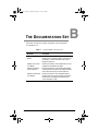
1061.book Page i Wednesday, May 29, 2002 8:59 AM
Campus
CAMPUS-RS LINE UNIT
USER MANUAL
Campus-RS
LINE UNIT
HDSL
TEST
PORT
RS-232
CONSOLE
1061.book Page ii Wednesday, May 29, 2002 8:59 AM
Copyright
May 29, 2002
© 2002 ADC DSL Systems, Inc. All rights reserved.
Trademark Information
ADC is a registered trademark of ADC Telecommunications, Inc. Avidia, Megabit
Modem, Campus-384, Campus-768, Campus-E1, Campus-REX, Campus-Star, and
Campus-T1 are registered trademarks and Campus-RS, StarGazer, SwitchWare, and
Skyrocket are trademarks of ADC DSL Systems, Inc.Other product names mentioned
in this installation guide are used for identification purposes only and may be
trademarks or registered trademarks of their respective companies.
Other product names mentioned in this document are used for identification purposes
only and may be trademarks or registered trademarks of their respective companies.
Disclaimer of Liability
Information contained in this document is company private to ADC DSL Systems, Inc.,
and shall not be modified, used, copied, reproduced or disclosed in whole or in part
without the written consent of ADC.
Contents herein are current as of the date of publication. ADC reserves the right to
change the contents without prior notice. In no event shall ADC be liable for any
damages resulting from loss of data, loss of use, or loss of profits, and ADC further
disclaims any and all liability for indirect, incidental, special, consequential or other
similar damages. This disclaimer of liability applies to all products, publications and
services during and after the warranty period.
ii
May 29, 2002
Campus-RS Line Unit User Manual
1061.book Page iii Wednesday, May 29, 2002 8:59 AM
FCC Class A Compliance
FCC CLASS A COMPLIANCE
This equipment has been tested and found to comply with the limits for a
Class A digital device, pursuant to Part 15 of the FCC Rules. These limits are
designed to provide reasonable protection against harmful interference when
the equipment is operated in a commercial environment. This equipment
generates, uses, and can radiate radio frequency energy and, if not installed
and used in accordance with the instruction manual, may cause harmful
interference to radio communications. Operation of this equipment in a
residential area is likely to cause harmful interference in which case the user
will be required to correct the interference at his own expense.
Campus-RS Line Unit User Manual
May 29, 2002
iii
1061.book Page iv Wednesday, May 29, 2002 8:59 AM
Using This Manual
USING THIS MANUAL
This manual provides information on how to:
•
locate the features of the ADC® Campus-RS™ Line Unit (150-1159-51)
•
install the line unit into a Campus-Star® chassis (CACNS700 or
CARS-51)
•
set up the line unit
•
contact ADC for assistance
DOCUMENT CONVENTIONS
Two types of messages, identified by icons, appear in the text.
Notes contain information about special circumstances.
Cautions indicate the possibility of equipment damage or the
possibility of personal injury.
This manual uses the following conventions:
iv
•
This font indicates text that appears on the LCD or terminal.
•
Keycaps, such as
keyboard.
•
Names in bold font indicate buttons on the desktop unit or line unit that
you press.
ENTER ,
indicate keys that you press on the terminal
May 29, 2002
Campus-RS Line Unit User Manual
1061.book Page v Wednesday, May 29, 2002 8:59 AM
Unpack and Inspect the Shipment
UNPACK AND INSPECT THE SHIPMENT
Upon receipt of the shipment:
1
Unpack the card and inspect it for signs of damage. If it has been
damaged in transit, report the extent of the damage to the transportation
company and to ADC immediately. Order replacement equipment if
necessary.
2
Compare the contents of the package against the packing list to ensure a
complete and accurate shipment. If the shipment is incomplete or
incorrect, contact ADC as described in Appendix C, “Product Support.”
If you need to store the unit for several days or more before installing it, return
it to the original packaging.
Campus-RS Line Unit User Manual
May 29, 2002
v
1061.book Page vi Wednesday, May 29, 2002 8:59 AM
Unpack and Inspect the Shipment
vi
May 29, 2002
Campus-RS Line Unit User Manual
1061.book Page vii Wednesday, May 29, 2002 8:59 AM
Table of Contents
TABLE OF CONTENTS
Chapter 1: About the Product ____________________________________ 1
Features of the Line Unit ......................................................... 3
HDSL Reach and Transmission Rate ...................................... 5
Chapter 2: Installing and Configuring the Line Unit__________________ 9
Surge Protection....................................................................... 9
Install the Line Unit ............................................................... 10
Complete System Installation ................................................ 11
Determine the HDSL Operating Mode .................................. 12
Set the HDSL Operating Mode and Transmission Rate ........ 12
Standard Mode Configuration ................................. 14
Extended Mode Configuration ................................ 14
Set the HDSL Transceiver Mode ........................................... 15
Operating with Earlier Versions of Campus Products ........... 15
Appendix A: Technical Specifications _____________________________ 17
Appendix B: The Documentation Set _____________________________ 19
Appendix C: Product Support ___________________________________ 21
Campus-RS Line Unit User Manual
May 29, 2002
vii
1061.book Page viii Wednesday, May 29, 2002 8:59 AM
Table of Contents
viii
May 29, 2002
Campus-RS Line Unit User Manual
1061.book Page 1 Wednesday, May 29, 2002 8:59 AM
ABOUT THE PRODUCT
1
The Campus-RS™ (Rate Selectable) Line Unit, mated with an RS interface
card in a Campus-Star chassis, comprises half of a High-bit-rate Digital
Subscriber Line (HDSL) transmission system. When connected to another
Line Unit installed in a Campus-Star® chassis or to a Campus-RS Desktop
Unit, the Line Unit can transport digitized voice, data, and video signals over
existing copper wire at a number of different HDSL transmission rates.
The interface card mated to the Line Unit determines the
HDSL transmission rates available. Some cards may support
fewer rates or only one rate. See the manual for the interface
card to determine the available HDSL transmission rates for
the system.
The Campus-RS system is compatible, over the HDSL link, with earlier
versions of Campus products. You can connect the Campus-RS Line Unit,
through the HDSL link, to a Campus-E1®, Campus-T1®, or Campus-768®
Desktop Unit or Line Unit. The Campus-RS system is not compatible with
Campus-384® Desktop Units or Line Units.
All earlier versions of Campus products are manufactured to operate at a
single HDSL transmission rate. To establish an HDSL link with an earlier
product, the Campus-RS standard HDSL Operating Mode supports three
preset transmission rates:
•
2.048 Mbps (E1)
•
1.544 Mbps (T1)
•
768 kbps
Campus-RS Line Unit User Manual
1
1061.book Page 2 Wednesday, May 29, 2002 8:59 AM
About the Product
When connecting to another Campus-RS unit, the three standard HDSL
transmission rates are available. In addition, the Campus system can be
configured to support an extended HDSL Operating Mode, as follows:
•
Over a single-loop connection, the Line Unit supports rates from 64 kbps
to 2304 kbps in 64 kbps increments, depending on the interface card.
•
Over a dual-loop connection, the Line Unit supports rates from 256 kbps
to 4608 kbps in 128 kbps increments, depending on the interface card.
While the Line Unit supports all the rates listed above, the
actual rates available depends on the interface card installed
in the Line Unit. For example, the Campus Fractional Interface
Card support the full range of transmission rates, while the
CSU/DSX-1 Interface Card only supports the T1 standard rate.
The User Manual for the Interface Card provides a list of rates
supported by the card.
The transmission rate you select depends on the type of copper infrastructure
and the physical layout of the network. The extended HDSL Operating
Modes provide a way to make trade-offs between the reach of the HDSL line
and the transmission rate.
The default setting for the HDSL Operating Mode depends upon the interface
card. If necessary, change the HDSL Operating Mode and associated
parameters through the system configuration menus. Instructions for using
the menus are in the User Manual for the interface card mated with the
Line Unit.
2
May 29, 2002
Campus-RS Line Unit User Manual
1061.book Page 3 Wednesday, May 29, 2002 8:59 AM
About the Product
FEATURES OF THE LINE UNIT
This illustration shows the front of the Campus-RS Line Unit and Table 1 on
page 4 describes its features.
Campus-RS
LINE UNIT
HDSL
TEST
PORT
Status
LEDs
RS-232
port
RS-232
CONSOLE
Retaining
latch
Campus-RS Line Unit User Manual
May 29, 2002
3
1061.book Page 4 Wednesday, May 29, 2002 8:59 AM
About the Product
Table 1. Campus-RS Line Unit Features
Feature
Function
HDSL LED
Indicates the status of the HDSL link. The LED:
flashes green to indicate that the Line Unit has detected a
remote unit and is attempting to establish the HDSL link
lights solid green to indicate that the HDSL link is active with
no alarms
flashes red to indicate a major alarm (the link is down)
lights solid red to indicate a minor alarm
flickers red to indicate an acknowledged alarm (a)
Test LED
Indicates the presence of a test or loopback condition. The LED:
lights solid amber to indicate a loopback condition
flashes amber to indicate a test condition
Port LED
Indicates the status of the data port. The LED:
lights solid green to indicate no alarms
flashes red to indicate a major alarm
lights solid red to indicate a minor alarm
flickers red to indicate an acknowledged alarm (a)
RS-232 Console Port
Provides a connection to an ASCII terminal to configure and
monitor the Campus-RS system.
Retaining Latch
Secures the Line Unit into place when the unit is installed in a
Campus-Star chassis
Bar code and warranty
control labels
Located on the right side of the line unit, with the unit held as in
the previous illustration, these labels provide important
information if you need to contact ADC for technical support.
(a) To acknowledge a minor alarm, press and hold the Escape button on the Campus
Management Unit (CMU) for three seconds.
4
May 29, 2002
Campus-RS Line Unit User Manual
1061.book Page 5 Wednesday, May 29, 2002 8:59 AM
About the Product
HDSL REACH AND TRANSMISSION RATE
Four factors determine the maximum transmission rate and loop length of the
HDSL line:
•
the wire gauge of the line
•
the condition of the line (presence of bridge taps, splices, and so on)
•
whether the line uses one or two loops
•
the amount of noise on the line
The following charts show the maximum loop length over the range of HDSL
transmission rates for 26 AWG (.40 mm), 24 AWG (.51 mm), 22 AWG
(.61 mm), and 19 AWG (.91 mm), respectively. The shaded area on each
chart shows a range of expected maximum loop lengths that will provide a bit
error rate (BER) of greater than 5E-8:
•
The best case (longest reach) is measured in a noiseless environment.
•
The worst case is measured using an industry-standard noise model that
simulates the cable pair in a bundle with 49 other cable pairs each
transmitting with similar frequency characteristics.
The actual reach will fall somewhere between these two cases, and will vary
according to such factors as the condition of the loop pairs, the presence of
bridge taps, splices, line noise, and so on.
Depending upon the desired data rate and wire gauge,
two-loop operation provides between 12% and 47% greater
reach than one loop operation at the same data rate. For
example, for a 24 AWG loop, a unit configured for two-loop
operation at 1152 kbps will have a maximum reach of
approximately 4.6 miles, whereas a one-loop configuration
at 1152 kbps will have a maximum reach of approximately
3.0 miles.
Campus-RS Line Unit User Manual
May 29, 2002
5
1061.book Page 6 Wednesday, May 29, 2002 8:59 AM
About the Product
Campus-RS, Maximum Reach vs Rate
26 AWG (0.40 mm)
8.00
25.0
7.00
Reach (km)
5.00
15.0
4.00
10.0
3.00
Reach (kft)
20.0
6.00
2.00
5.0
1.00
2304/4308
2048/4096
1792/3584
1536/3072
1280/2560
1024/2048
768/1536
384/768
0.0
128/256
0.00
Data Rate, One Loop/Two Loops
(kbps)
Campus-RS, Maximum Reach vs Rate
24 AWG (0.51 mm)
10.00
30.0
9.00
25.0
7.00
20.0
6.00
5.00
15.0
4.00
Reach (kft)
Reach (km)
8.00
10.0
3.00
2.00
5.0
1.00
2304/4308
2048/4096
1792/3584
1536/3072
1280/2560
1024/2048
768/1536
384/768
0.0
128/256
0.00
Data Rate, One Loop / Two Loops
(kbps)
6
May 29, 2002
Campus-RS Line Unit User Manual
1061.book Page 7 Wednesday, May 29, 2002 8:59 AM
About the Product
Campus-RS, Maximum Reach vs Rate
22 AWG (0.51 mm)
16.00
50.0
14.00
Reach (km)
10.00
30.0
8.00
20.0
6.00
Reach (kft)
40.0
12.00
4.00
10.0
2.00
0.0
2304/4308
2048/4096
1792/3584
1536/3072
1280/2560
1024/2048
768/1536
384/768
128/256
0.00
Data Rate, One Loop / Two Loops
(kbps)
Campus-RS, Maximum Reach vs Rate
19 AWG (0.51 mm)
25.00
80.0
70.0
20.00
50.0
15.00
40.0
10.00
30.0
Reach (kft)
Reach (km)
60.0
20.0
5.00
10.0
2304/4308
2048/4096
1792/3584
1536/3072
1280/2560
1024/2048
768/1536
384/768
0.0
128/256
0.00
Data Rate, One Loop / Two Loops
(kbps)
Campus-RS Line Unit User Manual
May 29, 2002
7
1061.book Page 8 Wednesday, May 29, 2002 8:59 AM
About the Product
8
May 29, 2002
Campus-RS Line Unit User Manual
1061.book Page 9 Wednesday, May 29, 2002 8:59 AM
INSTALLING AND
CONFIGURING
THE LINE UNIT
2
This chapter describes how to install the Campus-RS Line Unit and its
corresponding interface card into a Campus-Star, and how to set up the HDSL
link.
Make sure the interface card you mate with the Line Unit is
a Campus-RS interface card. The Campus-RS Line Unit is not
compatible with previous versions of Campus interface
cards.
SURGE PROTECTION
To protect you and your Campus-RS devices, ADC recommends the use of a
dual line Network Interface Device (NID) with a gas tube or solid state
composition. The NID can protect both Campus-Star chassis and Campus-RS
Desktop Units.
Most lines leased from your local telephone company already
have protection devices installed. Contact your telephone
company to see if your lines require additional protection.
For surge protection:
•
the maximum recommended breakdown voltage should not exceed
300 Vdc
•
carbon based protection devices are not recommended
•
data line surge protectors can also be used
Campus-RS Line Unit User Manual
9
1061.book Page 10 Wednesday, May 29, 2002 8:59 AM
Installing and Configuring the Line Unit
Install the NID on the HDSL line between the HDSL jack and the Telephone
Company (Telco) demarcation point.
Telco demarcation point
HDSL line port
NID
HDSL
jack
Campus-RS Unit
HDSL line
ADC also suggests providing power line protection for critical circuits in high
lightning areas. Use conditioned AC voltage, furnished through an
Uninterruptible Power Supply (UPS), that is bonded to a good facilities
ground. This provides additional protection against voltage transients
entering through the power lines.
INSTALL THE LINE UNIT
To install the Line Unit:
1
Install the interface card into the back of the Campus-Star chassis,
following the instructions in the User Manual for the card.
Make sure you install the interface card before the line unit.
Installing the card with the line unit already installed may
cause damage to the card, the line unit, or both.
2
10
Ensure that the retaining latch is pulled completely forward and down.
May 29, 2002
Campus-RS Line Unit User Manual
1061.book Page 11 Wednesday, May 29, 2002 8:59 AM
Installing and Configuring the Line Unit
CM
U-7
10
PO
W
MA
NA
GE
ME
NT
UN
IT
ER
SL
OT
Campus-RS
Line Unit
AL
AR
MS
MA
MINJOR
AC OR
O
Ca
mp
LIN us H
R
E
UN A
IT
HD
SL
TE
ST
PO
RT
Ca
mp
LIN us H
R
E
UN A
IT
HD
SL
TE
ST
PO
RT
Ca
mp
LIN us H
R
E
UN A
IT
RE
SE
T
Ca
mp
LIN us H
R
E
UN A
IT
HD
SL
TE
ST
PO
RT
RS
CO -232
NS
OLE
RS
CO -232
NS
OLE
HD
SL
RS
CO -232
NS
OLE
TE
ST
PO
RT
RS
CO -232
NS
OLE
Campus-Star
chassis
3
Slide the Line Unit into the slot on the front of the Campus-Star chassis
that corresponds to the slot into which you installed the interface card.
Use the guide rails to align the card.
4
When the Line Unit is in as far as possible, push the retaining latch in
until it snaps into place. Assuming the Campus-Star power is on, the Line
Unit performs a power-on test. After completing the test, the HDSL LED
flashes red.
COMPLETE SYSTEM INSTALLATION
To complete the installation of the Campus-RS system and ready it for use:
1
Install the remote unit. This may be an interface card installed in a
Campus Desktop Unit or an interface card and line unit installed in
another Campus-Star chassis.
2
Connect the cables according to the instructions in the Campus-Star or
Campus-RS Desktop Unit documentation.
Campus-RS Line Unit User Manual
May 29, 2002
11
1061.book Page 12 Wednesday, May 29, 2002 8:59 AM
Installing and Configuring the Line Unit
DETERMINE THE HDSL OPERATING MODE
The Campus-RS Line Unit supports two operating modes:
•
Standard Mode provides HDSL compatibility with earlier versions of
Campus products, such as the Campus-T1 Desktop Unit.
•
Extended Mode provides a wide range of HDSL transmission rates when
the Line Unit is connected to another Campus-RS product.
The following illustration shows the operating modes available for the
possible Campus system configurations.
Two pairs
Standard Mode
Campus-RS
Standard Mode
Campus-RS
* Standard Mode or
Extended Mode
Campus-RS
Legacy Campus-T1/E1
One pair
Legacy Campus-768
One or two pairs
Campus-RS
* Depends on: Interface card capabilities, available/desired number of pairs, reach requirements.
12
May 29, 2002
Campus-RS Line Unit User Manual
1061.book Page 13 Wednesday, May 29, 2002 8:59 AM
Installing and Configuring the Line Unit
SET THE HDSL OPERATING MODE AND
TRANSMISSION RATE
This section provides generic instruction for setting the HDSL Operating
Mode and transmission rate. The actual steps depend on the interface card
mated with the Line Unit. Refer to the manual for the interface card for a
description of configuration options and complete configuration instructions.
LCD display
Slot selection control pad
CMU-710 MANAGEMENT UNIT
System alarm LEDs
SLOT
ALARMS
MAJOR
MINOR
ACO
NEXT
ENTER
ESC
POWER
RS-232
RESET
Menu buttons
Console port
Reset button
The steps in this section use the menu buttons and LCD on the Campus-Star’s
Campus Management Unit (CMU). To set the HDSL Transmission Rate:
1
Use the Slot selection buttons to select the slot in which you installed the
Line Unit. The LCD displays:
MARGIN (LOC/RMT)
1:XX/XX 2:XX/XX
2
Press Escape four times to go to the top level menu.
3
Press Next until HDSL LINK CONFIG & STATUS displays, then press
Enter.
4
Continue with one of the following sections, depending on whether you
are using Standard Mode or Extended Mode.
Campus-RS Line Unit User Manual
May 29, 2002
13
1061.book Page 14 Wednesday, May 29, 2002 8:59 AM
Installing and Configuring the Line Unit
Standard Mode Configuration
This section continues from Step 4 in the previous section to set a standard
HDSL transmission rate.
1
If the Operating Mode is set to STANDARD, skip to Step 3. Otherwise,
press Enter.
2
Press Next until STANDARD displays, then press Enter. The LCD
displays OPERATING MODE.
3
Press Next until HDSL RATE displays, then press Enter.
4
Press Next until the desired HDSL transmission rate displays, then
press Enter.
To continue setting up the system, proceed to the “Set the HDSL Transceiver
Mode” section.
Extended Mode Configuration
This section continues from Step 4 on page 13 to set an extended HDSL
transmission rate.
1
If the Operating Mode is set to EXTENDED, skip to Step 3. Otherwise,
press Enter.
2
Press Next until EXTENDED displays, then press Enter. The LCD
displays OPERATING MODE.
3
Press Next until LOOP MODE displays, then press Enter.
4
Press Next to display either 2 LOOPS or 1 LOOP, then press Enter to
select the option displayed. The LCD displays LOOP MODE.
5
Press Next until HDSL RATE displays, then press Enter.
6
Press Next until the desired HDSL transmission rate displays, then
press Enter.
To continue setting up the system, proceed to the “Set the HDSL Transceiver
Mode” section.
14
May 29, 2002
Campus-RS Line Unit User Manual
1061.book Page 15 Wednesday, May 29, 2002 8:59 AM
Installing and Configuring the Line Unit
SET THE HDSL TRANSCEIVER MODE
The Transceiver Mode option determines the hierarchy of the two Campus
units when attempting to establish an HDSL link. There are three settings:
•
If a unit is set to Master, it initiates the HDSL link. The other Campus
unit must be set to Slave or Auto.
•
If a unit is set to Slave, it waits for the other Campus unit to initiate the
HDSL link. The other unit must be set to Master or Auto.
•
If a unit is set to Auto, it automatically switches between Master and
Slave until an HDSL link is established. The setting of the other Campus
unit is irrelevant. This is the default setting.
The default setting of Auto Mode is the recommended setting, regardless of
the setting of the remote unit. To determine the current Transceiver Mode, or
to change the setting:
1
Press Escape four times to go to the top level menu.
2
Press Next until HDSL LINK CONFIG & STATUS displays.
3
Press Enter. OPERATING MODE displays.
4
Press Next until XCVR MODE displays, along with the current setting.
5
To change the setting, press Enter.
6
Press Next to scroll through the Transceiver Mode options until the
desired setting displays.
7
Press Enter to select the displayed setting. The LCD displays XCVR
MODE and the current setting.
Campus-RS Line Unit User Manual
May 29, 2002
15
1061.book Page 16 Wednesday, May 29, 2002 8:59 AM
Installing and Configuring the Line Unit
OPERATING WITH EARLIER VERSIONS OF
CAMPUS PRODUCTS
Campus-RS Desktop and Line Units are fully compatible with most of the
earlier versions of Campus products, including Campus-E1, Campus-T1, and
Campus-768. The Campus-RS Desktop and Line Units are not currently
compatible with Campus-384 products.
Furthermore, if a Campus-RS unit is connected over an HDSL link to an
earlier Campus product, and if either unit has the HDSL Transceiver (XCVR)
Mode set to AUTO, the HDSL link may not operate properly.
When operating the Campus-RS product with an earlier version of the
Campus products, to avoid any problems with link startup or operation, it is
recommended that the Transceiver Mode be set as follows:
•
Campus-RS = MASTER
•
Campus E1/T1/768 = SLAVE
If one or both units are already set to AUTO and the HDSL link is active,
disconnect the HDSL link, change the settings as recommended, and
reconnect the link. This will assure the link integrity on any subsequent
startups.
This situation does not apply to a circuit with two Campus-RS
units. You may leave the units set to their default setting of
AUTO, and they will operate properly.
16
May 29, 2002
Campus-RS Line Unit User Manual
1061.book Page 17 Wednesday, May 29, 2002 8:59 AM
TECHNICAL
SPECIFICATIONS
A
HDSL Line
Signal Format
E1
Full Duplex 1040 kbps
2B1Q Line Code (two pair)
T1 (default)
Full Duplex 784 kbps
2B1Q Line Code (two pair)
768
Full Duplex 784 kbps
2B1Q Line Code (one pair)
Transmit Signal Power
+13.5dBm (±1dBm)
Console Connector
RJ-45
Return Loss
20dB, 40 kHz to 200 kHz
Loop Provisioning Loss
E1
35dB at 260 kHz at 135Ω
T1
35dB at 196 kHz at 135Ω
768
35dB at 196 kHz at 135Ω
One-Way Transmission Delay
Less than 300 microseconds
Physical
Height
5.94 inches (15.09 cm)
Width
4.63 inches (11.76 cm)
Depth
1.19 inches (3.02 cm)
Weight
0.4 pounds (0.18 kg)
Campus-RS Line Unit User Manual
17
1061.book Page 18 Wednesday, May 29, 2002 8:59 AM
Technical Specifications
Electrical Power Input
5 Vdc
Environmental
Operating Temperature
32 to 122°F (0° to 50° C)
Relative Humidity
0 to 85%
Electromagnetic Emissions
Safety Compliance
Per FCC Part 15 Class A, CE
UL, CSA, CE
ADC reserves the right to change features and specifications without notice.
18
May 29, 2002
Campus-RS Line Unit User Manual
1061.book Page 19 Wednesday, May 29, 2002 8:59 AM
THE DOCUMENTATION SET
B
This table describes the manuals and guides in the Campus-RS
documentation set.
Table 2.
Campus-RS Documentation Set
Document
Description
Campus-Star User
Manual
Contains instructions for setting up and using a
Campus-Star. The manual includes instructions for
installing Line Units and interface cards into the
Campus-Star chassis.
Campus-RS Line Unit
User Manual
Describes the features of the Campus-RS Line Unit
and provides installation instructions.
Campus-RS Desktop
Unit User Manual
Describes the features of the Campus-RS Desktop
Unit and provides instructions for installing interface
cards, and connecting the unit to an HDSL line.
Campus Interface Card
User Manuals
Describes the features of the individual Campus
interface cards, one card per manual, and contains
instructions for configuring and monitoring the
system through the cards.
Campus-RS Line Unit User Manual
19
1061.book Page 20 Wednesday, May 29, 2002 8:59 AM
The Documentation Set
20
May 29, 2002
Campus-RS Line Unit User Manual
1061.book Page 21 Wednesday, May 29, 2002 8:59 AM
CONTACTING ADC
C
ADC Customer Service Group provides expert pre-sales and post-sales
support and training for all its products. Technical support is available 24
hours a day, 7 days a week by contacting the ADC Technical Assistance
Center (TAC).
Sales Assistance
800.366.3891 extension 73000
(USA and Canada)
952.917.3000
Fax: 952.917.3237
• Quotation Proposals
Systems Integration
800.366.3891, extension 73000
(USA and Canada)
952.917.3000
• Complete Solutions (from concept to
installation)
• Ordering and Delivery
• General Product Information
• Network Design and Integration Testing
• System Turn-Up and Testing
• Network Monitoring (upstream or
downstream)
• Power Monitoring and Remote Surveillance
• Service/Maintenance Agreements
• Systems Operation
ADC Technical Assistance Center
800.638.0031
714.730.3222
Fax: 714.730.2400
Email: [email protected]
• Technical Information
• System/Network Configuration
• Product Specification and Application
• Training (product-specific)
• Installation and Operation Assistance
• Troubleshooting and Repair/Field Assistance
Campus-RS Line Unit User Manual
21
1061.book Page 22 Wednesday, May 29, 2002 8:59 AM
Contacting ADC
Online Technical Support
• www.adc.com/Knowledge_Base/index.jsp
Online Technical Publications
• www.adc.com/library1/
Product Return Department
800.366.3891 ext. 73748 or
952.917.3748
Fax: 952.917.3237
Email: repair&[email protected]
• ADC Return Material Authorization (RMA)
number and instructions must be obtained
before returning products.
All telephone numbers with an 800 prefix are toll-free in the USA and Canada.
22
May 29, 2002
Campus-RS Line Unit User Manual
1061.book Page 23 Wednesday, May 29, 2002 8:59 AM
1061.book Page 24 Wednesday, May 29, 2002 8:59 AM
ADC DSL Systems, Inc.
14402 Franklin Avenue
Tustin, CA 92780-7013
Tel:
714.832.9922
Fax: 714.832.9924
Technical Assistance
Tel:
800.638.0031
Tel:
714.730.3222
Fax: 714.730.2400
ISO 9001/TL 9000
DNV Certification, Inc.
REGISTERED FIRM
´+cH¶7]¨
1167407