1
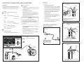
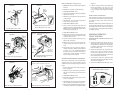
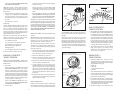
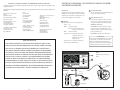
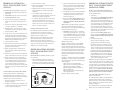
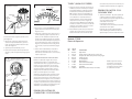
requerimiento para el buen funcionamiento y
facilidad de manejo del motor.
los procedimientos de prueba indicados en el
manual de servicio del motor requieren que el
motor funcione a una velocidad específica durante la prueba. Este instrumento proporciona
excelentes capacidades de monitoreo para este
propósito.
2. Ajustes de la inyección de combustible - Algunos sistemas de inyección de combustible
tienen un ajuste de autoridad mínimo y máximo
que se debe comprobar durante la puesta a
punto periódica o cuandoquiera que se encuentre algún problema con la velocidad en vacío.
CP7605
OPERATING INSTRUCTIONS
3. Pruebas misceláneas del motor - Muchos de
FULL ONE (1) YEAR WARRANTY
GARANTIA COMPLETA DE UN AÑO
Actron Manufacturing Company, 9999 Walford Avenue, Cleveland, Ohio 44102, warrants to the user
that this unit will be free from defects in materials
and workmanship for a period of one (1) year from
the date of original purchase. Any unit that fails within
this period will be repaired without charge when
returned to the Factory. Actron requests that a copy
of the original, dated sales receipt be returned with
the unit to determine if the warranty period is still
in effect. This warranty does not apply to damages
caused by accident, alterations, or improper or unreasonable use. Expendable items, such as batteries,
fuses, lamp bulbs, flash tubes also are excluded from
the scope of this warranty. ACTRON MANUFACTURING
COMPANY DISCLAIMS ANY LIABILITY FOR INCIDENTAL
OR CONSEQUENTIAL DAMAGES FOR BREACH OF ANY
WRITTEN WARRANTY ON THE UNIT. Some states do
not allow the disclaimer of liability for incidental or
consequential damages, so the above disclaimer
may not apply to you. This warranty gives specific
legal rights, and you may also have rights which vary
from state to state.
Actron Manufacturing Company, 9999 Walford Avenue,
Cleveland, Ohio 44102, EE.UU., garantiza al usuario que esta
unidad estará libre de defectos de materiales y mano de
obra por un (1) año a partir de la fecha de compra del comprador original. Cualquier unidad que falle dentro de este
período será reparada opción de Actron sin cargo cuando
se regrese a la fábrica. Actron requiere que un comprobante
de compra (recibo de venta) fechado acompañe la unidad
para determinar si está en garantía. Esta garantía no es
aplicable a daños causados por accidente, alteraciones,
usos impropios o no razonables. Artículos consumibles,
tales como baterías, fusibles, lámparas y tubos de destello
quedan excluidos de esta garantía. Actron Manufacturing
Company rechaza cualquier responsabilidad de daños
incidentales o indirectos por incumplimiento de cualquier
garantía escrita de la unidad. Algunos estados de los
EE.UU. y ciertos países no permiten el rechazo de cualquier
responsabilidad de daños incidentales o indirectos, por
lo que el rechazo anterior puede no ser aplicable en su
caso. Esta garantía concede derechos legales específicos
y es posible que Ud. tenga otros derechos que varían de
estado a estado de los EE.UU. y de país a país.
Dwell/Tach/Voltmeter
FOR 12 VOLT ELECTRONIC OR
CONVENTIONAL IGNITION SYSTEMS
• OPERATING INSTRUCTIONS
• SAFETY RULES
• TUNE-UP PROCEDURES
• REPAIR PARTS
Angulo de cierre/Tacómetro/Voltímetro
PARA SISTEMAS DE ENCENDIDO ELECTRONICO O CONVENCIONAL DE 12 VOLTIOS
©1996, Actron Manufacturing Company
Actron Manufacturing Co.
9999 Walford Avenue
Cleveland, Ohio 44102-4696
Sunpro is a registered trademark of Sun Electric Corporation and is
used under exclusive license.
2-219301
20
•
•
•
•
INSTRUCCIONES DE OPERACION
REGLAS DE SEGURIDAD
PROCEDIMIENTOS PARA LA PUESTA A PUNTO
PIEZAS DE REPUESTO
Instrucciones en español — página 11
SAFETY GUIDELINES
TO PREVENT ACCIDENTS THAT COULD RESULT IN SERIOUS INJURY AND/OR DAMAGE TO YOUR VEHICLE OR TEST EQUIPMENT, CAREFULLY FOLLOW THESE SAFETY
RULES AND TEST PROCEDURES
SAFETY EQUIPMENT
DRIVE position. Refer to your vehicle service manual
for more information.
Fire Extinguisher
Never work on your car without having a suitable
fire extinguisher handy. A 5-lb or larger CO2 or
dry chemical unit specified for gasoline/chemical/electrical fires is recommended.
Fireproof Container
Rags and flammable liquids should be stored only
in fireproof, closed metal containers. A gasolinesoaked rag should be allowed to dry thoroughly
outdoors before being discarded.
Safety Goggles
We recommend wearing safety goggles when
working on your car, to protect your eyes from
battery acid, gasoline, and dust and dirt flying off
moving engine parts.
HOT SURFACES
Avoid contact with hot surfaces such as exhaust
manifolds and pipes, mufflers (catalytic converters),
radiator and hoses. Never remove the radiator cap
while the engine is hot, as escaping coolant under
pressure may seriously burn you.
SMOKING AND OPEN FLAMES
Never smoke while working on your car. Gasoline
vapor is highly flammable, and the gas formed in
a charging battery is explosive.
BATTERY
Do not lay tools or equipment on the battery. Accidentally grounding the“HOT”battery terminal can
shock or burn you and damage wiring, the battery
or your tools and testers. Be careful of contact with
battery acid. It can burn holes in your clothing and
burn your skin or eyes.
When operating any test instrument from an
auxiliary battery, connect a jumper wire between
the negative terminal of the auxiliary battery and
ground on the vehicle under test. When working
in a garage or other enclosed area, auxiliary battery should be located at least 18 inches above
the floor to minimize the possibility of igniting
gasoline vapors
NOTE: Never look directly into the carburetor throat
while the engine is cranking or running, as sudden
backfire can cause burns.
LOOSE CLOTHING AND LONG HAIR
(MOVING PARTS)
Be very careful not to get your hands, hair or clothes
near any moving parts such as fan blades, belts
and pulleys or throttle and transmission linkages.
Never wear neckties or loose clothing when working on your car.
JEWELRY
Never wear wrist watches, rings or other jewelry
when working on your car. You’ll avoid the possibility of catching on moving parts or causing
an electrical short circuit which could shock or
burn you.
HIGH VOLTAGE
VEHICLE MANUAL, SOURCES FOR SERVICE INFORMATION
The following is a list of publishers who have service manuals for your specific vehicle at
nominal cost.
Write to them for availability and prices, specifying the make, style, and model year of your
vehicle.
American Motors Corporation
Myriad
8835 General Drive
Plymouth Township, MI 48170
Chrysler Corporation
Dyment Distribution Service
Service Publication
20770 Westwood Drive
Strongsville, OH 44136
Ford Publications Department
Helm Incorporated
Post Office Box 07150
Detroit, MI 48207
Buick
Tuar Company
Post Office Box 354
Flint, MI 48501
Oldsmobile
Lansing Lithographers
Post Office Box 23188
Lansing, MI 48909
Cadillac, Chevrolet, Pontiac
Helm Incorporated
Post Office Box 07130
Detroit, MI 48207
The carbon monoxide in exhaust gas is highly toxic.
To avoid asphyxiation, always operate vehicle in a
well-ventilated area. If vehicle is in an enclosed area,
exhaust should be routed directly to the outside
via leakproof exhaust hose.
The jack supplied with the vehicle should be used
only for changing wheels. Never crawl under car
or run engine while vehicle is on a jack.
Make sure that your car is in Park or Neutral, and
that the parking brake is firmly set.
NOTE: Some vehicles have an automatic release
on the parking brake when the gear shift lever
is removed from the PARK position. This feature
must be disabled when it is necessary (for testing)
to have the parking brake engaged when in the
2
Cordura Publications
Mitchell Manuals, Inc.
Post Office Box 26260
San Diego, CA. 92126
Motor’s Auto Repair Manual
Hearst Company
250 W. 55th Street
New York, NY 10019
THIS MANUAL PRESENTS COMPLETE HOOKUP INSTRUCTIONS FOR THE
DWELL/TACH/VOLTMETER, IT ALSO DESCRIBES MANY OF THE TESTS THAT THIS
INSTRUMENT IS CAPABLE OF PERFORMING AS WELL AS WHEN THEY SHOULD
BE USED BASED ON VEHICLE PERFORMANCE, TUNE-UP OR TROUBLE ENCOUNTERED. CONSULT YOUR VEHICLE SERVICE MANUAL FOR SPECIFIC TUNE-UP INFORMATION AND TEST PROCEDURES. ALWAYS FOLLOW THE MANUFACTURER’S
SPECIFICATIONS AND TEST PROCEDURES FOR ADJUSTING DWELL ANGLE AND
IDLE SPEED, ESPECIALLY ON VEHICLES WITH MODERN ELECTRONIC IGNITION
AND EMISSION CONTROLS. DO NOT ATTEMPT TO SERVICE A VEHICLE WITHOUT
THE MANUFACTURER’S INSTRUCTIONS AND SPECIFICATIONS.
JACK
SETTING THE BRAKE
Domestic and Import Cars
Chilton Book Company
Chilton Way
Radnor, PA 19089
IMPORTANT
High voltage — 30,000 to 50,000 volts — is present
in the ignition coil, distributor cap, ignition wires
and spark plugs. When handling ignition wires
while the engine is running, use insulated pliers to
avoid a shock. While not lethal, a shock may cause
you to jerk involuntarily and hurt yourself.
VENTILATION
OTHER SOURCES- Nonfactory
3
ACCESSORIES
FUNCTIONS, CONNECTIONS AND ACCESSORIES
Fig. 3
See Figure 2.
of the instrument.
DESCRIPTION
3. TEST LEAD
Hook this lead to the proper test point in the
vehicle to perform tests as required and as
described below:
The Model CP7605 Dwell/Tach/Voltmeter has a
clearly labeled function switch and meter as shown
in the Master Hookup diagram, Figure 1 below.
VOLTAGE MEASUREMENTS
1. METER
This meter displays the following scales:
• Volts
0-16
• RPM
0-2000 (8 cylinder)
GREEN CLIP – Connect to the Positive (+) voltage source to be measured. (+ Battery terminal,
alternator output terminal, lamp socket, etc.).
BLACK CLIP – Vehicle ground.
0-4000(4cylinder
– multiply
CAUTION!
8 cylinder scale
Avoid connecting the BLACK CLIP to the
negative(-) battery terminal or any fuel system components in the event that glasses are
present which could explode from sparking
connections.
by 2)
• RPM
0-2500 (6 cylinder)
• Dwell
0-45 degrees (8 cylinder)
0-90 degrees (4
cylinder–
multiply 8 cylinder by 2)
• Dwell
0-60 degrees (6 cylinder)
• Points
OK/Defective
DWELL/TACH/BREAKER POINT RESISTANCE
MEASUREMENT
GREEN CLIP – Connect to the Tach or negative
(-) ignition coil terminal. See Figures 3 through
10 for specific applications
2. FUNCTION SELECTOR
This selects the RPM, Dwell, or Volts functions
BLACK CLIP – Vehicle Ground. See CAUTION
under voltage measurements.
1. GM DIAGNOSTIC ADAPTOR
The GM Diagnostic Adaptor is used to make
connection to vehicle equipped with the GM Diagnostic Connector, (1976 –1982). It is also used
to make connection to Toyota vehicles which
use the IIA (Integrated Ignition Assembly). See
Figures 9 and 10 for adaptor application.
TO BALLAST
GREEN
CLIP
(BAT.)
CONTROL
UNIT
2. GM HEI ADAPTOR
The GM HEI Adaptor is used to provide connection to the “TACH” terminal on GM HEI systems.
See Figure 7 for typical installation.
TO CONTROL
UNIT
COIL
3. FORD COIL CLIP
The Ford Coil Clip is used for ignition systems
which have booted ignition coil connections.
See Figure 4 for clip application.
All Chrysler Corporation Electronic Ignitions, 6 & 8 cylinder shown
1972 - 1986
Fig. 4
ELECTRICAL SYSTEM TESTS –
"VOLTS" POSITION
Fig. 2
Primary Tach/Dwell Connection –
GREEN Clip
TO IGNITION
SWITCH
Accessories
3
TO DIST.
FORD
ADAPTER
GREEN
CLIP
1
Fig. 1
Master Hookup Diagram
Primary Tach Connection —
GREEN Clip
2
1974 Ford Electronic and All Breaker
Points Ignition Systems
Fig. 5
BLACK
Primary Tach Connection —
GREEN Clip
GREEN
CLIP
ENGINE
GROUND
DIST. OR
TACH
GREEN
BAT.
DISTRIBUTOR
Ford Solid State & Dura Spark systems
1975 - 1986
COIL
4
5
Fig. 6
Fig. 9
Primary Tach Connection —
GREEN Clip
Primary Tach Connection —
GREEN Clip
diagnosis.
1. GREEN CLIP – Connect to the Positive (+) Battery
terminal.
7. If battery voltage remains abnormally high
(above approximately 10.5 volts) on a slow
or no cranking engine, the problem may be
loose or corroded connection(s) in the cranking
circuit.
2. BLACK CLIP – Connect to Vehicle Ground.
SPADE
TERMINAL
ADAPTER
GREEN
CLIP
GREEN
CLIP
BASIC SYSTEM CHECK – Charging Voltage
3. FUNCTION SELECTOR – Volts
4. Start engine and allow it to warm up completely.
Operate it at curb idle.
MISCELLANEOUS VOLTAGE TESTS
5. With all accessories off observe the 16 volt scale
on the analyzer.
This instrument can perform many of the voltage
tests called out in the vehicle service manual, such
as voltages at lamp sockets, motors, solenoids
and relays.
6. Normal Result – 13.2 to 15.2 volts or as specified
in the vehicle service manual.
7. FUNCTION SELECTOR – RPM
GM Diagnostic Connector and
Delco HEI Systems 1976 - 1982
Ford TFI Systems 1981 - 1986
Fig. 7
Fig. 10
Primary Tach Connection —
GREEN Clip
Primary Tach Connection —
GREEN Clip
TO
IGNITION
SWITCH
INSERT
DIAGNOSTIC
ADAPTER
GREEN
CLIP
REMOVE CAP
FROM TACH
TEST CONNECTOR
GREEN
CLIP
ADAPTER
Toyota IIA (Integrated Ignition Assembly) 1983 - 1986
Delco HEI 1974 - 1986 Integral Coil
NOTE: The voltmeter function of this instrument can
be used anywhere the vehicle service manual calls
for voltage measurement except in those applications which call for 10 Megohm input impedance
or a digital voltmeter.
8. Select a step on the fast idle cam which will
maintain engine speed between l800 and 2000
RPM (or have an assistant hold engine speed
in this range) through Step 12.
9. FUNCTION SELECTOR – Volts
10. Observe the 16 volt scale on the analyzer. The
voltage should not have changed from Step 6
more than about .5 volts.
IGNITION SYSTEM TEST –
"VOLTS" POSITION
11. Load the electrical system by turning on the
lights, Hi fan, and wipers.
BREAKER POINT RESISTANCE TEST (Breaker Point
Systems Only)
12. Observe the 16 volt scale on the analyzer. The
voltage should not drop below about 13.0
volts.
1. Visually check the breaker points and associated wiring and connections. Check to see that
the lead from the distributor to the Negative
(-) terminal of the ignition coil is not damaged
(nicked insulation, etc.)
13. Shut off all accessories, return the engine to
curb idle, and shut it off. If the results obtained
in Step 6, 10 or 12 are significantly different
from those shown or from the vehicle service
manual values, further diagnosis is required:
see your vehicle service manual.
2. Remove the distributor cap and inspect the
breaker points. Properly adjusted breaker
points become light gray in color in normal
use. If they are blued, blackened or pitted, they
have exceeded their normal life.
3. To prevent the engine from starting, disable
the ignition system by grounding the coil tower
wire as shown in Figure 12.
CRANKING VOLTAGE AND BATTERY CONDITION
Fig. 8
Fig. 11
Primary Tach Connection —
GREEN Clip
Performance Check ONLY
Note: This is NOT a Tach Connection point.
DWELL CONNECTOR (GREEN)
If the engine cranks slowly or not at all, the battery,
cranking motor, and associated wiring may be
at fault. Check the cranking voltage as indicated
below.
4. Connect the GREEN and BLACK clips as de-
1. Connect the analyzer to the vehicle battery as
shown in Figure 1.
Fig. 12
Breaker Point Ignition System
2. Disable the engine from starting as shown in
Figure 12 or as explained in your vehicle service
manual
GREEN
CLIP
Disabling Procedure
3. FUNCTION SELECTOR – Volts
GREEN CLIP or
Ground Jumper
– See Vehicle
Service Manual
Delco HEI 1974 - 1986 External Coil
GM C3 (Computer Command Control)
6
4. Crank the engine while observing the 16 volt
scale on the analyzer.
5. Normal Result – 9.6 volts or more at 70°F. Voltage
will drop slightly as temperature decreases.
6. If the results are significantly out of specification
consult your vehicle service manual for further
ENGINE GROUND
7
scribed under DWELL/TACH/BREAKER POINT
RESISTANCE MEASUREMENTS
Start the engine and allow it to warm up (upper
radiator hose hot.)
NOTE: When testing a vehicle with dual points,
alternately block one set of points open with a
piece of insulating material while the other set is
being tested.
Operate the engine at curb idle OR the RPM
specified by the vehicle emission control label
or the vehicle service manual for measuring
dwell.
5. Turn the ignition key ON. If the meter reads
voltage, (12.5 - 13.0) the points are OPEN. Crank
the engine a fraction of a revolution at a time
until the meter reads in the left hand area of
the scale.
Check the RPM by switching the FUNCTION
SELECTOR TO RPM and reading the appropriate
meter scale. Return the FUNCTION SELECTOR to
DWELL and observe the correct dwell scale
Fig. 13
Test Results:
Normal – Meter reads in the OK zone of the Points
scale. The Analyzer may indicate high point resistance on a new set of points until they have been
run in the vehicle for a few miles and have been
properly seated. This condition may be ignored as
long as any defects discovered during the previous
visual check have been corrected.
DWELL ADJUSTMENT – Conventional Breaker Point
Systems
Abnormal – If the meter indicates in the Bad zone
when the points are closed, the points may be
defective or the following faults may exist:
On GM distributors with a small metal slide cover,
lift the cover and insert a l/8" Allen wrench in the
adjusting screw socket and adjust the dwell by
turning the wrench, as shown in Figure 13.
Poor distributor ground
Poor connection on the primary lead from
the distributor to the ignition coil
Defective distributor pigtail lead
Misaligned points
Poor points/plate ground inside distributor
On Ford, Chrysler, American Motors, and other
distributors not equipped with a small metal access slide cover, perform the following steps while
referring to Figure 14.
MORE THAN 3 DEGREES
1/8" ALLEN
WRENCH
ADJUSTMENT
SCREW
FUEL SYSTEM TESTS –
"DWELL" POSITION
1. General Motors C-3 (Computer Command Control) Mixture Control Solenoid Dwell (Carburetor equipped vehicles only). The GMC-3 system
controls Air/Fuel ratio with a mixture control
solenoid mounted in the carburetor. The basic
system performance check of this system calls
for the checking of the duty cycle or dwell of
the M/C solenoid. Note that regardless of the
number of cylinders in the vehicle, the reading
is always taken from the 6 cylinder scale.
checking DWELL angle. Usually, the vacuum hose
must be disconnected from the distributor and
plugged
Increase the engine speed from idle to about
1500 RPM and note the dwell angle (Figure 15).
Return the engine speed to idle and again note
the dwell angle. If the difference between the two
dwell angle readings is more than 3 degrees, check
for excessive wear in the breaker point plate and
couplings or excessive wear in the distributor shaft
gear and bushings.
Fig. 14
IGNITION SYSTEM TEST –
"DWELL" POSITION
2. Remove the distributor cap and rotor.
(All, except Delco-Remy Sliding Window Distributors)
DWELL TEST AND ADJUSTMENT – Breaker Point
Systems Only or Transistorized Systems which Use
Breaker Points.
4. With ignition switch ON and engine cranking
observe reading on the Dwell scale.
2. This analyzer may be used to check C-3 Dwell
(duty cycle). Refer to your vehicle service
manual for hookup instructions and performance results. See Figure 11.
Dwell Adjustment
ENGINE TESTS –
"RPM" POSITION
3. Connect a remote starter switch to the vehicle
or have an assistant crank the engine for you.
5. To adjust Dwell, loosen the locking screw
slightly and adjust the point gap with a feeler
gauge according to the procedure outlined in
the vehicle service manual. After adjustment,
tighten locking screw, and recheck dwell while
cranking engine. Repeat procedure if necessary.
(Figure 14.)
1. Preparation:
Before performing the DWELL TEST AND
ADJUSTMENT PROCEDURE, read the vehicle
emission control label or the vehicle service
manual to determine what should be done with
the vacuum hoses connected to the distributor
and the various advance/retard solenoids. Most
often, the vacuum hose must be disconnected
from the distributor and the end plugged with
a plastic golf “tee” or other plug.
6. Reassemble distributor and recheck dwell reading with engine operating at idle speed. Repeat
steps 5 and 6 if necessary.
Connect the GREEN and BLACK clips as described under TACH/DWELL/BREAKER POINT
RESISTANCE MEASUREMENTS.
ADJUSTMENT
SLOTTED HOLE
LOCKING SCREW
BREAKER
POINTS
1. Carburetor Adjustments – There are several
adjustments which should be checked as part
of a performance tune-up. Those which require
engine RPM monitoring are:
a. Curb idle
b. Base idle
c. Solenoid Controlled idle
d. Fast idle
BREAKER
POINTS
Your vehicle will likely have some combination
of these adjustments. Proper adjustment of
these settings is a requirement for good engine
performance and driveability.
ADJUSTMENT
SCREW
2. Fuel Injection Adjustments – Some fuel injection systems have a minimum and maximum
authority adjustment which should be checked
during routine performance tune-up or whenever idle problems are encountered.
DWELL VARIATION TEST
Read the owner’s manual or engine compartment
decal and follow the instructions regarding vacuum
line or advance-retard solenoid connections when
2. Test Procedure:
8
SECOND
READING
WINDOW
1. Remove coil wire from center tower of distributor
cap and ground the wire by connecting the loose
end to the engine or frame, See Figure 12.
Correct the defect and repeat the test.
Dwell Variation
FIRST
READING
NOTE: There is a direct relationship between dwell
and timing. However, it is only a one way relationship.
If you change the dwell angle of the breaker points,
you will automatically change the ignition timing.
Changing the timing, though, has no effect on the
dwell angle. FOR THIS REASON, IT IS IMPORTANT
TO RE-CHECK THE TIMING WHEN EVER THE DWELL
ANGLE HAS BEEN ADJUSTED.
The points are now closed.
Fig. 15
Typical General Motors
Breaker Points Distributor
3. Miscellaneous Engine Test – Many of the test
9
procedures in your vehicle service manual
require the engine to run at a specific RPM during the test. Your instrument provides excellent
monitoring capabilities for this purpose.
REGLAS DE SEGURIDAD
PARA IMPEDIR ACCIDENTES QUE PUEDAN CAUSAR GRAVES LESIONES Y/O
DAÑAR EL VEHICULO O EL EQUIPO DE PRUEBA, SEGUIR ATENTAMENTE ESTAS REGLAS DE
SEGURIDAD Y LOS PROCEDIMIENTOS DE PRUEBA.
Model CP7605
Replacement Parts
Key
No.
Part
No.
1
2
3
4
5
6
7
8
9
—
400-857
270-117
38-726
450-133
180-300
38-1342
1-1086
1-1085
400-855
2-219301
se saca la palanca de cambio de la posición PARK.
Se deberá inhabilitar esta características cuando sea
necesario (para pruebas) con el fin de tener el freno
de estacionamiento aplicado cuando la palanca esté
en DRIVE. Para más información al respecto, consultar
el manual de servicio del vehículo.
EQUIPO DE SEGURIDAD
Extinguidor de incendios
Description
Case, bottom
Screw, Case self-tap. #6-20 x 1"
Cable Assembly, Green and Black Clip
Cap, Glamour
Ford Adapter
GM Adapter
Switch Decal
Meter Decal
Window
Instruction Manual (Not shown)
NOTE: The circuit board and meter are not replacement parts
since the replacement of either requires recalibration of the instrument.
Nunca trabajar en un automóvil sin tener a mano un
extinguidor de incendios. Se recomienda un aparato
de CO2 ó agente químico seco de 5 lbs o más grande
especificado para incendios de gasolina/químicos/
eléctricos.
SUPERFICIES CALIENTES
Evitar el contacto con las superficies calientes como
múltiples y tubo de escape, silenciadores (catalíticos), radiador y mangueras. Nunca quitar la tapa
del radiador mientras el motor esté caliente, pues el
escape de refrigerante a presión puede causar graves
quemaduras.
Envase ignífugo
Los trapos y líquidos inflamables deben guardarse
solamente en envases metálicos cerrados e ignífugos.
Los trapos empapados en gasolina deben dejarse
secar al aire libre antes de botarlos.
Gafas protectoras
CIGARRILLOS Y LLAMAS EXPUESTAS
Recomendamos usar gafas cuando se trabaje en el
automóvil para protegerse los ojos contra el ácido de
la batería, la gasolina y el polvo y suciedad desprendidos de las piezas en movimiento del motor.
Nunca fumar mientras se trabaje en el automóvil. El
vapor de gasolina es muy inflamable, y el gas emitido
por una batería en carga es explosivo.
BATERIA
NOTA: Nunca mirar directamente al interior del
cuello del carburador mientras el motor está girando
o funcionando, pues el petardeo puede causar
quemaduras.
No apoyar las herramientas o el equipo encima de
la batería. La conexión a tierra imprevista del borne
“HOT” (VIVO) de la batería puede electrocutar o quemar y dañar los cables, la batería o las herramientas y
probadores. Tener cuidado de no tocar el ácido de la
batería. Puede quemar y agujerear la ropa y quemar
la piel o los ojos.
ROPA SUELTA Y CABELLO LARGO (PIEZAS MOVILES)
Tener cuidado de no tener las manos, cabello o
ropa cerca de las piezas móviles como las aspas del
ventilador, correas y poleas o varillaje del acelerador y
transmisión. Nunca usar corbata o ropa suelta cuando
se trabaje en el automóvil.
Cuando se haga funcionar un instrumento de prueba
desde una batería auxiliar, conectar un cable puente
entre el borne negativo de la batería auxiliar y tierra
en el vehículo que se esté probando. Cuando se esté
trabajando en un garage u otro ugar bajo techo,
situar la batería auxiliar a por lo menos 18 pulgadas
del suelo para reducir al mínimo la posibilidad de
inflamar los vapores de gasolina.
JOYAS
Nunca usar reloj pulsera, anillos u otras joyas cuando
se trabaje en el automóvil. Se evitará la posibilidad
de engancharse en las piezas móviles o causar un
cortocircuito que podría electrocutar o quemar.
ALTO VOLTAJE
VENTILACION
Hay alto voltaje—30.000 a 50.000 voltios— en la
bobina de encendido, tapa del distribuidor, cables del
encendido y bujías. Para mover los cables del encendido mientras el motor está funcionando, hacerlo con
alicates aislados para evitar electrochoque. Aunque
no es mortal, un electrochoque puede causar una
sacudida involuntaria y lastimadura.
El monóxido de carbono en los gases de escape es
sumamente tóxico. Para evitar asfixia, siempre hacer
funcionar el vehículo en un lugar bien ventilado. Si
el vehículo está en un lugar encerrado, instalar una
manguera a prueba de fugas en el tubo de escape
para expulsar los gases al exterior.
FRENO
GATO
Asegurar que el vehículo esté en PARK o punto muerto y que el freno de estacionamiento esté aplicado.
El gato que se suministra con el vehículo debe usarse
solamente para cambiar las ruedas. Nunca meterse
debajo de un automóvil o motor funcionando mientras el vehículo esté apoyado en el gato.
NOTA: Algunos vehículos tienen desconexión
automática en el freno de estacionamiento cuando
10
11
MANUAL DEL VEHICULO, FUENTES DE INFORMACION ACERCA DE SERVICIO.
La siguiente es una lista de editores que publican manuales de servicio para vehículos específicos a por
un precio nominal.
Escribirles para averiguar la disponibilidad y precios, especificando la marca, estilo y año del modelo del
vehículo.
American Motors Corporation
Myriad
8835 General Drive
Plymouth Township, MI 48170
Chrysler Corporation
Dyment Distribution Service
Service Publication
20770 Westwood Drive
Strongsville, OH 44136
Ford Publications Department
Helm Incorporated
Post Office Box 07150
Detroit, MI 48207
Buick
Tuar Company
Post Office Box 354
Flint, MI 48501
Oldsmobile
Lansing Lithographers
Post Office Box 23188
Lansing, MI 48909
Cadillac, Chevrolet, Pontiac
Helm Incorporated
Post Office Box 07130
Detroit, MI 48207
OTRAS FUENTES-Privadas
Automóviles norteamericanos y
extranjeros
Chilton Book Company
Chilton Way
Radnor, PA 19089
Cordura Publications
Mitchell Manuals, Inc.
Post Office Box 26260
San Diego, CA. 92126
Motor’s Auto Repair Manual
Hearst Company
250 W. 55th Street
New York, NY 10019
CONTROLES, CONEXIONES Y ACCESORIOS DEL ANGULO DE CIERRE/
TACOMETRO/VOLTIMETRO
2 SELECTOR DE FUNCION
DESCRIPCION
Este selecciona las funciones de RPM, ángulo de
cierre o voltios del instrumento.
El ángulo de cierre/tacómetro/voltímetro modelo
CP7605 tiene un interruptor y medidor claramente
rotulados como se muestra en el diagrama de conexiones principal, figura 1 a continuación.
3 CONDUCTOR DE PRUEBA
Conectar este conductor al punto de prueba
correcto en el vehículo para efectuar las pruebas según se requiera y describen más abajo.
1 MEDIDOR
Este medidor indica las escalas siguientes:
• Voltios
0-16
MEDICIONES DE VOLTAJE
• RPM
0-2000 (8 cilindros)
0-4000 (4 cilindros - multiplicar la
escala de 8 cilindros por 2)
• RPM
0-2500 (6 cilindros)
PINZA VERDE - Conectar la fuente de voltaje
positivo (+) que se va a medir. (Borne + de la
batería, terminal de salida del alternador, receptáculo de bombilla, etc.).
PINZA NEGRA - Puesta a tierra del vehículo.
• Angulo de cierre 0-45 grados (8 cilindros)
0-90 grados (4 cilindros multiplicar la escala de 8
cilindros por 2)
IMPORTANTE
ESTE MANUAL PRESENTA LAS INSTRUCCIONES COMPLETAS PARA LA CONEXION DEL ANALIZADOR DE VIBRACIONES DEL MOTOR. ADEMAS DESCRIBE
MUCHAS DE LAS PRUEBAS QUE ESTE INSTRUMENTO ES CAPAZ DE REALIZAR COMO ASIMISMO CUANDO SE DEBEN USAR EN BASE AL RENDIMIENTO
DEL VEHICULO, PUESTA A PUNTO DEL MOTOR O PROBLEMA ENCONTRADO.
CONSULTAR EL MANUAL DE SERVICIO DEL VEHICULO PARA LA INFORMACION
ESPECIFICA DE LA PUESTA A PUNTO Y LOS PROCEDIMIENTOS DE PRUEBA.
SEGUIR LAS ESPECIFICACIONES DEL FABRICANTE Y LOS PROCEDIMIENTOS
DE PRUEBA PARA AJUSTAR EL ANGULO DE CIERRE Y LA VELOCIDAD EN VACIO
(RALENTI), ESPECIALMENTE EN VEHICULOS CON ENCENDIDO ELECTRONICO Y
CONTROLES DE EMISION MODERNOS. NO TRATAR DE REPARAR UN VEHICULO
SIN TENER LAS INSTRUCCIONES Y ESPECIFICACIONES DEL FABRICANTE.
¡PRECAUCION!
Evitar conectar la PINZA NEGRA al borne negativo
(-) de la batería o a cualquier componente del
sistema de combustible, ya que si llegaran a
haber gases presenten podrían explotar debido a
las chispas producidas al hacer las conexiones.
• Angulo de cierre 0-60 grados (6 cilindros)
• Platinos Correctos/Defectuosos
Fig. 1
Diagrama de conexiones principales
NEGRO
TIERRA DEL
MOTOR
DISTRIBUIDOR O
TACOMETRO
VERDE
BAT.
DISTRIBUIDOR
BOBINA
12
13
MEDICION DE LA RESISTENCIA DEL ANGULO DE
CIERRE/TACOMETRO/PLATINOS
Fig. 3
PINZA VERDE - Conectar al tacómetro o terminal
negativo (-) de la bobina de encendido. Ver las figuras 3 a la 10 para las aplicaciones específicas.
Fig. 9
CONEXION PRINCIPAL DEL
TACOMETRO - Pinza VERDE
CONEXION PRINCIPAL DEL
TACOMETRO - Pinza VERDE
AL EQUILIBRADOR
PINZA
VERDE
PINZA NEGRA - Puesta a tierra del vehículo. Ver
PRECAUCION en las mediciones de voltaje.
Fig. 6
CONEXION PRINCIPAL DEL
TACOMETRO - Pinza VERDE
UNIDAD DE
CONTROL
(BAT.)
ADAPTADOR DE TERMINAL DE HORQUILLA
PINZA
VERDE
PINZA
VERDE
ADAPTADOR
ACCESORIOS
Ver la figura 2.
1. ADAPTADOR DE DIAGNOSTICO GM
El adaptador de diagnóstico se usa para conectarse a los vehículos dotados del conector de
diagnóstico GM (1976-1982). Además se usa
para conectarse a los vehículos Toyota que usan
el conjunto de encendido integrado (IIA). Ver las
figuras 9 y 10 para la instalación.
A LA UNIDAD
DE CONTROL
BOBINA
Todos los encendidos electrónicos de Chrysler Corporation, se muestran 6 y 8 cilindros
1972 - 1985
2. ADAPTADOR HEI GM
El adaptador HEI GM se usa para proveer conexión al terminal “TACH” en los sistemas HEI GM.
Ver la figura 7 para la instalación típica.
Fig. 4
Fig. 7 CONEXION PRINCIPAL DEL
TACOMETRO - Pinza VERDE
CONEXION PRINCIPAL DEL
TACOMETRO/ANGULO DE
CIERRE - Pinza VERDE
AL INTERRUPTOR DE
ENCENDIDO
3. CHAVETA DE LA BOBINA FORD
La chaveta de la bobina Ford se usa para los
sistemas de encendido que tienen conexiones
de la bobina de encendido con manguito aislador. Ver la figura 4 para la instalación.
Conector de diagnóstico GM y
sistemas HEI Delco 1976 - 1982
Sistemas TFI Ford 1981 - 1985
Fig. 10
AL DISTRIBUIDOR
ADAPTADOR
FORD
PINZA
VERDE
ADAPTADOR
INCLUIDO
INSERTAR EL
ADAPTADOR DE
DIAGNOSTICO
PINZA
VERDE
Fig. 2
QUITAR LA TAPA
DEL CONECTOR
DE PRUEBA DEL
TACOMETRO
PINZA
VERDE
AL INTERRUPTOR DE
ENCENDIDO
ADAPTADOR
INCLUIDO
Accesorios
CONEXION PRINCIPAL DEL
TACOMETRO - Pinza VERDE
ADAPTADOR
Sistema de encendido electrónico Ford y
todos los sistemas con platinos
Conjunto de encendido integrado (IIA)
Toyota 1983-1985
HEI Delco 1974 - 1985
1
Fig. 5
Fig. 8
CONEXION PRINCIPAL DEL
TACOMETRO - Pinza VERDE
Fig. 11
CONEXION PRINCIPAL DEL
TACOMETRO - Pinza VERDE
Verificación de rendimiento
SOLAMENTE
Nota: Este NO es un punto de conexión del tacométro.
3
PINZA
VERDE
2
PINZA
VERDE
PINZA VERDE
o cable puente
a tierra - Ver el
manual de servicio
del vehículo
Sistemas de estado sólido y Dura Spark
Ford 1975 - 1985
14
CONECTOR DEL ANGULO DE
CIERRE (VERDE)
GM C3 (Control de comando por computadora)
HEI Delco 1974 - 1985 Bobina externa
15
3. Selector de función - Voltios
PRUEBAS DEL SISTEMA ELECTRICO - POSICION PARA "VOLTS"
(VOLTIOS)
4. Girar el motor mientras se observa la escala de 16
voltios en el analizador.
5. Resultado normal - 9.6 voltios o más a 70°F. El
voltaje bajará un poco cuando la temperatura
disminuye.
COMPROBACION BASICA DEL SISTEMA - Voltaje de carga
1. PINZA VERDE - Conectarla al borne positivo (+)
de la batería.
6. Si los resultados están muy desviados de la
especificación, consultar el manual de servicio del
vehículo para continuar el diagnóstico.
2. PINZA NEGRA - Conectar a tierra en el vehículo.
3. SELECTOR DE FUNCION - Voltios
7. Si el voltaje de la batería permanece anormalmente
alto (sobre aproximadamente 10.5 voltios) en un
motor que arranca lento o no arranca, el problema
puede ser una conexión o conexiones sueltas o corroídas en el circuito de arranque.
4. Arrancar el motor y dejar que se caliente totalmente. Hacerlo funcionar a velocidad en vacío
lenta.
5. Con todos los accesorios desactivados observar
la escala de 16 voltios en el analizador.
6. Resultado normal - 13.2 a 15.2 voltios o según lo
especificado en el manual de servicio del vehículo.
PRUEBAS MISCELÁNEAS DE VOLTAJE
Este instrumento puede realizar muchas de las pruebas
de voltaje indicadas en el manual de servicio del
vehículo, tales como el voltaje en los receptáculos de
bombillas, motores, solenoides y relés.
7. Selector de función - RPM
8. Escoger un paso en la leva de velocidad en vacío
rápida que mantenga la velocidad del motor
entre 1800 y 2800 rpm, o pedir que un ayudante
mantenga la velocidad del motor en esta gama.
Mantener esta velocidad hasta el paso 12.
NOTA: Las funciones del voltímetro de este instrumento se pueden usar en cualquier parte que el
manual de servicio del vehículo lo indique para
medir el voltaje excepto en aquellas aplicaciones que
exigen el uso de una impedancia de entrada de 10
megaohmios o un voltímetro digital.
9. Selector de función - Voltios
10. Observar la escala de 16 voltios en el analizador.
El voltaje no debiera haber cambiado desde el
paso 5 más de unos 0.5 voltios.
11. Cargar el sistema eléctrico encendiendo las
luces, el ventilador a alta velocidad y los limpiaparabrisas.
PRUEBA DEL SISTEMA DE ENCENDIDO - POSICION PARA "VOLTS"
(VOLTIOS)
12. Observar la escala de 16 voltios en el analizador. El
voltaje no debe bajar a menos de unos 13.0 voltios.
RESISTENCIA DE LOS PLATINOS (sistemas con platinos solamente).
13. Apagar todos los accesorios, volver a dejar el
motor a velocidad en vacío y después apagarlo.
Si los resultados obtenidos en los pasos 6, 10 ó
12 son muy diferentes de aquéllos mostrados
o de los valores indicados en el manual de
servicio del vehículo, pueden ser necesarios más
diagnósticos; consultar el manual de servicio del
vehículo.
1. Revisar visualmente el platino y la cablería y
conexiones asociadas. Ver que el conductor del
distribuidor al terminal negativo (-) de la bobina
de encendido no esté dañado (aislante mellado,
etc.).
Fig. 12
Procedimiento de inhabilitación
Sistema de encendido con platinos
VOLTAJE DE ARRANQUE Y CONDICION DE LA BATERIA
Si el motor gira lentamente o simplemente no
gira, la falla puede estar en la batería, el motor de
arranque y la cablería respectiva. Probar el voltaje de
arranque como se indica a continuación.
2. Quitar la tapa del distribuidor e inspeccionar los
platinos. Los platinos bien ajustados adquieren
un color gris claro con el uso normal. Si están
azulados, ennegrecidos o picados, ya han excedido su vida útil normal.
PRUEBA DEL SISTEMA DE ENCENDIDO - POSICION PARA "DWELL"
(ANGULO DE CIERRE)
PRUEBA Y AJUSTE DEL ÁNGULO DE CIERRE (Sistemas con platinos solamente o sistemas transistorizados que utilizan platinos).
3. Para impedir que el motor arranque, inhabilitar
el sistema de encendido conectando a tierra
el alambre de la torre de la bobina, como se
muestra en la figura 12.
1. Preparación:
Antes de efectuar el PROCEDIMIENTO DE PRUEBA
Y AJUSTE DEL ANGULO DE CIERRE, leer la etiqueta de control de emisiones del vehículo o el
manual de servicio del vehículo para determinar
lo que se debe hacer con las mangueras de vacío
conectadas al distribuidor y los distintos solenoides de avance/retardo. En la mayoría de los
casos, la manguera de vacío debe desconectarse
del distribuidor y el extremo taparse con un “tee”
de plástico de golf u otro tapón.
4. Conectar las pinzas VERDE y NEGRA tal como se
describe en la sección MEDICION DE LA RESISTENCIA DEL ANGULO DE CIERRE/TACOMETRO/
VOLTIMETRO.
NOTA: Cuando se pruebe un vehículo con platinos
dobles, bloquear alternadamente un juego de
platinos abierto con un pedazo de material aislante
mientras se prueba el otro juego.
5. CONECTAR la llave de contacto. Si el medidor
indica voltaje de la batería (12.5 - 13.0) los platinos están ABIERTOS. Girar el motor una fracción
de una revolución a la vez hasta que el medidor
indique en el lado izquierdo de la escala.
Conectar las pinzas VERDE y NEGRA según lo
descrito en la sección MEDICION DE LA RESISTENCIA DEL TACOMETRO/ANGULO DE CIERRE/VOLTIMETRO.
2. Procedimiento de prueba:
Los platinos ahora están cerrados.
Arrancar el motor y dejar que se caliente
(manguera superior del radiador caliente).
Resultados de la prueba:
Normal – El medidor indica en la zona OK (CORRECTO) de la escala para platinos. El analizador
puede indicar una resistencia alta de los platinos
cuando el juego de platinos es nuevo hasta que han
funcionado en el vehículo por unos pocos kilómetros y están bien asentados. Esta condición puede
pasarse por alto siempre que se haya corregido
cualquier defecto descubierto durante la revisión
visual previa.
Hacer funcionar el motor a velocidad en vacío
lenta O a las revoluciones por minuto especificadas en la etiqueta de control de emisiones del
vehículo o en el manual de servicio del vehículo
para medir el ángulo de cierre. Comprobar las
RPM cambiando el SELECTOR DE FUNCION a la
posición RPM correcta y leer en la escala apropiada del medidor. Volver a poner el SELECTOR
DE FUNCION en Angulo de cierre y observar la
escala correcta para ángulo de cierre.
Anormal – Si el medidor indica en la zona BAD (DEFICIENTE) de la escala para platinos puede indicar
platinos defectuosos o que existe cualquiera de las
averías siguientes:
NOTA: Existe una relación directa entre el ángulo de
cierre y el reglaje del encendido. Sin embargo, es una
relación en un solo sentido. Si se cambia el ángulo de
cierre de los platinos, se cambiará automáticamente
el reglaje del encendido. No obstante, cambiar el reglaje del encendido no tiene ningún efecto sobre el
ángulo de cierre. POR ESTA RAZON, ES IMPORTANTE
VOLVER A COMPROBAR EL REGLAJE DEL ENCENDIDO
CADA VEZ QUE SE AJUSTA EL ANGULO DE CIERRE.
Mala conexión a tierra del distribuidor
Mala conexión en el conductor primario del
distribuidor a la bobina de encendido
Cable de llegada al distribuidor defectuoso
Platinos desalineados
Mala conexión a tierra de los platinos/placa
dentro del distribuidor
Corregir el defecto y repetir la prueba.
AJUSTE DEL ANGULO DE CIERRE - Sistemas con
platinos convencionales
En los distribuidores de GM con una tapa deslizante
metálica pequeña, levantar la tapa e insertar una
llave allen de 1/8” en el hueco del tornillo de ajuste y
ajustar el ángulo de cierre girando la llave, como se
muestra en la figura 13.
1. Conectar el analizador al vehículo como se
muestra en la figura 1.
2. Inhabilitar el motor para que no arranque, como
se explica en el manual de servicio del vehículo
o como se muestra en la figura 12.
TIERRA DEL MOTOR
16
En los distribuidores de la Ford, Chrysler, American
Motors y otros sin la tapita metálica deslizante,
17
Fig. 13
Fig. 15 Variacion del ángulo de cierre
DISTRIBUIDOR CON PLATINOS
TIPICO GENERAL MOTORS
MAS DE 3 GRADOS
PRIMERA
LECTURA
SEGUNDA
LECTURA
VENTANILLA
LLAVE
ALLEN DE
1/8”
TORNILLO DE
AJUSTE
4. Con la llave de contacto CONECTADA y el motor
girando observar la indicación en la escala para
ángulo de cierre.
5. Para ajustar el ángulo de cierre, soltar un poco el
tornillo de fijación y ajustar la separación de los
platinos con un calibrador de separaciones de
acuerdo al procedimiento descrito en el manual
de servicio del vehículo. Después del ajuste, apretar el tornillo de fijación y volver a comprobar el
ángulo de cierre mientras el motor está girando.
Si es necesario, repetir el procedimiento. (Figura
14).
proceder de la manera siguiente, teniendo como
guía la figura 14.
1. Desconectar el cable de la bobina de la torre
central en la tapa del distribuidor y ponerlo a
tierra conectando el extremo suelto al motor o
chasis. Ver la figura 12.
2. Quitar la tapa del distribuidor y el rotor.
6. Volver a armar el distribuidor y comprobar la
indicación del ángulo de cierre con el motor
funcionando a velocidad en vacío. Si es necesario,
repetir los pasos 5 y 6.
3. Conectar un interruptor de arranque remoto al
vehículo o pedir a un ayudante que haga girar el
motor.
Fig. 14
PRUEBA DE VARIACION DEL ANGULO DE CIERRE
Ajuste del ángulo de cierre
(Todos los distribuidores excepto los con tapita deslizante
Delco-Remy)
Cuando se compruebe el ángulo de cierre, leer
el manual del propietario o la calcomanía en el
compartimento del motor y seguir las instrucciones
respecto a lo que se debe hacer con las conexiones de las mangueras de vacío y de los solenoides
de avance/retardo. En la mayoría de los casos, la
manguera de vacío debe desconectarse del distribuidor y el extremo taparse con un tapón.
AGUJERO RANURADO PARA
AJUSTE
Aumentar la velocidad del motor desde vacío lento
hasta aproximadamente 1500 rpm y anotar el ángulo de cierre. Volver el motor a velocidad en vacío y
nuevamente anotar el ángulo de cierre. Si la diferencia entre las dos indicaciones es más de 3 grados, ver
si la placa y acoplamientos de los platinos están muy
desgastados o si los bujes y el engranaje del eje del
distribuidor están demasiado desgastados.
TORNILLO DE
FIJACIÓN
PLATINOS
TORNILLO DE
AJUSTE
PLATINOS
las instrucciones para hacer las conexiones y los
resultados del funcionamiento. Ver la figura 11.
"DWELL" (ANGULO DE CIERRE)
1. Angulo de cierre del solenoide de control de la
mezcla C-3 (control de comando por computadora) de General Motors - (Vehículos dotados
de carburador solamente). El sistema C-3 de
GM controla la relación aire/combustible con
un solenoide de control de la mezcla ubicado
en el carburador. La comprobación básica
del funcionamiento de este sistema requiere
comprobar el ciclo de servicio o “ángulo de
cierre” del solenoide M/C. Notar que indiferente
al número de cilindros en el motor, la lectura del
“ángulo de cierre” siempre se hace en la escala
para ángulo de cierre de 6 cilindros.
PRUEBAS DEL MOTOR - POSICION PARA "RPM"
1. Ajustes del carburador - Hay varios ajustes que
se deben verificar como parte de la puesta a
punto. Aquellos que requieren vigilar las revoluciones por minuto del motor son:
a. Velocidad en vacío lenta
b. Velocidad en vacío básica
c. Velocidad en vacío controlada por solenoide
d. Velocidad en vacío rápida
El vehículo que se está probando probablemente tendrá alguna combinación de estos
ajustes. El ajuste correcto de estos valores es un
2. Este analizador se puede usar para comprobar
el ángulo de cierre C-3 (ciclo de servicio). Consultar el manual de servicio del vehículo para
Modelo CP7605
Piezas de Repuesto
NO.
REF.
NO. DE
PIEZA
1
2
3
4
5
6
7
8
9
—
400-857
270-117
38-726
450-133
180-300
38-1342
1-1086
1-1085
400-855
2-168203
DESCRIPCION
Caja inferior
Tornillo autorroscante #6-20 x 1” de la caja
Conjunto de cables de las pinzas verde y negra
Pestillo de tapa
Ford Adaptador
GM Adaptador
Calcomanía del interruptor
Calcomanía del medidor
Ventanilla
Manual de instrucciones (no se ilustra)
PRUEBAS DEL SISTEMA DE
COMBUSTIBLE - POSICION PARA
18
19
NOTA: La tarjeta de circuitos y
el medidor no son piezas de
repuesto, ya que el reemplazo
de cualquiera de ellos requiere
la recalibración del instru-