1
FOOD WASTE DISPOSER
OWNER’S GUIDE
See insert for specific information about your new disposer
NOTE:
This Food Waste Disposer has been designed to operate on 110-120 Volt, 60 Hz exclusively.
Using any other voltage or Hz adversely affects performance.
IMPORTANT:
Read all instructions thoroughly. Keep this guide for future reference.
CAUTION:
Be sure to review SAFETY INSTRUCTIONS FIRST PERTAINING TO A RISK OF FIRE, ELECTRICAL SHOCK OR INJURY TO PERSONS before using disposer.
Record important disposer information here
Bill of sale, sales slip, cancelled check or other purchase record should be kept to verify the original purchase
date for warranty purposes.
Model Number*
Serial Number*
*Above information appears on the label affixed to bottom of the disposer. For your convenience,
write down the model and serial numbers prior to installation.
Call our toll free Help Line with any questions
800-854-3229
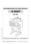
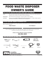
Tools and materials you may need
PHILLIPS & FLATBLADE
SCREWDRIVER
HAMMER
HACKSAW
PIPE WRENCH
PLUMBER’S PUTTY
DOWEL OR
STEEL PUNCH
2680 Orbiter Street • Brea, CA 92821 • www.anaheimmfg.com
DISHWASHER CONNECTOR KIT
POWER CORD
STRAIN RELIEF
560C485P01 REV D
IMPORTANT SAFETY INSTRUCTIONS
INSTRUCTIONS PERTAINING TO A RISK OF FIRE, ELECTRIC SHOCK OR INJURY TO
PERSONS. SAVE THESE INSTRUCTIONS.
disposer is magnetically actuated, non-magnetic
WARNING – When using electrical appliances,
basic precautions should always be followed, including the following:
1. Read all instructions before using the appliance.
2. To reduce the risk of injury, close supervision is
necessary when an appliance is used near children.
3. Do not put fingers or hands into a waste disposer.
4. Turn the power switch to the off position before
attempting to clear a jam or remove an object
from the disposer.
5. When attempting to loosen a jam in a waste disposer, use a long wooden object such as a wooden
spoon or the wooden handle of a broom or mop.
6. When attempting to remove objects from a waste
disposer use long-handled tongs or pliers. If the
tools should be used.
To reduce the risk of injury by materials that may
be expelled by a waste disposer, do not put the
following into a disposer: clam or oyster shells;
caustic drain cleaners or similar products; glass,
china or plastic; large whole bones; metal, such as
bottle caps, tin cans, aluminum foil or utensils;
hot grease or other hot liquids; whole cornhusks.
8. When not operating a disposer, leave the stopper
in place to reduce the risk of objects falling into
the disposer.
9. DO NOT operate disposer unless splash guard is
in place. (Does not apply to the Top
Control/Batch Feed units.)
10. For proper grounding instructions see the ELECTRICAL CONNECTION portion of this manual.
7.
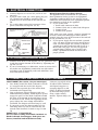
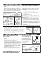
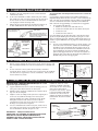
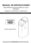
1. REMOVAL OF OLD UNIT
TYPICAL INSTRUCTIONS, YOUR MODEL MAY VARY.
Before starting this step, turn off electrical power at
the circuit breaker or fuse box.
If your old mount is the same as the mount on your
new disposer, just reverse the assembly instructions
found in section 3. If your new mount system is different, follow these instructions:
A. Use a pipe wrench to disconnect drain line where
it attaches to disposer discharge tube (see 1A).
B. Remove disposer from sink flange by turning
mount ring to the left clockwise (see 1B). If you
are unable to turn the mount ring, tap on one of
the extensions from the ring with a hammer.
Some mounting systems have tubular extensions.
Inserting a screwdriver into one tube will provide
additional leverage for turning the mount ring
(see 1B). Some disposers may require the removal
or loosening of nuts from the mount screws (see
1C). Some disposers may require the removal of a
clamp.
Caution: Be sure to support the disposer
while performing this step or it may fall
when the mounting ring is disconnected
from the mounting assembly. If your disposer is hard wired (metal shielded cable
not utilizing a wall plug), complete
steps C and D. If you utilize a plugin cord, go on to step E.
C.
D.
When disposer is removed, turn up side
down and remove electrical cover plate
(see 1D).
Use screwdriver to remove green ground
wire. Remove wire nuts from black and
E.
white power wires and separate disposer wires
from power cable wires. Loosen screws on cable
clamp and separate cable from disposer.
To remove remaining mount system from the
sink, loosen mount screws, push mount ring up.
Under it is the snap ring. Use screwdriver to pop
off ring (see 1E). Remove mount ring, protector
ring and gasket from sink flange. Some mounts
will require the unscrewing of a large ring holding
the sink flange in place. Pull sink flange up
through sink and clean off old putty from sink.
IMPORTANT: Unless you have a new
home, this is a good time to clean out the
trap and drain lines by running a drain
auger or plumber’s snake before installing
your new disposer.
1C
1A
1B
1D
1E
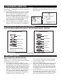
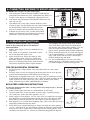
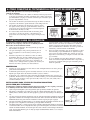
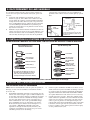
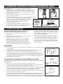
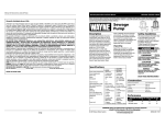
2. DISHWASHER CONNECTION
If you are utilizing a dishwasher, complete the following procedure. If dishwasher is not to be connected
go on to section 3.
A. Using a blunt instrument (steel punch or wooden
dowel), knock out entire plug (see 2A). Do not
use a screwdriver or sharp instrument. When
knockout plug falls into disposer, you may
remove it or simply grind it up when the disposer
is used. This will not damage the disposer in any
way, but may take some time to grind, over the
course of several uses. Go to Section 3.
B. Connect dishwasher hose using hose clamp. If
hose size is different, you will need a Dishwasher
Connector Kit (see 2B). Make sure all plumbing
connections are tight and in accordance with all
plumbing codes and ordinances. Run water and
check for leaks.
2B
* AIR GAP
DISHWASHER
HOSE
2A
KNOCK
OUT PLUG
DISPOSER
RUBBER
HOSE
*Air gap may not be required
for all installations. Check local
plumbing codes.
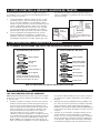
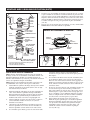
3. INSTALLATION OF MOUNTING ASSEMBLY
YOUR DISPOSER COMES WITH ONE OF THE FOLLOWING MOUNT SYSTEMS
3-Bolt Mount System
EZ Mount System
SINK FLANGE*
SINK FLANGE
SINK FLANGE GASKET
SINK FLANGE GASKET
FIBER GASKET
PROTECTOR RING
MOUNTING SCREWS (3)
SUPPORT RING
SINK MOUNT RING
MOUNT RING
TIGHTENING EARS
* An extended sink flange (Item # 3140) is
available for deep-well, cast iron sinks. (For
3-bolt mount only.)
CUSHION MOUNT
Proceed to the instructions for your type of mount system.
3-Bolt Mount System
READ COMPLETELY BEFORE STARTING
NOTE: Pay close attention to the order of mount
assembly parts, as they have been correctly assembled
by the factory. (See 3A and 3B.)
A. Disassemble the mounting assembly, as it has
been shipped, by turning the sink flange until the
projections align with the notches in the mount
ring and allow you to pull the sink flange up and
out of the remaining mount assembly. Note the
sequence of these parts as they are stacked and
refer to 3A and 3B to identify each part. Unpack
the 3 mount screws and screw them half way
through the mount ring (notice “THIS SIDE UP”
is imprinted on top of the mount ring).
B.
C.
Next, stack the rubber gasket on top of the protector ring and sit them on top of the pointed
ends of the mount screws.
Keep these assembled parts together and set aside.
Before you connect the disposer to the mount
assembly under the sink, you may want to practice engaging the groove of the Hush Cushion®
to the ridge at the bottom of the sink flange (see
3A and read Sec. 6).
Be sure your sink is clean. Pack the underside rim
of the sink flange with plumber’s putty (see 3C).
Position the sink flange so it is centered and readable as you look into your sink. Push the sink
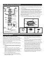
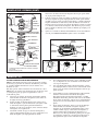
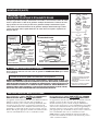
3-Bolt Mount System (continued)
3A
SINK
STOPPER*
D.
SINK FLANGE**
PLUMBER’S
PUTTY
PROJECTIONS
RIDGE
RUBBER SINK
FLANGE GASKET**
PROTECTOR RING**
MOUNTING
SCREWS**
SCREW
CLAMP**
E.
flange firmly into the sink opening to make a good seal. DO
NOT move or rotate the sink flange once seated or the seal
may be broken.
Take the remaining portion of the mount assembly, as it was
set aside and make sure that the rubber gasket is on top of
the protector ring. From under the sink, while holding the
sink flange firmly with one hand, line up the notches in the
mount ring with the projections of the sink flange. Slide the
mount assembly up onto the sink flange, past the projections and give the mount assembly a 1/4 turn, so that it will
hang by itself (see 3D).
Tighten the 3 mounting screws evenly with a screwdriver
(see 3E). DO NOT OVERTIGHTEN! Trim off excess putty.
MOUNT RING**
Mount Assembly
HUSH CUSHION®**
RIDGE
PROTECTOR
RING
DISHWASHER
DISCHARGE INLET
RUBBER
GASKET
HOPPER
SCREW
CLAMP
SCREWS
MOUNTING
SCREWS
ELBOW
FLANGE
END BELL
(ELECTRICAL
CONNECTIONS)
ELBOW
GASKET
3B
SINK
FLANGE
HUSH CUSHION
DISCHARGE
ELBOW
MOUNTING
RING
SERIAL #- RECORD ON
WARRANTY CARD
* Batch Feed Stopper looks different than the stopper illustrated.
** Mount Assembly (see 3B)
3C
3D
3E
EZ Mount System
READ COMPLETELY BEFORE STARTING
NOTE: Pay close attention to the order of mount
assembly parts, as they have been correctly assembled
by the factory. Also, reference the cushion mount
detail in illustration 3J below for the proper orientation of the cushion mount.
D.
NOTE: Try practicing this assembly before you get
under the sink to get the “feel” of how the parts fit
together.
A. Disassemble mount assembly from disposer by
turning mount ring to the left (clockwise) and
remove.
B. Raise mount ring toward top of sink flange.
Remove cushion mount. Remove mount ring. You
may want to practice installing the cushion
mount at this point before you are under the
sink. See paragraph H. Also see the “Important
Notice: Cushion Mount Detail.”
C. Unscrew support ring from sink flange and
remove fiber gasket. You are now left with sink
flange and rubber gasket.
F.
E.
G.
The rubber gasket is used instead of plumbers
putty with stainless steel sinks. Other sinks will
require putty.
If no putty is used, insert sink flange through rubber gasket into sink opening. Do not rotate sink
flange once it is seated.
If you use putty instead of the gasket, form a ring
around underside of sink flange. Insert flange into
sink opening, press down hard to squeeze out
excess putty. From under sink, trim off excess
putty flush with bottom edge of sink opening.
From underneath sink, slip fiber gasket onto
exposed sink flange. With arrows pointing up,
screw support ring onto the sink flange, hand
tighten until the sink flange will not move (see
3F). At this point you may want to insert stopper
in sink and fill with water to check sink flange
seal and insure there are no leaks.
EZ Mount System (continued)
H.
Place mount ring over sink flange and hold in place while installing cushion
mount (large side down) so the groove on the inside of cushion mount fits
over lip on sink flange, similar to putting the lid on a plastic container (see
3G, 3H & 3J). Please read important notice below.
STOPPER*
REMOVABLE
SPLASH
GUARD**
SINK
FLANGE
IMPORTANT NOTICE: CUSHION MOUNT DETAIL
RUBBER SINK
FLANGE GASKET
When the cushion mount is installed correctly, the lip of the sink flange fits into the
groove on the inside of the cushion mount and mount ring can be pulled downward over
cushion mount and will be free to rotate. The bottom bead of the cushion mount acts as
a gasket between the bottom of the sink flange and the top of the disposer. See illustration 3J.
3F
3G
SINK
3J
CUSHION MOUNT DETAIL
FIBER
GASKET
SINK
SUPPORT RING
NOTE: ARROWS
INDICATING UP
SUPPORT
RING
TOP OF SINK FLANGE
SINK
FIBER
GASKET
BOTTOM
BEAD OF
CUSHION
MOUNT
OPEN AREA, NO
OBSTRUCTION
RUBBER
GASKET
MOUNT
RING
3H
TIGHTENING
EARS‡
SUPPORT
RING
SINK
FLANGE
MOUNT RING SHOULD BE
FREE TO MOVE UP & DOWN
MOUNT RING‡
GROOVE
BOTTOM
BEAD
BOTTOM “LIP”
OF SINK
FLANGE
CUSHION
MOUNT
GROOVE
HOPPER
DISHWASHER
DISCHARGE
INLET
ELBOW GASKET
CUSHION MOUNT
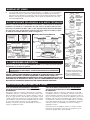
4. ELECTRICAL CONNECTIONS
Now is the time to record the SERIAL NUMBER (located on the bottom of the disposer)
onto the warranty card.
IF YOU ARE NOT FAMILIAR WITH ELECTRICAL POWER AND PROCEDURES,
CALL A QUALIFIED ELECTRICIAN
WARNING: IMPROPER CONNECTION OF THE EQUIPMENT-GROUNDING
CONDUCTOR CAN RESULT IN A RISK OF ELECTRIC SHOCK. CHECK WITH A
QUALIFIED ELECTRICIAN OR SERVICEMAN IF YOU ARE IN DOUBT AS TO
WHETHER THE APPLIANCE IS PROPERLY GROUNDED. DO NOT MODIFY THE
PLUG PROVIDED WITH THE APPLIANCE IF IT WILL NOT FIT THE OUTLET,
HAVE A PROPER OUTLET INSTALLED BY A QUALIFIED ELECTRICIAN.
ENDBELL
(ELECTRICAL
CONNECTIONS
SCREWS
ELBOW
FLANGE
DISCHARGE
ELBOW
SERIAL # – RECORD
ON WARRANTY CARD
*Batch Feed Stopper looks different than
the stopper illustrated.
**NOT used with Batch Feed units.
‡Your mount ring may look different and
not have tightening ears.
GROUNDING INSTRUCTIONS
FOR WASTE DISPOSERS EQUIPPED WITH A
GROUNDED PLUG-IN POWER CORD.
This appliance must be grounded. In the event of a
malfunction or breakdown, grounding provides a path
of least resistance for electric current to reduce the risk
of electric shock. This appliance is equipped with a
cord having an equipment-grounding conductor and a
grounding plug. The plug must be plugged into an
appropriate outlet that is properly installed and
grounded in accordance with all local codes and ordinances.
FOR WASTE DISPOSERS NOT EQUIPPED WITH A
GROUNDED PLUG-IN POWER CORD.
This appliance must be grounded. In the event of
malfunction or breakdown, grounding provides a
path of least resistance for electric current to reduce
the risk of electric shock. The power cord (to be
installed) must have an equipment-grounding
conductor and a grounding plug. The plug must be
plugged into an appropriate outlet that is properly
installed and grounded in accordance with all local
codes and ordinances.
Disconnect electric power to disposer circuit before
installation. Turn the circuit breaker to the OFF
position or remove the fuse.
4. ELECTRICAL CONNECTIONS
A.
B.
C.
Connect disposer to 110-120 Volt, 60 Hz AC current only.
If plug-in cord is used, use a three prong plug (see
4A). Ground wire should be attached to the
ground screw in the bottom of the end bell (see
4B).
Use a cable clamp strain relief connector where
power cord enters the disposer (see 4C).
Trace lead connected to this blade
and attach that lead to white wire
on disposer.
4A
RIBBED SIDE
NOTE: When viewing face of electrical plug with grounding pin at top,
the larger left blade is connected to
the identified wire.
4C
4B
RED RESET BUTTON
GROUND SCREW
TO HOUSE
CURRENT OR
POWER CORD
STRAIN
RELIEF
WIRE NUTS
REMOVE COVER
PLATE
NUT
Wiring Disposer Directly to House Current
This appliance must be connected to a grounded,
metal permanent wiring system or an equipmentgrounding conductor must be run with the circuit
conductors and connected to the equipment-grounding terminator or lead on the appliance.
A. If you use BX cable:
1. Install cable connector in hole.
2. Connect white wire to white lead of disposer.
3. Connect black.
4. Connect bare ground.
If BX cable is not used, provide a separate ground wire
to nearest cold water metal pipe or other suitable
ground, using the screw in the bottom of the end bell
for the ground wire (see 4C).
B. If your power supply does not include a ground
wire, you must provide one unless metal cable is
used. Attach a copper wire securely to disposer
ground screw and attach other end of wire to a
metal cold water pipe. Use only UL approved
ground clamp. If plastic pipe is used in your
home, a qualified electrician should install a
proper ground.
5. ATTACHING DISCHARGE ELBOW
A.
B.
Connect waste elbow to the disposer (see 5A), proceed to step
6 and then connect bottom of the elbow by tightening the
slip nut (see 5B).
If you are connecting to a dishwasher, return to section 2B. If
not, make sure all plumbing connections are tight and in
accordance with all plumbing codes and ordinances. Run
water and check for leaks.
RUBBER
GASKET
5A
5B
6. CONNECTING DISPOSER TO MOUNT ASSEMBLY
3-BOLT MOUNT (See section 3 for your mount type.)
A. Press firmly around the Hush Cushion® to ensure
it is engaged with the neck of the disposer.
B. Lubricate the top inside lip of the rubber Hush
Cushion® with a liquid soap.
C. Line up discharge elbow of disposer with trap
under mounting assembly. Guide disposer up and
engage the groove of the Hush Cushion® around
the ridge at the bottom of the sink flange (see 6A
& refer back to 3B). While still supporting the disposer, tighten the screw-clamp around Hush
Cushion®. The disposer will now hang by itself.
D. If you need to turn the disposer make sure the
sink flange does not turn. It will break the seal
created when installed. Go back to steps 5A and
5B.
IMPORTANT – PLEASE READ
Do not remove clamp from Hush Cushion® or
Hush Cushion® from hopper. Both parts are
factory installed and installation ready.
Lubricate top angled surface
of rubber Hush Cushion®
with liquid soap prior to
engaging disposer to sink
flange. Fit Hush Cushion®
lip into sink flange groove
using a slight rocking
motion. Tighten clamp (see
6B).
6A
6B
SINK
FLANGE
GROOVE
HUSH
CUSHION®
SINK FLANGE
CLAMP
HOPPER
HUSH CUSHION®
TOP ANGLED
SURFACE
CLAMP
6. CONNECTING DISPOSER TO MOUNT ASSEMBLY (continued)
EZ MOUNT (See section 3 for your mount type.)
A. Line up disposer under mounting assembly. Guide hopper
projections into mount ring slots. Turn mount ring about 1/4”
to right so that disposer is temporarily supported (see 6C).
B. Turn mount ring and disposer until disposer elbow lines up
with trap (see 6D).
C. Turn mount ring to the right (counter-clockwise) until
it locks up tight. Tap the mount ring ears with a hammer until
the lock position is achieved. Hopper projections
must be to extreme left of mounting slots (see 6E).
D. If mount ring is hard to turn, you may add a small
amount of petroleum jelly or liquid soap to hopper
projections. Run water and check for leaks.
6C
6D
SLOT
PROJECTION
ELBOW
TRAP
6E
6F
LOCKING DETAIL
HOPPER PROJECTION IN
“SUPPORTED” POSITION
HOPPER PROJECTION IN
“LOCK” POSITION
MOUNT RING
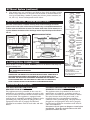
7. OPERATING INSTRUCTIONS
The Anti-Jam Swivel Impellers make a clicking
sound as they swing into place. This indicates
normal operation.
A. Remove sink stopper. Turn on a medium flow of
cold water.
B. Turn switch to ON position; your motor is turning at full speed and ready to use.
C. Scrape in food waste. Down the drain go table
scraps, peelings, rinds, seeds, pits, small bones
and coffee grounds. To speed up food waste disposal, cut or break up large bones, rinds and cobs.
Large bones and fibrous husks require consider-
D.
E.
able grinding time and are more easily thrown
away with other trash. Do not be alarmed that
the disposer slows down while grinding. The disposer is actually increasing torque (grinding
power) and is operating under normal conditions.
Before turning disposer off, let water and disposer
run for approximately 15 seconds after shredding
stops. This assures that all waste is thoroughly
flushed through trap and drain.
It is not recommended to use hot water while
running disposer. Cold water will keep waste and
fats solid so disposer can flush away particles.
TIPS FOR SUCCESSFUL OPERATION
A.
B.
C.
7A
Be sure disposer is empty before using your dishwasher so it may drain
properly.
You may want to leave the stopper in the drain when not in use to prevent
utensils and foreign objects from falling into the disposer.
Your disposer is ruggedly built to give you many years of trouble free service.
It will handle all normal food wastes, but it will NOT grind or dispose of such
items as plastic, tin cans, bottle caps, glass, china, leather, cloth, rubber,
string, clam and oyster shells, aluminum foil or feathers.
7B
BATCH FEED OPERATING INSTRUCTIONS
The Anti-Jam Swivel Impellers make a clicking sound as they swing into place. This indicates normal operation.
A.
B.
C.
D.
E.
Remove sink stopper and turn on a medium flow of cold water.
Scrape in food waste. Down the drain go table scraps, vegetable peelings,
cobs, rinds, pits, bones and coffee grounds. (see 7A)
Insert stopper to start disposer. (see 7B) One of the two small slots in stopper
base must line up with switch plunger inside the neck of the disposer. Push
down firmly to turn the disposer on. Lift stopper to shut the disposer off.
Run disposer for 15 seconds after shredding stops. This assures that all waste is
thoroughly flushed through the drain.
To fill sink, insert stopper and align the largest slot with the switch plunger.
(see 7C) Push down to seal sink without starting the disposer. When medium
sized slot (see 7B) in stopper base is lined up with the switch plunger, water
can drain, but tableware, etc., cannot be accidentally dropped into disposer.
MEDIUM
SLOT
SMALL
SLOT
7C
LARGE
SLOT
8. TROUBLESHOOTING
Before seeking repair or replacement, we recommend that you review the following:
LOUD NOISES: (Other than those during grinding of
small bones and fruit pits): These are usually caused
by accidental entry of a spoon, bottle cap or other foreign object. To correct this, turn off electrical switch
and water. After disposer has stopped, remove *splash
guard, remove object with long handled tongs, and
replace *splash guard.
UNIT DOES NOT START: Unplug power cord or turn
either the wall switch or breaker box switch to “OFF”
position, depending on your model and wiring configuration. Remove stopper and/or *splash guard. Check
to see if turntable will rotate freely using a wooden
broom handle. If turntable rotates freely, replace
*splash guard and check re-set button to see if it has
been tripped. Re-set button is red and located opposite discharge elbow, near the bottom (see 8A). Push
button in until it clicks and remains depressed.
If re-set button has not been tripped, check for shorted or broken wire connecting to disposer. Check
electrical power switch, fuse box or circuit breaker. If
wiring and electrical components are intact, the unit
may have internal problems that require service or
replacement.
* Splash guard not used on Top Control/Batch Feed
unit.
IF TURNTABLE DOES NOT ROTATE FREELY: Turn
off disposer, then check for any foreign object lodged
between the turntable and grind ring. Dislodge object
by rotating table with a wooden broom handle and
remove object. (see 8B) If no foreign object is present,
there may be internal problems.
LEAKS: If the unit leaks at the top, it may be due to:
1. Improper seating of sink flange (gasket centering,
putty or tightening).
2. Support ring not tightened properly.
3. Defective or improperly installed cushion mount.
If unit leaks at the waste elbow, leak may be due to
improper tightening of elbow flange screws.
8A
8B
REMOVE
SPLASH
GUARD
RESET
BUTTON
SERIAL
NUMBER
TURNTABLE
Call our toll free Help Line with any questions
800-854-3229
9. CLEANING AND MAINTENANCE
DO NOT ATTEMPT TO LUBRICATE YOUR DISPOSER!
The motor is permanently lubricated. The disposer is
self cleaning and scours its internal parts with each
use.
NEVER put lye or chemical drain cleaners into the disposer, as they cause serious corrosion of metal parts. If
used, resulting damage can be easily detected and all
warranties are void. Mineral deposits from your water
can form on the stainless steel turntable, giving the
appearance of rust. DO NOT BE ALARMED, the stainless steel turntables used will not corrode.
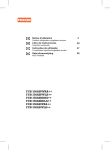
GUÍA DEL PROPIETARIO
DEL TRITURADOR DE
DESPERDICIOS DE COMIDA
Vea la informacíon específica para su nuevo triturador
NOTA:
Este triturador de desperdicios de comida ha sido diseñado para funcionar exclusivamente con 110-120 voltios,
60 Hz. El uso de cualquier otro voltaje o frecuencia afectará negativamente el funcionamiento.
IMPORTANTE:
Lea todas las instrucciones con atención. Guarde esta guía para cualquier consulta en el futuro.
PRECAUCIÓN:
Asegúrese de repasar PRIMERO LAS INSTRUCCIONES DE SEGURIDAD SOBRE LOS PELIGROS DE FUEGO,
TOQUES ELÉCTRICOS O LESIONES A PERSONAS antes de instalar el triturador.
Anote en los espacios provistos la información del triturador de comida
Guarde su factura de venta, comprobante de venta, cheque cancelado u otra constancia de compra para verificar la fecha de compra original para efectos de la garantiia.
Numero de Modelo*
Numero de Serie*
* La información anterior se encuentra en la etiqueta adherida a la parte inferior del triturador.
Para conveniencia suya, anote los números de modelo y de serie antes de la instalación.
Llame gratis a nuestra linea de asistencia para atender cualquier pregunta.
800-854-3229
Herramientas y materiales que podrá necesitar
DESTORNILLADOR PHILLIPS Y
DE HOJA PLANA
MARTILLO
SIERRA PARA METALES
LLAVE PARA TUBOS
JUEGO DE CONECTORES PARA
MÁQUINAS LAVADORAS DE TRASTOS
MASILLA DE PLOMERO
PUNZÓN DE
ESPIGA O ACERO
2680 Orbiter Street • Brea, CA 92821 • www.anaheimmfg.com
CORDÓN DE
SUMINISTRO
ALIVIADOR DE TENSIÓN
560C485P01 REV D
INSTRUCCIONES DE SEGURIDAD IMPORTANTES
INSTRUCCIONES CONCERNIENTES A RIESGO DE FUEGO, CHOQUE ELÉCTRICO O LESIONES A
PERSONAS. GUARDE ESTAS INSTRUCCIONES.
ADVERTENCIA – Cuando utilice aparatos eléctricos,
siempre debe seguir precauciones básicas, entre las cuales
se incluyen las siguientes:
1.
Lea todas las instrucciones antes de utilizar el aparato.
2.
Para reducir el riesgo de lesiones, es necesaria la cercana
supervisión cuando un aparato es utilizado cerca de niños.
3.
No ponga dedos o manos dentro de un triturador de basura.
4.
Ponga el interruptor a la posición apagada antes de intentar
desatorar un objeto o remover un objeto del triturador.
5.
Cuando intente aflojar una obstrucción en el triturador de
basura, utilice un objeto largo de madera tal como una
cuchara de madera o el mango de madera de una escoba o
trapeador.
6.
Cuando intente remover objetos del triturador de basura,
utilice pinzas o alicates de mango largo. Si el triturador es
magnéticamente accionado, se deberán usar herramientas
no-magnéticas.
7.
Para reducir el riesgo de lesiones por materiales que puedan
ser expulsados por el triturador de basura, no coloque los
siguientes dentro del triturador: conchas de ostiones o almejas; limpiadores de drenaje cáusticos o productos similares;
vidrio, loza o plástico; huesos grandes y enteros; metales,
tales como tapas de botellas, latas, papel de aluminio o utensilios; grasa caliente u otros líquidos calientes; cáscaras
enteras de maíz.
8.
Cuando no esté operando el triturador, coloque el tapón en
su lugar para reducir el riesgo de que caigan objetos dentro
del triturador.
9.
NO opere el triturador a menos que la salpicadera de protección esté en su lugar. (Esto no aplica a las unidades del
Control Superior/Lote de Alimentación.)
10.
Para las instrucciones de conectar a tierra, vea la porción
CONEXIÓN ELÉCTRICA de este manual.
1. CÓMO QUITAR UNA UNIDAD VIEJA
INSTRUCCIONES TÍPICAS. SU MODELO PODRÍA SER DIFERENTE.
Antes de iniciar esta tarea, corte la electridad a partir del
interruptor del circuito o caja de fusibles.
Si el conjunto de montaje es el mismo en su triturador nuevo,
siga las instrucciones de montaje de la seccion 3, a la inversa. Si
el nuevo sistema de montaje es diferente, siga las siguientes
instrucciones:
A.
Use una llave para tubos para desconectar la línea de drenaje
en donde está conectada al tubo de desagüe del triturador
(vea 1A).
B.
Quite el triturador de la brida del fregadero girando a la
izquierda (en el sentido opuesto a las agujas del reloj (vea
1B). Si no puede darle vuelta al anillo, golpee ligeramente
una de las extensiones con un martillo. Algunos sistemas de
montaje tienen extensiones tubulares. Introduzca un
destornillador a través del tubo y úselo como palanca para
darle vuelta al anillo (vea 1B). En algunos trituradores es
necesario quitar las tuercas en los tornillos de montaje, y
luego quite el triturador viejo (vea 1C). En el caso de algunos
trituradores, es necesario quitar primero la abrazadera.
E.
Afloje los tornillos de montaje y empuje el anillo de montura hacia arriba. Debajo de éste se encuentra el anillo de
resorte. Desprenda el anillo con un destornillador (vea 1E).
Quite el anillo de montura, el anillo protector y la empaquetadura de la brida del fregadero. Algunas monturas van a
necesitar que se quite el anillo de montura grande de la brida
del fregadero. Jale la brida del fregadero hacia arriba a través
del fregadero y raspe y quite la masilla vieja.
IMPORTANTE: A menos que su casa sea nueva,
aproveche esta oportunidad para limpiar todas las
líneas de las trampas y los drenajes, introduciendo
una barrena de drenaje o una culebra de plomero
antes de instalar su nuevo triturador.
1A
1B
1D
1E
Precaución: Asegúrese de apoyar el triturador mientras lleva a cabo este paso para evitar que se caiga al
desconectarse el anillo de montura del conjunto de
montaje. Si el cableado está integrado al dispositivo
(un cable protegido que no usa un enchufe de
pared), complete los pasos C y D. Si usa un cordón
enchufable, prosiga al paso E.
C.
Después de quitar el triturador, colóquelo boca
abajo y quite la placa de cubierta eléctrica (vea 1D).
D.
Use un destornillador para quitar el alambre de tierra verde. Quite las tuercas para alambre de los
alambres de suministro negro y blanco y separe los
alambres del triturador de los alambres del cable de
suministro. Afloje los tornillos en la abrazadera del
cable y separe el cable del triturador.
1C
2. COMO CONECTAR LA MÁQUINA LAVADORA DE TRASTOS
las conexiones de tuberías estén bien apretadas según los
códigos y regulamentos de plomería. Deje correr el agua el y
detecte si hay fugas.
Si usa un máquina lavadora de trastos, complete el siguiente
procedimiento. Si no está conectada a una máquina lavadora de
trastos, prosiga a la sección 3.
A.
B.
Con un instrumento desafilado (punzón de acero o espiga
de madera), golpee y saque todo el tapón provisional (vea
2A). No use un destornillador u otro instrumento afilado.
Cuando el tapón provisional cae dentro del triturador, puede
retirarlo o simplemente triturarlo cuando use el triturador.
Esto no dañará el triturador en lo absoluto, pero es posible
que tome algún tiempo para desmenuzarlo por completo,
quizás después de que lo use varias veces.Pasa a la sección 3.
2B
BRECHA DE AIRE*
2A
TRITURADOR
TAPÓN
PROVISIONAL
Conecte la manguera de la máquina lavadora de trastos
usandola abrazadera de la manguera. Si el tamaño de la
manguera es diferente, necesitará un enchufe de conectores
para máquina de lavar trastos (vea 2B). Asegúese que todas
MANGUERA
DE LA
MÁQUINA
LAVADORA
DE TRASTOS
MANGUERA
DE CAUCHO
* Puede que no sea necesaria la brecha de aire
para todas las instalaciones. Revise los códigos
de plomería locales.
3. INSTALACIÓN DEL CONJUNTO DE MONTAJE
SU TRITURADOR ESTA EQUIPADO CON UNO DE LOS SIGUIENTES SISTEMAS DE MONTAJE
Sistema De Montaje De 3 Pernos
Sistema De Montaje “EZ” (Fácil)
BRIDA DEL FREGADERO*
BRIDA DEL FREGADERO
EMPAQUETADURA
DE CAUCHO
EMPAQUETADURA DE BRIDA
DE CAUCHO DEL FREGADERO
ANILLO PROTECTOR
EMPAQUETADURA DE FIBRA
TORNILLOS DE MONTAJE (3)
ANILLO DE APOYO
ANILLO DE MONTURA
ANILLO DE MONTURA
ALETAS PARA APRETAR
* Un reborde prolongado (articulo # 3140) está
disponible para fregaderos profundos de hierro
fundido. (Sólo para montaje de tres pernos.)
MONTURA DE COJIN
Siga las indicaciones del tipo de montaje que usted tenga.
MONTAJE DE 3 PERNOS
LEA POR COMPLETO ANTES DE COMENZAR
ra de caucho encima del anillo protector y luego coloque los
dos encima de los extremos puntiagudos de los tornillos de
montura.
NOTA: Póngale mucha atención al orden de piezas del conjunto
de montaje, ya que han sido armadas debidamente por la fábrica. (Vea 3A y 3B.)
A.
Desarme el conjunto de montaje, tal como ha sido enviado
de fábrica, dándole vuelta a la brida del fregadero hasta que
las proyecciones queden alineadas con las muescas en el
anillo de montura y pueda halar la brida del fregadero hacia
arriba y retirarla del resto del conjunto de montaje. Tome
nota de la secuencia de estas piezas, tal como están colocadas una encima de la otra y consulte 3A y 3B para
identificar cada pieza. Desempaque los 3 tornillos de montura y atorníllelos hasta la mitad a través del anillo de montura
(tome nota de la advertencia "THIS SIDE UP" ("ESTE LADO
HACIA ARRIBA”) que está impresa en la parte superior del
anillo de montura). Seguidamente, coloque la empaquetadu-
B.
Mantenga estas piezas ensambladas juntas y póngalas a un
lado. Antes de conectar el triturador al conjunto de montaje
debajo del fregadero, quizás querrá practicar engranar la
ESTRÍA del cojín silenciador Hush Cushion® al REBORDE en
la parte inferior de la brida del fregadero (consulte 3A y lea la
sección 6).
C.
Asegúrese de que el fregadero esté limpio. Rellene el borde
del lado inferior de la brida del fregadero con masilla de
plomero (vea 3C). Coloque la brida del fregadero de manera
que quede centrada y se pueda leer cuando usted mira dentro del fregadero. Empuje la brida del fregadero firmemente
en la abertura del fregadero para crear un sello bueno. NO
MONTAJE DE 3 PERNOS (CONT.)
mueva ni le dé vuelta a la brida del fregadero una vez que quede asentada, ya que puede romper el sello.
3A
FREGADERO
D.
Tome la porción que queda del conjunto de montaje, tal como la puso a
un lado y asegúrese de que la empaquetadura de caucho quede encima
del anillo protector. Desde por debajo del fregadero, sostenga la brida del
fregadero firmemente en una mano y alinee las muescas en el anillo de
montura con las proyecciones de la brida del fregadero. Deslice el conjunto de montaje sobre la brida del fregadero, más allá de las proyecciones y
déle al conjunto de montaje 1/4 de vuelta, de manera que cuelgue por sí
solo (vea 3D).
E.
Apriete los 3 tornillos de montaje uniformemente con un destornillador
(vea 3E). ¡NO APRIETE DEMASIADO! Quite el exceso de masilla.
TAPÓN*
BRIDA DEL
FREGADERO**
MASILLA DE
PLOMERO
PROYECCIONES
REBORDE
EMPAQUETADURA DE BRIDA
DE CAUCHO DEL FREGADERO**
ANILLO PROTECTOR**
TORNILLOS
DE MONTAJE**
ABRAZADERA
DE TORNILLO**
REBORDE
TOLVA
ANILLO DE MONTURA**
Conjunto de Montaje
COJÍN SILENCIADOR**
ANILLO
PROTECTOR
EMPAQUETADURA
DE CAUCHO
ORIFICIO DE DESCARGA
DE LA MÁQUINA
LAVADORA DE TRASTOS
ABRAZADERA
DE TORNILLO
TORNILLOS
TORNILLOS
DE MONTAJE
BRIDA
DEL CODO
CAMPANA DE
PUNTA
(CONEXIONES
ELÉCTRICAS)
3B
BRIDA DEL
FREGADERO
COJÍN SILENCIADOR
CODO DE
DESCARGA
ANILLO DE
MONTURA
EMPAQUETADURA
DEL CODO
NUMERO DE SERIE - ANOTAR EN
LA TARJETA DE GARANTÍA.
* La apariencia del tapón del Batch Feed es diferente a la del tapón
que se ilustra.
** Conjunto de Montaje (vea 3B)
3C
3D
3E
MONTAJE “EZ”
LEA POR COMPLETO ANTES DE COMENZAR
NOTA: Ponga mucha atención al orden de piezas del conjunto
de montaje, ya que han sido armadas debidamente por la fábrica. Consulte también la ilustración (3D) de detalles de la
montura de cojín
más abajo para la debida orientación de la montura de cojín.l
NOTA: Trate de practicar esta instalación antes de meterse debajo del fregadero para que pueda “experimentar” como se
acomodan las partes.
A.
Desconecte el conjunto de montaje del triturador dándole
vuelta al anillo de montura a la izquierda (en el sentido de
las agujas del reloj) y quitándolo.
B.
Levante el anillo de montura hacia la parte superior de la
brida del fregadero. Quite la montura de cojín. Quite el anillo de montura. Tal vez quiera practicar instalando la
montura de cojín en este momento, antes de meterse debajo
del fregadero. Vea el párrafo "H".
C.
Destornille el anillo de apoyo de la brida del fregadero y
quite la empaquetadura de fibra. Lo que le queda ahora es la
brida del fregadero y la empaquetadura de caucho.
D.
Use la empaquetadura de caucho, en vez de masilla de plomero, con fregaderos de acero inoxidable. Use la masilla con
otros tipos de fregaderos.
E.
Si no usa masilla, introduzca la brida del fregadero a través
de la empaquetadura de caucho dentro de la abertura del fregadero. No le dé vuelta a la brida del fregadero una vez que
quede asentada.
F.
Si usa masilla en vez de la empaquetadura, forme un anillo
alrededor del lado inferior de la brida del fregadero.
Introduzca la brida en la abertura del fregadero y oprima
firmemente hacia abajo para hacer salir el exceso de masilla.
Desde debajo del fregadero, quite el exceso de masilla hasta
que quede a ras con el borde inferior de la abertura del fregadero.
G.
Desde debajo del fregadero, deslice y coloque la empaquetadura de fibra sobre la brida de fregadero expuesta.
Asegúrese de que las flechas apunten hacia arriba, y luego
tornille el anillo de apoyo sobre la brida del fregadero y
aprétela a mano hasta que la brida del fregadero no se
mueva (vea 3A). Ahora posiblemente querrá poner el tapón
en el fregadero y llenar éste con agua para verificar que no
haya pérdidas de agua a través de la brida del fregadero.
MONTAJE “EZ” (CONT.)
H.
Coloque el anillo de montura sobre la brida del fregadero y sosténgalo en esa posición mientras instala la montura de cojín (el lado grande hacia abajo) de manera que la estría en la
parte interior de la montura de cojín encaje sobre el borde en la brida del fregadero, similar a
cuando coloca una tapa en un envase plástico (vea el detalle de la montura de cojín y 3B).
Vea NOTA IMPORTANTE.
TAPÓN*
PROTECTOR
ANTISALPICADUA
DESMONTABLE**
BRIDA DEL
FREGADERO
NOTA IMPORTANTE RELACIONADA A SU NUEVO TRITURADOR
EMPAQUETADURA
DE BRIDA DE
CAUCHO DEL
FREGADERO
Cuándo el cojín de montura esta instalado correctamente, el labio inferior de la brida del
fregadero se acomoda en el canal interno del cojín, entonces el anillo metalico de montura puede ser jalado hacia abajo sobre el cojín dejandolo voltear libremente. El reborde
del cojín actua como empaquetadura sellando la porción de abajo de la brida y la parte
de arriba de el triturador. Para más detalles vea figura 3J.
3F
3G
3J
MONTURA DE COJIN EN DETALLE
FREGADERO
EMPAQUETADURA
DE FIBRA
FREGADERO
PARTE SUPERIOR DE LA
BRIDA DEL FREGADERO
FREGADERO
EMPAQUETADURA DE
FIBRA
REBORDE DE
LA MONTURA
DE TIGUACION
ÁREA ABIERTA, SIN
OBSTRUCCIONES
3H
ANILLO DE
APOYO
ALETAS PARA
APRETAR‡
ANILLO DE
APOYO
BRIDA DEL
FREGADERO
EL ANILLO DE MONTURA DEBE
MOVERSE LIBREMENTE HACIA
ARRIBA Y HACIA ABAJO
ANILLO DE
MONTURA‡
ANILLO DE
MONTURA
EMPAQUETADURA
DE CAUCHO
ANILLO DE
APOYO NOTA:
LAS FLECHAS
INDICAN HACIA
ARRIBA
“LABIO”
INFERIOR DE
LA BRIDA DEL
FREGADERO
ESTRIA
MONTURA DE
COJIN
ESTRIA
TOLVA
REBORDE
MONTURA DE COJIN
4. CONEXIONES ELÉCTRICAS
Ahora es el momento de anotar el NÚMERO DE SERIE (se encuentra en la parte inferior
del triturador) en la tarjeta de garantía.
SI NO ESTÁ FAMILIARIZADO CON EL SUMINISTRO ELÉCTRICO Y LOS
PROCEDIMIENTOS ELÉCTRICOS, LLAME A UN ELECTRICISTA ACREDITADO.
ADVERTENCIA: LA CONEXIÓN INDEBIDA DEL CONDUCTOR QUE CONECTA EL
EQUIPO A TIERRA PUEDE PRODUCIR UN RIESGO DE CHOQUE ELÉCTRICO. VERIFIQUE
CON UN ELECTRICISTA O TÉCNICO ACREDITADO SI TIENE DUDAS SOBRE SI SU
ARTEFACTO ESTÁ DEBIDAMENTE CONECTADO A TIERRA. NO MODIFIQUE EL ENCHUFE
QUE VIENE CON EL ARTEFACTO SI NO SE AJUSTA AL TOMACORRIENTE. PÍDALE A UN
ELECTRICISTA ACREDITADO QUE INSTALE UN TOMACORRIENTE ADECUADO.
EMPAQUETADURA
DEL CODO
COMPANA
DE PUNTA
(CONEXIONES
ELECTRICAS)
ORIFICIO DE
DESCARGA DE
LA MAQUINA
LAVADORA DE
TRASTOS
TORNILLOS
BRIDA
DEL
CODO
CODO DE
DESCARGA
NUMERO DE SERIE ANOTAR EN LA TARJETA
DE GARANTIA.
* La apariencia del tapón del Batch Feed
es diferente a la del tapón que se ilustra.
** No lo use con unidades Batch Feed.
‡ Su anillo de montura puede verse
diferente y no tener aletas para apretar.
INSTRUCCIONES PARA CONECTAR A TIERRA
PARA TRITURADORES DE DESPERDICIOS EQUIPADOS
CON UN ENCHUFE CONECTADO A TIERRA EN EL CORDÓN
DE SUMINISTRO.
Este artefacto debe ser conectado a tierra. En caso de un funcionamiento defectuoso o una falla, la conexión a tierra ofrece
una vía de menos resistencia a la corriente eléctrica y reduce el
riesgo de toques eléctricos. Este artefacto está equipado con un
cordón que tiene un conductor para conectar el equipo a tierra
y un enchufe de conexión a tierra. El enchufe debe ser conectado a un tomacorriente adecuado que esté debidamente
instalado y conectado a tierra de conformidad con todos los
códigos y reglamentos locales.
PARA TRITURADORES DE DESPERDICIOS NO EQUIPADOS
CON UN ENCHUFE CONECTADO A TIERRA EN EL CORDÓN
DE SUMINISTRO.
Este artefacto debe ser conectado a tierra. En caso de un funcionamiento defectuoso o una falla, la conexión a tierra ofrece
una vía de menos resistencia a la corriente eléctrica y reduce el
riesgo de toques eléctricos. El cordón de suministro (que va a ser
instalado) debe de tener un conductor para conectar a tierra y
un enchufe de conexión a tierra. El enchufe debe ser conectado
a un tomacorriente adecuado que esté debidamente instalado y
conectado a tierra de conformidad con todos los códigos y
reglamentos locales.
NOTA: Desconecte el suministro eléctrico al circuito del triturador antes de la instalación. Coloque el cortacircuitos en la
posición de apagado OFF o quite el fusible.
4. CONEXIONES ELÉCTRICAS (cont.)
A.
B.
C.
Conecte el triturador sólo a corriente de 110-120 voltios, 60
Hz AC.
Si usa un cordón enchufable, use un enchufe de tres dientes
(vea 4A). El alambre tornillo de tierra debe estar conectado al
tornillo en la parte inferior de la campana de punta (vea 4B).
Use un conector aliviador de tensión de alivio con abrazadera
de cable en el punto en el cual el cordón de suministro entra
al triturador (vea 4C).
Siga el recorrido del conductor
conectado a este diente y conecte
ese conductor al alambre blanco
del triturador.
4A
LADO
ACANALADO
NOTA: Al mirar la cara del enchufe
eléctrico con la patilla de tierra
hacia arriba, el diente mas grande
se conecta al alambre.
4C
4B
BOTÓN DE REAJUSTE
“RESET” ROJO
TORNILLO DE
TIERRA
A LA CORRIENTE
CASERA O EL
CORDÓN DE
SUMINISTRO
ALIVIADOR
DE
TENSION
TUERCAS PARA
ALAMBRES
QUITE LA PLACA
DE CUBIERTA
TUERCA
Si está conectando el cableado de su triturador directamente a la corriente casera:
Este artefacto debe conectarse a un sistema de cableado permanente, metálico, y conectado a tierra; o se debe tender un
conductor para conectar el equipo a tierra junto con los conductores de circuito y se debe conectar al borne o conductor que
conecta el artefacto a tierra.
A.
Si usa cable BX:
1. Instale el conector de cable en el orificio.
2. Conecte el alambre blanco al conductor blanco del
triturador.
3. Conecte el negro.
4. Conecte el alambre de tierra.
Si no usa el cable BX, provea un alambre de tierra separado a la
tubería metálica de agua fría más cercana, u otra linea de tierra adecuada usando el tornillo en la campana de punta inferior para el
alambre de tierra (vea 4C).
B.
Si su suministro eléctrico no incluye un alambre de tierra,
usted debe suministrar uno a menos que use cable metálico.
Conecte firmemente un alambre de cobre al tornillo de tierra
del triturador y conecte la otra punta del alambre a una
tubería metálica de agua fría. Use sólo una abrazadera de tierra aprobada por la asociación Underwriters Laboratories (UL)
de los EE.UU. Si usa tubería plástica en su casa, llame a un
electricista acreditado para que instale la conexión a tierra
debidamente.
5. CÓMO CONECTAR EL CODO DE DESCARGA
A.
Conecte el codo de desperdicios al triturador (vea 5A), prosiga al paso 6, y
luego conecte la parte inferior del codo apretando la
tuerca deslizante (vea 5B).
B.
Si está haciendo una conexión a una maquina para lavar trastos, regrese a
la sección 2B. En caso contrario, asegúrese que todas las conexiones de
tuberiás estén bien apretadas según los códigos y reglamentos de plomería.
Deje correr el agua y detecte si hay fugas.
EMPAQUETADURA
DEL CODO
5A
5B
6. CÓMO CONECTAR EL TRITURADOR AL CONJUNTO DE MONTAJE
Montaje de 3 pernos (Consulte la sección 3 para
sutipode de montaje.)
A. Presione firmemente alrededor del cojín silenciador Hush
Cushion® para asegurar que esté engranado con el cuello del
triturador.
B.
Lubrique el reborde interior superior del cojín silenciador
Hush Cushion® de caucho con jabón líquido.
C.
Alinee el codo de descarga del triturador con la trampa que
se encuentra debajo del conjunto de montaje. Guíe el triturador hacia arriba y engrane la RANURA del cojín silenciador
Hush Cushion® alrededor del REBORDE en la parte inferior
de la brida del fregadero (vea 6A y consulte 3B). Siga apoyando el triturador, y ajuste la abrazadera de tornillo alrededor
del cojín silenciador Hush Cushion®. Ahora el triturador
podrá mantenerse colgado por sí solo.
D.
Si necesita girar el triturador, asegúrese de que la brida del
fregadero no gire, ya que romperá el sello creado cuando se
instaló. Vuelva a los pasos 5A y 5B.
IMPORTANTE – ¡POR FAVOR LEER!
NO REMUEVAN LA ABRAZADERA DE EL COJíN SILENCIADOR HUSH CUSHION® O DE LA TOLVA, LAS DOS
PARTES FUERON INSTALADAS EN LA FACTORíA Y
ESTAN LISTAS PARA LA INSTALACIóN.
Lubriqué la área ángular de caucho de el cojín silenciador Hush
Cushion® con jabón líquido
antes de engranar el triturador a
la brida del fregadoro. Acople el
labío de el cojín Hush Cushion®
en la ranura de la brida del fregadero usando un movimiento
ligero y suave. Apriete la
abrazadera (vea 6B).
6A
6B
RANURA DE
LA BRIDA DEL
FREGADERO
COJÍN
SILENCIADOR
BRIDA DEL
FREGADERO
ABRAZADERA
TOLVA
HUSH CUSHION®
LA AREA ANGULAR
6. CÓMO CONECTAR EL TRITURADOR AL CONJUNTO DE MONTAJE (cont.)
Montaje “EZ” (Consulte la sección 3 para identifiguar
sutipode de montaje.)
A. Alinee el triturador debajo del conjunto de montaje. Guíe las proyecciones
de la tolva en las ranuras del anillo de montura. Gire el anillo de montura
aproximadamente 1/4 pulg. a la derecha de manera que el triturador quede
apoyado temporalmente (vea 6C).
B.
Gire el anillo de montura y el triturador hasta que las líneas de salida de
desperdicios del triturador queden alineadas con la trampa (vea 6D).
C.
Gire el anillo de montura a la derecha (en el sentido opuesto
alas agujas del reloj) hasta que quede firmemente trabado. Las
proyecciones de la tolva deben quedar a la extrema izquierda
de las ranuras de montaje (vea 6E).
D.
6C
6D
ABERTURA
PROYECCIÓN
DE TOLVA
CODO DE
DESCARGA
TRAMPA
6E
6F
DETALLE DE TRABA
PROYECCIÓN DE TOLVA EN
POSICIÓN "APOYADA"
Si le cuesta trabajo darle vuelta al anillo de montura, puede
poner un poco de jalea de petróleo o jabón líquido a las
proyecciones de la tolva. Haga correr el agua y verifique si hay
fugas.
PROYECCIÓN DE TOLVA EN
POSICIÓN "TRABADA"
ANILLO DE
MONTURA
7. INSTRUCCIONES DE OPERACIÓN
Los impulsores giratorios antiatascamiento hacen un
sonido de "clic" al girar y colocarse en su debida posición.
Esto indica un funcionamiento normal.
A. Quite el tapón del fregadero. Abra el agua hasta que logre un
flujo mediano de agua fría.
B.
Coloque el interruptor en la posición prendida "ON". El
motor está girando a toda velocidad y está listo para ser
usado.
C. Introduzca desperdicios de comida. Las sobras de comida,
mondaduras, mazorcas, cáscaras, semillas, huesos de frutas,
huesos de carne pequeños y granos de café, bajarán por el
drenaje. Para acelerar la disposición de los desperdicios de
comida, corte o deshaga los huesos grandes, las cáscaras y las
mazorcas. Los huesos grandes y las cáscaras fibrosas
D.
E.
requieren mucho tiempo para triturar, y es más fácil simplemente botarlos con el resto de la basura. No se alarme si el
artefacto pierde velocidad al triturar. En realidad, el triturador está aumentando el momento de torsión (potencia de
trituración) y está funcionando normalmente.
Antes de apagar el triturador, deje que el agua fluya y el triturador funcione por aproximadamente 15 segundos después
que la acción de triturar termine. Esto asegura que todos los
desperdicios sean drenados por completo a través de la trampa y el drenaje.
No se recomienda usar agua caliente mientras está funcionando el triturador. El agua fría mantendrá los desperdicios y
las grasas en condición sólida para que el triturador pueda
drenar las partículas.
7A
SUGERENCIAS
A.
Asegúrese de que el triturador esté vacío antes de usar su máquina lavadora de trastos para que
pueda drenarse debidamente.
B.
Posiblemente querrá dejar el tapón en el drenaje cuando no esté en uso el triturador para
impedir que caigan dentro del triturador utensilios y objetos extraños.
C.
Su triturador es de construcción sólida y duradera para brindarle muchos años de servicio sin
problemas. Triturará todos los desperdicios de comida normales, pero NO triturará ni eliminará
objetos tales como el plástico, latas, tapas de botellas, vidrio, loza, cuero, tela, caucho, hilos o
conchas de almejas u ostras.
7B
INSTRUCCIONES PARA UTILIZAR EL PROCESO DISCONTINUO
(BATCH FEED) DEL TRITURADOR
Los impulsores giratorios antiatascamiento hacen un sonido de “clic” al girar y colocarse
en su debida posición. Esto indica un funcionamiento normal.
A.
Quite el tapón del fregadero y abra el agua hasta que logre un flujo mediano de agua fría.
B.
Introduzca los desperdicios de comida. Las sobras de comida, mondaduras, mazorcas, cáscaras,
semillas, huesos de frutas, huesos de carne pequeños y granos de café, bajarán por el drenaje (vea
7A).
C. Coloque el tapón para arrancar el triturador (vea 7B). Una de las aberturas pequeñas en la base del
tapón debe coincidir con el interruptor del desatascador dentro del cuello del triturador. Empuje
firmemente hacia abajo para arrancar el triturador. Levante el tapón para que se apague.
D. Deje que el triturador siga funcionando por 15 segundos después de terminar de triturar. Esto asegura que todos los desperdicios sean llevados por el agua dentro del drenaje.
E.
Para llenar el fregadero, coloque el tapón y haga coincidir la abertura más grande con el interruptor del desatascador (vea 7C). Empuje hacia abajo para sellar el fregadero sin arrancar el triturador.
Cuando la abertura mediana (vea 7B) del tapón de la base coincida con el interruptor del desatascador, el agua puede drenarse, pero no deje que caigan accidentalmente cubiertos otros u objetos
dentro del triturador.
ABERTURA
MEDIANA
ABERTURA
PEQUENA
7C
ABERTURA
GRANDE
8. DIAGNÓSTICO Y LOCALIZACIÓN DE FALLAS
Antes de tratar de reparar o reemplazar, recomendamos
que estudie lo siguiente:
RUIDOS FUERTES: (Además de los causados cuando se trituran
huesos pequeños y huesos de frutas): Normalmente, estos son
producidos cuando una cuchara, tapa de botella u otro objeto
extraño es introducido accidentalmente. Para corregir esto,
apague el interruptor eléctrico y cierre el agua. Después de que
el triturador se haya detenido por completo, retire el objeto con
tenazas de mango largo.
LA UNIDAD NO ARRANCA: Desenchufe el cordón de suministro y, dependiendo de su modelo y la configuración de
cableado, coloque el interruptor de pared o el interruptor en la
caja de cortacircuitos en la posición apagada OFF. Verifique que
el disco de cuchillas gire libremente usando un mango de
madera de escoba largo. Si el disco de cuchillas gira libremente,
verifique si el botón de ajuste "reset" se disparó. El botón de
ajuste "reset" es rojo y se encuentra en frente del codo de
descarga, cerca de la parte inferior (Vea 8A). Oprima el botón
hasta que haga "clic" y se quede oprimido.
entre el disco de cuchillas y el anillo de trituración. Destrabe y
quite el objeto girando el disco con un palo de madera de escoba. (Vea 8B). Si no hay ningún objeto extraño, puede que haya
problemas internos.
FUGAS: Si la unidad tiene fugas en la parte superior, puede ser
porque:
1.
La brida del fregadero no está asentada debidamente (aplicar
masilla o apretar).
2.
El anillo de apoyo no está apretado debidamente.
3.
El cojín silenciador Hush Cushion® está defectuoso o indebidamente instalado.
Si la unidad tiene fugas en el codo de desperdicios, las mismas
pueden deberse a que los tornillos de la brida del codo no están
debidamente apretados.
8A
Si el botón de ajuste "reset" no se disparó, verifique si el alambre
conectado al triturador tuvo un cortocircuito o está roto. Revise
el interruptor de suministro eléctrico, la caja de fusibles o el
cortacircuitos. Si los componentes de cableado y eléctricos están
intactos, es posible que la unidad tenga problemas internos que
requieren servicio o reemplazo.
SI EL DISCO DE CUCHILLAS NO GIRA LIBREMENTE: Apague
el triturador y verifique si hay algún objeto extraño trabado
8B
QUITE PROTECTOR
ANTISALPICADURA
BOTÓN DE
REAJUSTE
“RESET” ROJO
NUMERO DE
SERIE
DISCO DE
CUCHILLAS
Llame gratis a nuestra linea de asistencia para atender cualquier pregunta.
800-854-3229
9. LIMPIEZA Y MANTENIMIENTO
¡NO INTENTE LUBRICAR SU TRITURADOR!
El motor está permanentemente lubricado. El triturador se
limpia automáticamente y restriega sus piezas internas después
de cada uso. Todos los modelos están equipados con un protector antisalpicadura desmontable que permite sacarlo, limpiarlo
y volver a instalarlo fácilmente. (Las unidades de control superior/lote de alimentación no usay protector antisalpicadura).
Quite el protector antisalpicadura jalándolo hacia afuera por la
parte superior. Para volver a instalarlo, simplemente introdúzcalo en la brida del fregadero y presiónelo hasta que quede
debidamente asentado.
NUNCA ponga lejía o limpiadores químicos de drenajes en el
triturador, ya que producen una corrosión grave de las piezas
metálicas. Si son usados, el daño que causan se puede detectar
fácilmente, y todas las garantías quedarán anuladas. En el disco
de cuchillas de acero inoxidable se pueden formar depósitos de
minerales de agua, que dan la apariencia de estar oxidado. NO
SE ALARME, los discos de cuchillas de acero inoxidable no se
oxidan.
BROYEUR À ORDURES
GUIDE DE L’UTILISATEUR
Voir le feuillet inclus pour informations spécifiques concernant votre
nouveau broyeur
NOTE:
Ce broyeur à ordures ménagères a été conçu pour fonctionner uniquement sur du courant 110-120 volts, 60 Hz. Utiliser
un autre voltage ou Hz peut affecter de manière défavorable la performance de l’appareil.
IMPORTANT:
Lire attentivement toutes les instructions. Garder ce guide pour référence future.
AVERTISSEMENT: S’assurer de COMMENCER PAR LIRE LES INSTRUC- TIONS DE SÉCURITÉ RELATIVES AU RISQUE D’INCENDIE, DE CHOC ÉLECTRIQUE OU DE BLESSURES CORPORELLES avant d’utiliser le broyeur (voir la dernière
page du guide).
Veuillez noter / inscrire les informations importantes à cet endroit
Garder le contrat de vente, la facture de vente, le chèque oblitéré ou autre preuve d’achat pour vérifier la date d’achat original pour
fins de garantie.
Numéro de Série*
Numéro de Modèle*
* Les informations ci-dessus se trouvent sur l’étiquette collée sous le broyeur. Pour plus de commodité,
copier le numéro du modèle et le numéro de série avant l’installation.
Appler notre info service sans frais pour trouver réponse à vos questions.
Nous sommes toujours à votre service.
800-854-3229
Outils et matérial pouvant être requis
TOURNEVIS PHILIPS
OU TOURNEVIS
À LAME PLATE
MARTEAU
SCIE À MÉTAUX
CLEF À TUYAUX
TROUSSE DE RACCORDEMENT DU
LAVE-VAISSELLE
MASTIC DE PLOMBIER
GOUJON OU
POINÇON D’ACIER
2680 Orbiter Street • Brea, CA 92821 • www.anaheimmfg.com
CORDON
D’ALIMENTATION
DÈTENDEUR
560C485P01 REV D
INSTRUCTIONS DE SÉCURITÉ IMPORTANTES
INSTRUCTIONS RELATIVES A UN RISQUE D’INCENDIE, DE DECHARGE ELECTRIQUE, OU DE
BLESSURES PHYSIQUES. CONSERVEZ CES INSTRUCTIONS.
AVERTISSEMENT - Lors de l’utilisation d’appareils
électriques, des précautions élémentaires doivent être
suivies, incluant les suivantes:
1.
Lisez toutes les instructions avant d’utiliser l’appareil.
7.
Afin de réduire le risque de blessures causées par des matériaux qui pourraient être expulsés par un broyeur à ordures,
n’insérez aucun des objets suivants dans le broyeur: coquilles
de palourde ou d’huîtres, nettoyants caustiques pour tuyau
d’écoulement ou produits similaires; verre, porcelaine ou
plastique; os entiers de longue taille, métaux, tels que des
capsules de bouteille, boites en fer blanc, papier ou ustensiles
d’aluminium, huile bouillante ou autres liquides chauds,
gousses entiéres de mais.
8.
Lorsque le broyeur n’est pas sous utilisation, laissez le bouchon en place pour réduire les risques de chute d’objets à
l’intérieur du broyeur.
2.
Afin de réduire le risque de blessures, une surveillance étroite
est nécessaire lorsqu’un appareil est utilisé à proximité d’enfants.
3.
N’insérez pas de doigts ou mains à l’intérieur du broyeur
d’ordures.
4.
Mettez l’interrupteur en position éteinte avant de tenter
décoincer ou d’enlever un objet du broyeur.
5.
Lorsque vous essayez de décoincer le broyeur à ordures,
utilisez un long objet in bois tel qu’une cuillére en bois ou le
manche en bois d’un balai ou d’une serpiére.
9.
N’UTILISEZ PAS le broyeur à moins que le garde-boue ne soit
en place (ne s’applique pas aux unités de broyeur à interrupteur au counercle/ sbroyeur à chargement discontinu.)
6.
Lorsqu’en train d’essayer d’enlever des objets d’un broyeur à
ordures, utilisez des pinces ou tenailles à manches longs. Si
le broyeur est activé magnétiquement, vous devriez alors
utiliser des outils non magnétiques.
10.
Pour les instructions appropriées de mise à la masse, reportez
vous à la partie CONNEXION ÉLECTRIQUE de ce manuel.
1. ENLÈVEMENT DU VIEUX BROYEUR
INSTRUCTIONS TYPE, VOTRE MODÈLE PEUT ÊTRE DIFFÉRENT.
Avant d’entreprendre cette étape, couper l’alimentation
électrique au boîtier des disjoncteurs ou à la boîte de
fusibles.
Si le montage de l’ancien appareil est identique à celui de votre
nouveau broyeur, refaire en sens inverse les instructions de
montage à la section 3. Les instructions suivantes doivent être
utilisées si votre vieux broyeur a un système de montage à 3
boulons.
A.
Utiliser une clef à tuyaux pour séparer la tuyauterie de vidange du tuyau d’évacuation du broyeur (voir 1A).
B.
Détacher le broyeur du collet d’évier en tournant vers la
gauche (dans le sens des aiguilles d’une montre, voir 1B). Si
vous êtes incapable de tourner l’anneau, frapper sur l’une des
pattes de l’anneau avec un marteau. Certains anneaux de
montage ont des pattes tubulaires. Insérer un tournevis dans
l’un de ces éléments tubulaires crée un bras de levier pour
tourner plus facilement l’anneau de montage (voir 1B). Pour
certains broyeurs, il peut être nécessaire d’enlever ou de
desserrer les écrous des vis de montage (voir 1C). Pour certains broyeurs, il peut être nécessaire d’enlever une bride.
E.
Pour enlever le reste du système de montage de l’évier,
desserrer les vis de montage, pousser l’anneau de montage
vers le haut. Sous celui-ci se trouve l’anneau élastique.
Utiliser un tournevis pour déloger l’anneau (voir 1E). Enlever
l’anneau de montage, l’anneau de protection et le joint d’étanchéité du collet d’évier. Pour certains types de montage, il
faudra dévisser le grand anneau qui maintient le collet d’évier en place. Retirer le collet d’évier et nettoyer le vieux
mastic qui se trouve dans l’évier.
IMPORTANT: Sauf dans le cas d’une maison
neuve, c’est le temps de nettoyer le siphon et la
tuyauterie de drainage en y passant un furet ou
une sonde spirale avant d’installer votre nouveau
broyeur.
Attention: S’assurer de supporter le broyeur durant
cette étape ou il peut tomber lorsque l’anneau de
montage est séparé du dispositif de montage. Si
votre broyeur a un relais par câble (fil à écran
métallique n’utilisant pas de prise murale), compléter les étapes C et D. Si vous utilisez un prise
mobile, passer à l’étape E.
C.
Une fois le broyeur enlevé, tourner le broyeur à
l’envers et ôter la plaque-couvercle électrique (voir
1D).
D.
Se servir d’un tournevis pour enlever le fil vert de
mise à la terre. Enlever les écrous de fil des fils
d’alimentation blanc et noir et séparer les fils du
broyeur des fils d’alimentation. Dévisser les vis du
collier de serrage et séparer le câble du broyeur.
1C
1A
1B
1D
1E
2. RACCORDEMENT DU LAVE-VAISSELLE
son bien serrés et respectent le Code et les règlements de
plomberie. Faire couler de l’eau et s’assurer qu’il n’y a pas de
fuite.
Si vous utilisez un lave-vaisselle, passer à l’étape suivante. Si
vous ne raccordez pas de lave-vaisselle au broyeur, passer à la
section 3.
A.
B.
Au moyen d’un instrument peu tranchant (poinçon à
métaux ou goujon), faire tomber toute la bonde (voir 2A).
Ne pas utiliser un tournevis ou autre instrument tranchant.
Lorsque la bonde tombe dans le broyeur, vous pouvez l’enlever ou simplement la broyer quand le broyeur sera utilisé.
Ceci n’endommagera aucunement le broyeur mais peut
prendre un certain temps, lors de plusieurs sessions de broyage. Passer à la section 3.
COUPURE
ANTI-RETOUR*
2A
BOYAU DU
LAVE-VAISSELLE
BROYEUR
TAPÓN
PROVISIONAL
Brancher le boyau du lave-vaisselle en utilisant un collier de
serrage de boyau. Si le boyau est de grosseur différente, vous
aurez besoin d’une trousse de raccordement pour lave-vaisselle (voir 2B). S’assurer que tous les raccords de plomberie
2B
BOYAU DE
CAOUTCHOUC
La coupure anti-retour peut ne pas être requise
pour toutes les installations. Consulter le Code
de plomberie local.
3. INSTALLATION DU SYSTÈME DE MONTAGE
VOTRE BROYEUR À DÉCHETS EST LIVRÉ AVEC L’UN OU L’AUTRE DE CES DEUX TYPES DE MONTAGE
Type De Montage Avec
3 Boulons De Fixation
Type De Montage EZ
COLLET D’ÉVIER
COLLET D’ÉVIER*
JOINT CAOUTCHOUC
DU COLLET D’ÉVIER
JOINT CAOUTCHOUC
DU COLLET D’ÉVIER
JOINT D’ÉTANCHÉITÉ
EN FIBRE
ANNEAU DE PROTECTION
VIS DE MONTAGE (3)
ANNEAU DE SUPPORT.
NOTER LES FLÈCHES
POINTANT VERS LE HAUT
ANNEAU DE MONTAGE
ANNEAU DE MONTAGE
PATTES DE SERRAGE
* Un collier d’évier ajustable (pièce # 3140) est
disponible pour le montage dans les éviers en
fonte à cuve profonde (uniquement pour les
montages faisant appel à 3 boulons de fixation).
GARNITURE ÉLASTIQUE
D’ÉTANCHÉITÉ.
Reportez-vous aux instructions couvrant votre type de montage.
MONTAGE AVEC 3 BOULONS DE FIXATION
LIRE EN ENTIER AVANT DE COMMENCER
NOTE: Observer attentivement l’ordre des pièces du système de
montage, car elles ont été assemblées correctement en usine.
(Voir 3A et 3B.)
A.
Désassembler l’ensemble d montage, tel qu’expédié, en tournant le collet d’évier jusqu’à ce que ses saillies s’alignent avec
les encoches de la bague de fixation et permettent de séparer
le collet d’évier du reste de l’ensemble de montage. Prendre
note de l’ordre dans lequel ces pièces sont superposées et
référer à l’illustration «3A» et «3B» pour identifier chaque
pièce. Désemballer les trois vis de montage et les visser à
moitié dans la bague de fixation (noter l’inscription: «Ce
côté en haut» "THIS SIDE UP" imprimée sur la partie
supérieure de la bague de fixation.) Puis, mettre le joint
caoutchouc sur l’anneau de protection et les poser sur les
extrémités pointues des vis de montage.
B.
Garder ces pièces assemblées ensemble et les mettre de côté.
Avant de fixer le broyeur à l’ensemble de montage sous l’évier, il peut être utile de pratiquer l’ajustement du SILLON du
dispositif atténuateur de bruit "Hush Cushion®" à l’ARÊTE
de la partie inférieure du collet d’évier (voir 3A et section 6).
C.
S’assurer que l’évier est propre. Mettre une quantité appréciable de mastic de plombier sous la face inférieure du collet
d’évier (voir 3C). Placer le collet d’évier pour qu’il soit bien
centré et que vous puissiez voir l’inscription lorsque vous
regardez dans l’évier. Presser fermement le collet d’évier dans
l’ouverture de l’évier pour créer un joint étanche. NE PAS
bouger ou tourner le collet d’évier après l’avoir mis en place,
car ceci pourrait briser le joint.
MONTAGE AVEC 3 BOULONS DE FIXATION (SUITE)
3A
ÉVIER
D.
Prendre le reste de l’ensemble de montage, tel que mis de côté, et s’assurer que la rondelle de caoutchouc est bien sur l’anneau de protection. Du
dessous de l’évier, tout en tenant fermement le collet d’évier d’une main,
aligner les saillies de l’anneau de montage avec les arêtes du collet d’évier.
Glisser l’ensemble de montage dans le collet d’évier, au-delà des arêtes et
le tourner d’un quart de tour, pour qu’il tienne en place de lui-même.
(voir 3D)
E.
Serrer les trois vis de montage avec un tournevis. (voir 3E) . NE PAS TROP
SERRER! Enlever l’excédent de mastic de plombier.
BOUCHON
D’ÉVIER*
COLLET
D’ÉVIER**
MASTIC DE
PLOMBIER
SILLON
REBORDE
JOINT CAOUTCHOUC
DU COLLET D’ÉVIER
VIS DE
MONTAGE**
DÉTAILS DE L’ENSEMBLE DE MONTAGE
ANNEAU DE PROTECTION**
COLLET D’ÉVIER
ANNEAU DE MONTAGE**
SERRE-JOINT**
DISPOSITIF
ATTÉNUATEUR DE
BRUIT**
ARÊTE
COMPARTIMENT
DE BROYAGE
RACCORD DE VIDANGE
DU LAVE-VAISSELLE
ANNEAU DE
PROTECTION
JOINT
CAOUTCHOUC
SERREJOINT
VIS DE MONTAGE
VIS
DISPOSITIF ATTÉNUATEUR
DE BRUIT
JOINT À
REBORD
COUDÉ
FLASQUE DE
FERMETURE
(RACCORDS
ÉLECTRIQUES)
3B
JOINT
CAOUTCHOU
C DU COUDE
ANNEAU DE
MONTAGE
JOINT DE
VIDANGE
NUMÉRO DE SÉRIE - INSCRIRE
SUR LA CARTE DE GARANTIE
* Le bouchon pour broyeur à chargement discontinu peut étre
différent de celul dans l’illustration.
** L’ensemble de Montage (voir 3A et 3B)
3C
3D
3E
MONTAGE EZ
LIRE EN ENTIER AVANT DE COMMENCER
NOTE: Observer attentivement l’ordre des pièces du système de
montage, car elles ont été assemblées correctement en usine. Voir
également l’illustration détaillée de la garniture élastique d’étanchéité dans l’illustration 3J ci-dessous pour vérifier l’orientation
correcte de la garniture élastique d’étanchéité.
l’ouverture d’évier à travers le joint d’étanchéité en
caoutchouc. Ne pas tourner le collet d’évier après qu’il a été
mis en place.
F.
Si vous utilisez du mastic au lieu du joint d’étanchéité, mettre un anneau de mastic sous le dessous du collet d’évier.
Insérer le collet d’évier dans l’ouverture d’évier, appuyer fermement pour enlever l’excédent de mastic. Par le dessous de
l’évier, enlever l’excédent de mastic de la face inférieure de
l’ouverture d’évier.
G.
Du dessous de l’évier, glisser le joint d’étanchéité en fibre sur
le collet d’évier exposé. Avec les flèches pointant vers le
haut, visser l’anneau de support sur le collet d’évier, serrer à
la main jusqu’ à ce que le collet d’évier ne bouge plus (voir
3F). A ce moment, il est recommandé d’insérer le bouchon
d’évier, de remplir celuici d’eau afin de vérifier l’étanchéité
du collet d’évier et s’assurer qu’il n’y a pas de fuite.
H.
Placer l’anneau de montage sur le collet d’évier et le
maintenir en place pendant que vous installez la garniture
élastique d’étanchéité (la partie large vers le bas) de façon
à ce que le sillon sur l’intérieur de la garniture élastique
d’étanchéité s’ajuste sur la lèvre du collet d’évier, tout
comme un couvercle sur un contenant en plastique
(voir 3G, 3H et 3J).
NOTE: Pratiquer cette installation avant d’aller sous l’évier pour
vous familiariser avec la façon dont les pièces s’emboîtent.
A.
Désassembler le système de montage du broyeur en tournant
l’anneau de montage vers la gauche (dans le sens des aiguilles d’une montre) et l’enlever.
B.
Remonter l’anneau de montage vers la partie supérieure du
collet d’évier. Enlever la garniture élastique d’étanchéité.
Enlever l’anneau de montage. Il peut être utile de pratiquer
l’installation de la garniture élastique d’étanchéité à ce
moment avant d’être sous l’évier. Voir paragraphe “H”.
C.
Dévisser l’anneau de support du collet d’évier et enlever le
joint d’étanchéité en fibre. Il vous reste a le joint d’étanchéité en caoutchouc.
D.
On utilise le joint d’étanchéité en caoutchouc au lieu du
mastic de plombier avec les éviers en acier inoxidable. Le
mastic de plombier doit être utilisé avec les autres éviers.
E.
Si l’on n’utilise pas de mastic, pousser le collet d’évier dans
MONTAGE EZ (SUITE)
BOUCHON*
IMPORTANT NOTE:
GARNITURE ÉLASTIQUE D’ÉTANCHÉITÉ ÉPURE
PAREÉCLABOUSSURES
AMOVIBLE**
Lorsque la garniture élastique d’étanchéité est installée correctement, la lèvre du collet
d’évier s’ajuste dans le sillon de la garniture élastique d’étanchéité et l’anneau de montage peut être tiré vers le bas par dessus la garniture élastique d’étanchéité et peut
alors tourner. Le bourrelet inférieur de la garniture élastique d’étanchéité agit comme
joint d’étanchéité entre la partie inférieure du collet d’évier et la partie supérieure du
broyeur. Voir 3J.
COLLET
D’ÉVIER
JOINT
D’ÉTANCHÉITÉ EN
CAOUTCHOUC DU
COLLET D’ÉVIER
EVIER
3F
3G
3J
GARNITURE ÉLASTIQUE
D’ÉTANCHÉITÉ ÉPURE
ÉVIER
PARTIE SUPÉRIEURE
DU COLLET D’ÉVIER
EVIER
3H
JOINT D’ÉTANCHÉITÉ
EN CAOUTCHOUC
EMPAQUETADURA DE
FIBRA
ESPACE LIBRE,
BOURRELET INFÉRIEUR
SANS
DE LA GARNITURE
OBSTRUCTION
ÉLASTIQUE D’ÉTANCHÉITÉ
ANNEAU
DE
SUPPORT
JOINT
D’ÉTANCHÉITÉ
EN FIBRE
ANNEAU DE
MONTAGE‡
ANNEAU DE
MONTAGE
PATTES DE
SERRAGE‡
GARNITURE
ÉLASTIQUE
D’ÉTANCHÉITÉ.
ANNEAU DE
SUPPORT
ANNEAU DE
SUPPORT
L’ANNEAU DE
MONTAGE DOIT
ÊTRE LIBRE DE
MONTER ET DE
DESCENDRE
SILLON
BOURRELET
INFÉRIEUR
L’ÈVRE
INFÉRIEURE
DU COLLET
D’ÉVIER
SILLON
TRÉMIE
GARNITURE ÉLASTIQUE D’ÉTANCHÉITÉ
4. CONNEXIONS ÉLECTRIQUES
C’est le moment d’inscrire sur votre carte de garantie le NUMÉRO DE SÉRIE qui se trouve
sous le broyeur.
Si vous n’êtes pas familier avec l’alimentation et les procédures électriques
consulter un électricien qualifié. Para trituradores de desperdicios
AVERTISSEMENT: UNE MAUVAISE CONNEXION DU CONDUCTEUR DE MISE À LA
TERRE POUR APPAREILLAGE PEUT CONDUIRE À UN CHOC ÉLECTRIQUE. CONSULTER
UN ÉLECTRICIEN QUALIFIÉ OU UN EXPERT EN RÉPARATIONS SI VOUS N’ÊTES PAS SÛR
QUE L’APPAREIL A ÉTÉ MIS À LA TERRE DE FAÇON CORRECTE. NE PAS MODIFIER LA
FICHE QUI VIENT AVEC L’APPAREIL, SI CELLE-CI NE FAIT PAS DANS LA PRISE, FAITES
INSTALLER UNE PRISE APPROPRIÉE PAR UN ÉLECTRICIEN QUALIFIÉ.
ANNEAU DE
SUPPORT.
NOTER LES
FLÈCHES
POINTANT
VERS LE HAUT
JOINT
D’ÉTANCH
ÉITÉ
DU COUDE
FLASQUE
DE FERMETURE
(RACCORDS
ÉLECTRIQUES)
POINT D’ARRIVÉE
DE LA VIDANGE
DU LAVE-VAISSELLE
VIS
COLLET
DU
COUDE
COUDE DE
VIDANGE
NUMÉRO DE SÉRIE INSCRIRE SUR LA CARTE
DE GARANTIE
* Le bouchon pour broyeur à chargement
discontinu peut être différent de celui
dans l’illustration.
** NON utilisé avec les broyeurs à chargem
ent discontinu.
‡ Votre anneau de montage peut sembler
différent et ne pas avoir de pattes.
INSTRUCTIONS DE MISE À LA TERRE
Pour les broyeurs à ordures DOTÉS d’un CORDON D’ALIMENTATION AVEC MISE À LA TERRE ENFICHABLE.
Cet appareil doit être mis à la terre. En cas de mauvais fonctionnement ou de bris, la mise à la terre offre un chemin de
moindre résistance pour le courant électrique diminuant ainsi
les risques de choc électrique. Cet appareil est équippé d’un
cordon d’alimentation avec conducteur de mise à la terre pour
appareillage et d’une fiche de mise à la terre. La fiche doit être
insérée dans un prise appropriée, installée correctement et mise
à la terre conformément aux codes et ordonnances locaux.
Pour les broyeurs à ordures NON DOTÉS d’un CORDON
D’ALIMENTATION AVEC MISE À LA TERRE ENFICHABLE.
Cet appareil doit être mis à la terre. En cas de mauvais fonctionnement ou de bris, la mise à la terre offre un chemin de
moindre résistance pour le courant électrique diminuant les
risques de choc électrique. Le cordon d’alimentation (à installer)
doit avoir un conducteur de mise à la terre pour appareillage et
une fiche de mise à la terre. La fiche doit être insérée dans un
prise appropriée qui a été installée de façon correcte et mise à la
terre conformément aux codes et ordonnances locaux.
NOTE: Fermer le circuit d’alimentation électrique allant au
broyeur avant l’installation. Mettre le disjoncteur à la position
«OFF» ou enlever le fusible.
4. CONNEXIONS ÉLECTRIQUES (SUITE)
A.
Brancher le broyeur uniquement sur du courant alternatif
110-120 volts, 60 Hz.
B.
Si un cordon enfichable est utilisé, utiliser une prise enfichable double avec terre (voir 4A). Le fil de terre doit être fixé à
la vis de borne de terre à l’extrémité inférieure du broyeur
sous la plaque-couvercle électrique (4B).
C.
Utiliser un raccord serre-câble avec détendeur à l’endroit où
le câble d’alimentation entre dans le broyeur (voir 4C).
Trouver le fil qui va à cette lame et
attacher ce fil au fil de sortie
blanc de votre broyeur.
4A
CÔTÉ CÔTELÉ
NOTE: Lorsque vous regardez la face de
la prise électrique avec la tige de terre
au-dessus, la lame de gauche plus large
est branchée au fil identifié.
4C
4B
BOUTON ROUGE DE
REMISE EN MARCHE
VIS DE MISE À
LA TERRE
VERS COURANT
DE LA MAISON
OU CORDON
D’ALIMENTATION
DÉTENDEUR
ÉCROUS DE FIL
ENLEVER PLAQUECOUVERCLE
ÉLECTRIQUE
ÉCROU
Si vous branchez votre broyeur directement sur le courant de
la maison:
Cet appareil doit être branché à un système permanent de
filage métallique muni de mise à la terre; ou un conducteur de
mise à la terre de l’appareillage doit être utilisé conjointement
avec les conducteurs de circuit et branché à un terminal de
mise à la terre de l’appareillage ou à une borne de l’appareil.
A. Si vous utilisez un câble BX:
1. Installer le connecteur de câble dans le trou.
2. Connecter le fil blanc au fil de sortie blanc du broyeur
3. Connecter le noir
4. Connecter le fil de terre nu
Si vous n’utilisez pas un câble BX, faire courir un fil de terre
séparé au tuyau métallique d’eau froide le plus près ou à un
autre conducteur approprié, utilisant comme fil de terre la vis
située à la partie inférieure sous la plaque-couvercle électrique
(voir 4C).
B.
Si votre source d’alimentation n’a pas de fil de terre, vous
devez en ajouter un à moins d’utiliser un fil métallique.
Attacher de façon sécuritaire un fil de cuivre à la vis de
terre du broyeur et attacher l’autre extrémité du fil à un
tuyau métallique d’eau froide. Utiliser seulement une
prise de terre approuvée UL. Si vous avez des tuyaux en
plastique dans votre maison, un électricien qualifié doit
installer une prise de terre appropriée.
5. ATTACHER LE COUDE DE VIDANGE
A.
Fixer le coude de vidange sur le broyeur (voir 5A), passer à l’étape 6 puis
fixer l’extrémité inférieure du coude en resserrant l’écrou coulissant (voir
5B).
B.
Si vous connectez votre broyeur à un lave-vaisselle, revenirà la
section 2B. Sinon, s’assurer…S’assurer que tous les raccords de plomberie
sont bien serrés et respectent les codes et ordonnances. Faire couler de
l’eau et vérifier s’il y a fuite.
JOINT D’ÉTANCHÉITÉ
ENCAOUTCHOUC
5B
5A
6. CONNECTER LE BROYEUR À L’ENSEMBLE DE MONTAGE
MONTAGE AVEC 3 BOULONS DE FIXATION (Voir la section
3 pour votre type de montage.)
A. Apuyer fermement autour du coussin de montage pour s’assurer qu’il est bien inserré dans le col du broyeur.
B.
Lubrifier la lèvre supérieure à l’intérieur du coussin de montage avec du savon liquide.
C.
Aligner le coude de vidange du broyeur avec le siphon qui se
trouve sous le système de montage. Lever le broyeur et
engager le SILLON du coussin de montage autour du SILLON placé au bas du collet d’évier (voir 6A et 3B). En
soutenant le broyeur, serrer les vis autour du coussin de
montage. Le broyeur restera suspendu.
D.
Au cas ou il faudrait faire tourner le broyeur, s’assurer de ne
pas tourner le collet d’évier. Ceci pourrait briser le joint créé
lors de l’installation. Revenir aux pas 5A et 5B.
IMPORTANT – LISEZ S’IL VOUS PLAIT
NO RETIREZ PAS L’ÉTRIER DU COUSSIN HUSH CUSHION® OU LE COUSSIN HUSH CUSHION® DE LA
TRÉMMIE, CES DEUX PIÈCES SONT INSTALLÉES EN
USINE ET PRÈS À L’INSTALLATION.
Lubrifiez la surface de coude
supérieure du Hush Cushion®
en caoutchouc avec du savon liquide avant d’enclencher le
broyeur au collet d’evier. Ajustez
le rebord du Hush Cushion® à
la rainure du collet d’evier en
utilisant un faible mouvement de
balancement. Resserrez la clame
(voir 6B).
6A
6B
RAINURE DU
COLLET D’EVIER
COLLET
D’EVIER
COUSSIN
CLAME
TRÉMIE
SURFACE DE COUDE
SUPÉRIEURE
6. CONNECTER LE BROYEUR À L’ENSEMBLE DE MONTAGE (SUITE)
MONTAGE EZ (Voir la section 3 pour votre type de montage.)
A. Aligner le broyeur sous l’ensemble de montage. Guider les pattes de la
trémie dans les fentes de l’ensemble de montage. Tourner |l’anneau de
montage de 1/4” vers la droite de façon à ce que le broyeur soit temporairement suspendu. (voir 6C).
B.
Tourner l’anneau de montage et le broyeur jusqu’à ce que le coude soit
aligné avec le siphon (voir 6D).
C.
Tourner l’anneau de montage vers la droite (dans le sens inverse des aiguilles d’une montre) jusqu’à ce qu’il soit solidement enclenché.
Frapper sur les pattes de l’anneau de montage avec un marteau
jusqu’à ce que la position de verrouillage soit atteinte. Les
pattes de la trémie doivent être à l’extrême gauche des
encoches de montage (voir 6E).
D.
6C
6D
ENCOCHE
PATTE
COUDE
SIPHON
6E
Si l’anneau de montage est difficile à tourner, vous pouvez
ajouter un peu de vaseline ou de savon liquide aux projections
de trémie. Faites couler de l’eau et vérifiez s’il y a fuite.
DÉTAIL DU VERROUILLAGE 6F
PROJECTION DE TRÉMIE EN
POSITION «SUSPENSION»
PROJECTION DE TRÉMIE EN
POSITION «VERROUILLAGE»
ANNEAU DE
MONTAGE
7. GUIDE D’UTILISATION
broyage et il est souvent plus facile de les jeter aux ordures.
Ne pas s’inquiéter si le broyeur ralentit durant le broyage. Le
broyeur augmente le moment de torsion (capacité de broyage) et fonctionne normalement.
Les impulseurs anti-blocage pivotants émettent un clic
lorsqu’ils se mettent en position. Ceci est normal.
A. Enlever le bouchon d’évier. Faire couler l’eau froide à un
régime modéré.
B.
Mettre l’interrupteur en position ON; votre moteur tourne à
plein régime et est prêt à être utilisé.
C.
Y mettre les ordures de cuisine. Les restes de nourriture,
épluchures, pelures, pépins, noyaux, os de petite taille et
marc de café disparaissent dans le drain. Pour accélérer le
broyage des ordures, briser en petits morceaux les os de
grand taille, les pelures et le épis. Les os de grande taille et les
enveloppes fibreuses demandent beaucoup de temps pour le
D.
Avant d’arrêter le broyeur, laisser le broyeur fonctionner à
peu près 15 secondes après la fin du broyage. Ceci assure que
tous les déchets ont été évacués de la trappe et du drain.
E.
Il n’est pas conseillé d’utiliser de l’eau chaude lorsque vous
faites fonctionner le broyeur. L’eau froide garde les ordures et
les gras à l’état solide et le broyeur peut alors les évacuer à
l’état de particules.
SUGGESTIONS
A.
S’assurer que le broyeur est vide avant d’utiliser le lave-vaisselle pour que celui-ci puisse drainer
de façon normale.
B.
Il est préférable de laisser le bouchon dans le drain quand le broyeur n’est pas utilisé pour
empêcher les ustensiles et autres corps étrangers de tomber dans le broyeur.
C.
Votre broyeur a été construit de façon solide pour vous donner plusieurs années de service
sans problème. Il peut broyer toute ordure de table normale MAIS il ne pas pourra broyer ou
évacuer des items comme le plastique, les boîtes de conserve, les capsules de bouteille, le verre,
la porcelaine, le cuir, le tissu, le caoutchouc, la corde, les écailles d’huître ou de palourdes, le
papier d’aluminium ou les plumes.
7A
7B
INSTRUCTIONS D’UTILISATION POUR CHARGEMENT DISCONTINU
Les impulseurs anti blocage pivotants émettent un clic lorsqu’ils se mettent en position.
Ceci est normal.
A. Enlever le bouchon d’évier. Faire couler l’eau froide à un régime modéré.
B.
Y mettre les ordures de cuisine. Les restes de nourriture, épluchures, pelures, pépins, noyaux,
os de petite taille et marc de café disparaissent dans le drain (voir 7A).
C.
Insérer le bouchon pour mettre le broyeur en marche (voir 7B). L’une des deux petites encoches
à la partie inférieure du bouchon doit être alignée avec le déclencheur de l’interrupteur dans le
col du broyeur. Appuyer fermement. Enlever le bouchon pour arrêter le broyeur.
D.
Faire fonctionner le broyeur pendant 15 secondes après la fin du broyage. Ceci assure que tous
les déchets sont évacués de la trappe et du drain.
E.
Pour remplir l’évier, insérer le bouchon de sorte que la grande encoche s’aligne avec l’interrupteur (voir 7C). Le bouchon peut être enfoncé pour remplir l’évier sans activer le broyeur.
Lorsque l’encoche de taille moyenne (voir 7B) du bouchon est alignée avec l’interrupteur, l’eau
peut être évacuée mais les ustensiles etc. ne peuvent tomber accidentellement dans le broyeur.
ENCOCHE
DE TAILLE
MOYENNE
PETITE
ENCOCHE
7C
GRANDE
ENCOCHE
8. DÉPANNAGE
Avant de réclamer des réparations ou un remplacement, il
est recommendé de faire les vérifications suivantes:
BRUITS MARQUÉS: (autres que ceux produits durant le broyage des os de petite taille ou des noyaux). Les bruits marqués
sont habituellement dûs à la présence d’une cuillère, d’une capsule de bouteille ou autre objet similaire. Pour corriger ce
problème, fermer le courant électrique et l’eau. Lorsque le
broyeur soit arrêté, retirer l’objet à l’aide de tenailles.
LE BROYEUR NE PEUT PAS ÊTRE MIS EN MARCHE:
Débrancher le cordon d’alimentation ou mettre soit l’interrrupteur mural soit la chambre de broyage en position OFF, selon le
modèle et le type d’installation électrique. Vérifier que la plaque
tournante peut tourner librement. Pour ce faire, utiliser un
manche à balai. Si la plaque tournante tourne librement, vérifier le bouton de mise en marche pour voir s’il a été déclenché.
Le bouton de remise en marche est rouge et se trouve dans la
partie inférieure, en face du coude de vidange (voir 8A).
Appuyer le bouton jusqu’à ce qu’il se produise un déclic et que
celui-ci demeure abaissé.
étrangers entre la plaque tournante et la couronne de broyage.
Dégager l’objet en tournant la plaque au moyen d’un manche à
balai (voir 8B). S’il n’y a pas de corps étrangers, l’unité peut
avoir des problèmes internes.
FUITES: Si l’appareil fuit a la partie supérieure, cela peut être dû
à:
1.
Mauvaise pose du colet d’évier (mastic ou vissage)
2.
Anneau de montage mal vissé.
3.
Coussin de montage défectueux ou mal installé.
Si la fuite a lieu au niveau du coude de vidange, la fuite peut
être due au mauvais serrage des vis du joint du coude.
8A
Si le bouton de remise en marche n’a pas été déclenché, vérifier
s’il y a un fil court-circuité ou brisé branché au broyeur. Vérifier
l’interrupteur électrique, la boîte à fusible et les disjoncteurs. Si
le filage ou les composants électriques sont intacts, l’unité peut
avoir des problèmes internes nécessitant réparation ou remplacement.
SI LA PLAQUE TOURNANTE NE TOURNE PAS LIBREMENT:
Fermer le courant électrique et s’assurer qu’il n’y a pas de corps
8B
ENLEVER LE PAREÉCLABOUSSURES
BOUTON
DE REMISE
EN MARCHE
NUMÉRO DE
SÉRIE
PLAQUE
TOURNANTE
Appler notre info service sans frais pour trouver réponse à vos questions.
Nous sommes toujours à votre service.
800-854-3229
9. NETTOYAGE ET ENTRETIEN
NE PAS TENTER DE LUBRIFIER VOTRE BROYEUR!
Le moteur est lubrifié de façon permanente. Le broyeur est autonettoyant et récure ses parties internes à chaque usage.
NE JAMAIS mettre de la soude caustique ou des nettoyeurs de
tuyaux d’évacuation dans le broyeur, parce qu’ils entraînent une
importante corrosion des parties métalliques. Si vous en faites
2680 Orbiter Street • Brea, CA 92821 • www.anaheimmfg.com
l’usage, le dommage qui en résulte peut facilement être identifié
et toutes les garanties deviendront nulles. Des dépôts calcaires
provenant de l’eau peuvent se former sur la plaque tournante
en acier inoxidable, donnamt l’apparence de rouille. SOYEZ
SANS CRAINTE, l’acier inoxidable utilisé pour la plaque tournante ne se corrode pas.
560C485P01 REV D