1
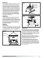
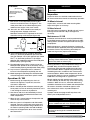
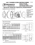
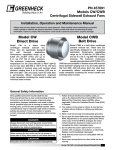
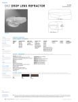
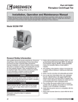
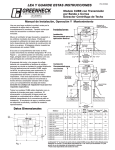
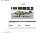
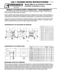
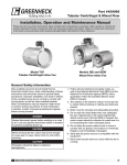
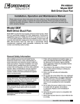
PN 471558
Downblast Centrifugal Roof Exhaust Fans
®
Installation, Operation and Maintenance Manual
Please read and save these instructions. Read carefully before attempting to assemble, install, operate or maintain the
product described. Protect yourself and others by observing all safety information. Failure to comply with instructions
could result in personal injury and/or property damage! Retain instructions for future reference.
Model G
Direct Drive
Model G is a direct drive downblast
centrifugal exhaust fan. These
fans are specifically designed
for roof mounted applications
exhausting relatively clean air.
Performance capabilities range
up to 4,300 cfm (7,305 m3/hr) and
up to 1 in. wg (249 Pa) of static
pressure. The maximum continuous
operating temperature is 180°F
(82ºC). G
models are available
in 27 sizes with nominal wheel
diameter ranging from 8 to 24 inches (203 to 610 mm)
(060 - 243 unit sizes). Each fan shall bear a permanently
affixed manufacturer’s engraved metal nameplate
containing the model number and individual serial
number. All fans are UL/cUL listed Standard 705.
Model GB
Belt Drive
GB Model Fans are belt drive
downblast centrifugal exhaust fans.
These fans are specifically designed
for roof mounted applications
exhausting relatively clean air.
Performance capabilities range up
to 44,700 cfm (75,950 m3/hr) and
up to 2.5 in. wg (623 Pa) of static
pressure. The maximum continuous
operating temperature is 180°F
(82ºC). GB models are available in
twenty sizes with nominal wheel
diameters ranging from 11 to 54 inches (279 to 1372 mm)
(071-540 unit sizes). Each fan shall bear a permanently
affixed manufacturer’s nameplate containing the model
number and individual serial number. All fans are
UL/cUL listed Standard 705.
General Safety Information
Only qualified personnel should install this fan. Personnel
should have a clear understanding of these instructions
and should be aware of general safety precautions.
Improper installation can result in electric shock, possible
injury due to coming in contact with moving parts, as
well as other potential hazards. Other considerations
may be required if high winds or seismic activity are
present. If more information is needed, contact a licensed
professional engineer before moving forward.
DANGER
Always disconnect, lock and tag power source before
installing or servicing. Failure to disconnect power
source can result in fire, shock or serious injury.
CAUTION
When servicing the fan, motor may be hot enough
to cause pain or injury. Allow motor to cool before
servicing.
CAUTION
Precaution should be taken in explosive atmospheres.
1
Model G/GB Centrifugal Roof Exhaust Fans
1. Follow all local electrical and safety codes, as well as
the National Electrical Code (NEC) and the National
Fire Protection Agency (NFPA), where applicable.
Follow the Canadian Electric Code (CEC) in Canada.
2. The rotation of the wheel is critical. It must be
free to rotate without striking or rubbing any
stationary objects.
3. Motor must be securely and adequately grounded.
4. Do not spin fan wheel faster than max cataloged fan
RPM. Adjustments to fan speed significantly affects
motor load. If the fan RPM is changed, the motor
current should be checked to make sure it is not
exceeding the motor nameplate amps.
5. Do not allow the power cable to kink or come in
contact with oil, grease, hot surfaces or chemicals.
Replace cord immediately if damaged.
6. Verify that the power source is compatible with
the equipment.
7. Never open access doors to a duct while the fan
is running.
Receiving
Upon receiving the product, check to make sure all items
are accounted for by referencing the bill of lading to
ensure all items were received. Inspect each crate for
shipping damage before accepting delivery. Notify the
carrier if any damage is noticed. The carrier will make
notification on the delivery receipt acknowledging any
damage to the product. All damage should be noted on
all the copies of the bill of lading which is countersigned
by the delivering carrier. A Carrier Inspection Report
should be filled out by the carrier upon arrival and
reported to the Traffic Department. If damaged upon
arrival, file a claim with carrier. Any physical damage
to the unit after acceptance is not the responsibility
of Greenheck Fan Corporation.
Unpacking
Figure 2
Hook With
Safety Latch
(Supplied by others)
(2) Bearing Plate
Lifting Points
(4) Drive Frame
Lifting Points
Figure 3
Verify that all required parts and the correct quantity
of each item have been received. If any items are
missing, report shortages to your local representative to
arrange for obtaining missing parts. Sometimes it is not
possible that all items for the unit be shipped together
due to availability of transportation and truck space.
Confirmation of shipment(s) must be limited to only
items on the bill of lading.
Screws
Screws
1¾ in.
(44 mm)
Handling
G Direct Drive
Curb Cap
Lift unit on to the roof utilizing hooks under the lip of the
shroud. Evenly space the hooks around the shroud using
a minimum of four lifting straps. Use a spreader bar to
ensure the straps do not come in contact with the unit
(see Figure 1).
Figure 1
Spreader Bar
Hook
Model G/GB Centrifugal Roof Exhaust Fans
When lifting the unit on to the roof, use either the four
lifting points on the drive frame or the two lifting points
on the bearing plate if present (see Figure 2 for lifting
points). Access to the drive frame is accomplished by
removing the screws pointed out in Figure 3. The cover
can then be removed and placed on a flat surface in an
area protected from strong winds.
When G/GB unit is on the roof, move fan to desired
location using lifting points and fasten securely through
mounting holes in base. Shims may be necessary
depending upon roofing material thickness.
Lifting Strap
2
GB Belt Drive
The motor amperage and voltage ratings must be
checked for compatibility to supply voltage prior to
final electrical connection. For G/GB installations, the
electrical supply should be routed through the conduit
chase located between the curb cap and the bottom of
the motor compartment. Wiring must conform to local
and national codes.
®
Storage
Fans are protected against damage during shipment. If
the unit cannot be installed and operated immediately,
precautions need to be taken to prevent deterioration of
the unit during storage. The user assumes responsibility
of the fan and accessories while in storage. The
manufacturer will not be responsible for damage during
storage. These suggestions are provided solely as a
convenience to the user.
Indoor
The ideal environment for the storage of fans and
accessories is indoors, above grade, in a low humidity
atmosphere which is sealed to prevent the entry of
blowing dust, rain or snow. Temperatures should be
evenly maintained between 30° to 110°F (-1° to 43°C)
(wide temperature swings may cause condensation
and “sweating” of metal parts). All accessories must be
stored indoors in a clean, dry atmosphere.
Remove any accumulations of dirt, water, ice or snow
and wipe dry before moving to indoor storage. To avoid
“sweating” of metal parts, allow cold parts to reach room
temperature. To dry parts and packages, use a portable
electric heater to get rid of any moisture buildup. Leave
coverings loose to permit air circulation and to allow for
periodic inspection.
The unit should be stored at least 3½ inches (89 mm)
off the floor on wooden blocks covered with moisture
proof paper or polyethylene sheathing. Aisles between
parts and along all walls should be provided to permit air
circulation and space for inspection.
Inspection and Maintenance
During Storage
While in storage, inspect fans once per month. Keep a
record of inspection and maintenance performed.
If moisture or dirt accumulations are found on parts,
the source should be located and eliminated. At each
inspection, rotate the wheel by hand ten to fifteen
revolutions to distribute lubricant on motor. If paint
deterioration begins, consideration should be given to
touch-up or repainting. Fans with special coatings may
require special techniques for touch-up or repair.
Machined parts coated with rust preventive should be
restored to good condition promptly if signs of rust
occur. Immediately remove the original rust preventive
coating with petroleum solvent and clean with lint-free
cloths. Polish any remaining rust from surface with
crocus cloth or fine emery paper and oil. Do not destroy
the continuity of the surfaces. Thoroughly wipe clean
with Tectyl® 506 (Ashland Inc.) or the equivalent.
For hard to reach internal surfaces or for occasional
use, consider using Tectyl® 511M Rust Preventive,
WD-40® or the equivalent.
Removing From Storage
As fans are removed from storage to be installed in their
final location, they should be protected and maintained
in a similar fashion until the fan equipment goes into
operation.
Outdoor
Fans designed for outdoor applications may be stored
outdoors, if absolutely necessary. Roads or aisles for
portable cranes and hauling equipment are needed.
The fan should be placed on a level surface to prevent
water from leaking into the fan. The fan should be
elevated on an adequate number of wooden blocks so
that it is above water and snow levels and has enough
blocking to prevent it from settling into soft ground.
Locate parts far enough apart to permit air circulation,
sunlight and space for periodic inspection. To minimize
water accumulation, place all fan parts on blocking
supports so that rain water will run off.
Do not cover parts with plastic film or tarps as these
cause condensation of moisture from the air passing
through heating and cooling cycles.
Fan wheels should be blocked to prevent spinning
caused by strong winds.
®
Model G/GB Centrifugal Roof Exhaust Fans
3
WARNING
Installation, troubleshooting and parts replacement is
to be performed only by qualified personnel.
WARNING
Disconnect power before installing or servicing.
CAUTION
A fan manufactured with an explosion resistant motor
does not certify the entire unit to be explosion proof.
Installation
Typical Roof Mounting Installation
1. On the roof surface, cut an appropriate sized hole
and follow manufacturer’s instructions on curb
installation. Caulk and flash the curb to ensure a
water tight seal.
2. If unit is equipped with a backdraft damper, it should
be installed now.
3. Remove motor cover. Access to the motor
compartment is accomplished by removing the
screws as shown in Figure 3.
4. Only on GB Belt Drive fans. On the drive frame use
the lifting lugs to lift and place the unit on top of roof
curb. (Refer to Figure 2 on page 2).
5. Secure fan to curb using a minimum of eight lag
screws, metal screws or the suitable fasteners.
Shims may be required depending upon curb
installation and roofing material.
Note: Severe duty applications may require
additional fasteners.
6. Verify power line wiring is de-energized before
connecting fan motor to power source.
7. Connect power supply wiring to the motor as
indicated on the motor nameplate or terminal box
cover. Check the power source for compatibility with
the requirements of your equipment.
8. Check fan wheel for free rotation, re-center
if necessary.
9. Check all fasteners for tightness.
10. Mount and wire safety disconnect switch under
motor cover. Wire control switches at ground level,
refer to Figure 4.
11. Replace motor cover.
Typical Wiring Diagram
MOTOR
MOTOR
SUPPLY VOLTAGE
115/208-230/60/1
J-BOX
SUPPLY VOLTAGE
208-230/460/60/3
J-BOX
L1
L2
L1
L3
L2
Figure 4
Vari-Green Wiring
For Vari-Green wiring refer to the Vari-Green
Motor IOM PN 473681 for complete wiring and
operation instructions.
4
Model G/GB Centrifugal Roof Exhaust Fans
®
G - Direct Drive
Curb
Cap
G 060, 065, 070, 075
G Direct Drive
Damper
Roof
Opening
*Approx.
Weight
17 (432)
8 (203)
10½ (267)
18 (8)
G 080, 085, 090, 095
17 (432)
10 (254)
12½ (267)
26 (12)
G 97, 98, 99
19 (483)
12 (305)
14½ (368)
57 (26)
G 103, 103 HP
19 (483)
12 (305)
14½ (368)
62 (28)
G 123
19 (483)
12 (305)
14½ (368)
65 (30)
G 133
19 (483)
12 (305)
14½ (368)
66 (30)
G 143, 143 HP
22 (559)
16 (406)
18½ (470)
76 (35)
G 163, 163 HP
22 (559)
16 (406)
18½ (470)
80 (36)
G 183, 183 HP
30 (762)
18 (457)
20½ (521)
119 (54)
G 203, 203 HP
30 (762)
18 (457)
20½ (521)
130 (59)
G 223/243, 223/243 HP
34 (864)
24 (610)
26½ (673)
150 (68)
Model
GB - Belt Drive
Figure 5 - Typical Roof Mounting Installation
Disconnect
Screws
¾ in.
Wiring by Others
8 or 12 in.
(203 or 305)
(19)
Damper
1¼ in.
(32)
*Dimensions shown
in inches (mm)
Recommended Duct
and Damper Size
1¼ in.
(32)
Recommended Roof
Opening
Curb
Cap
Damper
Roof
Opening
*Approx.
Weight
GB 071, 081, 091
19 (483)
12 (305)
14½ (368)
58 (26)
GB 101, 101HP
19 (483)
12 (305)
14½ (368)
63 (29)
GB Belt Drive
Figure 6 - Typical Roof Mounting Installation
Model
GB 121
19 (483)
12 (305)
14½ (368)
66 (30)
GB 131
19 (483)
12 (305)
14½ (368)
67 (30)
GB 141, 141HP
22 (559)
16 (406)
18½ (470)
83 (38)
GB 161, 161HP
22 (559)
16 (406)
18½ (470)
89 (40)
GB 180, 180HP
30 (762)
18 (457)
20½ (521)
125 (57)
GB 200, 200HP
30 (762)
18 (457)
20½ (521)
138 (63)
GB 220, 220HP,
240, 240HP
34 (864)
24 (610)
26½ (673)
158 (72)
GB 260
40 (1016)
30 (762)
32½ (826)
305 (138)
GB 300, 300HP
40 (1016)
30 (762)
32½ (826)
320 (145)
GB 330
46 (1168)
36 (914)
38½ (978)
385 (175)
GB 360, 360HP
46 (1168)
36 (914)
38½ (978)
403 (183)
GB 420
52 (1321) 42 (1067) 44½ (1130) 495 (225)
GB 480
52 (1321) 48 (1219) 50½ (1283) 623 (283)
GB 500
64 (1626) 54 (1372) 56½ (1435) 687 (312)
GB 540
64 (1626)
Disconnect
¾ in.
Wiring by Others
8 or 12 in.
(203 or 305)
(19)
Damper
1¼ in.
(32)
Dimensions shown
in inches (mm)
Recommended Duct
and Damper Size
1¼ in.
(32)
Recommended Roof
Opening
54 (1372) 56½ (1435) 748 (339)
• All dimensions are in inches (millimeters). *Approximate weight shown in pounds
(kilograms) is the largest cataloged Open Drip Proof motor.
• The roof curb should be 1½ in. (38 mm) less than the curb cap to allow for roofing
and flashing.
®
Model G/GB Centrifugal Roof Exhaust Fans
5
Pre-Starting Checks
Wheel Rotation
1. Check all fasteners and set screws for tightness. The
wheel should rotate freely and be aligned as shown
in Figure 7 below.
Clockwise
Rotation
All Models
2. Wheel position is preset and the unit is test run at the
factory. Movement may occur during shipment and
realignment may be necessary.
3. Only G unit - Centering height alignment can be
accomplished by loosening the set screws in the
wheel and moving the wheel to the desired position.
4. Only GB unit - Centering can be accomplished by
loosening the bolts holding the drive frame to the
shock mounts and repositioning the drive frame.
5. Only GB unit - Wheel and inlet cone overlap can be
adjusted by loosening the set screws in the wheel
and moving the wheel to the desired position.
6. Only GB unit - Fan RPM should be checked and
verified with a tachometer.
7. Check wheel rotation (viewing from the shaft side)
by momentarily energizing the unit. Rotation should
be clockwise as shown in Figure 8 and correspond
to rotation decal on the unit. If wheel rotation is
incorrect, reverse two of the wiring leads or check
motor wiring for single phase.
Wheel Overlap and Gap Dimensions
Model
G - Overlap in. (mm)
H - Gap in. (mm)
⁄32 (2)
G
060-095
G
97-163
1
⁄4 (6)
–
GB
071-161
1
⁄4 (6)
–
183-243
3
GB
180-240
3
GB
260-540
1
G
–
3
⁄8 (10)
–
⁄8 (10)
–
⁄2 (13)
–
Counterclockwise
Airflow
Figure 8
Clockwise
WARNING
Airflow
Correct direction of wheel rotation is critical. Reversed
rotation will result in poor air performance, motor
overloading and possible burnout.
WARNING
The fan has been checked for mechanical noises at the
factory prior to shipment. If mechanical noise should
develop, suggested corrective actions are offered in
the Troubleshooting section.
IMPORTANT
Over tightening will cause excessive bearing wear and
noise. Too little tension will cause slippage at startup
and uneven wear.
Model GB
Pre-Starting Belt Tension Checks
8. Always loosen tension enough to install belts without
stretching, see Figure 9.
Belts
Figure 9
G
H
Figure 7
Do not force belt(s). Forcing the
belt(s) will break the cords and
cause belt failure
.
9. For units with two groove pulleys, adjust so the
tension is equal in both belts.
10. If adjustments are made, it is very important to check
the pulleys for proper alignment. Misaligned pulleys
lead to excessive belt wear vibration, noise and
power loss, see Figure 10.
Figure 10
6
Model G/GB Centrifugal Roof Exhaust Fans
®
IMPORTANT
Fasteners
(4) *Fasteners
Adjust (tighten) belt tension after the first 24-48 hours
of operation.
*Identical fasteners on
opposing side must also
be loosened.
Inspection
Inspection of the fan should be conducted at the first
30 minute and 24 hour intervals of satisfactory operation.
Figure 11
11. Belt tension can be adjusted by loosening four
fasteners on the drive frame, see Figure 11. The
motor plate slides on the slotted adjusting arms
and drive frame angles in the same manner.
12a. Sizes 071-161: Belts should be tensioned just
enough to prevent slippage at full load.
Note: Belts should have a slight bow on the slack
side while running at full load (see Figure 12a).
Deflection
30 Minute Interval
Inspect bolts, setscrews and motor mounting bolts.
Adjust and tighten as necessary.
24 Hour Interval
Check all internal components. On GB unit only, inspect
belt alignment and tension. Adjust and tighten as
necessary.
Maintenance: G / GB
Installation and maintenance are to be performed only
by qualified personnel who are familiar with local codes
and regulations and who are experienced with this type
of equipment.
Slack
Side
Figure 12a
Figure 12b
12b. Sizes 180-540: Belt tension should be adjusted to
allow 1⁄64 in. (0.397 mm) of deflection per inch of belt
span. For example, a 15 in. (381 mm) belt span should
have 15⁄64 in. (0.234 mm) (or about 1⁄4 in. (6 mm)) of
deflection with moderate thumb pressure at mid-point
between pulleys (see Figure 12b).
13. The adjustable motor pulley is factory set for the
RPM specified. Speed can be increased by closing
or decreased by opening the adjustable motor pulley.
14. Any increase in speed represents a substantial
increase in the horsepower required by the unit.
15. Motor amperage should always be checked to avoid
serious damage to the motor when speed is varied.
Operation: G / GB
Motor maintenance is generally limited to cleaning and
lubrication (where applicable). Cleaning should be limited
to exterior surfaces only. Removing dust buildup on
motor housing ensures proper motor cooling.
WARNING
Always disconnect, lock and tag power source before
servicing. Failure to disconnect power source can
result in fire, shock or serious injury.
Greasing of motors is only intended when fittings are
provided. Many fractional horsepower motors are
permanently lubricated and should not be lubricated
after installation. Motors supplied with grease fittings
should be greased in accordance with manufacturers’
recommendations. Where motor temperatures do not
exceed 104ºF (40ºC), the grease should be replaced after
2,000 hours of running time as a general rule.
1. Before starting up or operating fan, check all
fasteners for tightness. In particular, check the
setscrews in wheel hub.
Wheels require very little attention when moving clean
air. Occasionally, oil and dust may accumulate causing
imbalance. When this occurs, the wheel and housing
should be cleaned to ensure smooth and safe operation.
2. While in the OFF position or before connecting the
fan to power, turn the fan wheel by hand to be sure it
is not striking the venturi or any obstacle.
All fasteners should be checked for tightness each
time maintenance checks are performed prior to
restarting unit.
3. Start the fan and shut it off immediately to check
rotation of the wheel with directional arrow in the
motor compartment.
A proper maintenance program will help these units
deliver years of dependable service.
4. When the fan is started, observe the operation and
check for any unusual noises.
5. With the system in full operation and all ductwork
attached, measure current input to the motor and
compare with the nameplate rating to determine if
the motor is operating under safe load conditions.
6. Keep inlets and approaches to fan clean and free
from obstruction.
®
CAUTION
Uneven cleaning of the wheel will produce an out of
balance condition that will cause vibration in the fan.
WARNING
This unit should be made non-functional when cleaning
the wheel or housing (fuses removed, disconnect
locked off).
Model G/GB Centrifugal Roof Exhaust Fans
7
Belt/Bearing Maintenance GB Unit
1. Belts tend to stretch after a period of time.
They should be checked periodically for wear and
tightness. When replacing belts, use the same type
as supplied with the unit.
11. During the first few months of operation, check
bearing setscrews periodically to ensure tightness.
12. If unit is to be left idle for an extended period,
remove belts and store in a cool, dry place to avoid
premature belt failure.
2. Matched belts should always be used on units with
multi-groove pulleys.
Recommended Relubrication
Frequency in Months
3. For belt replacement, loosen the tensioning device
enough to allow removal of the belt by hand.
NOTE: If unusual environment conditions exist (extreme
temperature, moisture or contaminants) more frequent
lubrication is required.
4. Once installed, adjust belts as shown in
“Pre‑Starting Checks.”
5. Shaft bearings can be classified in two
groups: relubricating and non-relubricating. All
non‑relubricating bearings on model GB fans are
factory lubricated and require no further lubrication
under normal use (between -20º to 180ºF (-29º to 82ºC)
in a relatively clean environment).
6. On GB belt driven fans, the standard cast pillow
block bearings are factory lubricated and are
provided with external grease fittings. Annual
lubrication is recommended, or more frequently
if needed (See Table 2). Do not over-grease. Use
only one or two shots of lubricant with a hand gun.
Maximum hand gun rating is 40 psi. Rotate bearings
during lubrication where good safety practice
permits. Caution should be employed to prevent over
packing or contamination.
7. Grease fittings should be wiped clean. The unit
should be in operation while lubricating. Extreme
care should be used around moving parts.
8. Grease should be pumped in very slowly until a slight
bead forms around the seal. A high grade lithium
base grease should be used. (See Table 3)
9. To ensure tightness, check pulley setscrews. Proper
keys must be in keyways.
10. Fan RPM should not be readjusted. Only use pulleys
of identical size and type when replacing pulleys.
A good quality lithium base grease, conforming to
NLGI Grade 2 consistency, such as those listed here
may be used.
Table 2: Suggested Fan Bearing Greasing Intervals
Interval
(months)
Type of Service
1 to 3
Heavy duty in dirty, dusty locations; high ambient
temperatures; moisture laden atmosphere; vibration.
3 to 6
12 to 24 hours per day, heavy duty, or if moisture is
present
6 to 12
8 to 16 hours per day in clean, relatively dry
atmosphere
12 to 18
Infrequent operation or light duty in clean
atmosphere
Table 3: Grease Manufacturers
Manufacturer
Grease (NLGI #2)
U.S. Electric Motors
Grease No. 83343
Chevron U.S.A. Inc
Chevron SRI Grease #2
Mobilith
Mobil 532
Premium BRB #2
Texaco Multifak #2
Poor
Rykon Premium #2
Unirex N2
B Shell Alvania #2
Mobil Oil Corporation
Texaco, Inc.
Poor
Amoco Oil Co.
Exxon
Shell
Good
Fan Inlet Connections
In order to assure proper fan performance, caution must be exercised in fan placement and connection to the
ventilation system. Obstructions, transitions, poorly designed elbows, improperly selected dampers, etc. can
cause reduced performance, excessive noise and increased mechanical stress. For performance to be as
published, the system must provide uniform and stable airflow into the fan.
Good
Poor
Dampers must open fully.
Use motorized dampers
in low airflow applications
to reduce losses.
8
Poor
Avoid sharp turns or
entrance conditions which
cause uneven flow. Use
turning
vanes in elbows to
Good
reduce adverse effects.
Model G/GB Centrifugal Roof Exhaust Fans
Good
Provide uniform airflow
at fan inlet to assure
optimum performance.
Provide uniform airflow at fan inlet and through
the damper to assure optimum performance.
The curb cap should be three wheel diameters
from the radius. Use turning vanes in duct
when possible.
®
Troubleshooting
WARNING: Before taking any corrective action, make certain unit is not capable of operation during repairs.
PROBLEM
Excessive noise
or vibration
High horsepower
Fan does
not operate
Motor overloads
or overheats
Reduced airflow
®
CAUSE
CORRECTIVE ACTION
Wheel rubbing inlet
Adjust wheel and/or inlet cone. Tighten wheel hub or bearing collars
on shaft.
V-belt drive
Tighten pulleys on motor/fan shaft. Adjust belt tension. Align pulleys
properly, see page 6, Figure 9-10. Replace worn belts or pulleys.
Bearings
Replace defective bearing(s). Lubricate bearings. Tighten collars
and fasteners.
Wheel unbalance
Clean all dirt off wheel. Check wheel balance, rebalance in place if
necessary.
Belts too tight or too loose
Adjust tension, see page 7, Figure 12a-b.
Wheel improperly aligned and
rubbing
Center wheel on inlet, see page 6, Figure 7.
Loose drive or motor pulleys
Align and tighten. See “Pre-Starting Checks”, see page 6.
Foreign objects in wheel or housing
Remove objects, check for damage or unbalance.
Fan base not securely anchored
Secure properly.
Motor hood loose and rattling
Tighten screws securing motor hood.
Defective or loose motor bearings
Replace motor with same frame size, RPM-HP.
Fan
Check rotation of wheel, see page 6, Figure 8. Reduce fan speed.
Duct system
Resize ductwork. Check proper operation of face and bypass dampers.
Check filters and access doors.
Electrical supply
Check fuses/circuit breakers. Check for switches off. Check for correct
supply voltage.
Drive
Check for broken belts. Tighten loose pulleys.
Motor
Assure motor is correct horsepower and not tripping overload protector.
Lubrication
Check for excessive or insufficient grease in the bearing.
Mechanical
Replace damaged bearing. Relieve excessive
belt tension. Align bearings. Check for bent shaft.
Belt slippage
Adjust tension or replace bad belts, see page 6-7.
Over/Under line voltage
Contact power company.
Incorrect wheel rotation
Check motor wiring (page 4) verify motor is wired for correct rotation.
Wheel RPM too high
Check drives or slow down fan by opening variable pitch pulley on
motor shaft.
Undersized motor
Check motor ratings with catalog speed and air capacity chart.
Motor wired incorrectly
Check motor wiring to wiring diagram located on fan motor.
System resistance too high
Check system: Proper operation of backdraft or control dampers,
obstruction in ductwork, clean dirty filters.
Unit running backwards
Correct as shown on page 6, Figure 8.
Excessive dirt buildup on wheels
Clean wheel.
Improper wheel alignment
Center wheel on inlets, see Pre-Starting checks on page 6, Figure 7.
Dampers closed
Inspect and repair.
Blocked duct/clogged filter
Clean or replace.
Belt slippage
Replace and adjust tension.
Speed too slow
Check for correct drives.
Model G/GB Centrifugal Roof Exhaust Fans
9
Maintenance Documentation
Job Information
Job Name:___________________________________ Service Organization:__________________________________
Address:____________________________________Address:______________________________________________
City:________________________________________City:__________________________________________________
State:_______________ Zip:___________________State:________________ Zip:___________________________
Phone:______________________________________Phone:_______________________________________________
Contact Person:______________________________ Work Done By:________________________________________
Nameplate Information
Field Start-Up Documentation
Model:______________________________________
Volts:_________ Hertz:_________ Phase:_______ Actual Voltage:________ Hertz:_______ Phase:__________
Amps:_______________ Mark:_________________ Actual Amperage:_____________________________________
Supply hp:___________ Exhaust hp:___________ Blower Rotation:______________________________________
Serial Number:_______________________________ Air Volume: Design cfm:______________________________
Model Voltage:_______________________________
Actual cfm:_______________________________
Motor Amperage:____________________________ Level of fan (L or H):___________________________________
Fan RPM:____________________________________ Fan RPM Range (min.)____________ (max.)______________
Maintenance Log
Date
Time
10 Model G/GB Centrifugal Roof Exhaust Fans
Notes
®
Parts List
G Direct Drive Centrifugal Roof Exhaust Fan
NOTE
Each fan bears a manufacturer’s nameplate with model number and serial
number embossed. This information will
assist the local Greenheck representative
and the factory in providing service and
replacement parts. Before taking any
corrective action, make certain unit is
not capable of operation during repairs.
Motor Cover
Motor
Shock
Mounts
Shroud
Birdguard
Wheel
Curb Cap/
Venturi
Hood Clip
Shroud Brace
Vertical
Support
Lower
Windband
GB Belt Drive Centrifugal Roof Exhaust Fan
Motor Cover
Shaft Pulley
Bearings
Drive Frame
Assembly
Shock Mounts
Belt
Motor Pulley
Motor
Fan Shaft
Shroud
Wheel
Birdguard
Shroud Brace
Conduit
Chase
Vertical
Support
®
Windband
Curb Cap/
Venturi
Model G/GB Centrifugal Roof Exhaust Fans 11
Roof Curb Installation
Warranty
Greenheck warrants this equipment to be free from defects in material and workmanship for a period of one year from
the shipment date. Any units or parts which prove defective during the warranty period will be replaced at our option
when returned to our factory, transportation prepaid. Motors are warranted by the motor manufacturer for a period of
one year. Should motors furnished by Greenheck prove defective during this period, they should be returned to the
nearest authorized motor service station. Greenheck will not be responsible for any removal or installation costs.
As a result of our commitment to continuous improvement, Greenheck reserves the right to change specifications
without notice.
Greenheck Catalog G/GB provides additional information
describing the equipment, fan performance, available
accessories, and specification data.
AMCA Publication 410-96, Safety Practices for Users and
Installers of Industrial and Commercial Fans, provides
additional safety information. This publication can be
obtained from AMCA International, Inc. at: www.amca.org.
®
Phone: (715) 359-6171 • Fax: (715) 355-2399 • E-mail: [email protected] • Website: www.greenheck.com
12 471558 • Model G/GB IOM, Rev. 3, October 2010
Copyright 2010 © Greenheck Fan Corp.