1
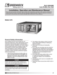
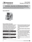
PN 453283
Series L: Models LB, LBP, LD, and LDP
Low Silhouette Centrifugal Roof Exhaust Fans
®
Installation, Operation and Maintenance Manual
Please read and save these instructions for future reference. Read carefully before attempting
to assemble, install, operate or maintain the product described. Protect yourself and others by
observing all safety information. Failure to comply with instructions could result in personal injury
and/or property damage!
Series L Exhaust Fans
Greenheck’s Series L, low silhouette, models LD, LB,
LDP, and LBP centrifugal roof exhaust fans provide the
industry’s best performance and durability for general clean
air applications. Series L exhaust fans have the broadest
performance in the industry, up to 1.25 in. wg (311 Pa) and
37,500 cfm (63,713 m3/hr).
The severe duty models LDP and LBP are far superior to
any centrifugal roof exhaust fan currently in the market.
Specifically designed for applications with extremely high
structural design load requirements. Designed with structural
steel supports and ESD-603D louver blades, the severe duty louver enclosure (SDLE) may be used in any
application which requires a fan to endure high winds with the potential of wind blown debris. Miami-Dade
notice of acceptance number 03-0422.05.
General Safety Information
Only qualified personnel should install this fan.
Personnel should have a clear understanding of
these instructions and should be aware of general
safety precautions. Improper installation can result
in electric shock, possible injury due to coming in
contact with moving parts, as well as other potential
hazards. Other considerations may be required
if high winds or seismic activity are present. If
more information is needed, contact a licensed
professional engineer before moving forward.
DANGER
Always disconnect, lock and tag power source before
installing or servicing. Failure to disconnect power source
can result in fire, shock or serious injury.
CAUTION
When servicing the fan, motor may be hot enough to
cause pain or injury. Allow motor to cool before servicing.
CAUTION
Precaution should be taken in explosive atmospheres.
1. Follow all local electrical and safety codes, as
well as the National Electrical Code (NEC) and
the National Fire Protection Agency (NFPA),
where applicable. Follow the Canadian Electric
Code (CEC) in Canada.
2. The rotation of the wheel is critical. It must be
free to rotate without striking or rubbing any
stationary objects.
3. Motor must be securely and adequately
grounded.
4. Do not spin fan wheel faster than max cataloged
fan RPM. Adjustments to fan speed significantly
effects motor load. If the fan RPM is changed,
the motor current should be checked to make
sure it is not exceeding the motor nameplate
amps.
5. Do not allow the power cable to kink or come
in contact with oil, grease, hot surfaces,
or chemicals. Replace cord immediately if
damaged.
6. Verify that the power source is compatible with
the equipment.
7. Never open access doors to a duct while the fan
is running.
Series L: Models LB, LBP, LD, and LDP
1
Receiving
Upon receiving the product, check to make sure
all items are accounted for by referencing the bill
of lading to ensure all items were received. Inspect
each crate for shipping damage before accepting
delivery. Notify the carrier if any damage is noticed.
The carrier will make notification on the delivery
receipt acknowledging any damage to the product.
All damage should be noted on all the copies of the
bill of lading which is countersigned by the delivering
carrier. A Carrier Inspection Report should be filled
out by the carrier upon arrival and reported to the
Traffic Department. If damaged upon arrival, file
a claim with carrier. Any physical damage to the
unit after acceptance is not the responsibility of
Greenheck Fan Corporation.
Unpacking
Verify that all required parts and the correct quantity
of each item have been received. If any items are
missing, report shortages to your local representative
to arrange for obtaining missing parts. Sometimes it
is not possible that all items for the unit be shipped
together due to availability of transportation and
truck space. Confirmation of shipment(s) must be
limited to only items on the bill of lading.
Handling
When lifting the unit to the roof, securely fasten
straps to the drive frame located in the motor
compartment. Access to the motor compartment is
accomplished by removing bolts securing the hood
to the base. The hood cover will need to be removed
for access to the drive frame. The cover can then
be removed and placed on a flat surface in an area
protected from strong winds.
When unit is on the roof, move fan to desired location
and fasten securely through mounting holes in base.
Shims may be necessary depending upon roof
material thickness.
The motor amperage and voltage ratings must be
checked for compatibility to supply voltage prior to
final electrical connection. Electrical lead-in wires
should be run through the conduit provided between
the curb and the bottom of the motor compartment.
Wiring must conform to local and national codes.
CAUTION
Do not lift by the fan hood. Avoid lifting fans in a
way that will bend or distort fan parts. Never pass
slings or timbers through the venturi of fan. Fans
with special coatings or paints must be protected
in handling to prevent damage.
Storage
Fans are protected against damage during shipment.
If the unit cannot be installed and operated
immediately, precautions need to be taken to prevent
deterioration of the unit during storage. The user
assumes responsibility of the fan and accessories
2
Series L: Models LB, LBP, LD, and LDP
while in storage. The manufacturer will not be
responsible for damage during storage. These
suggestions are provided solely as a convenience to
the user.
Indoor
The ideal environment for the storage of fans and
accessories is indoors, above grade, in a low
humidity atmosphere which is sealed to prevent the
entry of blowing dust, rain or snow. Temperatures
should be evenly maintained between 30° to 110°F
(-1° to 43°C), wide temperature swings may cause
condensation and “sweating” of metal parts. All
accessories must be stored indoors in a clean, dry
atmosphere.
Remove any accumulations of dirt, water, ice, or
snow and wipe dry before moving to indoor storage.
To avoid “sweating” of metal parts allow cold parts to
reach room temperature. To dry parts and packages
use a portable electric heater to remove any moisture
build up. Leave coverings loose to permit air
circulation and to allow for periodic inspection.
The unit should be stored at least 3½ inches (89 mm)
off the floor on wooden blocks covered with moisture
proof paper or polyethylene sheathing. Aisles
between parts and along all walls should be provided
to permit air circulation and space for inspection.
Outdoor
Fans designed for outdoor applications may be
stored outdoors, if absolutely necessary. Roads or
aisles for portable cranes and hauling equipment are
needed.
The fan should be placed on a level surface to
prevent water from leaking into the fan. The fan
should be elevated on an adequate number of
wooden blocks so it is above water and snow levels
and has enough blocking to prevent it from settling
into soft ground. Locate parts far enough apart to
permit air circulation, sunlight and space for periodic
inspection. To minimize water accumulation, place all
fan parts on blocking supports so rain water will run
off.
Do not cover parts with plastic film or tarps as these
cause condensation of moisture from the air passing
through heating and cooling cycles. Fan wheels
should be blocked to prevent spinning caused by
strong winds.
Inspection and Maintenance During
Storage
While in storage, inspect fans once per month. Keep
a record of inspection and maintenance performed.
If moisture or dirt accumulations are found on parts,
the source should be located and eliminated. At each
inspection, rotate the wheel by hand ten to fifteen
revolutions to distribute lubricant on motor. If paint
deterioration begins, consideration should be given
to touch-up or repainting. Fans with special coatings
may require special techniques for touch-up or
repair.
®
Machined parts coated with rust preventive should
be restored to good condition promptly if signs of
rust occur. Immediately remove the original rust
preventive coating with petroleum solvent and clean
with lint-free cloths. Polish any remaining rust from
surface with crocus cloth or fine emery paper and
oil. Do not destroy the continuity of the surfaces.
Thoroughly wipe clean with Tectyl® 506 (Ashland Inc.)
or the equivalent. For hard to reach internal surfaces
or for occasional use, consider using Tectyl® 511M
Rust Preventive, WD-40® or the equivalent.
Series L Dimensions
Model LB
Size
10
14
18
C
B
D
21
24
E
30
1.75
(44)
A
36
F
A
42
C
C
B
DD
48
B
54
Model LBP
1.75
1.75
(44)
(44)
1.75
(44)
1.75
(44)
1.75
1.75
(44)
(44)
CA
A
D
C
D
C
B
D
E
B
A
B
C
F
A
A
F
A
A
F
CA
A
C
D A
B
F
B
14
E
18
E
21
24
E
E
42
E
1.75
(44)
1.75
(44)
1.75
1.75
(44)
(44)
BB
A
DD
A
Model LD
A
B
A
D
B
D
C
E
F
F
C
A
C
A
E
E
F
E
1.75
(44)
1.75
(44)
B
A
BA
B
F
A
Model LDP
D
48
54
Size
B
22
39
C
D
E
28
171/4
17
Damper Roof Weight
Size Opening Galv.
31/4
12
141/2
56
F
(559) (991)
(711) (438) (432)
(85)
(305)
16
181/2
(368)
(25)
(660) (991)
(889) (445) (457) (102)
(406)
18
(470)
201/2
(37)
(762) (991) (1016) (445) (533) (114)
(457)
(521)
(762) (1295) (1092) (584) (584) (152)
(457)
(864) (1295) (1156) (521) (597) (171)
(610)
(1016) (1600) (1270) (749) (676) (216)
(762)
36
381/2
(1168) (1600) (1524) (686) (829) (248)
(914)
26
30
30
34
40
46
52
39
39
35
40
51
43
51
171/2
171/2
23
18
21
23
4
41/2
6
451/2 201/2 231/2 63/4
63
50
63
60
27
325⁄8
81/2
93/4
30
(521)
261/2
(673)
(61)
145
(66)
188
(85)
321/2
249
(826)
(113)
(978)
(153)
338
42
441/2
(1067)
(1130)
(180)
(1473) (2210) (1788) (1041) (1054) (295)
(1219)
(1283)
(195)
(1626) (2210) (2019) (965) (1153) (318)
(1372)
(1435)
(270)
64
70 ⁄8 331/2 37 ⁄8 111/2
24
201/2
135
(1321) (1905) (1794) (851) (949) (292)
58
75
291/2 265⁄8
18
81
5
87
703⁄8
87
791/2
A
B
22
381/2
(559) (978)
3
41
38
411/2 115⁄8
453⁄8 121/2
C
D
E
28
14
17
48
54
501/2
561/2
(660) (1016) (813) (406) (432) (660)
(406)
(762) (1168) (914) (483) (622) (762)
(457)
(762) (1168) (914) (483) (622) (762)
(457)
(864) (1257) (1016) (508) (597) (864)
(610)
30
321/2
(1016) (1473) (1168) (584) (673) (1016)
(762)
(1168) (1600) (1314) (660) (873) (1168)
30
30
34
32
46
36
46
36
19
241/2
30
18
(521)
201/2
(521)
(53)
179
(81)
191
(86)
36
381/2
(144)
(914)
(978)
(201)
(1321) (1791) (1473) (737) (972) (1321) (1067)
(1130)
(240)
(1473) (1943) (1626) (813) (1026) (1473) (1219)
(1283)
(263)
(1626) (2121) (1778) (889) (1108) (1626) (1372)
(1435)
(354)
52
58
64
A
63
513/4
701/2
58
761/2
64
831/2
70
B
C
26
29
32
35
D
261/2
343⁄8
381/4
403⁄8
435⁄8
E
40
46
52
58
64
F
24
(470)
201/2
(45)
116
(826)
23
34
18
(368)
181/2
(108)
46
231/2
30
16
(673)
58
20
241/2
26
239
46
40
19
17
261/2
40
491/2
16
596
Damper Roof Weight
Size Opening Alum.
325⁄8
12
141/2
99
(305)
40
430
F
(711) (356) (432) (829)
26
396
42
48
54
441/2
501/2
561/2
318
444
530
579
780
Damper Roof Weight
Size Opening Galv.
60- 17
22
27 131/2 13
2
75 (432) (559) (686) (343) (330) (51)
8
101/2
37
(203)
(267)
(17)
80- 19
28
27 131/2 16
4
95 (483) (711) (686) (343) (406) (102)
10
121/2
45
(254)
(318)
(20)
100- 22
30
27 131/2 18
4
120 (559) (762) (686) (343) (457) (102)
12
141/2
57
(305)
(368)
(26)
E
F
A
A
1.75
(44)
C
D
30
36
F
D
C
Size
10
F
B
D
E
A
E
C
A
C
D
Size
A
B
C
D
E
6075
17
23
111/2 131/2
(432
(584)
(292) (343)
80- 19
95 (483)
25
121/2 161/2
(635)
(318) (419)
100- 22
120 (559)
(711)
F
—
Damper Roof Weight
Size Opening Alum.
8
101/2
49
(203)
(267)
(22)
E
1.75
(44)
1.75
(44)
E
A
A
A
A
28
14
181/2
(356) (470)
—
—
10
121/2
63
(254)
(318)
(29)
12
141/2
82
(305)
(368)
(37)
All dimensions given in inches (millimeters). Weights given in pounds (kilograms).
®
Series L: Models LB, LBP, LD, and LDP
3
G
Removing From Storage
As fans are removed from storage to be installed
in their final location, they should be protected
and maintained in a similar fashion until the fan
equipment goes into operation.
Pre-Starting Belt Tension Checks
6. Always loosen tension enough to install belt
without stretching, see Figure 3.
BELTS
Pre-Startup Checks
1. Check all fasteners for tightness. The wheel
should rotate freely and be aligned as shown in
Figure 1.
WHEEL OVERLAP AND GAP DIMENSIONS
Model
G - Overlap in. (mm)
LD/LDP 60-095
–
LD/LDP 100-120
–
LB/LBP 10-14
H - Gap in. (mm)
⁄32 (2)
3
⁄4 (6)
1
1
⁄4 (6)
–
⁄8 (10)
–
⁄2 (13)
–
LB/LBP 18-24
3
LB/LBP 30-54
1
G
Do not force belt(s). Forcing the
belt(s) will break the cords and
cause belt failure
Figure 3
7. If adjustments are made, it is very important
.
to check the pulleys for proper alignment.
Misaligned pulleys lead to excessive belt wear
vibration, noise and power loss, see Figure 4.
H
Figure 4
Figure 1
2. Wheel position is preset and the unit is test
run at the factory. Movement may occur during
shipment, and realignment may be necessary.
3. Centering can be accomplished by loosening
the bolts holding the drive frame to the shock
mounts and repositioning the drive frame.
4. Wheel and inlet cone overlap can be adjusted
by loosening the setscrews in the wheel and
moving the wheel to the desired position.
5. Check wheel rotation by momentarily energizing
the unit. Rotation should be clockwise as shown
in Figure 2 and correspond to the rotation decal
on the unit. Rotation is determined when the unit
is viewed from the motor or shaft pulley side.
Wheel Rotation
All Series L fans have
clockwise (CW) wheel
rotation when viewed
from top of fan.
Figure 2
FASTENERS
*Identical fasteners on
opposing side must
also be loosened.
R
Figure 5
9. Belt tension should be adjusted to allow 1⁄64 in.
(0.397 mm) of deflection per inch of belt span.
For example, a 15 in. (381 mm) belt span should
have 15⁄64 in. (0.234 mm) (or about 1⁄4 in. (6 mm))
of deflection with moderate thumb pressure at
mid-point between pulleys, see Figure 6.
WARNING
C l o c k wi s e
WARNING
Correct direction of wheel rotation is critical.
WRONG
WRONG
Reversed rotation
will result in poor air
performance, motor overloading and possible
motor burnout.
WRONG
4
8. Belt tension can be adjusted by loosening four
fasteners (marked “R” in Figure 5) on the drive
frame. This allows the motor plate to slide on the
drive frame angles for proper positioning.
Series L: Models LB, LBP, LD, and LDP
The fan has been checked for mechanical noises at
the factory prior to shipment. If mechanical noise
should develop, suggested corrective actions are
offered in the Troubleshooting section.
WARNING
Over tightening will cause excessive bearing wear
and noise. Too little tension will cause slippage at
startup and uneven wear.
®
WARNING
Always disconnect, lock and tag power source before
servicing. Failure to disconnect power source can
result in fire, shock or serious injury.
Deflection=
Belt Span
64
WARNING
Belt Span
Uneven cleaning of the wheel will produce an out of
balance condition that will cause vibration in the fan.
WARNING
This unit should be made non-functional when
cleaning the wheel or housing (fuses removed,
disconnect locked off).
Figure 6
Belt/Bearing Maintenance
10. The adjustable motor pulley is factory set for
the RPM specified. Speed can be increased by
closing or decreased by opening the adjustable
motor sheave.
11. Two groove variable pitch pulleys must be
adjusted an equal number of turns open or
closed.
12. Any increase in speed represents a substantial
increase in the horsepower required by a unit.
13. Motor amperage should always be checked to
avoid serious damage to the motor when speed
is varied.
IMPORTANT
Adjust (tighten) belt tension after the first
24-48 hours of operation.
Maintenance
Motor maintenance is generally limited to cleaning
and lubrication (where applicable). Cleaning should
be limited to exterior surfaces only. Removing dust
buildup on motor housing ensures proper motor
cooling.
Greasing of motors is only intended when fittings
are provided. Many fractional hp motors are
permanently lubricated and should not be lubricated
further. Motors supplied with grease fittings should
be greased in accordance with manufacturers’
recommendations. Where motor temperatures do not
exceed 104ºF (40ºC), the grease should be replaced
after 2000 hours of running time as a general rule.
Wheels require very little attention when moving
clean air. Occasionally, oil and dust may accumulate
causing imbalance. When this occurs, the wheel and
housing should be cleaned to ensure smooth and
safe operation.
All fasteners should be checked for tightness each
time maintenance checks are performed prior to
restarting unit.
A proper maintenance program will help these units
deliver years of dependable service.
®
1. Belts tend to stretch after a period of time. They
should be checked periodically for wear and
tightness. When replacing belts, use the same
type as supplied with the unit.
2. Matched belts should always be used on units
with multi-groove pulleys.
3. For belt replacement, loosen the tensioning
device far enough to allow removal of the belt
by hand. Do not force belts on or off. This may
cause cords to break, leading to premature belt
failure.
4. Once installed, adjust belts as shown in “PreStarting Checks.”
5. Shaft bearings can be classified in two groups:
relubricating and non-relubricating. All bearings
are factory lubricated and require no further
lubrication under normal use (between -20ºF
and 180ºF (-29° to 82°C) in a relatively clean
environment).
6. Units installed in hot, humid or dirty locations
should be equipped with special bearings.
These bearings will require frequent lubrication.
Caution should be employed to prevent
overpacking or contamination.
7. Grease fittings should be wiped clean. The
unit should be in operation while lubricating.
Extreme care should be used around moving
parts.
8. Grease should be pumped in very slowly until a
slight bead forms around the seal. A high-grade
lithium base grease is recommended.
9. Direct drive units require little maintenance
except for cleaning, wheel alignment, and oiling
according to motor label instructions.
Series L: Models LB, LBP, LD, and LDP
5
Parts List
NOTE: Each fan bears a manufacturer’s nameplate with model number and serial number embossed. This information
will assist the local Greenheck representative and the factory in providing service and replacement parts. Before taking
any corrective action, make certain unit is not capable of operation during repairs.
CAUTION: A fan manufactured with an explosion-resistant motor does not certify the entire unit to be explosion proof.
Refer to UL Listing Mark for the fans approved usage.
FABRA HOOD STYLE
FAN SHAFT
DRIVE
ASSEMBLY
VIBRATION
ISOLATORS
BIRDSCREEN
HINGED
ACCESS
WINDBAND
MOTOR
CURB CAP
WHEEL
DRIVE
FRAME
HOOD COVER
BIRDSCREEN
MOTOR
FAN
SHAFT
DRIVE
ASSEMBLY
DRIVE
FRAME
LOUVERED
PENTHOUSE
WHEEL
6
Series L: Models LB, LBP, LD, and LDP
®
Troubleshooting
WARNING: Before taking any corrective action, make certain unit is not capable of operation during repairs.
PROBLEM
Reduced Airflow
Excessive Noise
or Vibration
CAUSE
CORRECTIVE ACTION
System resistance too high
Check system for proper operation of backdraft or
control dampers; remove obstructions in ductwork, etc.
Unit running backwards
See Pre-Starting Checks.
Fan speed too low
Increase fan speed.
Excessive dirt buildup on
wheel
Clean wheel.
Improper wheel alignment
Center wheel on inlets.
Bad Bearings
Replace.
Belts too tight or too loose
Refer to Figure 4 and adjust tension.
Wheel improperly aligned and
rubbing
Center wheel on inlets. See Figure 1.
Loose drive or motor pulleys
Align and tighten. See Pre-Start-up Checks.
Foreign objects in wheel or
housing
Remove objects, check for damage or unbalance.
Unbalance of wheel caused
by excessive dirt and grease
buildup
Remove buildup.
Maintenance Documentation
Job Information
Job Name:___________________________________
Address:_ ____________________________________
City:_ ________________________________________
State:________________ Zip:___________________
Phone:_______________________________________
Contact Person:_______________________________
Service Organization:__________________________________
Address:______________________________________________
City:__________________________________________________
State:_ _______________ Zip:___________________________
Phone:_______________________________________________
Work Done By:________________________________________
Nameplate Information
Field Start-Up Documentation
Model:_______________________________________
Volts:_ ________ Hertz:_________ Phase:_______ Actual Voltage:________ Hertz:_______ Phase:__________
Amps:________________ Mark:_________________ Actual Amperage:_____________________________________
Supply hp:____________ Exhaust hp:___________ Blower Rotation:_ _____________________________________
Serial Number:________________________________ Air Volume: Design cfm:______________________________
Model Voltage:________________________________
Actual cfm:_______________________________
Motor Amperage:_ ____________________________ Level of fan (L or H):___________________________________
Fan RPM:_ ___________________________________ Fan RPM Range (min.)____________ (max.)______________
®
Series L: Models LB, LBP, LD, and LDP
7
Maintenance Log
Date
Time
Notes
Warranty
Greenheck warrants this equipment to be free from defects in material and workmanship for a period of one year
from the purchase date. Any units or parts which prove defective during the warranty period will be replaced at
our option when returned to our factory, transportation prepaid. Motors are warranted by the motor manufacturer
for a period of one year. Should motors furnished by Greenheck prove defective during this period, they should
be returned to the nearest authorized motor service station. Greenheck will not be responsible for any removal or
installation costs.
As a result of our commitment to continuous improvement, Greenheck reserves the right to change specifications
without notice.
Greenheck Catalog Series L provides additional
information describing the equipment, fan performance,
available accessories, and specification data.
AMCA Publication 410-96, Safety Practices for Users and
Installers of Industrial and Commercial Fans, provides
additional safety information. This publication can be obtained
from AMCA International, Inc. at: www.amca.org.
®
Phone: (715) 359-6171 • Fax: (715) 355-2399 • E-mail: [email protected] • Website: www.greenheck.com
8
453283 • LB/LBP/LD/LDP Series L IOM • Rev. 2, June 2008
Copyright 2008 © Greenheck Fan Corp.