1
Acer TravelMate 2000/2500 Series
Service Guide
PRINTED IN TAIWAN
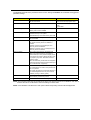
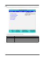
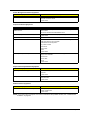
Revision History
Please refer to the table below for the updates made on TravelMate 2000/2500 service guide.
Date
2004/04/21
II
Chapter
Chapter 1
Updates
Add description about modem chipset on page 21
Copyright
Copyright © 2004 by Acer Incorporated. All rights reserved. No part of this publication may be reproduced,
transmitted, transcribed, stored in a retrieval system, or translated into any language or computer language, in
any form or by any means, electronic, mechanical, magnetic, optical, chemical, manual or otherwise, without
the prior written permission of Acer Incorporated.
Disclaimer
The information in this guide is subject to change without notice.
Acer Incorporated makes no representations or warranties, either expressed or implied, with respect to the
contents hereof and specifically disclaims any warranties of merchantability or fitness for any particular
purpose. Any Acer Incorporated software described in this manual is sold or licensed "as is". Should the
programs prove defective following their purchase, the buyer (and not Acer Incorporated, its distributor, or its
dealer) assumes the entire cost of all necessary servicing, repair, and any incidental or consequential
damages resulting from any defect in the software.
Intel is a registered trademark of Intel Corporation.
Pentium and Pentium II/III are trademarks of Intel Corporation.
Other brand and product names are trademarks and/or registered trademarks of their respective holders.
III
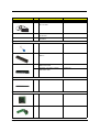
Conventions
The following conventions are used in this manual:
IV
Screen messages
Denotes actual messages that appear
on screen.
NOTE
Gives bits and pieces of additional
information related to the current
topic.
WARNING
Alerts you to any damage that might
result from doing or not doing specific
actions.
CAUTION
Gives precautionary measures to
avoid possible hardware or software
problems.
IMPORTANT
Reminds you to do specific actions
relevant to the accomplishment of
procedures.
Preface
Before using this information and the product it supports, please read the following general information.
1.
This Service Guide provides you with all technical information relating to the BASIC CONFIGURATION
decided for Acer "global" product offering. To better fit local market requirements and enhance product
competitiveness, your regional office MAY have decided to extend the functionality of a machine (e.g.
add-on card, modem, or extra memory capability). These LOCALIZED FEATURES will NOT be covered
in this generic service guide. In such cases, please contact your regional offices or the responsible
personnel/channel to provide you with further technical details.
2.
Please note WHEN ORDERING FRU PARTS, that you should check the most up-to-date information
available on your regional web or channel. If, for whatever reason, a part number change is made, it will
not be noted in the printed Service Guide. For ACER AUTHORIZED SERVICE PROVIDERS, your Acer
office may have a DIFFERENT part number code to those given in the FRU list of this printed Service
Guide. You MUST use the list provided by your regional Acer office to order FRU parts for repair and
service of customer machines.
V
VI
Table of Contents
Chapter 1
System Introduction
1
Features . . . . . . . . . . . . . . . . . . . . . . . . . . . . . . . . . . . . . . . . . . . . . . . . . . . . . . . . . 1
System Block Diagram . . . . . . . . . . . . . . . . . . . . . . . . . . . . . . . . . . . . . . . . . . . . . . 3
Board Layout . . . . . . . . . . . . . . . . . . . . . . . . . . . . . . . . . . . . . . . . . . . . . . . . . . . . . 4
Top View . . . . . . . . . . . . . . . . . . . . . . . . . . . . . . . . . . . . . . . . . . . . . . . . . . . . . 4
Bottom View . . . . . . . . . . . . . . . . . . . . . . . . . . . . . . . . . . . . . . . . . . . . . . . . . . 5
Panel . . . . . . . . . . . . . . . . . . . . . . . . . . . . . . . . . . . . . . . . . . . . . . . . . . . . . . . . . . . . 6
Front Panel . . . . . . . . . . . . . . . . . . . . . . . . . . . . . . . . . . . . . . . . . . . . . . . . . . . 6
Left Panel . . . . . . . . . . . . . . . . . . . . . . . . . . . . . . . . . . . . . . . . . . . . . . . . . . . . 7
Right Panel . . . . . . . . . . . . . . . . . . . . . . . . . . . . . . . . . . . . . . . . . . . . . . . . . . . 8
Rear Panel . . . . . . . . . . . . . . . . . . . . . . . . . . . . . . . . . . . . . . . . . . . . . . . . . . . 9
Bottom Panel . . . . . . . . . . . . . . . . . . . . . . . . . . . . . . . . . . . . . . . . . . . . . . . . 10
Indicators . . . . . . . . . . . . . . . . . . . . . . . . . . . . . . . . . . . . . . . . . . . . . . . . . . . . . . . 11
Understanding the icons . . . . . . . . . . . . . . . . . . . . . . . . . . . . . . . . . . . . . . . . 12
Keyboard . . . . . . . . . . . . . . . . . . . . . . . . . . . . . . . . . . . . . . . . . . . . . . . . . . . . . . . 13
Special keys . . . . . . . . . . . . . . . . . . . . . . . . . . . . . . . . . . . . . . . . . . . . . . . . . 13
Hot Keys . . . . . . . . . . . . . . . . . . . . . . . . . . . . . . . . . . . . . . . . . . . . . . . . . . . . . . . . 16
Hardware Specifications and Configurations . . . . . . . . . . . . . . . . . . . . . . . . . . . . 19
Chapter 2
System Utilities
34
BIOS Setup Utility . . . . . . . . . . . . . . . . . . . . . . . . . . . . . . . . . . . . . . . . . . . . . . . . . 34
Navigating the BIOS Utility . . . . . . . . . . . . . . . . . . . . . . . . . . . . . . . . . . . . . . 35
Information . . . . . . . . . . . . . . . . . . . . . . . . . . . . . . . . . . . . . . . . . . . . . . . . . . 36
Main . . . . . . . . . . . . . . . . . . . . . . . . . . . . . . . . . . . . . . . . . . . . . . . . . . . . . . . 37
Advanced . . . . . . . . . . . . . . . . . . . . . . . . . . . . . . . . . . . . . . . . . . . . . . . . . . . 39
Security . . . . . . . . . . . . . . . . . . . . . . . . . . . . . . . . . . . . . . . . . . . . . . . . . . . . . 41
Boot . . . . . . . . . . . . . . . . . . . . . . . . . . . . . . . . . . . . . . . . . . . . . . . . . . . . . . . . 45
Exit . . . . . . . . . . . . . . . . . . . . . . . . . . . . . . . . . . . . . . . . . . . . . . . . . . . . . . . . 46
BIOS Flash Utility . . . . . . . . . . . . . . . . . . . . . . . . . . . . . . . . . . . . . . . . . . . . . . . . . 47
Chapter 3
Machine Disassembly and Replacement
48
General Information . . . . . . . . . . . . . . . . . . . . . . . . . . . . . . . . . . . . . . . . . . . . . . . 49
Before You Begin . . . . . . . . . . . . . . . . . . . . . . . . . . . . . . . . . . . . . . . . . . . . . 49
Disassembly Procedure Flowchart . . . . . . . . . . . . . . . . . . . . . . . . . . . . . . . . . . . . 50
Removing the Battery . . . . . . . . . . . . . . . . . . . . . . . . . . . . . . . . . . . . . . . . . . . . . . 52
Removing the Memory Module . . . . . . . . . . . . . . . . . . . . . . . . . . . . . . . . . . . . . . . 53
Removing the Wireless LAN Board and the Modem Board . . . . . . . . . . . . . . . . . 54
Removing the Hard Disk Drive Module . . . . . . . . . . . . . . . . . . . . . . . . . . . . . . . . . 55
Disassembling the Hard Disk Drive Module . . . . . . . . . . . . . . . . . . . . . . . . . 55
Removing the LCD Module . . . . . . . . . . . . . . . . . . . . . . . . . . . . . . . . . . . . . . . . . . 56
Removing the Middle Cover . . . . . . . . . . . . . . . . . . . . . . . . . . . . . . . . . . . . . 56
Removing the Launch Board . . . . . . . . . . . . . . . . . . . . . . . . . . . . . . . . . . . . 56
Removing the LCD Module . . . . . . . . . . . . . . . . . . . . . . . . . . . . . . . . . . . . . . 57
Disassembling the LCD Module . . . . . . . . . . . . . . . . . . . . . . . . . . . . . . . . . . . . . . 59
Removing the LCD Bezel . . . . . . . . . . . . . . . . . . . . . . . . . . . . . . . . . . . . . . . 59
Removing the Inverter Board (15” LCD) . . . . . . . . . . . . . . . . . . . . . . . . . . . . 59
Removing the 15” TFT LCD . . . . . . . . . . . . . . . . . . . . . . . . . . . . . . . . . . . . . 60
Removing the LCD Brackets . . . . . . . . . . . . . . . . . . . . . . . . . . . . . . . . . . . . . 60
Removing the LCD Coaxial Cable . . . . . . . . . . . . . . . . . . . . . . . . . . . . . . . . 61
Removing the LCD Hinges . . . . . . . . . . . . . . . . . . . . . . . . . . . . . . . . . . . . . . 61
Disassembling the Main Unit . . . . . . . . . . . . . . . . . . . . . . . . . . . . . . . . . . . . . . . . 63
Removing the Keyboard . . . . . . . . . . . . . . . . . . . . . . . . . . . . . . . . . . . . . . . . 63
VII
Table of Contents
Removing the RTC Battery . . . . . . . . . . . . . . . . . . . . . . . . . . . . . . . . . . . . . . 63
Removing the Fan . . . . . . . . . . . . . . . . . . . . . . . . . . . . . . . . . . . . . . . . . . . . . 63
Removing the Thermal Module . . . . . . . . . . . . . . . . . . . . . . . . . . . . . . . . . . . 64
Removing the Processor . . . . . . . . . . . . . . . . . . . . . . . . . . . . . . . . . . . . . . . . 64
Installing the Processor . . . . . . . . . . . . . . . . . . . . . . . . . . . . . . . . . . . . . . . . . 65
Removing the Upper Case Assemly . . . . . . . . . . . . . . . . . . . . . . . . . . . . . . . 65
Removing the Touchpad Board . . . . . . . . . . . . . . . . . . . . . . . . . . . . . . . . . . 66
Removing the Touchpad Cable . . . . . . . . . . . . . . . . . . . . . . . . . . . . . . . . . . 66
Removing the VGA Thermal Plate . . . . . . . . . . . . . . . . . . . . . . . . . . . . . . . . 67
Removing the CPU Heatsink Plate . . . . . . . . . . . . . . . . . . . . . . . . . . . . . . . . 67
Removing the Second Fan Bracket . . . . . . . . . . . . . . . . . . . . . . . . . . . . . . . 68
Removing the ODD Module(1) . . . . . . . . . . . . . . . . . . . . . . . . . . . . . . . . . . . 68
Removing the ODD Module(2) . . . . . . . . . . . . . . . . . . . . . . . . . . . . . . . . . . . 68
Removing the HDD Bracket . . . . . . . . . . . . . . . . . . . . . . . . . . . . . . . . . . . . . 69
Removing the Main Board . . . . . . . . . . . . . . . . . . . . . . . . . . . . . . . . . . . . . . 69
Removing the DC Board . . . . . . . . . . . . . . . . . . . . . . . . . . . . . . . . . . . . . . . . 70
Removing the I/O Port Bracket . . . . . . . . . . . . . . . . . . . . . . . . . . . . . . . . . . . 70
Removing the PCMCIA Slot . . . . . . . . . . . . . . . . . . . . . . . . . . . . . . . . . . . . . 71
Removing the Speaker Set . . . . . . . . . . . . . . . . . . . . . . . . . . . . . . . . . . . . . . 72
System Upgrade Procedure . . . . . . . . . . . . . . . . . . . . . . . . . . . . . . . . . . . . . . . . . 73
Base Unit to Wireless Unit . . . . . . . . . . . . . . . . . . . . . . . . . . . . . . . . . . . . . . 73
Chapter 4
Troubleshooting
74
System Check Procedures . . . . . . . . . . . . . . . . . . . . . . . . . . . . . . . . . . . . . . . . . . 75
External Diskette Drive Check . . . . . . . . . . . . . . . . . . . . . . . . . . . . . . . . . . . 75
External CD-ROM Drive Check . . . . . . . . . . . . . . . . . . . . . . . . . . . . . . . . . . 75
Keyboard or Auxiliary Input Device Check . . . . . . . . . . . . . . . . . . . . . . . . . . 75
Memory check . . . . . . . . . . . . . . . . . . . . . . . . . . . . . . . . . . . . . . . . . . . . . . . . 76
Power System Check . . . . . . . . . . . . . . . . . . . . . . . . . . . . . . . . . . . . . . . . . . 76
Touchpad Check . . . . . . . . . . . . . . . . . . . . . . . . . . . . . . . . . . . . . . . . . . . . . . 78
Power-On Self-Test (POST) Error Message . . . . . . . . . . . . . . . . . . . . . . . . . . . . 79
Index of Error Messages . . . . . . . . . . . . . . . . . . . . . . . . . . . . . . . . . . . . . . . . . . . . 80
Index of Symptom-to-FRU Error Message . . . . . . . . . . . . . . . . . . . . . . . . . . . . . . 83
Intermittent Problems . . . . . . . . . . . . . . . . . . . . . . . . . . . . . . . . . . . . . . . . . . . . . . 86
Undetermined Problems . . . . . . . . . . . . . . . . . . . . . . . . . . . . . . . . . . . . . . . . . . . . 87
How to Build NAPP Master Hard Disc Drive . . . . . . . . . . . . . . . . . . . . . . . . . . . . . 88
CD to Disk Recovery . . . . . . . . . . . . . . . . . . . . . . . . . . . . . . . . . . . . . . . . . . . 88
Disk to Disk Recovery . . . . . . . . . . . . . . . . . . . . . . . . . . . . . . . . . . . . . . . . . . 91
Chapter 5
Jumper and Connector Locations
96
Top View . . . . . . . . . . . . . . . . . . . . . . . . . . . . . . . . . . . . . . . . . . . . . . . . . . . . 96
Bottom View . . . . . . . . . . . . . . . . . . . . . . . . . . . . . . . . . . . . . . . . . . . . . . . . . 97
Chapter 6
FRU (Field Replaceable Unit) List
98
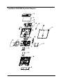
TravelMate 2000/2500 Exploded Diagram . . . . . . . . . . . . . . . . . . . . . . . . . . . . . . 99
Appendix A Model Definition and Configuration
110
Model Name Definition . . . . . . . . . . . . . . . . . . . . . . . . . . . . . . . . . . . . . . . . . . . . 110
Appendix B Test Compatible Components
112
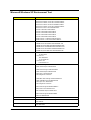
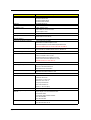
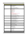
Microsoft Windows XP Environment Test . . . . . . . . . . . . . . . . . . . . . . . . . . . . . . 113
Appendix C Online Support Information
118
VIII
Chapter 1
System Introduction
Features
This computer was designed with the user in mind. Here are just a few of its many features:
Performance
T
Intel® Pentium® 4 (for TravelMate 2500) and Intel® Celeron® (for TravelMate 2000) processor,
2.40 GHz or above
T
Intel® Hyper-ThreadingTM technology
T
256/512 MB of DDR333 SDRAM standard, upgradeable to 2048MB with dual soDIMM modules
T
30 GB and above high-capacity, Enhanced-IDE hard disc drive
T
Advanced Configuration Power Interface (ACPI) power management system
T
14.1” or 15” Thin-Film Transistor (TFT) liquid crystal display (LCD) displaying 16.7 M color (with
FRC technology) at 1024x768 XGA (eXtended Graphics Array) resolution
T
ATI MOBILITYTM RadeonTM 9000 IGP (M9) chipset shared with 64MB of system memory, as video
RAM
T
Simultaneous LCD and CRT display support
T
Output display devices such as LCD projection panels for large-audience presentations support
T
“Automatic LCD dim” feature that automatically deciding the best settings for your display and
conserves power
T
Dual ViewTM Support
Display
Multimedia
T
High-speed DVD/CD-RW Combo or DVD-Dual drive
T
MS DirectSound compatible
T
Built-in dual speakers
Connectivity
T
Intergrated 10/100 Mbps Fast Ethernet connection
T
Built-in 56Kbps fax/data modem
T
Four USB (Universal Serial Bus) 2.0 ports
T
802.11b or 802.11g wireless LAN (manufacturing option)
T
Bluetooth (manufacturing option)
Human-centric design and ergonomics
T
Rugged, yet extremely portable design
T
Stylish appearance
T
Full-size keyboard with four programmable launch keys
T
Comfortable palm rest area with well-positioned touchpad
Expansion
T
Chapter 1
One Type III or two Type II CardBus PC Card slots
1
T
Upgrageable memory modules
T
One Type III or two Type II PC Card slot
T
One RJ-11 modem jack (V.92, 56K)
T
One RJ-45 network jack
T
One DC-in jack
T
One parallel port (ECP/EPP)
T
One external monitor port
T
One line-out jack (3.5mm mini jack)
T
One line-out jack (3.5mm mini jack)
T
One Infrared (FIR)port
T
Four USB 2.0 ports
I/O Ports
2
Chapter 1
Chapter 1
1
2
3
4
31
INT.SPKR
31
Line Out
Line In
Mic In 31
A
MODEM/BT
MDC Card
OP AMP
G1421
AC'97
CODEC
ALC655
22
31
30
Thermal &
2x FAN
G768D 20
11,12
3
Mobile P4
/Northwood
/Prescott
Intel CPU
HDD
21
B
21
X 4 22
USB
USB
2.0
21
PRN
Port29
C
PC87392
NS SIO
FIR
34
25/B/1
KBC
26
23
28
D
33
SST49LF040
32
LPC
4MB
21/B/2
24
14
D
33
32
LPC
DEBUG
CONN.
INT KB
25
PS/2
Debug
con 33
27
TWO SLOT
CARDBUS
RJ45
802.11A/B/G
Mini-PCI
27
TPS2224A
PWR SW
21
XGA/SXGA+
LCD
TV OUT
13
43
E
37
1D25V_S0
APL5331
1D5V_S0
2D5V_S5
36
OUTPUTS
1.2V
+VID
1.3V
0.3A
44A
+VCC_CORE
OUTPUTS
41
4.0A
5V
100mA
UP+5V
18V
BT+
OUTPUTS
E
Sheet
1
of
46
SA
Rev
8F, 88, Sec.1, Hsin Tai Wu Rd., Hsichih,
Taipei Hsien 221, Taiwan, R.O.C.
Acer Inc.
L6: Signal 4
L5: GND
L4: Signal 3
L3: Signal 2
L2: VCC/GND
L1: Signal 1
PCB LAYER
DCBATOUT
INPUTS
MAX1909
MAXIM CHARGER
DCBATOUT
INPUTS
MAX1546AETL 39,40
39
CM2843ACIM25
YUHINA3
Date: Friday, December 05, 2003
3D3V_S5
3D3V_S3
3D3V_S0
5V_S5
5V_S3
5V_S0
CPU DC/DC
2D5V_S3
DCBATOUT
INPUTS
38
OUTPUTS
SYSTEM DC/DC
TPS5110
DCBATOUT
INPUTS
TPS51020DBT
SYSTEM DC/DC
BLOCK DIAGRAM
35
Size
Document Number
Custom
Title
45
EMI
Power
Button
14
INVERTER
AD CONN
43
BAT CONN
42
ATTINY12L-4SI
Micro-P
: 03245-SA
REVISION
CRT
: 48.40I01.0SA
PCB P/N
Project code: 91.40I01.001
10/100Mb
Touch
Pad 33
M38857
PCI 1520
GHK
CARDBUS
RTL8100C
26/A/4
Realtek
LPC BUS 33MHz
PCI BUS
33MHz
FDD
16,17,18,19
ATI
IXP150
CD ROM
ATA100
PIDE
USB
2.0
AC-Link
6,7,8,9,10
4, 5
ALIK I/F
66MHz
ATI
RC300M
FSB
400/533/800MHz
266/333/400MHz
ICS951402AGT
CLK GEN.
DDR*2
C
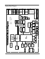
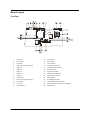
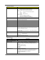
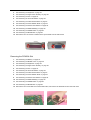
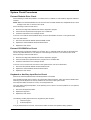
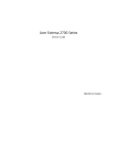
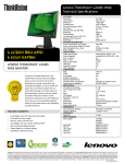
YUHINA3A Block Diagram
B
SIDE
A
1
2
3
4
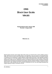
System Block Diagram
3
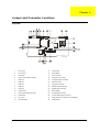
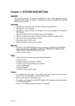
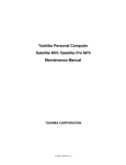
Board Layout
Top View
4
1
Line-in Port
15
CPU Socket
2
Line-out Port
16
North Bridge
3
RJ45+RJ11
17
Fan Connector
4
LCD Inverter Cable Connector
18
Second Fan Connector
5
USB Port
19
Touchpad Cable Connector
6
USB Port
20
HDD Connector
7
USB Port
21
Keyboard Connector
8
USB Port
22
Speaker Cable Connector
9
VGA Port
23
Optical Drive Connector
10
S-Video Port
24
South Bridge
11
LCD Coaxial Cable Connector
25
RTC Battery Connector
12
Parallel Port
26
Launch Board Cable Connector
13
DC-in Port
27
SW5 (Please see Chapter 5 for its settings)
14
LCD Lid Switch
28
PCMCIA Slot
Chapter 1
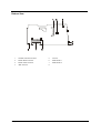
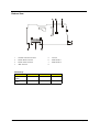
Bottom View
1
Wireless LAN Card Connector
5
FIR Port
2
Modem Board Connector
6
DIMM Socket 1
3
Modem Cable Connector
7
DIMM Socket 2
4
IEEE 1394 Port
8
Chapter 1
5
Panel
Ports allow you to connect peripheral devices to your computer as you would with a desktop PC.
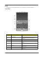
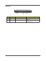
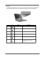
Front Panel
#
6
Item
Description
1
Display screen
Also called LCD (Liquid Crystal Display), displays computer
output.
2
Status indicators
LEDs (Light Emitting Diodes) that turn on and off to show
the status of the computer and its functions and
components.
3
Power button
Turns on the computer power.
4
Launch Keys
Buttons for launching frequently used programs.
5
Palmrest
Comfortable support area for your hands when you use the
computer.
6
Click buttons (left, center and right)
The left and right buttons function like the left and right
mouse buttons, the center button serves as a 4-way scroll
button.
7
Touchpad
Touch-sensitive pointing device which functions like a
computer mouse.
8
Keyboard
Inputs data into your computer.
9
Ventilation Slot
Enables the computer to stay cool, even after the
prolonged use.
Chapter 1
Left Panel
#
1
Icon
Item/ Port
PCMCIA (PC card) Port
Description
Connects to one Type III or two Type II CardBus
PC Card(s).
2
Eject buttons
Eject the PC cards from the slot.
3
Optical drive
Internal optical drive; accepts CDs or DVDs
depending on the optical drive type.
4
Infrared port
Interfaces with infrared devices (e.g., infrared
printer, IR-aware computer).
5
Eject button
Ejects the optical drive tray from teh drive.
6
LED indicator
Lights up when the optical drive is active.
7
Emergency eject slot
Ejects the optical drive tray when the computer is
turned off. There is a mechancial eject button on
the CD-ROM or DVD-ROM drive. Simply insert
the tip of a pen or paperclip and push to eject the
tray.
8
Speaker
Delivers stereo audio output.
Chapter 1
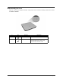
7
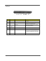
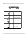
Right Panel
#
8
Icon
Item/ Port
Description
1
Speaker
Delivers stereo audio output.
2
Ventilation slots
Enable the computer to stay cool, even after
prolonged use.
3
Security keylock
Connects to a Kensington-compatible
computer security lock.
Chapter 1
Rear Panel
l
#
Icon
Port
Description
1
Power Jack
Connects to an AC adapter
2
Parallel port
Connects to a parallel device (e.g., parallel
printer).
3
Ventilation slot
Enables the computer to stay cool, even
after prolonged use.
4
External display port
Connects to a display device (e.g., external
monitor, LCD projector) and displays up to
16M colors(with FRC technology) at
1024x768 resolution
5
USB port (four)
Connects to Universal Serial Bus (USB) 2.0
devices(e.g., USB mouse, USB camera).
6
Network jack
Connects to an Ethernet 10/100-based
network
7
Modem jack
Connects to the phone line
8
Speaker/Line-Out/
Headphone jack
Connects to audio line-out devices (e.g.,
speakers, headphone).
9
Line-in/Mic-in jack
Accepts audio line-in devices (e.g., audio
CD player, stereo walkman).
Chapter 1
9
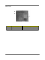
Bottom Panel
#
10
Item
Description
1
Battery bay
Houses the computer’s battery pack.
2
Battery release latch
Unlatches the battery to remove the battery pack.
3
Memory compartment
Houses the computer’s main memory.
Chapter 1
Indicators
The computer has seven easy-to-read status icons on the right of the display screen.
.
The Power and Standby status icons are visible even when you close the display cover so you can see the
status of the computer while the cover is closed.
#
Function
Description
1
Icon
Wireless
communication button
Lights when the Wireless LAN capability is
enabled.
2
Power
Lights when the computer is on.
3
Sleep
Lights when the computer enters Standby
mode and blinks when it enters into or
resumes from hibernation mode.
4
Media Activity
Lights when the floppy drive, hard disk or
optical drive is active.
5
Battery Charge
Lights when the battery is being charged.
6
Caps Lock
Lights when Caps Lock is activated.
7
Num Lock
Lights when Numeric Lock is activated.
(Fn-F11)
Chapter 1
11
Understanding the icons
When the cover of your computer is closed, 2 easy-to-read icons are shown, indicating which state or feature
is enabled or disabled.
#
12
Icon
Function
Description
1
Power
Lights up when the computer is on.
2
Sleep
Lights when the computer enters Standby
mode and blinks when it enters into or
resumes from hibernation mode.
Chapter 1
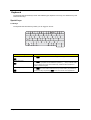
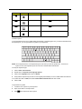
Keyboard
The keyboard has full-sized keys and an embedded keypad, separate cursor keys, two Windows keys and
twelve function keys.
Special keys
Lock keys
The keyboard has three lock keys which you can toggle on and off.
Lock key
Caps Lock
Description
When @is on, all alphabetic characters typed are in uppercase.
@
Num Lock (Fn-F11)
]
When ] is on, the embedded keypad is in numeric mode. The keys function
as a calculator (complete with the arithmetic operators ), -, *, and /). Use this mode
when you need to do a lot of numeric data entry. A better solution would be to
connect an external keypad.
Scroll Lock (Fn-F12)
When [ is on, the screen moves one line up or down when you press the up
[
or down arrow keys respectively. [ does not work with some applications.
Chapter 1
13
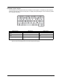
Embedded numeric keypad
The embedded numeric keypad functions like a desktop numeric keypad. It is indicated by small characters
located on the upper right corner of the keycaps. To simplify the keyboard legend, cursor-control key symbols
are not printed on the keys.
Desired access
Num lock on
Num lock off
Number keys on embedded
keypad
Type numbers in a normal manner.
Cursor-control keys on embedded
keypad
Hold Shift while using cursor-control keys.
Hold Fn while using cursor-control
keys.
Main keyboard keys
Hold Fn while typing letters on embedded
keypad.
Type the letters in a normal manner.
NOTE: If an external keyboard or keypad is connected to the computer, the Num Lock feature automatically
shifts from the internal keyboard to the external keyboard or keypad.
14
Chapter 1
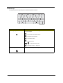
Windows keys
The keyboard has two keys that perform Windows-specific functions.
Keys
Windows logo key
Description
Start button. Combinations with this key perform shortcut functions. Below
are a few examples:
+ Tab (Activates next taskbar button)
+ E (Explores My Computer)
+ F (Finds Document)
+ M (Minimizes All)
j+
+ M (Undoes Minimize All)
+ R (Displays the Run... dialog box)
Application key
Chapter 1
Opens a context menu (same as a right-click).
15
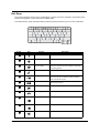
Hot Keys
The computer employs hot keys or key combinations to access most of the computer’s controls like screen
contrast and brightness, volume output and the BIOS Utility.
To activate hot keys, press and hold the Fn key before pressing the other key in the hot key combination.
Hot Key
16
Icon
Function
Description
Fn-l
Hotkey help
Displays a list of the hotkeys and their functions.
Fn-m
Setup
Accesses the notebook configuration utility.
Fn-n
Power Management
Scheme Toggle
Switches between the power management scheme
used by the computer (function available if supported
by operating system).
Fn-o
Sleep
Puts the computer in Sleep mode.
Fn-p
Display toggle
Switches display output between the display screen,
external monitor (if connected) and both the display
screen and external monitor.
Fn-q
Screen blank
Turns the display screen backlight off to save power.
Press any key to return.
Fn-r
Touchpad toggle
Turns the internal touchpad on and off.
Fn-s
Speaker toggle
Turns the speakers on and off; mutes the sound.
Fn-w
Volume up
Increases the sound volume.
Fn-y
Volume down
Decreases the sound volume.
Fn-x
Brightness up
Increases the screen brightness.
Chapter 1
Hot Key
Icon
Function
Description
Brightness down
Decreases the screen brightness.
Fn-{
Home
Functions as the g key.
Fn-}
End
Functions as the d key.
aGr-Euro
Euro
Types the Euro symbol.
Fn-¨z
The Euro symbol
If your keyboard layout is set to United States-International or United Kingdom or if you have a keyboard with a
European layout, you can type the Euro symbol on your keyboard.
NOTE: for US keyboard users: The keyboard layout is set when you first set up Windows. For the Euro
symbol to work, the keyboard layout has to be set to United States-international.
To verify the keyboard type:
1.
Click on Start, Control Panel.
2.
Double-click on Regional and Language Options.
3.
Click on the language tab and click on Details.
4.
Verify that the keyboard layout used for “En English (United States)” is set to United States-International.
If not, select and click on ADD, then select United States-International and click on OK.
5.
Click on OK.
To type the Euro symbol:
1.
Locate the Euro symbol on your keyboard.
2.
Open a text editor or word processor.
3.
Hold aGr and press the Euro symbol.
Chapter 1
17
Launch Keys
Located at the top of the keyboard are six buttons. These buttons are called lauch keys. They are designated
as mail button, Web browser button, P1, P2, Bluetooth and Wireless buttons. The Wireless and Bluetooth
buttons cannot be set by the user. To set the other four launch keys, run the Acer Launch Manager.
#
18
Icon
Function
Description
1
Mail
Email application
2
Web browser
Internet browser application
3
P1
User-programmable
4
P2
User-programmable
5
Bluetooth
Starts (optional) Bluetooth functionality and
indicates that (optional) Bluetooth is enabled.
6
Wireless
Opens (optional) wireless connectivity and
indicates status of (optional) wireless
communication.
Chapter 1
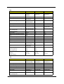
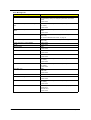
Hardware Specifications and Configurations
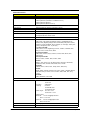
System Board Major Chips
Item
Controller
System core logic
ATI RC300M+ATI IXP150
Super I/O controller
NS PC87392
Audio controller
Realtek ALC655
Video controller
ATI Radeon 9700
Hard disk drive controller
Embedded in ATI IXP 150
Keyboard controller
Mitsubish LPC keyboard controller M38857
CardBus Controller
TI 1520
RTC
ATI IXP 150
Processor (for TravelMate 2000)
Item
CPU type
Specification
Intel® Cerelon® processor at 2.40 to 2.80 GHz; 400 MHz FSB
Intel® Celeron® Precott 2.53 to 3.2GHz, 533MHz FSB
CPU package
uFCBGA
CPU core voltage
High speed: 1.35V
CPU I/O voltage
High speed: 1.35V or 1.55V
Low speed: 1.2V
Low speed: 1.2V
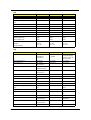
Processor (for TravelMate 2500)
Item
CPU type
Specification
Intel® Pentium® 4 processor at 2.60GHz, 400Mhz FSB
Intel® Pentium® 4 Northwood processor at 2.80 to 3.06GHz; 533 MHz FSB
Intel® Pentium® 4 Northwood processor at 3.0 to 3.4GHz; 800 MHz FSB
Intel® Pentium® 4 Prescott processor at 3 to 3.8GHz; 800 MHz FSB
Mobile Pentium® 4 3.06 to 3.20GHz, 533 Mhz FSB
CPU package
uFCBGA
CPU core voltage
1.35V
CPU I/O voltage
High speed: 1.35V or 1.55V
Low speed: 1.2V
BIOS
Item
BIOS vendor
Specification
Phoenix BIOS
BIOS Version
BIOS ROM type
Flash ROM
BIOS ROM size
BIOS package
Chapter 1
32 Pin PLCC
19
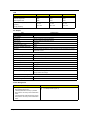
BIOS
Item
Specification
Supported protocols
ACPI 1.0b, SMBIOS 2.3, PCI 2.2, Boot Block, PXE 2.0, Mobile PC2001,
Hard Disk Password, INT 13h Extensions, PCI Bus Power Management
interface Specification, EI Torito-Bootable CD-ROM Format Specification
V1.0, Simple Boot Flag 1.0
BIOS password control
Set by switch, see SW5 settings on Chapter 5.
Second Level Cache
Item
Specification
Cache controller
Built-in CPU
Cache size
128KB for Cerelon® CPU; 512KB for Intel® Northwood CPU, Mobile
Pentium® 4 CPU and Cerelon® Prescott CPU; 1MB for Intel® Prescott CPU
128KB for Cerelon® CPU used in TM2000 series
512KB for Intel® Northwood, Mobile Pentium® 4 and Cerelon® Prescott CPU
used in TM2500 series and TM2000 series
1MB for Intel® Prescott CPU used in TM2500 series
1st level cache control
Always Enabled
2nd level cache control
Always Enabled
Cache scheme control
Fixed-in write back
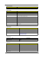
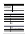
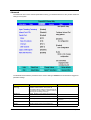
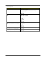
System Memory
Item
Memory controller
Specification
ATI RC300M
Onboard memory size
0MB
DIMM socket number
2 Sockets
Supports memory size per socket
128MB
Supports maximum memory size
2048MB
Supports DIMM type
DDR-DRAM
Supports DIMM Speed
333 MHz
Supports DIMM voltage
2.5 V
Supports DIMM package
200-pin so-DIMM
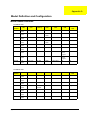
Memory module combinations
You can install memory modules in any combinations as long as they
match the above specifications .
Memory Combinations
Slot 1
0MB
20
Slot 2
128MB
Total Memory
128 MB
128MB
0MB
128 MB
128MB
128MB
256 MB
256MB
0MB
256MB
0MB
256MB
256MB
256MB
128MB
384MB
128MB
256MB
384MB
256MB
256MB
512MB
0MB
512MB
512MB
Chapter 1
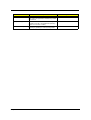
Memory Combinations
Slot 1
Slot 2
Total Memory
512MB
128MB
640MB
256MB
512MB
768MB
128MB
512MB
640MB
512MB
256MB
768MB
256MB
128MB
384MB
512MB
512MB
1024MB
0MB
512MB
512MB
Above table lists some system memory configurations. You may combine DIMMs with various capacities to
form other combinations.
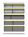
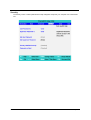
LAN Interface
Item
Specification
Chipset
RealTek 8100C
Supports LAN protocol
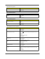
10/100Mbps
LAN connector type
RJ45
LAN connector location
Rear side
Modem Interface
Item
Specification
International Agere LU97 chipset (Scorpio+CSP1037B)--chipset on
modem board
Chipset
Built-in ATI IXP150--controller on the main board
Fax modem data baud rate (bps)
14.4K
Data modem data baud rate (bps)
56K
Supports modem protocol
V.90/V.92MDC
Modem connector type
RJ11
Modem connector location
Rear side
Floppy Disk Drive Interface
Item
Vendor & model name
Specification
Mitsumi D353G 4515
MCI JU-226A033FC
Floppy Disk Specifications
Media recognition
2DD (720KB)
2HD (1.2 MB, 3 mode)
2HD (1.44MB)
Sectors/track
9
15
18
Tracks
80
80
80
Data transfer rate
(Kbit/s)
1 MB
1.6 MB
2 MB
Rotational speed (RPM)
300
360
300
Read/write heads
2
Encoding method
MFM
Power Requirement
Input Voltage (V)
Chapter 1
+5V
21
.
Hard Disk Drive Interface
Item
Vendor & Model
Name
HGST Moraga
IC25N030ATMR04
HGST Moraga
IC25N040ATMR04-
HGST Moraga
IC25N060ATMR04-0
Fujitsu V-40 MHT2030AT
TOSHIBA Pluto 40G
MK4025GAS
HGST Fresno DK23FA-60
Seagate N1 ST93015A
Fujitsu V40+ MHT2040AT
TOSHIBA Neptune
MK6021GAS
Seagate N1 ST94019A
Capacity (MB)
30000
40000
60000
Bytes per sector
512
512
512
Logical heads
16
16
16
Logical sectors
63
63
63
Logical cylinders
16383
16383
16383
Physical read/write
heads
2/Not show/2
2/Not show/2/2
3/4
Drive Format
Disks
1/Not show/1
1/Not show/1/1
2
Spindle speed (RPM)
4200RPM
4200RPM
4200RPM
Performance Specifications
Buffer size
2MB
2MB/8MB for Toshiba
2MB/8MB for HGST
Interface
ATA-5 for other vendors /ATA6 for HGST and Toshiba
ATA-5 for other vendors /ATA6 for HGST
ATA-5 for other vendors /ATA6 for HGST
Data transfer rate
(disk-buffer, Mbytes/
s)
350
350
350
Data transfer, rate
(host~buffer, Mbytes/
s)
100 MB/Sec
100 MB/Sec
100MB/Sec
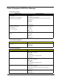
DC Power Requirements
Voltage tolerance
5 +/- 5%
5 +/- 5%
CD-ROM Interface
Items
Vendor & Model Name
Specification
QSI SCR242
Mitsumi SR244W1
Performance Specification
Brust Data Transfer rate
PIO mode 4:
16.7 MB/sec Max. (Mode 0~4)
Multi-word DMA mode 2:
16.7 MB/sec Max. (Mode 0~2)
Ultra DMA mode 2:
33.3MB/sec Max.
Access time (typ.)
QSIRandom: 90 ms
Full Stroke: 180 ms
MitsumiRandom: 100 ms
Full Stroke: 240 ms
22
Chapter 1
CD-ROM Interface
Items
Specification
Rotation speed
5100 rpm for QSI
5400 rpm for Mitsumi 24X CAV mode
Data Buffer Capacity
128 KB (built-in)
Interface
Compliant to ATA/ATAPI-6
Applicable disc format
QSI:
CD-DA, CD-ROM Mode-1, CD-ROM/XA Mode-2, Form-1 and Mode-2 Form-2, CD-i
Ready, Video-CD (MPEG-1), Karaoke CD, Photo-CD, Enhanced CD, CD Plus, CD
Extra, i-trax CD, CD-Text, CD-R and CD-RW
Mitsumi:
CD-DA, CD-ROM (Mode 1 and Mode2) CD-ROM XA (Mode 2 Form 1 and Form2),
CD-I (Mode2 Form 1 and Form 2), CD-I Bridge (Photo CD, CD EXTRA), Enhanced
CD, CD-RW, CD-R, CD-TEXT
Loading mechanism
Drawer with soft eject and emergency eject hole
Power Requirement
Input Voltage
+5V[DC]+/-5%
DVD-ROM Interface
Item
Specification
Vendor & model name
MKE SR-8177
Performance Specification
With CD Diskette
With DVD Diskette
Transfer rate (KB/sec)
Average Sustained:
DVD-5:
CAV mode
Normal Speed (1X) 11.08 Mbits/sec
775~1800 blocks/sec
CAV mode 36.67~88.64 Mbits/sec
(10.3X to 24X)
DVD-9/DVD-R:
1550~3600kBytes/sec (Mode 1)
Normal Speed (1X) 11.08 Mbits/sec
1768~4106 kBytes/sec (Mode 2)
CAV mode 36.67~88.64 Mbits/sec
Chapter 1
23
DVD-ROM Interface
Item
Average Full Access time (typ.)
Specification
Random
DVD-5:
CAV mode 110 msec typical 150
msec average max
Random
120 msec typical
160 msec average max
Full Stroke
CAV mode 200 msec typical 260
msec average max
Full Stroke
270 msec typical
350 msec average max
DVD-9:
Random
150 msec typical
200 msec average max
Full Stroke
340 msec typical
450 msec average max
DVD-RAM (2.6G)
Random
200 msec typical
300 msec average max
Full Stroke
300 msec typical
600 msec average max
DVD-RAM (4.7G)
Random
180 msec typical
300 msec average max
Full Stroke
320 msec typical
700 msec average max
Data Buffer Capacity
512 kBytes
Interface
IDE
Applicable disc format
DVD: DVD-5, DVD-9, DVD-10, DVD-R (3.95G), DVD-RAM (2.6G), DVDRAM (4.7G)
CD: CD-Audio, CD-ROM (mode 1 and mode 2), CD-ROM XA (mode 2, form
1 and form 2), CD-I (mode 2, form 1 and form 2), CD-I Ready, CD-I Bridge,
CD-WO, CD-RW, Photo CD, Video CD, Enhanced Music CD, CD-TEXT
Loading mechanism
Soft eject (with emergency eject hole)
Power Requirement
Input Voltage
+5V[DC]+/-5%
Combo Drive Interface
Item
Vendor & model name
Specification
KME UJDA750
Performance Specification
24
Chapter 1
Combo Drive Interface
Item
Transfer rate (KB/sec)
Specification
Read Sustained:
DVD-ROM MAX 8X CAV (MAX 10800 KB/sec)
CD-ROM
MAX 24X CAV (MAX 3600 KB/sec)
CD-R
4X, 8X (CLV), Max 16X, MAX 24X (ZCLV)
Write:
CD-RW
4X (CLV)
HS-RW
4X,8X, 10X (CLV)
ATAPI Interface:
PIO mode 16.6 MB/sec :PIO Mode 4
DMA mode 16.6 MB/sec:Multi word mode 2
Ultra DMA mode 33.3MB/sec: Ultra DMA mode 2
Buffer rate
2MB
Access time
DVD-ROM 180 ms typ. (1/3 stroke)
Start up time
less than 15s
Stop time
less than 6s
Acoustic noise
less than 50 dBA
CD-ROM 130 ms typ. (1/3 stroke)
Interface
Enhanced IDE (ATAPI) compatible
Master/Slave
Set by Cable Select (By host)
PC compatible
PC2001 compatible
Applicable disc format
CD:
CD-DA, CD-ROM, CD-ROM XA, CD-R, CD-RW, PhotoCD (multiSession),
Video CD, CD-Extra(CD+), CD-text
DVD: DVD-ROM, DVD-R, DVD-RW (Ver.1.1), DVD-VIDEO, DVD-RAM
(2.6GB, 4.7GB)
Slope
15 degree (Any direction)
Dimensions, Weight
128X129X12.7mm (WXDXH)
(except protrusion)
200g+- 10g
Eject
Soft Eject (with emergency eject hole)
DVD Dual Interface
Item
Vendor & model name
Specification
Liteon DVD-Dual SDW-431S
Disc type for read/write application
Applicable Formats
CD-DA, CD-TEXT, CD ROM Mode-1, CD-ROM/XA Mode-2 Form-1 and
Form-2, CD-I Ready, Video-CD (MPEG-1), Karaoke-CD, Photo-CD,
Enhance CD, CD extra, I-Trax CD and UDF DVD-ROM, DVD-Video, DVDAudio,
DVD-R single/multi border(s)
DVD+R single/multi session(s)
DVD-RW
DVD+RW
Applicable Media Type
CD-ROM, CD-R and CD-RW
DVD-ROM (4.7G/8.54G) single layer on single/double side (read only),
DVD-ROM dual layer (PTP/OTP) on single/double side (read only)
DVD-R (3.9G, 4.7G for General and Authoring),
DVD-RW, DVD+RW (4.7G)
DVD+R
Chapter 1
25
DVD Dual Interface
Item
Specification
Disc Diameter
12cm and 8cm
Capacity
2048 bytes/sector (DVD)
2048 bytes/block (CD Mode-1 and Mode-2 Form-1)
2336 bytes/block (Mode-2)
2328 bytes/block (Mode-2 Form-2)
Operation environment for “write/rewrite” application
Host Machine
IBM compatible PC (Pentium 166 MHz or above)
OS
MS-Windows 90/ME/2000/XP/NT 4.0
Memory
Min. 128MB required
Hard Disk
Empty Storage Capacity:100 MB or more
Average access time: 20ms or less
Disc Diameter
12cm and 8cm
Recommended Media
CD-R:
AMT, CMC, Csita, Delphi, EverMedia, Imation, LeadData(Silver-Sil),
Maxell, MCC (Bagdad), Mirage, Mitsui, MoserBaer(India), MPO, NanYa,
Plasmon, Prodisc, RAMedia, Ricoh, Ritek(JS, S, Richodye), SAST (ultra
green), SKC(Korea), TDK, TY (DX dye)
Low Speed CD-RW:
CMC, Daxon, Fornet, Gigastorage, Imation, Infodisc, LeadData, MCC,
Nanya, Princo, Prodisc, Ricoh, Ritek
High Speed CD-RW:
AMT, CMC, Infodisc, Nanya, Postech, Prodisc, Ritek, Ricoh, MCC,
SKC(Korea)
Ultra Speed CD-RW:
Daxon, Imation, Infodisc, MCC, Prodisc, Ritek
DVD+R:
BEALL, CMC, Daxon, Fuji, HP, Maxell, MCC, Memorex, OPTODISC,
PRODISC, Ricoh, RICOH, Ritek, SONY, TDK, TYUDE
DVD+RW:
CMMC, Daxon, Imation, MCC, Philips, Ricoh, Ritek, Sony
DVD-R:
BeAll, CMMC, DAXON, DVSN Fornex, GSC, Imation, LeadData, Maxell,
Mitsubishi, Nanya, Pioneer, Princo, Prodisc, Ritec, Ritek, SKC, Sony,
That’s
DVD-RW:
CMC, Mitsubishi, Princo Ritek
Mechanism
Pick-up
NA:
CD: 0.51
Focusing:
Astigmatism
Tracking:
CD: DPP
DVD: 0.65
DVD-ROM: DPD
DVD+R/RW: DPP
Wave length:
CD: 785+/- 5 nm
DVD: 650+/- 15 nm
Output power:
Read CD:
1.5 mw max@objective lens
DVD: 1.0 mw max
Write CD:
65 mw max2@objective lens
DVD: 20 mw max
26
Traverse mechanism
DC Stepping motor driven
Spindle motor
DC burshless motor
Chapter 1
DVD Dual Interface
Item
Loading mechanism
Specification
Manual load/DC brushless mortor system
Audio Interface
Item
Specification
Audio Controller
RTL ALC655
Audio onboard or optional
Built-in
Mono or Stereo
Stereo
Resolution
20 bit stereo Digital to Analog converter
18 bit stereo Analog to Digital converter
Compatibility
Microsoft PC98/PC99, AC97 2.1
Mixed sound source
Line-in, CD, Video, AUX
Voice channel
8/16 bit, mono/stereo
Sampling rate
44.1 KHz
Internal microphone
Yes
Internal speaker / Quantity
Yes
Supports PnP DMA channel
DMA channel 0
DMA channel 1
Supports PnP IRQ
IRQ10, IRQ11
Video Interface
Item
Specification
Vendor & Model Name
Built-in ATI RC300M(ATI Mobility Radeon 9000IGP)
Chip voltage
Core / 2.5V, 1.5V,
Supports ZV (Zoomed Video) port
NO
Maximum resolution (LCD)
1024 x768 (32bit colors)
Maximum resolution (CRT)
1024x768 (32 bit colors)
1280x1024 (32 bit colors)
1600x1200 (32 bit colors)
Video Memory
Item
Specification
Fixed or upgradeable
Fixed, share the system memory
Video memory size
64MB
Parallel Port
Item
Specification
Parallel port controller
NS PC87392
Number of parallel port
1
Location
Rear side
Connector type
25-pin D-type
Parallel port function control
Enable/Disable by BIOS Setup
Supports ECP/EPP
Yes (set by BIOS setup)
Optional ECP DMA channel
(in BIOS Setup)
DMA channel 1 and 3
Chapter 1
27
Parallel Port
Item
Specification
Optional parallel port I/O address
(in BIOS Setup)
378, 278, 3BC
Optional parallel port IRQ
(in BIOS Setup)
IRQ7, IRQ5
USB Port
Item
Specification
USB Compliancy Level
1.1/2.0 support
OHCI
USB 2.0
Number of USB port
4
5V/500 mA per slot
Location
Rear side
Other Remarks
3 independent OHCI USB1.1 Host Controller and 1 EHCI USN2.0
Host Controller.
PCMCIA Port
Item
Specification
PCMCIA controller
TZ 1520
Supports card type
Type II, Tpye III
Number of slots
Two type II, one type III
Access location
Left side
Supports ZV (Zoomed Video) port
Yes
Supports 32 bit CardBus
Yes (IRQ17)
Keyboard
Item
Specification
Keyboard controller
Mitsubishi LPC keyboard controller M38857
Keyboard vendor & model name
API
Total number of keypads
84-/85-/88- key
Windows 95 keys
Yes
Internal & external keyboard work simultaneously
Yes
Battery
Item
Vendor & model name
28
Specification
SIMPLO
Battery Type
Li-ION
Pack capacity
4000mAH
Cell voltage
3.8V / 1.2V
Number of battery cell
8
Package configuration
4S2P
Package voltage
41.8V / 9.6V
Chapter 1
LCD
Item
Vendor & model name
AU:
CMO:
LG:
B150XG01
N150X3-L05
LP150X08-A5
B150PG01
Screen Diagonal (mm)
381
15.0 inches, 381
15.0 inches, 381
Active Area (mm)
304.1x228.1
304.1x228.1
304.1x228.1
1024x768 XGA
1024x768 XGA
304.5x228.375
Display resolution (pixels)
1024x768 XGA
1400x1050 SXGA+
Pixel Pitch
0.297x0.297
0.297x0.297
0.297x0.297
Pixel Arrangement
R.G.B. Vertical Stripe
R.G.B. Vertical Stripe
R.G.B. Vertical Stripe
Display Mode
Normally White
Normally White
Transmissive mode,
Normally White
Typical White Luminance (cd/m2)
180 (5 point average)
170
150 (5 point average)
also called Brightness
150 (5 point average)
Luminance Uniformity
N/A
N/A
N/A
Contrast Ratio
300/250
250
250
Response Time (Optical Rise Time/Fall
Time)
24/11
6/17
10/20
15/35
Nominal Input Voltage VDD
+3.3V Typ.
+3.3V Typ.
+3.3V Typ.
Typical Power Consumption (watt)
5.6/5.7
4.4
4.66
Weight
550
505
540
Physical Size(mm)
317.3x242.0x6.0
317.3x242.0x5.7
317.3x241.5x5.7
1 channel LVDS
N/A
N/A
262K colors (RGB 6bit data driver)
262,144 colors
262,144 colors
Horizontal: Right/Left
40/40
45/45
45/45
Vertial: Upper/Lower
10/30
15/35
15/35
0 to +50
0 to +50
N/A
-20 to +60
-20 to +60
+5 to +35
Samsung:
Electrical Interface
2 channel LVDS
Support Color
Viewing Angle (degree)
Temperature Range( ° C)
Operating
Storage (shipping)
LCD
Item
Vendor & model name
Hitachi
QDI
TX38D81VC1CAB
QD15XL06-01
LTN150P4-L03
Screen Diagonal (mm or inch)
15.0 inches, 381
15.0 inches
15.0 inches
Active Area (mm)
304.1x228.1
304.1x228.1
304.5x228.375
Display resolution (pixels)
1024x768 XGA
1024x768 XGA
1400x1050 SXGA+
Pixel Pitch
0.297x0.297
0.099x0.297
0.2175x0.2175
Pixel Arrangement
R.G.B. Vertical Stripe
R.G.B. Vertical Stripe
R.G.B. Vertical Stripe
Display Mode
Transmissive &
normally White
Normally White
Normally White
Typical White Luminance (cd/m2)
170
160
150
also called Brightness
Chapter 1
29
LCD
Item
Luminance Uniformity
40
N/A
N/A
Contrast Ratio
200
300
200
Response Time (Optical Rise Time/Fall
Time)
30/30
8/17
10/30
Nominal Input Voltage VDD
+3.3V
+3.3V
+3.3V
Typical Power Consumption (watt)
N/A
3.96
4.0
Weight
580
570
600
Physical Size(mm)
317.3x242.1x6.0
317.3x242.0x5.9
317.3x242.0x6.5
Electrical Interface
1 channel LVDS
1 channel LVDS
2 channel LVDS
Support Color
262K
262,144
262,144
Horizontal: Right/Left
40/40
45/45
45/45
Vertial: Upper/Lower
20/40
15/35
20/40
0 to +40
0 to +50
0 to +50
-20 to +60
-25 to +60
-25 to +60
Hannstar
AU
HSD150PX14
B141XN04
CMO N141XBL01(SPWG-B type)
Viewing Angle (degree)
Temperature Range( ° C)
Operating
Storage (shipping)
LCD
Item
Vendor & model name
Hydis HT14X19-100
(SPWG-B type)
HSD150PK14
Screen Diagonal (mm)
Active Area (mm)
15.0 inches
14.1 inches
14.1 inches
304.1x228.1
285.7x214.3
285.7x214.3
1024x768 XGA
1024x768 XGA
0.279x0.279
0.279x0.279
R.G.B. Vertical Stripe
R.G.B. Vertical Stripe
R.G.B. Vertical Stripe
Normally White
Normally White
Normally White
150
150
160/150
304.5x228.375
Display resolution (pixels)
1024x768 XGA
1400x1050 SXGA+
Pixel Pitch
0.297x0.297
0.2175x0.2175
Pixel Arrangement
Display Mode
2
Typical White Luminance (cd/m )
180
Luminance Uniformity
70/65
N/A
N/A
Contrast Ratio
250
250
450/200
Response Time (Optical Rise Time/Fall
Time)
10/25
20/30
6/17
Nominal Input Voltage VDD
3.3V
3.3V
3.3V
Typical Power Consumption (watt)
N/A
3.96
4.03
Weight
600/590
445
420/485
Physical Size(mm)
317.3x242.0x6.5
298.5x226.7x5.2
299x228x5.2
1 channel LVDS
1 channel LVDS
262,144
262,144
7/15
23/30
N/A
317.3x242.0x6.3
Electrical Interface
1 channel LVDS
299x228x5.7
2 channel LVDS
Support Color
30
262,144
Chapter 1
LCD
Item
Viewing Angle (degree)
Horizontal: Right/Left
40/40
40/40
45/45
Vertial: Upper/Lower
20/40
10/30
15/35
0 to +50
0 to +50
0 to +50
-20 to +60
-20 to +60
-20 to +60
Temperature Range( ° C)
Operating
Storage (shipping)
AC Adapter
Item
Vendor & model name
Specification
Liton, 135W power supply
Input Voltage
Low Range
90(min.)/137(max.)/100-127(nominal)
High Range
180(min.)/265(max.)200-240(nominal)
Input current
2.2A(max)
Nominal frequency (Hz)
50-60
Frequency variation range (Hz)
47-63
Efficiency
It should provide an efficiency of 85% minimum, when measured at maximum
load under 115Vac.
Output Requirements
DC output voltage
19V
Noise + Ripple
380mV as output voltage is 19V
Peak Load
18.5V-19.71V
Dynamic Output Characteristics
Turn-on delay time
5 sec (@ 115Vac)
Hold up time
5ms (@115Vac, Full load)
Over Voltage Protection (OVP)
29V
Short circuit protection
9.5A @19V output voltage
Electrostatic discharge (ESD)
15KV (at air discharge)
8KV (at contact discharge)
Dielectric Withstand Voltage
Primary to secondary
2150VDC for 1 sec.
Ground leakage current
less than 250uA
Power Management
Power Saving Mode
Standby Mode
Enter Standby Mode when
Phenomenon
T
T
The buzzer beeps
The Sleep indicator lights up
1.Standby/Hibernation hot-key is pressed
and system is not ready to enter Hibernation
mode.
2.System standby/ Hibernation timer expires
and system is not ready to enter Hibernation
mode.
Chapter 1
31
Power Management
Power Saving Mode
Phenomenon
Hibernation Mode
T
All power shuts off
T
The display shuts off
T
Hard disk drive is in standby mode.
(spindle turned-off)
Enter Hibernation Mode (suspend to HDD)
when
1.Hibernation hot-key is pressed and
system is ready to enter Hibernation mode
2.System Hibernation timer expires and
system is ready to enter Hibernation mode.
Display Standby Mode
Keyboard, built-in touchpad, and an external
PS/2 pointing device are idle for a specified
period.
Hard Disk Standby Mode
Hard disk is idle within a specified period of
time.
Environmental Requirements
Item
Specification
Temperature
Operating
+5~+35 °C
Non-operating
-10~+60 °C
Package storage
-20~+60 °C
Humidity
Operating
20% to 85% RH, non-condensing
Non-operating
20% to 80% RH, non-condensing (Unpacked)
Non-operating
20% to 90% RH, non-condensing (Storage package)
Vibration
Operating (unpacked)
5~25.6Hz: 0.38mm (peak to peak)
25.6~250Hz: 0.5G
Non-operating (unpacked)
5~27.1Hz: 0.6G
27.1~50Hz: 0.04mm (peak to peak)
50~500Hz: 2.0G
Non-operating (packed)
5~62.6Hz: 0.51mm (peak to peak)
62.6~500Hz: 4.0G
Mechanical Specification
Item
32
Specification
Dimensions
326(W) x 290(D) x 43.6(max. H)mm
Weight
7.32 Ibs (3.3kg) for 14.1” TFT LCD model with battery/7.50Ibs (3.4kg) for 15”LCD
model with battery
I/O Ports
One Type III or two type II PCMCIA (PC Card) port, one RJ-11 port, one RJ-45
port, one DC-in port, one ECP parallel port, four USB ports, one microphone-in/
line-in jack, one line-out ack, one FIR port.
Drive Bays
One
Material
Plastic
Indicators
Power-on, Standby, Battery Status, Media Access, CapsLock and NumLock
Switch
Power
Chapter 1
Chapter 1
33
Chapter 2
System Utilities
BIOS Setup Utility
The BIOS Setup Utility is a hardware configuration program built into your computer’s BIOS (Basic Input/
Output System).
Your computer is already properly configured and optimized, and you do not need to run this utility. However, if
you encounter configuration problems, you may need to run Setup. Please also refer to Chapter 4
Troubleshooting when problem arises.
To activate the BIOS Utility, press m during POST (when “Press <F2> to enter Setup” message is prompted
on the bottom of screen).
Press m to enter setup. The default parameter of F12 Boot Menu is set to “disabled”. If you want to change
boot device without entering BIOS Setup Utility, please set the parameter to “enabled”.
Press <F12> during POST to enter multi-boot menu. In this menu, user can change boot device without
entering BIOS SETUP Utility.
Chapter 2
34
Navigating the BIOS Utility
There are six menu options: Info., Main, System Devices, Security, Boot, and Exit.
Follow these instructions:
T
To choose a menu, use the cursor left/right keys (zx).
T
To choose a parameter, use the cursor up/down keys ( wy).
T
To change the value of a parameter, press por q.
T
A plus sign (+) indicates the item has sub-items. Press e to expand this item.
T
Press ^ while you are in any of the menu options to go to the Exit menu.
T
In any menu, you can load default settings by pressing t. You can also press u to save any
changes made and exit the BIOS Setup Utility.
NOTE: You can change the value of a parameter if it is enclosed in square brackets. Navigation keys for a
particular menu are shown on the bottom of the screen. Help for parameters are found in the Item
Specific Help part of the screen. Read this carefully when making changes to parameter values.
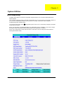
This menu provides you the information of the system.
35
Chapter 2
Information
NOTE: The system information is subject to different models.
Parameter
Floppy Disk Drive
Description
Shows floppy drive type informaiton.
Note: Aspre 1620, Extensa 2700, TravelMate 2500 and Extnesa 2500 series products do
not have floppy disk drive; Extensa 2000 and TravelMate 2000 series have floppy disk
drive.
HDD Model Name
This field shows the model name of HDD installed on primary IDE master.
HDD Serial Number
This field displays the serial number of HDD installed on primary IDE master.
ATAPI Model Name
This field displays the mofel name of devices installed on secondary IDE master. The hard
disk drive or optical drive model name is automatically detected by the system.
ATAPI Serial Number
This field shows the serial number of devices installed on secondary IDE master.
Serial Number
This field displays the serial number of this unit.
UUID Number
This will be visible only when an internal LAN device is presenting.
UUID=32bytes
Chapter 2
36
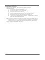
Main
The Main screen displays a summary of your computer hardware information, and also includes basic setup
parameters. It allows the user to specify standard IBM PC AT system parameters.
NOTE: The screen above is for reference only. Actual values may differ.
37
Chapter 2
The table below describes the parameters in this screen. Settings in boldface are the default and suggested
parameter settings.
Parameter
Description
Format/Option
System Time
Sets the system time. The hours are displayed
with 24-hour format.
Format: HH:MM:SS
(hour:minute:second) System Time
System Date
Sets the system date.
Format MM/DD/YYYY (month/day/
year)
System Date
System Memory
This field reports the memory size of the system.
Memory size is fixed to 640MB
Extended Memory
This field reports the memory size of the
extended memory in the system.
Extended Memory size=Total memory size-1MB
VGA Memory
Shows the VGA memory size. VGA Memory
size=64/128MB
Fast Boot
Determines if Customer Logo will be displayed or
not; shows Summary Screen is disabled or
enabled.
Option: Enabled or Disabled
Enabled: Customer Logo is displayed, and
Summary Screen is disabled.
Disabled: Customer Logo is not displayed, and
Summary Screen is enabled.
Power on display
Auto: During power process, the system will
detect if any display device is connected on
external video port. If any external display device
is connected, the power on display will be in CRT
(or projector) only mode. Otherwise it will be in
LCD only mode.
Option: Auto or Both
Both: Simultaneously enable both the integrated
LCD screen and the system’s external video port
(for an external CRT or projector).
LCD Auto Dim
Determines if the system will automatically dim
the LCD brightness in order to save power when
AC is not present.
Option: Enabled or Disabled
The system will support an automatic dimming of
the LCD backlight when the AC power is NOT
available (running on battery power).
PXE Boot from LAN
Enables, disables the system boot from LAN
(remote server). PXE is the protocal.
Option: Enabled or Disabled
F12 Boot Menu
Enables, disables Boot Menu during POST.
Option: Disabled or Enabled
NOTE: The sub-items under each device will not be shown if the device control is set to disable or auto. This is
because the user is not allowed to control the settings in these cases.
NOTE: If user disables “PXE Boot from LAN” option in BIOS Setup Utility, this item will be disappeared.
Chapter 2
38
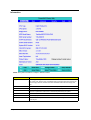
Advanced
The Advanced menu screen contains parameters involving your hardware devices. It also provides advanced
settings of the system.
The table below describes the parameters in the screen. Settings in boldface are the default and suggested
parameter settings.
.
Parameter
39
Description
Options
Hyper-Threading
Technology
The function is supported only when the CPU
installed is 3.06G or above. The system will
automatically hide this selection when detecting the
CPU frequency is below 3.06G or the CPU does not
support Hyper-Threading Technoloty.
Enabled/Disabled
Infrared Port
Enables, disables or auto detects the infrared port.
Disabled/Disabled/Auto
Parallel Port
Enables, disables or auto detects the parallel port.
Enabled/Disabled/Auto
Mode
Sets the operation mode of the parallel port.
ECP, EPP, Output only or Bidirectional
Base I/O address
Sets the I/O address of the parallel port.
378/278
Interrupt
Sets the interrupt request of the parallel port.
IRQ7/IRQ5
Chapter 2
Parameter
Description
Options
DMA channel
Sets a DMA channel for the printer to operate in
ECP mode. This parameter is enabled only if Mode
is set to ECP.
DMA3/DMA1
Legacy USB Support
Enables, disables USB interface devices support.
(Enable for use with a non-USB aware Operating
System such as DOS or UNIX).
Option: Disabled or Enabled
Hard Disk Recovery
Enables or disables Hard Disk to Hard Disk system
Recovery by pressing Fn+F10 key during POST.
Option: Disabled or Enabled
Chapter 2
40
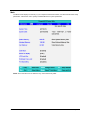
Security
The Security screen contains parameters that help safeguard and protect your computer from unauthorized
use.
41
Chapter 2
The table below describes the parameters in this screen. Settings in boldface are the default and suggested
parameter settings.
Parameter
Description
Option
User Password is
Shows the setting of the user password.
Clear or Set
Supervisor Password is
Shows the setting of the Supervisor password
Clear or Set
Set User Password
Press Enter to set the user password. When
set, this password protects the BIOS Setup
Utility from unauthorized access.
Set Supervisor Password
Press Enter to set the supervisor password.
When set, this password protects the BIOS
Setup Utility from unauthorized access.
Primary Harddisk Security
This feature is available to user when
Supervisor password is set. Password can be
written on HDD only when Supervisor
password or user password is set and
password on HDD is set to enabled.
Supervisor Password is written to HDD only
when Supervisor password is being set. User
password is written to HDD when both
passwords are set. When both Supervisor and
user password are present, both passwords
can unlock the HDD.
Disabled or Enabled
Password on Boot
Defines whether a password is required or not
while the events defined in this group
happened. The following sub-options are all
requires the Supervisor password for changes
and should be grayed out if the user password
was used to enter setup.
Disabled or Enabled
NOTE: When you are prompted to enter a password, you have three tries before the system halts. Don’t forget
your password. If you forget your password, you may have to return your notebook computer to your
dealer to reset it.
Setting a Password
Follow these steps as you set the user or the supervisor password:
1.
Use the w andy keys to highlight the Set Supervisor Password parameter and press the e key. The
Set Supervisor Password box appears:
2.
Type a password in the “Enter New Password” field. The password length can not exceeds 8
alphanumeric characters (A-Z, a-z, 0-9, not case sensitive). Retype the password in the “Confirm New
Password” field.
IMPORTANT:Be very careful when typing your password because the characters do not appear on the screen.
3.
4.
Press e.
After setting the password, the computer sets the User Password parameter to “Set”.
If desired, you can opt to enable the Password on boot parameter.
5.
When you are done, press u to save the changes and exit the BIOS Setup Utility.
Chapter 2
42
Removing a Password
Follow these steps:
1.
Use the w and y keys to highlight the Set Supervisor Password parameter and press the e key. The
Set Password box appears:
2.
Type the current password in the Enter Current Password field and press e.
3.
Press e twice without typing anything in the Enter New Password and Confirm New Password fields.
The computer then sets the Supervisor Password parameter to “Clear”.
4.
When you have changed the settings, press u to save the changes and exit the BIOS Setup Utility.
Changing a Password
1.
Use the w and y keys to highlight the Set Supervisor Password parameter and press the e key. The
Set Password box appears:
2.
Type the current password in the Enter Current Password field and press e.
3.
Type a password in the Enter New Password field. Retype the password in the Confirm New Password
field.
4.
Press e. After setting the password, the computer sets the User Password parameter to “Set”.
5.
If desired, you can enable the Password on boot parameter.
6.
When you are done, press u to save the changes and exit the BIOS Setup Utility.
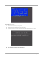
If the verification is OK, the screen will display as following.
The password setting is complete after the user presses u.
43
Chapter 2
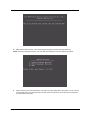
If the current password entered does not match the actual current password, the screen will show you the
Setup Warning.
If the new password and confirm new password strings do not match, the screen will display the following
message.
Chapter 2
44
Boot
This menu allows the user to decide the order of boot devices to load the operating system. Bootable devices
includes the distette drive in module bay, the onboard hard disk drive and the CD-ROM in module bay.
45
Chapter 2
Exit
The Exit screen contains parameters that help safeguard and protect your computer from unauthorized use.
The table below describes the parameters in this screen.
Parameter
Description
Exit Saving Changes
Exit System Setup and save your changes to CMOS.
Exit Discarding Changes
Exit utility without saving setup data to CMOS.
Load Setup Default
Load default values for all SETUP item.
Discard Changes
Load previous values from CMOS for all SETUP items.
Save Changes
Save Setup Data to CMOS.
Chapter 2
46
BIOS Flash Utility
The BIOS flash memory update is required for the following conditions:
T
New versions of system programs
T
New features or options
T
Restore a BIOS when it becomes corrupted.
Use the Phlash utility to update the system BIOS flash ROM.
NOTE: If you do not have a crisis recovery diskette at hand, then you should create a Crisis Recovery
Diskette before you use the Phlash utility.
NOTE: Do not install memory-related drivers (XMS, EMS, DPMI) when you use the Phlash.
NOTE: Please use the AC adaptor power supply when you run the Phlash utility. If the battery pack does not
contain enough power to finish BIOS flash, you may not boot the system because the BIOS is not
completely loaded.
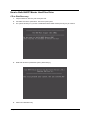
Fellow the steps below to run the Phlash.
47
1.
Prepare a bootable diskette.
2.
Copy the Phlash utilities to the bootable diskette.
3.
Then boot the system from the bootable diskette. The Phlash utility has auto-execution function.
Chapter 2
Chapter 3
Machine Disassembly and Replacement
This chapter contains step-by-step procedures on how to disassemble the notebook computer for
maintenance and troubleshooting.
To disassemble the computer, you need the following tools:
T
Wrist grounding strap and conductive mat for preventing electrostatic discharge
T
Flat-bladed screw driver
T
Phillips screw driver
T
Tweezers
T
Plastic Flat-bladed screw driver
Hexed Screw Driver
NOTE: The screws for the different components vary in size. During the disassembly process, group the
screws with the corresponding components to avoid mismatch when putting back the components.
T
NOTE: This chapter has been revised from previous model (TravelMate 240/250). Please refer to the
disassembling procedures instead of the images. Some of the images below contain the parts used in
TravelMate 240/250, but not in TravelMate 2000/2500.
Chapter 3
48
General Information
Before You Begin
Before proceeding with the disassembly procedure, make sure that you do the following:
49
1.
Turn off the power to the system and all peripherals.
2.
Unplug the AC adapter and all power and signal cables from the system.
Chapter 3
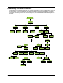
Disassembly Procedure Flowchart
The flowchart on the succeeding page gives you a graphic representation on the entire disassembly sequence
and instructs you on the components that need to be removed during servicing. For example, if you want to
remove the main board, you must first remove the keyboard, then disassemble the inside assembly frame in
that order.
Start
Battery
*2
*2
HDD Module
DIMM Cover
Modem Cover
Hinge Caps
G*2
D*2
HDD
HDD Holder
Wireless LAN
Board
Memory
J*2
Modem Board
Middle Cover
*2
F*6
RTC Battery
Keyboard
LCD Module
Launch Board
J*3
J*5
F*10
D*4
Second Fan
*4
Lower Case
Assembly
Upper Case
Assembly
J*3
Second Fan
Bracket
J*2
D*4
Wireless LAN
Antenna
FDD Module
F*1
J*4
ODD Module
Thermal
Module
*1
ODD Support
Bracket
HDD Bracket
CPU Heatsink
Plate
Touchpad
Cover
CPU
J*7
VGA Thermal
Plate
Touchpad
Button Pad
D*2
*4
ODD Bracket
ODD
Main Board
D*2
DC Board
Touchpad
Scroll Key
Touchpad
D*4
PCMCIA Slot
Touchpad
Cable
Upper Case
*2
Speaker Set
Chapter 3
50
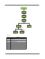
LCD Module
4 LCD
Cushions
E*4
LCD Bezel
L*1
Inverter
L*4
LCD
LCD Panel
H*8 for 14.1"
H*6 for 15.0"
LCD Coaxial
Cable
LCD Brackets
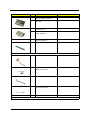
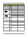
Screw List
Item
A
51
Description
SCREW MAC FLAT M2.5*L4 NI NYLOK
(86.00123.630)
B
SCREW M2.0*L10 NYLOK(86.9A352.100)
C
SCREW M2*3 NYLON 1JMCPC420325(86.9A352.3R0)
D
SCREW M2.5X6(86.9A353.6R0)
E
SCREW M3x4 (86.9A524.4R0)
F
SCREW M2X2.0 (86.9A552.2R0)
G
SCREW WAFER NYLOK NI 2ML3 (86.9A552.3R0)
H
SCRW M2*4 WAFER NI (86.9A552.4R0)
I
SCRW M2.5*3 WAFER NI (86.9A553.3R0)
J
SCREW M2.5*4L NI (86.9A553.4R0)
Chapter 3
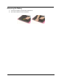
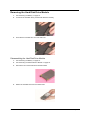
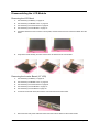
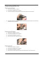
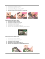
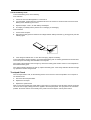
Removing the Battery
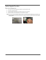
1.
To remove the battery, push the battery release latch.
2.
Then slide the battery out from the machine.
Chapter 3
52
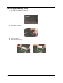
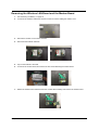
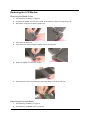
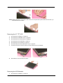
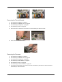
Removing the Memory Module
53
1.
See “Removing the Battery” on page 52.
2.
To remove the memory module from the machine, first remove the two screws holding the dimm cover.
3.
Remove the dimm cover.
4.
Pop up the memory.
5.
Then remove the memory.
Chapter 3
Removing the Wireless LAN Board and the Modem Board
1.
See “Removing the Battery” on page 52.
2.
To remove the wireless LAN board, first remove the two screws holding the modem cover.
3.
Remove the modem cover from the machine.
4.
Disconnect the wireless antennae.
5.
Pop out the wireless LAN board.
6.
To remove the modem board, first remove the two screws fastening the modem board.
7.
Detach the modem board and disconnect the modem cable carefully, then remove the modem board.
Chapter 3
54
Removing the Hard Disk Drive Module
1.
See “Removing the Battery” on page 52.
2.
To remove the hard disk drive, pull the hard disk dirve carefully.
3.
Then take the hard disk drive out of the main unit.
Disassembling the Hard Disk Drive Module
55
1.
See “Removing the Battery” on page 52.
2.
See “Removing the Hard Disk Drive Module” on page 55.
3.
Remove the two screws that fasten the HDD holder.
4.
Detach the hard disk drive from the HDD holder.
Chapter 3
Removing the LCD Module
Removing the Middle Cover
1.
See “Removing the Battery” on page 52.
2.
To remove the middle cover, first use a plastic flat screwdriver to remove the right hinge cap.
3.
Remove the screw that secures the middle cover.
4.
Remove the left hinge cap.
5.
Then remove the screw holding the middle cover on the other side.
6.
Detach the middle cover from the machine.
7.
Disconnect the launch board cable then remove the middle cover off the main unit.
.
Removing the Launch Board
1.
See “Removing the Battery” on page 52.
2.
See “Removing the Middle Cover” on page 56.
Chapter 3
56
3.
Remove the two screws and then detach the launch board from the middle cover.
Removing the LCD Module
57
1.
See “Removing the Battery” on page 52.
2.
See “Removing the Middle Cover” on page 56.
3.
See “Removing the Launch Board” on page 56.
4.
Remove the screw that fastens the LCD coaxial cable and disconnect the cable. Then disconnect the
LCD inverter cable.
5.
Remove the four screws holding the LCD hinge; two on the right and two on the left.Remove the four
screws holding the LCD hinge; two on the right and two on the left.
6.
Remove the two screws on the bottom; one on the right and the other on the left.
7.
Then you can remove the entire LCD module from the main unit.
Chapter 3
Chapter 3
58
Disassembling the LCD Module
Removing the LCD Bezel
1.
See “Removing the Battery” on page 52.
2.
See “Removing the Middle Cover” on page 56.
3.
See “Removing the Launch Board” on page 56.
4.
See “Removing the LCD Module” on page 57.
5.
Use plastic tweezers to remove the four screw pads, and then remove the four screws that fasten the LCD
bezel.
6.
Snap off the bezel carefully, and then remove the LCD bezel from the LCD module.
Removing the Inverter Board (15” LCD)
59
1.
See “Removing the Battery” on page 52.
2.
See “Removing the Middle Cover” on page 56.
3.
See “Removing the Launch Board” on page 56.
4.
See “Removing the LCD Module” on page 57.
5.
See “Removing the LCD Bezel” on page 59.
6.
To remove the inverter board, first remove one screw from the inverter board.
7.
Disconnect the LCD power cable then disconnect the inverter cable from the inverter board.
Chapter 3
NOTE: Please arrange the LCD inverter cable well to the LCD panel as the picture below shows when you
reassemble the LCD module.
Removing the 15” TFT LCD
1.
See “Removing the Battery” on page 52.
2.
See “Removing the Middle Cover” on page 56.
3.
See “Removing the Launch Board” on page 56.
4.
See “Removing the LCD Module” on page 57.
5.
See “Removing the LCD Bezel” on page 59.
6.
See “Removing the Inverter Board (15” LCD)” on page 59.
7.
To remove the LCD, first remove the four screws that secure the LCD hinges.
8.
Then take the LCD out of the LCD panel.
Removing the LCD Brackets
1.
See “Removing the Battery” on page 52.
Chapter 3
60
2.
See “Removing the Middle Cover” on page 56.
3.
See “Removing the Launch Board” on page 56.
4.
See “Removing the LCD Module” on page 57.
5.
See “Removing the LCD Bezel” on page 59.
6.
See “Removing the Inverter Board (15” LCD)” on page 59.
7.
See “Removing the 15” TFT LCD” on page 60.
8.
Remove the four screws holding the right LCD bracket.Then remove the right bracket.
9.
Remove the four screws holding the left LCD bracket. Then remove the left bracket..
Removing the LCD Coaxial Cable
1.
See “Removing the Battery” on page 52.
2.
See “Removing the Middle Cover” on page 56.
3.
See “Removing the Launch Board” on page 56.
4.
See “Removing the LCD Module” on page 57.
5.
See “Removing the LCD Bezel” on page 59.
6.
See “Removing the Inverter Board (15” LCD)” on page 59.
7.
See “Removing the 15” TFT LCD” on page 60.
8.
Tear off the mylar fastening the LCD coaxial cable, then disconnect the coaxial cable.
Removing the LCD Hinges
1.
61
See “Removing the Battery” on page 52.
Chapter 3
2.
See “Removing the Middle Cover” on page 56.
3.
See “Removing the Launch Board” on page 56.
4.
See “Removing the LCD Module” on page 57.
5.
See “Removing the LCD Bezel” on page 59.
6.
See “Removing the Inverter Board (15” LCD)” on page 59.
7.
See “Removing the 15” TFT LCD” on page 60.
8.
Remove the screw holding the right hinge, then remove the right hinge.
9.
Remove the screw holding the left hinge, then remove the left hinge.
Chapter 3
62
Disassembling the Main Unit
Removing the Keyboard
1.
See “Removing the Battery” on page 52.
2.
See “Removing the Middle Cover” on page 56.
3.
To remove the keyboard, carefully pull the keyboard out and upwards as the pticute shows.
4.
Use a plastic tweezers or a plastic flat screwdriver to disconnect the keyboard cable from the main board
carefully, then remove the keyboard.
Removing the RTC Battery
1.
See “Removing the Battery” on page 52.
2.
See “Removing the Middle Cover” on page 56.
3.
See “Removing the Keyboard” on page 63.
4.
Disconnect the RTC battery cable then remove it.
Removing the Fan
63
1.
See “Removing the Battery” on page 52.
2.
See “Removing the Middle Cover” on page 56.
3.
See “Removing the Keyboard” on page 63.
4.
Disconnect the fan cable and remove the three screws fastening the fan. Then remove the fan.
Chapter 3
Removing the Thermal Module
1.
See “Removing the Battery” on page 52.
2.
See “Removing the Middle Cover” on page 56.
3.
See “Removing the Keyboard” on page 63.
4.
See “Removing the Fan” on page 63.
5.
Disconnect the fan cable then remove the four screws fastening the thermal module.
6.
Then remove the thermal module.
Removing the Processor
1.
See “Removing the Battery” on page 52.
2.
See “Removing the Middle Cover” on page 56.
3.
See “Removing the Keyboard” on page 63.
4.
See “Removing the RTC Battery” on page 63.
5.
See “Removing the Fan” on page 63.
6.
See “Removing the Thermal Module” on page 64.
7.
Lift up the CPU socket lever. Then remove the CPU. Remember to press down the lever as the video
shows after you remove the CPU.
Chapter 3
64
Installing the Processor
1.
See “Removing the Battery” on page 52.
2.
See “Removing the Middle Cover” on page 56.
3.
See “Removing the Keyboard” on page 63.
4.
See “Removing the RTC Battery” on page 63.
5.
See “Removing the Fan” on page 63.
6.
See “Removing the Thermal Module” on page 64.
7.
Lift up the CPU lever, then place the CPU back to the CPU socket. Please remember to press the CPU
lever after you put the CPU back to the socket.
Removing the Upper Case Assemly
65
1.
See “Removing the Keyboard” on page 63.
2.
Disconnect the touchpad cable.
3.
Remove the 5 screws that secure the upper case to the lower case. Then turn over the main unit and
remove the 15 screws holding the lower case to the upper case.
Chapter 3
4.
Then take the upper case assembly off the main unit.
Removing the Touchpad Board
1.
See “Removing the Battery” on page 52.
2.
See “Removing the Middle Cover” on page 56.
3.
See “Removing the Keyboard” on page 63.
4.
See “Removing the Upper Case Assemly” on page 65.
5.
To detach the touch pad board, first disconnect the touch pad cable from the touch pad board with a
plastic tweezers.Then release the touchpad cover lock on the back as the picture shows.
6.
Remove the touchpad cover, the remove the touchpad button pad. Finally remove the touchpad board
from the upper case.
Removing the Touchpad Cable
1.
See “Removing the Battery” on page 52.
2.
See “Removing the Middle Cover” on page 56.
Chapter 3
66
3.
See “Removing the LCD Module” on page 57.
4.
See “Removing the Keyboard” on page 63.
5.
See “Removing the Upper Case Assemly” on page 65.
6.
See “Removing the Touchpad Board” on page 66.
7.
Remove the touchpad scroll key then remove the touchpad cable.
Removing the VGA Thermal Plate
1.
See “Removing the Battery” on page 52.
2.
See “Removing the Middle Cover” on page 56.
3.
See “Removing the Keyboard” on page 63.
4.
See “Removing the Fan” on page 63.
5.
See “Removing the Thermal Module” on page 64.
6.
Remove the seven screws holding the VGA thermal plate then remove it.
Removing the CPU Heatsink Plate
67
1.
See “Removing the Battery” on page 52.
2.
See “Removing the Middle Cover” on page 56.
3.
See “Removing the Keyboard” on page 63.
4.
See “Removing the Fan” on page 63.
5.
See “Removing the Thermal Module” on page 64.
6.
Remove the screw that fastens the CPU heatsink plate then remove it.
Chapter 3
Removing the Second Fan Bracket
1.
See “Removing the Battery” on page 52.
2.
See “Removing the Middle Cover” on page 56.
3.
See “Removing the LCD Module” on page 57.
4.
See “Removing the RTC Battery” on page 63.
5.
See “Removing the Fan” on page 63.
6.
See “Removing the Thermal Module” on page 64.
7.
Remove the three screws that fasten the second fan bracket then remove the bracket.
Removing the ODD Module(1)
1.
See “Removing the Battery” on page 52.
2.
Remove the screw that fastens the ODD bracket on the bottom. Push the ODD module at the point the
red arrow indicates hard.Then remove the ODD module from the lower case.
NOTE: If you need to replace the ODD module only, you can remove the ODD module as the steps above.
Removing the ODD Module(2)
1.
See “Removing the Battery” on page 52.
2.
See “Removing the Middle Cover” on page 56.
3.
See “Removing the Keyboard” on page 63.
4.
See “Removing the Upper Case Assemly” on page 65.
5.
See “Removing the Thermal Module” on page 64.
6.
See “Removing the VGA Thermal Plate” on page 67.
7.
Push the ODD module outwards then take the ODD out of the support bracket. Remove the screw that
fastens the ODD support bracket then remove it.
Chapter 3
68
Removing the HDD Bracket
1.
See “Removing the Battery” on page 52.
2.
See “Removing the Middle Cover” on page 56.
3.
See “Removing the Keyboard” on page 63.
4.
See “Removing the Upper Case Assemly” on page 65.
5.
Remove the four screws holding the HDD bracket, then remove the HDD bracket.
Removing the Main Board
1.
See “Removing the Battery” on page 52.
2.
See “Removing the Middle Cover” on page 56.
3.
See “Removing the Keyboard” on page 63.
4.
See “Removing the Upper Case Assemly” on page 65.
5.
See “Removing the Fan” on page 63.
6.
See “Removing the Thermal Module” on page 64.
7.
See “Removing the VGA Thermal Plate” on page 67.
8.
See “Removing the CPU Heatsink Plate” on page 67.
9.
See “Removing the Second Fan Bracket” on page 68.
10. See “Removing the ODD Module(2)” on page 68.
11. See “Removing the HDD Bracket” on page 69.
12. Disconnect the launch board cable. Tear off the tape that fastens the speaker set cable. Then disconnect
the speaker set cable.
69
Chapter 3
.
13. Remove the two screws holding the main board as the picture shows. Remove another two screws that
fasten the main board. Then detach the main board from the lower case carefully.
Removing the DC Board
1.
See “Removing the Battery” on page 52.
2.
See “Removing the Middle Cover” on page 56.
3.
See “Removing the Keyboard” on page 63.
4.
See “Removing the Upper Case Assemly” on page 65.
5.
See “Removing the Fan” on page 63.
6.
See “Removing the Thermal Module” on page 64.
7.
See “Removing the VGA Thermal Plate” on page 67.
8.
See “Removing the CPU Heatsink Plate” on page 67.
9.
See “Removing the Second Fan Bracket” on page 68.
10. See “Removing the ODD Module(2)” on page 68.
11. See “Removing the HDD Bracket” on page 69.
12. See “Removing the Main Board” on page 69.
13. Remove the two screws that fasten the DC board. Then detach the DC board from the lower case.
Removing the I/O Port Bracket
1.
See “Removing the Battery” on page 52.
2.
See “Removing the Middle Cover” on page 56.
Chapter 3
70
3.
See “Removing the Keyboard” on page 63.
4.
See “Removing the Upper Case Assemly” on page 65.
5.
See “Removing the Fan” on page 63.
6.
See “Removing the Thermal Module” on page 64.
7.
See “Removing the VGA Thermal Plate” on page 67.
8.
See “Removing the CPU Heatsink Plate” on page 67.
9.
See “Removing the Second Fan Bracket” on page 68.
10. See “Removing the ODD Module(2)” on page 68.
11. See “Removing the HDD Bracket” on page 69.
12. See “Removing the Main Board” on page 69.
13. Remove the four hex screws to detach the I/O port bracket from the main board.
Removing the PCMCIA Slot
1.
See “Removing the Battery” on page 52.
2.
See “Removing the Middle Cover” on page 56.
3.
See “Removing the Keyboard” on page 63.
4.
See “Removing the Upper Case Assemly” on page 65.
5.
See “Removing the Fan” on page 63.
6.
See “Removing the Thermal Module” on page 64.
7.
See “Removing the VGA Thermal Plate” on page 67.
8.
See “Removing the CPU Heatsink Plate” on page 67.
9.
See “Removing the Second Fan Bracket” on page 68.
10. See “Removing the ODD Module(2)” on page 68.
11. See “Removing the HDD Bracket” on page 69.
12. See “Removing the Main Board” on page 69.
13. Remove the four screws that secure the PCMCIA slot, then remove the PCMCIA slot from the lower case.
71
Chapter 3
Removing the Speaker Set
1.
See “Removing the Battery” on page 52.
2.
See “Removing the Middle Cover” on page 56.
3.
See “Removing the Keyboard” on page 63.
4.
See “Removing the Upper Case Assemly” on page 65.
5.
See “Removing the Fan” on page 63.
6.
See “Removing the Thermal Module” on page 64.
7.
See “Removing the VGA Thermal Plate” on page 67.
8.
See “Removing the CPU Heatsink Plate” on page 67.
9.
See “Removing the Second Fan Bracket” on page 68.
10. See “Removing the ODD Module(2)” on page 68.
11. See “Removing the HDD Bracket” on page 69.
12. See “Removing the Main Board” on page 69.
13. See “Removing the DC Board” on page 70.
14. Tear off the tape fastening the speaker set cable. Then remove the four screws that secure the speaker
set. Remove the speaker set from the lower case.
Chapter 3
72
System Upgrade Procedure
Base Unit to Wireless Unit
1.
Turn out the two screws fastening the modem cover then open the cover.
2.
Connect the wirless antennae.
3.
Insert the wireless LAN board to the wireless socket on the main board.
4.
Close the modem cover and fasten the cover with the two screws.
NOTE: You must connect the wireless antennae before you insert the wireless LAN board to the socket. If you
insert the wireless LAN card first, the pressure you press to fasten the wireless antennae may damage
the main board.
73
Chapter 3
Chapter 4
Troubleshooting
Use the following procedure as a guide for computer problems.
NOTE: The diagnostic tests are intended to test only Acer products. Non-Acer products, prototype cards, or
modified options can give false errors and invalid system responses.
1.
Obtain the failing symptoms in as much detail as possible.
2.
Verify the symptoms by attempting to re-create the failure by running the diagnostic test or by repeating
the same operation.
3.
Use the following table with the verified symptom to determine which page to go to.
Symptoms (Verified)
Go To
Power failure. (The power indicator does not go
on or stay on.)
“Power System Check” on page 76.
POST does not complete. No beep or error
codes are indicated.
“Power-On Self-Test (POST) Error Message” on
page 79
“Undetermined Problems” on page 87
POST detects an error and displayed messages
on screen.
“Error Message List” on page 80
Other symptoms (i.e. LCD display problems or
others).
“Power-On Self-Test (POST) Error Message” on
page 79
Symptoms cannot be re-created (intermittent
problems).
Use the customer-reported symptoms and go to
“Power-On Self-Test (POST) Error Message” on
page 79
“Intermittent Problems” on page 86
“Undetermined Problems” on page 87
Chapter 4
74
System Check Procedures
External Diskette Drive Check
Do the following to isolate the problem to a controller, driver, or diskette. A write-enabled, diagnostic diskette is
required.
NOTE: Make sure that the diskette does not have more than one label attached to it. Multiple labels can cause
damage to the drive or cause the drive to fail.
Do the following to select the test device.
1.
Boot from the diagnostics diskette and start the diagnostics program.
2.
See if FDD Test is passed as the program runs to FDD Test.
3.
Follow the instructions in the message window.
If an error occurs with the internal diskette drive, reconnect the diskette connector on the system board.
If the error still remains:
1.
Reconnect the external diskette drive/DVD-ROM module.
2.
Replace the external diskette drive/CD-ROM module.
3.
Replace the main board.
External CD-ROM Drive Check
Do the following to isolate the problem to a controller, drive, or CD-ROM. Make sure that the CD-ROM does
not have any label attached to it. The label can cause damage to the drive or can cause the drive to fail.
Do the following to select the test device:
1.
Boot from the diagnostics diskette and start the diagnostics program.
2.
See if CD-ROM Test is passed when the program runs to CD-ROM Test.
3.
Follow the instructions in the message window.
If an error occurs, reconnect the connector on the System board. If the error still remains:
1.
Reconnect the external diskette drive/CD-ROM module.
2.
Replace the external diskette drive/CD-ROM module.
3.
Replace the main board.
Keyboard or Auxiliary Input Device Check
Remove the external keyboard if the internal keyboard is to be tested.
If the internal keyboard does not work or an unexpected character appears, make sure that the flexible cable
extending from the keyboard is correctly seated in the connector on the system board.
If the keyboard cable connection is correct, run the Keyboard Test.
If the tests detect a keyboard problem, do the following one at a time to correct the problem. Do not replace a
non-defective FRU:
1.
Reconnect the keyboard cables.
2.
Replace the keyboard.
3.
Replace the main board.
The following auxiliary input devices are supported by this computer:
T
Numeric keypad
T
External keyboard
If any of these devices do not work, reconnect the cable connector and repeat the failing operation.
75
Chapter 4
Memory check
Memory errors might stop system operations, show error messages on the screen, or hang the system.
1.
Boot from the diagnostics diskette and start the doagmpstotics program (please refer to main board.
2.
Go to the diagnostic memory in the test items.
3.
Press F2 in the test items.
4. Follow the instructions in the message window.
NOTE: Make sure that the DIMM is fully installed into the connector. A loose connection can cause an error.
Power System Check
To verify the symptom of the problem, power on the computer using each of the following power sources:
1.
Remove the battery pack.
2.
Connect the power adapter and check that power is supplied.
3.
Disconnect the power adapter and install the charged battery pack; then check that power is supplied by
the battery pack.
If you suspect a power problem, see the appropriate power supply check in the following list:
Chapter 4
T
“Check the Power Adapter” on page 77
T
“Check the Battery Pack” on page 78
76
Check the Power Adapter
Unplug the power adapter cable from the computer and measure the output voltage at the plug of the power
adapter cable. See the following figure
Pin 1: +19 to +20.5V
Pin 2: 0V, Ground
1.
If the voltage is not correct, replace the power adapter.
2.
If the voltage is within the range, do the following:
T
Replace the System board.
T
If the problem is not corrected, see “Undetermined Problems” on page 87.
T
If the voltage is not correct, go to the next step.
NOTE: An audible noise from the power adapter does not always indicate a defect.
77
3.
If the power-on indicator does not light up, check the power cord of the power adapter for correct
continuity and installation.
4.
If the operational charge does not work, see “Check the Battery Pack” on page 78.
Chapter 4
Check the Battery Pack
To check the battery pack, do the following:
From Software:
1.
Check out the Power Management in control Panel
2.
In Power Meter, confirm that if the parameters shown in the screen for Current Power Source and Total
Battery Power Remaining are correct.
3.
Repeat the steps 1 and 2, for both battery and adapter.
4.
This helps you identify first the problem is on recharging or discharging.
From Hardware:
1.
Power off the computer.
2.
Remove the battery pack and measure the voltage between battery terminals 1(+) and 6(ground). See the
following figure
3.
If the voltage is still less than 7.5 Vdc after recharging, replace the battery.
To check the battery charge operation, use a discharged battery pack or a battery pack that has less than 50%
of the total power remaining when installed in the computer.
If the battery status indicator does not light up, remove the battery pack and let it return to room temperature.
Re-install the battery pack.
If the charge indicator still does not light up, replace the battery pack. If the charge indicator still does not light
up, replace the DC/DC charger board.
Touchpad Check
If the touchpad doesn’t work, do the following actions one at a time to correct the problem. Do not replace a
non-defective FRU:
1.
Reconnect the touchpad cables.
2.
Replace the touchpad.
3.
Replace the system board.
After you use the touchpad, the pointer drifts on the screen for a short time. This self-acting pointer movement
can occur when a slight, steady pressure is applied to the touchpad pointer. This symptom is not a hardware
problem. No service actions are necessary if the pointer movement stops in a short period of time.
Chapter 4
78
Power-On Self-Test (POST) Error Message
The POST error message index lists the error message and their possible causes. The most likely cause is
listed first.
NOTE: Perform the FRU replacement or actions in the sequence shown in FRU/Action column, if the FRU
replacement does not solve the problem, put the original part back in the computer. Do not replace a
non-defective FRU.
This index can also help you determine the next possible FRU to be replaced when servicing a computer.
If the symptom is not listed, see “Undetermined Problems” on page 87.
The following lists the error messages that the BIOS displays on the screen and the error symptoms classified
by function.
NOTE: Most of the error messages occur during POST. Some of them display information about a hardware
device, e.g., the amount of memory installed. Others may indicate a problem with a device, such as the
way it has been configured.
NOTE: If the system fails after you make changes in the BIOS Setup Utility menus, reset the computer, enter
Setup and install Setup defaults or correct the error.
79
Chapter 4
Index of Error Messages
Error Code List
Error Codes
006
Error Messages
Equipment Configuration Error
Causes:
1. CPU BIOS Update Code Mismatch
2. IDE Primary Channel Master Drive Error
(THe causes will be shown before “Equipment Configuration
Error”)
010
Memory Error at xxxx:xxxx:xxxxh (R:xxxxh, W:xxxxh)
070
Real Time Clock Error
071
CMOS Battery Bad
072
CMOS Checksum Error
110
System disabled.
Incorrect password is specified.
<No error code>
Battery critical LOW
In this situation BIOS will issue 4 short beeps then shut down
system, no message will show.
<No error code>
Thermal critical High
In this situation BIOS will shut down system, not show message.
Error Message List
Error Messages
Failure Fixed Disk
FRU/Action in Sequence
Reconnect hard disk drive connector.
“Load Default Settings” in BIOS Setup Utility.
Hard disk drive
System board
Stuck Key
see “Keyboard or Auxiliary Input Device Check” on page 75.
Keyboard error
see “Keyboard or Auxiliary Input Device Check” on page 75.
Keyboard Controller Failed
see “Keyboard or Auxiliary Input Device Check” on page 75.
Keyboard locked - Unlock key switch
Unlock external keyboard
Monitor type does not match CMOS - Run Setup
Run “Load Default Settings” in BIOS Setup Utility.
Shadow RAM Failed at offset: nnnn
BIOS ROM
System board
System RAM Failed at offset: nnnn
DIMM
System board
Extended RAM Failed at offset: nnnn
DIMM
System board
System battery is dead - Replace and run Setup
Replace RTC battery and Run BIOS Setup Utility to reconfigure
system time, then reboot system.
System CMOS checksum bad - Default
configuration used
RTC battery
System timer error
RTC battery
Run BIOS Setup Utility to reconfigure system time, then reboot
system.
Run BIOS Setup Utility to reconfigure system time, then reboot
system.
System board
Chapter 4
80
Error Message List
Error Messages
Real time clock error
FRU/Action in Sequence
RTC battery
Run BIOS Setup Utility to reconfigure system time, then reboot
system.
System board
Previous boot incomplete - Default configuration
used
Run “Load Default Settings” in BIOS Setup Utility.
RTC battery
System board
Memory size found by POST differed from
CMOS
Run “Load Default Settings” in BIOS Setup Utility.
DIMM
System board
Diskette drive A error
Check the drive is defined with the proper diskette type in BIOS
Setup Utility
See “External Diskette Drive Check” on page 75.
Incorrect Drive A type - run SETUP
Check the drive is defined with the proper diskette type in BIOS
Setup Utility
System cache error - Cache disabled
System board
CPU ID:
System board
DMA Test Failed
DIMM
System board
Software NMI Failed
DIMM
System board
Fail-Safe Timer NMI Failed
DIMM
System board
Device Address Conflict
Run “Load Default Settings” in BIOS Setup Utility.
RTC battery
System board
Allocation Error for device
Run “Load Default Settings” in BIOS Setup Utility.
RTC battery
System board
Failing Bits: nnnn
DIMM
BIOS ROM
System board
Fixed Disk n
None
Invalid System Configuration Data
BIOS ROM
System board
I/O device IRQ conflict
Run “Load Default Settings” in BIOS Setup Utility.
RTC battery
System board
Operating system not found
Enter Setup and see if fixed disk and drive A: are properly identified.
Diskette drive
Hard disk drive
System board
81
Chapter 4
Error Message List
No beep Error Messages
No beep, power-on indicator turns off and LCD is
blank.
FRU/Action in Sequence
Power source (battery pack and power adapter). See “Power
System Check” on page 76.
Ensure every connector is connected tightly and correctly.
Reconnect the DIMM.
LED board.
System board.
No beep, power-on indicator turns on and LCD is
blank.
Power source (battery pack and power adapter). See “Power
System Check” on page 76.
Reconnect the LCD connector
Hard disk drive
LCD inverter ID
LCD cable
LCD Inverter
LCD
System board
No beep, power-on indicator turns on and LCD is
blank. But you can see POST on an external
CRT.
Reconnect the LCD connectors.
LCD inverter ID
LCD cable
LCD inverter
LCD
System board
No beep, power-on indicator turns on and a
blinking cursor shown on LCD during POST.
No beep during POST but system runs correctly.
Ensure every connector is connected tightly and correctly.
System board
Speaker
System board
Chapter 4
82
Index of Symptom-to-FRU Error Message
LCD-Related Symptoms
Symptom / Error
LCD backlight doesn't work
Action in Sequence
LCD is too dark
Enter BIOS Utility to execute “Load Setup Default Settings”, then
reboot system.
LCD brightness cannot be adjusted
Reconnect the LCD connectors.
LCD contrast cannot be adjusted
Keyboard (if contrast and brightness function key doesn't work).
LCD inverter ID
LCD cable
LCD inverter
LCD
System board
Unreadable LCD screen
Reconnect the LCD connector
Missing pels in characters
LCD inverter ID
Abnormal screen
LCD cable
Wrong color displayed
LCD inverter
LCD
System board
LCD has extra horizontal or vertical lines
displayed.
LCD inverter ID
LCD inverter
LCD cable
LCD
System board
Indicator-Related Symptoms
Symptom / Error
Indicator incorrectly remains off or on, but system
runs correctly
Action in Sequence
Reconnect the inverter board
Inverter board
System board
Power-Related Symptoms
Symptom / Error
Power shuts down during operation
Action in Sequence
Power source (battery pack and power adapter). See “Power
System Check” on page 76.
Battery pack
Power adapter
Hard drive & battery connection board
System board
The system doesn’t power-on.
Power source (battery pack and power adapter). See “Power
System Check” on page 76.
Battery pack
Power adapter
Hard drive & battery connection board
System board
The system doesn’t power-off.
Power source (battery pack and power adapter). See “Power
System Check” on page 76.
Hold and press the power switch for more than 4 seconds.
System board
Battery can’t be charged
See “Check the Battery Pack” on page 78.
Battery pack
System board
83
Chapter 4
PCMCIA-Related Symptoms
Symptom / Error
System cannot detect the PC Card (PCMCIA)
Action in Sequence
PCMCIA slot assembly
System board
PCMCIA slot pin is damaged.
PCMCIA slot assembly
Memory-Related Symptoms
Symptom / Error
Memory count (size) appears different from
actual size.
Action in Sequence
Enter BIOS Setup Utility to execute “Load Default Settings, then
reboot system.
DIMM
System board
Speaker-Related Symptoms
Symptom / Error
In Windows, multimedia programs, no sound
comes from the computer.
Action in Sequence
Audio driver
Speaker
System board
Internal speakers make noise or emit no sound.
Speaker
System board
Power Management-Related Symptoms
Symptom / Error
The system will not enter hibernation
Action in Sequence
Keyboard (if control is from the keyboard)
Hard disk drive
System board
The system doesn't enter hibernation mode and
four short beeps every minute.
See “Hibernation Mode” on page 32.
Press Fn+oand see if the computer enters hibernation mode.
Touchpad
Keyboard
Hard disk connection board
Hard disk drive
System board
The system doesn’t enter standby mode after
closing the LCD
See “Hibernation Mode” on page 32.
LCD cover switch
System board
The system doesn't resume from hibernation
mode.
See “Hibernation Mode” on page 32.
Hard disk connection board
Hard disk drive
System board
The system doesn't resume from standby mode
after opening the LCD.
See “Hibernation Mode” on page 32.
LCD cover switch
System board
Battery fuel gauge in Windows doesn’t go higher
than 90%.
Remove battery pack and let it cool for 2 hours.
Refresh battery (continue use battery until power off, then charge
battery).
Battery pack
System board
Chapter 4
84
Power Management-Related Symptoms
Symptom / Error
System hangs intermittently.
Action in Sequence
Reconnect hard disk/CD-ROM drives.
Hard disk connection board
System board
Peripheral-Related Symptoms
Symptom / Error
Action in Sequence
System configuration does not match the
installed devices.
Enter BIOS Setup Utility to execute “Load Default Settings”, then
reboot system.
External display does not work correctly.
Press Fn+F5, LCD/CRT/Both display switching
Reconnect hard disk/CD-ROM/diskette drives.
System board
USB does not work correctly
System board
Print problems.
Ensure the “Parallel Port” in the “Onboard Devices Configuration” of
BIOS Setup Utility is set to Enabled.
Onboard Devices Configuration
Run printer self-test.
Printer driver
Printer cable
Printer
System Board
Serial or parallel port device problems.
Ensure the “Serial Port” in the Devices Configuration” of BIOS Setup
Utility is set to Enabled.
Device driver
Device cable
Device
System board
Keyboard/Touchpad-Related Symptoms
Symptom / Error
Keyboard (one or more keys) does not work.
Action in Sequence
Reconnect the keyboard cable.
Keyboard
System board
Touchpad does not work.
Reconnect touchpad cable.
Touchpad board
System board
Modem-Related Symptoms
Symptom / Error
Internal modem does not work correctly.
Action in Sequence
Modem phone port
modem combo board
System board
NOTE: If you cannot find a symptom or an error in this list and the problem remains, see “Undetermined
Problems” on page 87.
85
Chapter 4
Intermittent Problems
Intermittent system hang problems can be caused by a variety of reasons that have nothing to do with a
hardware defect, such as: cosmic radiation, electrostatic discharge, or software errors. FRU replacement
should be considered only when a recurring problem exists.
When analyzing an intermittent problem, do the following:
1.
Run the advanced diagnostic test for the system board in loop mode at least 10 times.
2.
If no error is detected, do not replace any FRU.
3.
If any error is detected, replace the FRU. Rerun the test to verify that there are no more errors.
Chapter 4
86
Undetermined Problems
The diagnostic problems does not identify which adapter or device failed, which installed devices are incorrect,
whether a short circuit is suspected, or whether the system is inoperative.
Follow these procedures to isolate the failing FRU (do not isolate non-defective FRU).
NOTE: Verify that all attached devices are supported by the computer.
NOTE: Verify that the power supply being used at the time of the failure is operating correctly. (See “Power
System Check” on page 76):
87
1.
Power-off the computer.
2.
Visually check them for damage. If any problems are found, replace the FRU.
3.
Remove or disconnect all of the following devices:
T
Non-Acer devices
T
Printer, mouse, and other external devices
T
Battery pack
T
Hard disk drive
T
DIMM
T
CD-ROM/Diskette drive Module
T
PC Cards
4.
Power-on the computer.
5.
Determine if the problem has changed.
6.
If the problem does not recur, reconnect the removed devices one at a time until you find the failing FRU.
7.
If the problem remains, replace the following FRU one at a time. Do not replace a non-defective FRU:
T
System board
T
LCD assembly
Chapter 4
How to Build NAPP Master Hard Disc Drive
CD to Disk Recovery
1.
Prepare NAPP CD, Recovery CD and System CD.
2.
Put NAPP CD into the optical drive. Then boot up the system.
3.
The system will ask you if you want to build NAPP Master HDD. Please press any key to continue.
4.
NAPP CD will start to preload the system, please click [Y].
5.
Select CD to Disk Revocery.
Chapter 4
88
6.
Put the Recovery CD to the optical drive. This step is to create image files to the system, you do not have
to put the Recovery CD to the optical drive in order. Place one Recovery CD to the drive at one time till
you finish all Recovery CDs.
After you place the Recovery CD to the optical drive, you will see the display below.
89
Chapter 4
7.
Then insert the System CD to the optical drive.
8.
You will see the screen displaying “PASS” when the system has buit NAPP Master hard disc drive.
Chapter 4
90
Disk to Disk Recovery
91
1.
Prepare NAPP CD, Recovery CD and System CD.
2.
Put NAPP CD into the optical drive. Then boot up the system.
3.
The system will ask you if you want to build NAPP Master HDD. Please press any key to continue.
4.
NAPP CD will start to preload the system, please click [Y].
Chapter 4
5. Select Disk to Disk Recovery. Then choose Single Language or Multi-Languages Recovery.
NOTE: For Multi-Languages Recovery, not more than five languages could be loaded to the system.
6.
Put the Recovery CD to the optical drive. This step is to create image files to the system, you do not have
to put the Recovery CD to the optical drive in order. Place one Recovery CD to the drive at one time till
you finish all Recovery CDs.
Chapter 4
92
After you place the Recovery CD to the optical drive, you will see the display below.
7.
93
Then insert the System CD to the optical drive.
Chapter 4
8.
You will see the screen displaying “PASS” when the system has buit NAPP Master hard disc drive.
Chapter 4
94
95
Chapter 4
Chapter 5
Jumper and Connector Locations
Top View
1
Line-in Port
2
Line-out Port
16
North Bridge
3
RJ45+RJ11
17
Fan Connector
4
LCD Inverter Cable Connector
18
Second Fan Connector
5
USB Port
19
Touchpad Cable Connector
6
USB Port
20
HDD Connector
7
USB Port
21
Keyboard Connector
8
USB Port
22
Speaker Cable Connector
9
VGA Port
23
Optical Drive Connector
10
S-Video Port
24
South Bridge
11
LCD Coaxial Cable Connector
25
RTC Battery Connector
12
Parallel Port
26
Launch Board Cable Connector
13
DC-in Port
27
SW5 (Please see Chapter 5 for its settings)
14
LCD Lid Switch
28
PCMCIA Slot
Chapter 5
15
CPU Socket
96
Bottom View
1
Wireless LAN Card Connector
5
FIR Port
2
Modem Board Connector
6
DIMM Socket 1
3
Modem Cable Connector
7
DIMM Socket 2
4
IEEE 1394 Port
8
SW Settings
SW1-8
Chkpw
SW2-7
ON
X
X
ON
SW3-6
Enable
Bootblock
Enable
97
Chapter 5
Chapter 6
FRU (Field Replaceable Unit) List
This chapter gives you the FRU (Field Replaceable Unit) listing in global configurations of Aspire 1620. Refer
to this chapter whenever ordering for parts to repair or for RMA (Return Merchandise Authorization).
Please note that WHEN ORDERING FRU PARTS, you should check the most up-to-date information available
on your regional web or channel. For whatever reasons a part number change is made, it will not be noted on
the printed Service Guide. For ACER AUTHORIZED SERVICE PROVIDERS, your Acer office may have a
DIFFERENT part number code from those given in the FRU list of this printed Service Guide. You MUST use
the local FRU list provided by your regional Acer office to order FRU parts for repair and service of customer
machines.
NOTE: To scrap or to return the defective parts, you should follow the local government ordinance or
regulations on how to dispose it properly, or follow the rules set by your regional Acer office on how to
return it.
Chapter 6
98
TravelMate 2000/2500 Exploded Diagram
99
Chapter 6
Picture
No.
Partname And Description
Part Number
Adapter
ADAPTER 135W 19V 3PIN LITEON
PA-1131-08AC
AP.13503.001
ADAPTER 135W 19V 3PIN LSE
0317A19135
TBD
ADAPTER 135W 19V 3PIN HIPRO
OW135F13
TBD
RTC BATTERY LONGTRUM
23.T30V1.001
BATTERY MODULE LI-ON 8CELL
SIMPLO
6M.A20V1.001
BATTERY LI-ON 8CELL 2.0MAH
SIMPLO BTP-58A1
BT.T3007.003
BATTERY LI-ON 8CELL 2.0MAH
SANYO BTP-60A1
BT.T3003.001
BATTERY COVER
42.T30V1.001
VGA DAUGHTER BOARD
55.A20V1.001
DC BOARD
55.T30V1.001
Battery
18
CASE/COVER/BRACKET ASSEMBLY
Boards
Chapter 6
100
Picture
No.
Partname And Description
Part Number
WIRELESS LAN BOARD AMBIT
802.11B T60H656.02 REV.03
54.03096.022
WIRELESS LAN BOARD 802.11G
WNC RM8
54.A16V1.001
MODEM BOARD AMBIT
T60M283.10(01)
54.09011.544
MODEM/BLUETOOTH BOARD
AMBIT T60M665.00
54.09061.001
PCMCIA MULTI CARD 4 IN 1
ADAPTER (SDMCA)
LC.T2807.001
LAUNCH BOARD
55.A20V1.002
TOUCHPAD CABLE
50.T30V1.001
COVER SWITCH CABLE 2PIN
50MM 2CONNECTOR
TBD
LAUNCH BOARD CABLE
50.T30V1.011
MODEM CABLE 2PIN
2CONNECTOR 55MM
50.41T11.002
POWER CORD 3 PIN 125V
27.01618.051
Cables
Case/Cover/Bracket Assembly
101
Chapter 6
Picture
Chapter 6
No.
Partname And Description
Part Number
3
MINI PCI CARD PLATE W/RTC
HOLDER
60.T30V1.003
6
HINGE CAP RIGHT
42.T30V1.002
8
HINGE CAP LEFT
42.T30V1.003
10
OPTICAL DRIVE SUPPORT
BRACKET
33.T30V1.001
15
HDD BRACKET
33.A20V1.001
TOUCHPAD COVER
42.T30V1.006
2ND FAN BRACKET
33.A20V1.002
VGA THERMAL PLATE
33.A20V1.003
102
Picture
No.
Partname And Description
Part Number
UPPER CASE W/COVERSWITCH
CABLE & TOUCHPAD CABLE &
SCROLL KEY
60.A20V1.002
LOWER CASE W/DIMM COVER&
SPEAKER W/O MDC COVER
60.A20V1.002
DIMM COVER
42.A20V1.002
MIDDLE COVER W/LAUNCH
BOARD & NAME PLATE
60.A19V1.003
MODEM COVER W/SCREW
42.A20V1.001
WIRELESS ANTENNA RIGHT
(BLACK)
50.A20V1.001
Communication Module
WIRELESS ANTENNA LEFT (GRAY) 50.A20V1.002
CPU
103
Chapter 6
Picture
No.
Partname And Description
Part Number
CPU 3.0GMHZ 800FSB INTEL
KC.DPP01.30C
CPU 2.8GMHZ 800FSB INTEL
KC.DPP01.28C
CPU 2.6GMHZ 400FSB INTEL
KC.DPD01.26A
CPU 2.8GMHZ 800FSB INTEL
KC.DPD01.28B
CPU 2.8GMHZ 800FSB INTEL
KC.DPD01.306
CPU 2.8GMHZ 800FSB INTEL
KC.DP001.30C
CPU 2.8GMHZ 800FSB INTEL
KC.DP001.32C
CPU 2.8GMHZ 800FSB INTEL
KC.DPP01.32C
CPU 2.8GMHZ 800FSB INTEL
KC.DPP01.34C
HDD MODULE 20G HITACHI
IC25N020ATMR04
TBD
HDD MODULE 30GB HITACHI
IC25N030ATMR04
TBD
HDD MODULE 30G TOSHIBA
MK3021GAS
TBD
HDD MODULE 40G HITACHI
IC25N040ATMR04-0 F/W:AD4A
TBD
HDD MODULE 60GB HITACHI
IC25N060ATMR04
TBD
HDD MODULE 80G HITACHI
IC25N080ATMR04
TBD
HDD 20G HITACHI
IC25N020ATMR04
KH.02007.006
HDD 30GB HITACHI
IC25N030ATMR04
KH.03007.005
HDD 30G TOSHIBA MK3021GAS
KH.33004.001
HDD 40G HITACHI
IC25N040ATMR04-0 F/W:AD4A
KH.04007.009
HDD 40G TOSHIBA MK4025GAS
KH.04004.002
HDD 60GB HITACHI
IC25N060ATMR04
KH.06007.006
HDD 60G HGST DK23FA-60 A0A0
KH.06007.005
HDD 60G TOSHIBA MK6021GAS
KH.36004.001
HDD 80G HITACHI
IC25N080ATMR04
KH.08007.002
HDD HOLDER
33.T30V1.003
FAN 2ND
23.A20V1.001
HDD/ Hard Disk Drive
16
Heatsink
Chapter 6
104
Picture
No.
4
Partname And Description
Part Number
CPU THERMAL PLATE
34.A20V1.001
CPU HEATSINK
34.A20V1.002
KEYBOARD DARFON NSK-ACY1D
USI
KB.A2007.001
KEYBOARD DARFON NSK-ACY0U
UK
KB.A2007.002
KEYBOARD DARFON NSK-ACY0J
JPN
KB.A2007.003
KEYBOARD DARFON NSK-ACY06
PORTUGUE
KB.A2007.004
KEYBOARD DARFON NSK-ACY0A
ARABIC
KB.A2007.005
KEYBOARD DARFON NSK-ACY1A
BELGIAN
KB.A2007.006
KEYBOARD DARFON NSK-ACY0W
SWEDISH
KB.A2007.007
KEYBOARD DARFON NSK-ACY0C
CZECH
KB.A2007.008
KEYBOARD DARFON NSK-ACY0Q
HUNGARIAN
KB.A2007.009
KEYBOARD DARFON NSK-ACY0N
NORWAY
KB.A2007.010
KEYBOARD DARFON NSK-ACY0D
DANISH
KB.A2007.011
KEYBOARD DARFON NSK-ACY0T
TURKISH
KB.A2007.012
KEYBOARD DARFON NSK-ACY0M
FRE/CAN
KB.A2007.013
KEYBOARD DARFON NSK-ACY0L
GREEK
KB.A2007.014
KEYBOARD DARFON NSK-ACY0R
RUSSIAN
KB.A2007.015
KEYBOARD DARFON NSK-ACY02
TAIWAN
KB.A2007.016
KEYBOARD DARFON NSK-ACY0S
SPANISH
KB.A2007.017
KEYBOARD DARFON NSK-ACY03
THAILAND
KB.A2007.018
KEYBOARD DARFON NSK-ACY1B
BRAZILIAN
KB.A2007.019
KEYBOARD DARFON NSK-ACY0G
GERMANY
KB.A2007.020
Keyboard
2
105
Chapter 6
Picture
No.
Partname And Description
Part Number
KEYBOARD DARFON NSK-ACY0E
ITALY
KB.A2007.021
KEYBOARD DARFON NSK-ACY0F
FRENCH
KB.A2007.022
KEYBOARD DARFON NSK-ACY0K
KOREAN
KB.A2007.023
KEYBOARD DARFON NSK-ACY00
SWISS
KB.A2007.024
LCD MODULE 14.1" XGA AU
B141XN04
TBD
LCD MODULE 15" TFT XGA AUO
B150XG01
TBD
LCD MODULE 15" SXGA+ AU
B150PG01 V0
TBD
LCD MODULE 15" XGA LG
LP150X08-A5
TBD
LCD 14.1" XGA AU B141XN04
LK.14105.005
LCD
7
NS
Chapter 6
LCD 15" TFT XGA AUO B150XG01
LK.15005.001
LCD 15" SXGA+ AU B150PG01 V0
LK.15005.006
LCD 15" XGA LG LP150X08-A5
LK.15008.012
INVERTER BOARD 15" SUMIDA
TWS-458-031
19.T30V1.201
INVERTER BOARD 14"/15" AMBIT
T62I194.12
19.21030.I71
LCD BRACKET RIGHT FOR 14.1"
33.T30V1.006
LCD BRACKET RIGHT FOR 15"
33.A16V1.002
LCD BRACKET LEFT FOR 14.1"
33.T30V1.007
LCD BRACKET LEFT FOR 15"
33.A16V1.003
INVERTER CABLE
50.T30V1.007
106
Picture
No.
Partname And Description
Part Number
LCD COAXIAL CABLE 14”
50.A20V1.003
LCD COAXIAL CABLE 15”
50.49V06.002
NS
LCD PANEL W/HINGE & LOGO
60.A20V1.004
NS
LCD BEZEL 14.1" W/ICON LABEL
60.A20V1.003
LCD BEZEL 15" W/ICON LABEL
6K.A20V1.005
HINGE PACK
6K.A20V1.001
50.A16V1.005
Main Board
MAINBAORD YUHINA 4 W/LAUNCH TBD
BOARD CABLE & MODEM CABLE &
RTC BATTERY (Discreet VGA-M11P)
MAINBAORD YUHINA 4 W/LAUNCH
BOARD CABLE & MODEM CABLE &
RTC BATTERY (UMA VGA)
TBD
LOGO
31.42S08.001
ICON LABEL
40.T30V1.001
TOUCHPAD SCROLL KEY
42.T30V1.007
Miscellaneous
107
Chapter 6
Picture
No.
Partname And Description
TOUCHPAD KNOB
Part Number
42.T30V1.008
LCD SCREW CAP LOWER
47.A16V1.001
LCD SCREW RUBBER UPPER
47.A16V1.002
ICON PLATE
40.A16V1.001
ICON LABEL
40.T30V1.001
SODIMM 128M INFINEON
HY64D16000GDL-6-B
KN.12802.006
SODIMM 256M INFINEON
HY64D32000GDL-6-B
KN.25602.009
SODIMM256M NANYA
NT256D64SH8BAGN-6KE
KN.25603.014
SODIMM256M MICRON
MT8VDDT3264HDG-35C3
KN.25604.009
SODIMM 512M INFINEON
HYS64D64020GBDL-6-B
KN.51202.007
SODIMM 512M NANYA
NT512D64S8HBAFM-6K
KN.51203.005
CD-ROM MODULE 24X MITSUMI
SR244W1
6M.A20V1.002
DVD/CDRW COMBO MODULE 24X
PANASONIC UJDA750WS4-A
6M.A20V1.003
DVD/CDRW COMBO MODULE 24X
QSI SBW-242B
6M.A20V1.003
DVD-RW MODULE MULTI 2X
PANASONIC UJ-820B-A
6M.A20V1.004
DVD-RW MODULE 2X PIONEER
DVR-K12D
6M.A20V1.005
CD-ROM DRIVE 24X MITSUMI
SR244W1
KD.24X04.002
CD-ROM DRIVE 24X QSI SCR-242
56.10291.021
CDRW/DVD COMBO MODULE 24X
PANASONIC UJDA750WS4-A
KO.02403.002
CDRW/DVD COMBO MODULE 24X
QSI SBW-242B
KO.02407.011
DVD-RW DRIVE MULTI 2X
PANASONIC UJ-820B-A
TBD
DVD-RW DRIVE 2X PIONEER DVRK12D
KU.00405.004
Memory
NS
Optical Drive
Chapter 6
108
Picture
No.
Partname And Description
Part Number
OPTICAL BRACKET
33.T30V1.004
PCMCIA SLOT
22.T30V1.001
TOUCHPAD BOARD
56.17001.001
SPEAKER SET
23.A20V1.002
NS
SCREW, SCRW HEX NYL I#R-40/
O#4-40 L5.5
34.00015.081
NS
SCREW, SCRW MACH PAN NYLOK
M2.0*10 NI
86.1A522.100
NS
SCREW, SCRW CPU SCREW
FORCE 5KGS
86.T30V1.001
NS
SCREW, SCREW M2*3 NYLON
1JMCPC-420325
86.9A352.3R0
NS
SCREW, SCREW M2.5X6
86.9A353.6R0
NS
SCREW, SRW M2.5*8L B/ZN NYLOK
700
86.9A353.8R0
NS
SCREW, SCREW M3x4
86.9A524.4R0
NS
SCREW, SCREW M2X2.0
86.9A552.2R0
NS
SCREW, SCREW WAFER NYLOK NI
2ML3
86.9A552.3R0
NS
SCREW, SCRW M2*4 WAFER NI
86.9A552.4R0
NS
SCREW, SCRW M2.5*3 WAFER NI
86.9A553.3R0
NS
SCREW, SCREW M2.5*4L NI
86.9A553.4R0
PCMCIA slot/PC card slot
Pointing Device
NS
Speaker
Screws
109
Chapter 6
Appendix A
Model Definition and Configuration
Model Name Definition
TravelMate 2000
Model
Number
LCD
CPU
Memory
2001XV
14"
XGA
ICP- 2.6G
256 MB
2001XC
14"
XGA
ICP- 2.6G
256 MB
2001X
14"
XGA
ICP- 2.6G
256 MB
2001LC
15"
XGA
ICP- 2.6G
256 MB
2001LCi
15"
XGA
ICP- 2.6G
256 MB
2001LM
15"
XGA
ICP- 2.6G
2003XC
14"
XGA
2003LC
2003LM
HDD
ODD
FDD
Wireless
LAN
30GB
8x DVD
N
N
30GB
24x Combo
N
N
20GB
24x Combo
Y
N
30GB
24x Combo
Y
N
30GB
24x Combo
Y/N
Y
256 MB
30GB
4x DVD-Dual
N
N
ICP- 2.8G
256 MB
30GB
24x Combo
N/Y for
AAP
region
N
15"
XGA
ICP- 2.8G
256 MB
40GB
24x Combo
N/Y for
AAP
region
N
15"
XGA
ICP- 2.8G
256 MB
40GB
4x DVD-Dual
N
N
40GB
40GB
TravelMate 2500
Model
Number
LCD
CPU
Memory
HDD
ODD
FDD
Wireless
LAN
2501XC
14"
XGA
P4 2.8G
256 MB
40GB
24x Combo
N
N
2501LC
15"
XGA
P4 2.8G
256 MB
40GB
24x Combo
N
N
2501LMi
15"
XGA
P4 2.8G
256 MB
40GB
4x DVD-Dual
N
11g
2502LMi
15"
XGA
P4 3.06G
256 MB
40GB
4x DVD-Dual
N
11g
2501X
14.1"
XGA
P4 2.8G
256 MB
30GB
24x CD-ROM
Y
N
2501L
15"
XGA
P4 2.8G
256 MB
40GB
24x Combo
Y
N
2502L
15"
XGA
P4 3.0G
256 MB
40GB
24x Combo
Y
N
Appendix A
512 MB
110
111
TravelMate 2000/2500
Appendix B
Test Compatible Components
This computer’s compatibility is a test plan released by Acer Internal Testing Department. Once the final report
is available, this chapter will be revised accordingly.
Appendix B
112
Microsoft Windows XP Environment Test
Item
Processor
Specifications
Northwood 2.60GHz/.13m/512K L2/400Mhz FSB
Northwood 2.80GHz/.13m/512K L2/533Mhz FSB/HT
Northwood 3.06GHz/.13m/512K L2/533Mhz FSB/HT
Northwood 3.0GHz/.13m/512K L2/800Mhz FSB/HT
Northwood 3.20GHz/.13m/512K L2/800Mhz FSB/HT
Northwood 3.4Ghz/.13m/512K/800FSB/HT
Precott 3 GHz/1MB L2/800 FSB/HT
Precott 3.2GHz/1MB L2/800 FSB/HT
Precott 3.4GHz/1MB L2/800 FSB/HT
Precott 3.6GHz/1MB L2/800 FSB/HT
Precott 3.8GHz/1MB L2/800 FSB/HT
Mobile Pentium 4 3.06GHz/512K/533 Mhz/HT
Mobile Pentium 4 3.20 GHz/512K/533 Mhz/HT
Memory
128MB Infineon SO-DIMM HY64D16000GDL-6-B
256MB Infineon SO-DIMM HY64D32000GDL-6-B
256MB Nanya SO-DIMM NT256D64SH8BAGN-6KE
256MB Micron SO-DIMM MT8VDDT3264HDG-35C3
512MB Infineon SO-DIMM HYS64D64020GBDL-6-B
512MB Nanya SO-DIMM NT512D64S8HBAFM-6K
LCD
14.1” XGA TFT
AU B141XN04
15” XGA TFT
AUO B150XG01
LG LP150X08-A5
15” SXGA+ TFT
AU B150PG01 V0
Hard Disk Drive
20G HGST Moraga IC25N020ATMR04 f/w:AD4A
20GB Toshiba Neptune MK2023GAP
30GB HGST Moraga IC25N030ATMR04
30GB Toshiba Neptune MK3021GAS
30G Fujitsu V-40 MHT2030AT
30G Seagate N1 ST93015A
40GB IBM HGST Moraga IC25N040ATMR04-0
40GB TOSHIBA Pluto 40G MK4025GAS
40G Fujitsu V40+ MHT2040AT
40G Seagate N1 ST94019A
60G HGST Moraga IC25N060ATMR04-0
60G HGST Fresno DK23FA-60 HT
60G TOSHIBA Neptune MK6021GAS
80G HGST Moraga IC25N080ATMR04
80G Pluto MK8025GAS
DVD-ROM Drive 8X
CD-ROM Drive 24X
MKE SR-8177
Mitsumi SR-224W1
QSI SCR242
DVD/CD-RW Combo
KME UJDA750
QSI SBW-242B
113
TravelMate 2000/2500
Item
DVD-dual
Specifications
DVD-Dual SDW-042
DVD-Dual SDW-431S
DVD-Dual GWA-4040N
DVD-Dual DVR K13RA
DVD-RW
DVD-RW SD-R6112
DVD-Super Multi
UJ820 DVD super multi
AC Adapter (3 pin)
Liteon Adapter 135W
ADT 135W 3P 19V 0317A19135
HiPro Adapter 135W
Power Cord
Battery Li-Ion, 8 cells
King Cord
SANYO BTP-60A1
SIMPLO BTY PK Panasonic
Network Adapters
LAN Ethernet/10baseT/100baseT
3Com Etherlink III 3C589D
IBM EtherJet CardBus Adapter 10/100
Intel Ether Express Pro/100 Mobile Adapter MBLA3200
Xircom CardBus Ethernet 10/100 32 Bit CBE-10/100BTX
Multifunction Card (Combo)
3Com Megahertz 10/100 LAN + 56K Modem PC Card
Xircom RealPort CardBus Ethenet 10/100 + Modem 56
LAN Token Ring
Wireless LAN Card
IBM Token Ring 16/4 Adapter II
IBM Wireless LAN Cardbus Adapter
Intel Pro-Wireless LAN PC Card
Proxim Skyline 802.11a Cardbus PC Card
Cisco Aironet 350 series Wireless Lan Card
NeWeb Wireless Lan Card 802.11b
Modem Adapters
Modem (up to 56K)
3Com Megahertz 56K Modem PC Card
Xircom Credit Card Modem 56
IBM 56K Double Jack Modem
ISDN
US Robotics Megahertz 128K ISDN Card 405R17T7117M
IBM OBI International ISDN PC Card
I/O Peripheral
I/O - Display
Acer 211c 21”
Viewsonic PF790 19”
Acer FP751 17” TFT LCD
IBM Color TFT LCD 14”
Compaq Color Monitor
NET Color Monitor 20”
Mozo 17” TFT LCD (DVI)
I/O - Projector
NEC MultiSync MT-1040
I/O - Legacy (Parallel) Printer/
Scanner
Canon BJC-600J
Epson Stylus Color 740 Parallel Interface
HP DeskJet 890C
HP DeskJet 880C Parallel Interface
HP LaserJet 6MP
HP LaserJet 2200
I/O - IR Printer
HP LaserJet 6MP use IR
HP LaserJet 2200 use IR
Appendix B
114
Item
I/O - USB Keyboard/Mouse
Specifications
Chicony USB Keyboard KU-8933
Microsoft Natural Keyboard Pro
Acer Aspire USB mouse
Logicool US Mouse
Logitech Cordless Mouseman Wheel USB Interface
Logitech USB Wheel Mouse M-BB48
Microsoft IntelliMouse Optical USB Interface
I/O - Legacy (PS2/Serial) Keyboard/
Mouse
IBM 101 key keyboard
IBM 109 key keyboard
Acer PS2 keyboard
Acer KB-101A
IBM Numeric Keypad III
IBM Numeric Keypad
Acer Mouse
IBM PS2 Mini Mouse
IBM PS2 Mouse
Logitech Cordless MouseMan Wheel PS2 interface
Logitech Serial Mouse M-M35
Microsoft InteliMouse PS2 interface
Microsoft InteliMouse Optical PS2 interface
Logitech First Mouse Three Button Serial Mouse
I/O - USB (Printer/Scanner)
Epson Stylus Color 740 USB interface
HP DeskJet 880C USB interface
Canon CanonScan D1250 (USB 2.0, JP OS only)
HP ScanJet 3300C Color Scanner
I/O - USB (Speaker/Joystick))
JS USB Digital Speaker
Panasonic USB Speaker EAB-MPC57USB
AIWA Multimedia Digital Speaker
Microsoft SideWinder Precision Pro Joystick
Logitech WingMan RumblePad
I/O - USB Camera
Intel Easy PC Camera
Logitech QuickCam Express Internet
Logitech QuickCam Home PC Video Camera
Orange Micro USB 2.0 Web Cam
I/O - USB Storage Drive
Logitech CDRW +DVDROM combo USB interface
Iomega USB Zip 250MB
I/O-USB Flash Drive
IBM 32MB USB Memory key
Apacer USB Handy Drive 32MB
Apacer USB Handy Drive 256MB
I/O - USB Hub
Belkin 4 Port USB Hub
Eizo I Station USB Hub
Elecom USB Hub 4 Port
Sanwa USB Hub 4 Port
4 Port Hub USB 2.0
I/O - Access Point (802.11b)
Hitachi DC-CN3300
Lucent RG-1000
Lucent WavePoint-II
Cisco Aironet 350
Orinoco AP-500
115
I/O Acess Point (802.11a/b)
Intel Dual Pro/Wireless 5000
I/O Acess Point (802.11a)
Intel Pro/Wireless 5000
TravelMate 2000/2500
Item
Specifications
PCMCIA
PCMCIA - ATA
IBM Microdrive 340MB
IBM Microdrive 1G
Iomega Click! 40MB
Sony Memory Stick 64MB
Sandisk Flash Card 20MB
Apacer SD Flash Card 128MB
Apacer SD Flash Card 256MB
Transcend SD Card 32MB
Transcend SD Card 256MB
Hagiwara sys-com SD Card 256MBT
PCMCIA - USB 2.0
Apricorn EZ-USB2.0 Cardbus PC Card
DTK USB 2.0 2Port CardBus Host Controller
Adaptec USB2CONNECT
PCMCIA - 1394
Buffalo 1394 Interface Cardbus IFC-ILCB/DV
I-O Data 1394 Interface Cardbus CB1394/DVC
Pixela 1394 Cardbus PC Card PIX-PCMC/FW1
PCMCIA-SCSI
Adaptec 1408 or B SCSI CB
NewMedia Bus Toaster SCSI II
PCMCIA - Bluetooth
IBM Community Bluetooth PC Card
Toshiba Bluetooth PC Card
Appendix B
116
117
TravelMate 2000/2500
Appendix C
Online Support Information
This section describes online technical support services available to help you repair your Acer Systems.
If you are a distributor, dealer, ASP or TPM, please refer your technical queries to your local Acer branch
office. Acer Branch Offices and Regional Business Units may access our website. However some information
sources will require a user i.d. and password. These can be obtained directly from Acer CSD Taiwan.
Acer's Website offers you convenient and valuable support resources whenever you need them.
In the Technical Information section you can download information on all of Acer's Notebook, Desktop and
Server models including:
T
Service guides
T
User's manuals
T
Training materials
T
Main manuals
T
Bios updates
T
Software utilities
T
Spare parts lists
T
Chips
T
TABs (Technical Announcement Bulletin)
For these purposes, we have included an Acrobat File to facilitate the problem-free downloading of our
technical material.
Also contained on this website are:
T
Detailed information on Acer's International Traveller’s Warranty (ITW)
T
Returned material authorization procedures
T
An overview of all the support services we offer, accompanied by a list of telephone, fax and email
contacts for all your technical queries.
We are always looking for ways to optimize and improve our services, so if you have any suggestions or
comments, please do not hesitate to communicate these to us.
Appendix C
118
119
Appendix C
Chapter 1
120
Index
A
Disassembly Flowchart 6
Display 2
AFLASH Utility 47
display
Audio 19
hotkeys 16
B
Display Standby Mode 32
DVD-ROM Interface 23
Battery 28
battery pack
E
charging indicator 11
Environmental Requirements 32
BIOS 19
package 19
ROM size 19
ROM type 19
vendor 19
Version 19
Error Symptom-to-Spare Part Index 35
External CD-ROM Drive Check 31
F
Features 1
BIOS Setup Utility 34
Flash Utility 47
BIOS Supports protocol 20
Floppy Disk Drive Interface 21
BIOS Utility 34
Basic System Settings 39
Navigating 35
Onboard Device Configuration 42
Startup Configuration 41
System Information 35
System Security 46
FRU (Field Replaceable Unit) List 54
H
Hard disk 19, 22
Hard Disk Drive Module
Board Layout
Disassembly 11
Hard Disk Standby Mode 32
Bottom View 5, 53
Top View 4, 52
HDD 19, 22
brightness
Hibernation Mode 32
hotkeys 16
Hibernation mode
C
hotkey 16
Cache
I
controller 20
size 20
Indicators 11
Intermittent Problems 42
caps lock
on indicator 11
CardBus 28
K
Keyboard 19, 28
CD-ROM Interface 22
Keyboard or Auxiliary Input Device Check 31
computer
on indicator 11
contrast
L
L2 cache 20
hotkeys 16
Core logic 19
CPU
core voltage 19
I/O voltage 19
package 19
type 19
D
Index
M
Mechanical Specification 32
media access
on indicator 11
Memory Check 32
Modem 21
121
N
Video 27
Notebook Manager
hotkey 16
num lock
on indicator 11
Video controller 19
W
Windows XP Environment Test 69
O
Online Support Information 74
P
Panel 5, 53
Bottom 10
Parallel Port 27
PC Card 11, 28
PCMCIA 28
Power Management 31
Power System Check 32
Processor 19
R
Removing the Battery Pack 8
RTC 19
S
Second Level Cache 20
speakers
hotkey 16
Standby Mode 31
Super I/O 19
System Check Procedures 31
System Memory 20
System Utilities 34
T
Temperature 32
Test Compatible Components 68
touchpad
hotkey 16
Touchpad Check 34
Troubleshooting 30
U
Undetermined Problems 43
USB 28
utility
BIOS 34
V
122
Index