1
OpenBook 1848
Service Guide
Service guide files and updates are available
on the AOpen service website; for more information,
please refer to http://www.AOpen.com/products/nb
PART NO.: 49.43G01.001
PRINTED IN TAIWAN
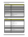
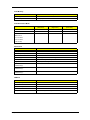
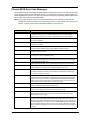
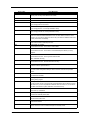
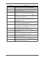
Revision History
Please refer to the table below for the updates made on OpenBook 1848 service guide.
Date
II
Chapter
Updates
OpenBook 1848
Copyright
Copyright © 2004 by AOpen Incorporated. All rights reserved. No part of this publication may be reproduced,
transmitted, transcribed, stored in a retrieval system, or translated into any language or computer language, in
any form or by any means, electronic, mechanical, magnetic, optical, chemical, manual or otherwise, without
the prior written permission of AOpen Incorporated.
Disclaimer
The information in this guide is subject to change without notice.
AOpen Incorporated makes no representations or warranties, either expressed or implied, with respect to the
contents hereof and specifically disclaims any warranties of merchantability or fitness for any particular
purpose. Any AOpen Incorporated software described in this manual is sold or licensed "as is". Should the
programs prove defective following their purchase, the buyer (and not AOpen Incorporated, its distributor, or
its dealer) assumes the entire cost of all necessary servicing, repair, and any incidental or consequential
damages resulting from any defect in the software.
AOpen is a registered trademark of AOpen Incorporated.
Intel is a registered trademark of Intel Corporation.
Pentium and Pentium II/III are trademarks of Intel Corporation.
Other brand and product names are trademarks and/or registered trademarks of their respective holders.
III
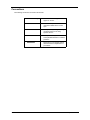
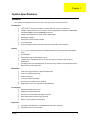
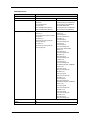
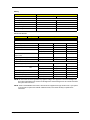
Conventions
The following conventions are used in this manual:
IV
Screen messages
Denotes actual messages that
appear on screen.
NOTE
Gives bits and pieces of additional
information related to the current
topic.
WARNING
Alerts you to any damage that might
result from doing or not doing
specific actions.
CAUTION
Gives precautionary measures to
avoid possible hardware or software
problems.
IMPORTANT
Reminds you to do specific actions
relevant to the accomplishment of
procedures.
OpenBook 1848
Preface
Before using this information and the product it supports, please read the following general information.
1.
This Service Guide provides you with all technical information relating to the BASIC CONFIGURATION
decided for AOpen "global" product offering. To better fit local market requirements and enhance product
competitiveness, your regional office MAY have decided to extend the functionality of a machine (e.g.
add-on card, modem, or extra memory capability). These LOCALIZED FEATURES will NOT be covered
in this generic service guide. In such cases, please contact your regional offices or the responsible
personnel/channel to provide you with further technical details.
2.
Please note WHEN ORDERING FRU PARTS, that you should check the most up-to-date information
available on your regional web or channel. If, for whatever reason, a part number change is made, it will
not be noted in the printed Service Guide. For AOpen AUTHORIZED SERVICE PROVIDERS, your
AOpen office may have a DIFFERENT part number code to those given in the FRU list of this printed
Service Guide. You MUST use the list provided by your regional Xplore office to order FRU parts for repair
and service of customer machines.
V
VI
OpenBook 1848
Table of Contents
Chapter 1
System Specifications
1
Features . . . . . . . . . . . . . . . . . . . . . . . . . . . . . . . . . . . . . . . . . . . . . . . . . . . . . . . .1
System Block Diagram . . . . . . . . . . . . . . . . . . . . . . . . . . . . . . . . . . . . . . . . . . . . .3
Board Layout . . . . . . . . . . . . . . . . . . . . . . . . . . . . . . . . . . . . . . . . . . . . . . . . . . . .4
Top View . . . . . . . . . . . . . . . . . . . . . . . . . . . . . . . . . . . . . . . . . . . . . . . . . . . .4
Bottom View . . . . . . . . . . . . . . . . . . . . . . . . . . . . . . . . . . . . . . . . . . . . . . . . .5
Outlook View . . . . . . . . . . . . . . . . . . . . . . . . . . . . . . . . . . . . . . . . . . . . . . . . . . . . .6
Top View . . . . . . . . . . . . . . . . . . . . . . . . . . . . . . . . . . . . . . . . . . . . . . . . . . . .6
Left Panel . . . . . . . . . . . . . . . . . . . . . . . . . . . . . . . . . . . . . . . . . . . . . . . . . . .7
Right Panel . . . . . . . . . . . . . . . . . . . . . . . . . . . . . . . . . . . . . . . . . . . . . . . . . .8
Rear Panel . . . . . . . . . . . . . . . . . . . . . . . . . . . . . . . . . . . . . . . . . . . . . . . . . .9
Bottom Panel . . . . . . . . . . . . . . . . . . . . . . . . . . . . . . . . . . . . . . . . . . . . . . .10
Indicators . . . . . . . . . . . . . . . . . . . . . . . . . . . . . . . . . . . . . . . . . . . . . . . . . . . . . .11
Lock Keys . . . . . . . . . . . . . . . . . . . . . . . . . . . . . . . . . . . . . . . . . . . . . . . . . . . . . .12
Embedded Numeric Keypad . . . . . . . . . . . . . . . . . . . . . . . . . . . . . . . . . . . . . . . .13
Windows Keys . . . . . . . . . . . . . . . . . . . . . . . . . . . . . . . . . . . . . . . . . . . . . . . . . .14
Hot Keys . . . . . . . . . . . . . . . . . . . . . . . . . . . . . . . . . . . . . . . . . . . . . . . . . . . . . . .15
Launch Keys . . . . . . . . . . . . . . . . . . . . . . . . . . . . . . . . . . . . . . . . . . . . . . . . . . . .16
Hardware Specifications and Configurations . . . . . . . . . . . . . . . . . . . . . . . . . . .17
Chapter 2
System Utilities
31
BIOS Setup Utility . . . . . . . . . . . . . . . . . . . . . . . . . . . . . . . . . . . . . . . . . . . . . . . .31
Navigating the BIOS Utility . . . . . . . . . . . . . . . . . . . . . . . . . . . . . . . . . . . . .32
System Information . . . . . . . . . . . . . . . . . . . . . . . . . . . . . . . . . . . . . . . . . . .33
Main System Settings . . . . . . . . . . . . . . . . . . . . . . . . . . . . . . . . . . . . . . . . .34
Startup Configuration . . . . . . . . . . . . . . . . . . . . . . . . . . . . . . . . . . . . . . . . .36
IDE Primary Master . . . . . . . . . . . . . . . . . . . . . . . . . . . . . . . . . . . . . . . . . . .37
Secondary Master . . . . . . . . . . . . . . . . . . . . . . . . . . . . . . . . . . . . . . . . . . . .38
Onboard Device Configuration . . . . . . . . . . . . . . . . . . . . . . . . . . . . . . . . . .39
System Security . . . . . . . . . . . . . . . . . . . . . . . . . . . . . . . . . . . . . . . . . . . . .40
Boot Options . . . . . . . . . . . . . . . . . . . . . . . . . . . . . . . . . . . . . . . . . . . . . . . . . . . .41
Exit Setup . . . . . . . . . . . . . . . . . . . . . . . . . . . . . . . . . . . . . . . . . . . . . . . . . .42
Chapter 3
Machine Disassembly and Replacement
43
General Information . . . . . . . . . . . . . . . . . . . . . . . . . . . . . . . . . . . . . . . . . . . . . .44
Before You Begin . . . . . . . . . . . . . . . . . . . . . . . . . . . . . . . . . . . . . . . . . . . .44
Disassembly Procedure Flowchart . . . . . . . . . . . . . . . . . . . . . . . . . . . . . . . . . . .45
Removing the Battery . . . . . . . . . . . . . . . . . . . . . . . . . . . . . . . . . . . . . . . . . . . . .47
Removing the Hard Disk Drive Module . . . . . . . . . . . . . . . . . . . . . . . . . . . . . . . .48
Disassembling the Hard Disk Drive Module . . . . . . . . . . . . . . . . . . . . . . . .48
Removing the External DIMM Module . . . . . . . . . . . . . . . . . . . . . . . . . . . . . . . .49
Removing the Modem Board . . . . . . . . . . . . . . . . . . . . . . . . . . . . . . . . . . . . . . .50
Removing the Optical Drive Module . . . . . . . . . . . . . . . . . . . . . . . . . . . . . . . . . .51
Disassembling the Optical Drive Module . . . . . . . . . . . . . . . . . . . . . . . . . .51
Disassembling the Main Unit . . . . . . . . . . . . . . . . . . . . . . . . . . . . . . . . . . . . . . .52
Removing the Hinge Caps . . . . . . . . . . . . . . . . . . . . . . . . . . . . . . . . . . . . .52
Removing the Middle Cover . . . . . . . . . . . . . . . . . . . . . . . . . . . . . . . . . . . .53
Removing the Keyboard Metal Support . . . . . . . . . . . . . . . . . . . . . . . . . . .54
Removing the Keyboard . . . . . . . . . . . . . . . . . . . . . . . . . . . . . . . . . . . . . .54
Removing the RTC Battery . . . . . . . . . . . . . . . . . . . . . . . . . . . . . . . . . . . . .55
Removing the Keyboard Support Bracket . . . . . . . . . . . . . . . . . . . . . . . . . .56
Removing the Antennas . . . . . . . . . . . . . . . . . . . . . . . . . . . . . . . . . . . . . . .57
Removing the Wireless LAN Board . . . . . . . . . . . . . . . . . . . . . . . . . . . . . .58
Removing the LCD Module . . . . . . . . . . . . . . . . . . . . . . . . . . . . . . . . . . . . .59
VII
Table of Contents
Separating the Upper Case from the Lower Case . . . . . . . . . . . . . . . . . . .61
Removing the CPU Heat Sink . . . . . . . . . . . . . . . . . . . . . . . . . . . . . . . . . . .62
Removing the CPU . . . . . . . . . . . . . . . . . . . . . . . . . . . . . . . . . . . . . . . . . . .62
Removing the FDD Module . . . . . . . . . . . . . . . . . . . . . . . . . . . . . . . . . . . . .63
Removing the HDD Guiding Chassis . . . . . . . . . . . . . . . . . . . . . . . . . . . . .63
Removing the VGA Thermal Plate . . . . . . . . . . . . . . . . . . . . . . . . . . . . . . .64
Removing the CPU Thermal Plate . . . . . . . . . . . . . . . . . . . . . . . . . . . . . . .65
Removing the Optical Drive Bracket . . . . . . . . . . . . . . . . . . . . . . . . . . . . . .65
Removing the Main Board . . . . . . . . . . . . . . . . . . . . . . . . . . . . . . . . . . . . .66
Removing the DC Charger Board . . . . . . . . . . . . . . . . . . . . . . . . . . . . . . . .67
Removing the Speakers . . . . . . . . . . . . . . . . . . . . . . . . . . . . . . . . . . . . . . .67
Removing the PCMCIA Slot . . . . . . . . . . . . . . . . . . . . . . . . . . . . . . . . . . . .69
Disassembling the LCD Module . . . . . . . . . . . . . . . . . . . . . . . . . . . . . . . . . . . . .70
Removing the LCD Bezel . . . . . . . . . . . . . . . . . . . . . . . . . . . . . . . . . . . . . .70
Removing the Inverter Board . . . . . . . . . . . . . . . . . . . . . . . . . . . . . . . . . . .71
Removing the LCD . . . . . . . . . . . . . . . . . . . . . . . . . . . . . . . . . . . . . . . . . . .72
Removing the LCD Hinges . . . . . . . . . . . . . . . . . . . . . . . . . . . . . . . . . . . . .73
Removing the LCD Coaxial Cable . . . . . . . . . . . . . . . . . . . . . . . . . . . . . . .73
Chapter 4
Troubleshooting
75
System Check Procedures . . . . . . . . . . . . . . . . . . . . . . . . . . . . . . . . . . . . . . . . .76
Power System Check . . . . . . . . . . . . . . . . . . . . . . . . . . . . . . . . . . . . . . . . .76
Touchpad Check . . . . . . . . . . . . . . . . . . . . . . . . . . . . . . . . . . . . . . . . . . . . .76
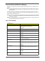
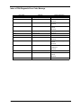
Phoenix BIOS Error Code Messages . . . . . . . . . . . . . . . . . . . . . . . . . . . . . . . . .77
Power-On Self-Test (POST) Error Message . . . . . . . . . . . . . . . . . . . . . . . . . . .80
Index of Error Messages . . . . . . . . . . . . . . . . . . . . . . . . . . . . . . . . . . . . . . .80
Index of Symptom-to-FRU Error Message . . . . . . . . . . . . . . . . . . . . . . . . . . . . .82
Index of PQA Diagnostic Error Code, Message . . . . . . . . . . . . . . . . . . . . .86
Chapter 5
Jumper and Connector Locations
87
Top View . . . . . . . . . . . . . . . . . . . . . . . . . . . . . . . . . . . . . . . . . . . . . . . . . . . . . . .87
Bottom View . . . . . . . . . . . . . . . . . . . . . . . . . . . . . . . . . . . . . . . . . . . . . . . . . . . .89
Chapter 6
FRU (Field Replaceable Unit) List
91
Exploded Diagram . . . . . . . . . . . . . . . . . . . . . . . . . . . . . . . . . . . . . . . . . . . . . . .92
Appendix A
Test Compatible Components
103
Microsoft Windows XP Environment Test . . . . . . . . . . . . . . . . . . . . . . . . . . . . .104
Index
107
VIII
OpenBook 1848
Chapter 1
System Specifications
Features
This computer was designed with the user in mind. Here are just a few of its many features:
Performance
T
Intel® Pentium® 4 Processor 2.26GHz to 3.2GHz CPU with on-die L2 512KB cache
T
128MB to 1GB System memory, with system memory upgradeable to 2GB with two DDR DIMM
slots (DDR 266MHz: PC2100/ DDR333MHz: PC2700)
T
512KB FLASH BIOS with boot block, shadow RAM support.
T
Dual display capability
T
High-capacity, Enhanced-IDE hard disk
T
Li-Ion battery pack
T
Power management system with ACPI (Advanced Configuration Power Interface)
T
14.1” or 15.0” Thin-Film Transistor (TFT) eXtended Graphics Array (XGA) liquid crystal-display
(LCD)
T
3D capabilities
T
Simultaneous LCD and CRT display support
T
Supports other output display devices such as LCD projection panels for large-audience
presentations
T
LCD display with CCFT backlight which can be turned off by software. CCFT backlight has AutoDIM function to extend battery life.
Display
Multimedia
T
Audio codec supports stereo at 18-bit ADC/20-bit DAC
T
AC’97 2.2-compliant stereo audio
T
S-video out put port
T
Line-out jack share with SPDIF
T
Enhanced audio system with two speakers
T
DVD/CD-RW combo drive, CD-ROM or DVD-ROM drive
Connectivity
T
High-speed fax/data modem port
T
USB (Universal Serial Bus) ports
T
Onboard PCI 10/100 BaseT LAN support on board
T
802.11a/b/g wireless with Wi-Fi logo (optional)
T
Wake-on-ring and Wake-on-LAN support
Expansion
Chapter 1
T
CD-ROM or DVD-ROM drive, and DVD/CD-RW combo drive (optional)
T
Upgradeable memory and hard disk
1
T
IEEE 1394 port
T
One Type II/I or Type III CardBus PC Card slot
T
Secure digital (SD)/ Memory Stick/ Multi Media Card (MMC) 3-in-1 slot
Keyboard and Pointing Device
T
84-/85-/88-key IBM PC/AT keyboard, with 4 programmable easy launch keys; one wireless button,
one power button, one Internet browser button, and one E-Mail button
T
Ergonomically-centered touchpad pointing device with 2 buttons and 4-way scroll key
T
Two Type II/I CardBus PC Card slots
T
One RJ-45 jack for 10/100BaseT LAN
T
One RJ-11 56 Kbps fax/modem jack
T
One DC-in jack (AC adapter)
T
TV-out (7 pins) jack
T
One VGA port for external monitor port
T
One audio line-in/microphone-in jack
T
One audio speaker/line-out jack (SPDIF)
T
One FIR port
T
One parallel port
T
Four USB 2.0 ports
T
One IEEE 1394 port
T
Secure Digital (SD)/ Memory Stick/ Multi Media Card 3-in-1 slot
I/O Ports
2
OpenBook 1848
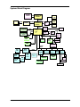
System Block Diagram
Clock Gen
ICS952013
200MHz
DeskTop CPU
CRT
CONN
Northwood
FSB
400/533/800MHz
DDR*2
DDR Buffer
ICS93772
2.5V/400MHz
Primary IDE
HDD ATA-133
2.5V/400MHz
Sis M661FX
Host/Memory
Controller
133MHz
Secondary IDE
CD-ROM
1394
RJ45
ICS1893
CONN
PHY Agere
1394
CONN
400Mb
FW802A
1000Mb
Giga LAN
BCM-5705M
PCI BUS
33MHz
Thermal
G768D
USB*4
DUAL LVDS
PHY
SiS963
MuTIOL
Media
I/O
302LV
LCD
MuTIOL 133MHz
16bit/1GBs
MII
133MHz
TV
CONN
Sis
DVB
Mini PCI
802.11A/B/G
(Dummy)
CardBus
SLOT-A
ENE
CB1420
SLOT-B
USB 1.1/2.0
Power Switch
LPC BUS
33MHz
RJ11
Modem
Controller
CONN
AC’97
Line-In
Mic-In
CODEC
ALC203
AMP
Line-Out
S/PDIF
CP2216/G571S1
AC-LINK
KBC
M38859
LPC ROM
Card Reader
SST 49LF004B
W83L518
MP3 Player
OZ263
Touch Pad
Debug
Port
SIO
NS87392
FIR
SD/MS/MMC
CONN
Floppy
G1420
Internal KB
Serial Port
Parallel Port
Chapter 1
3
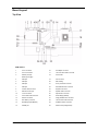
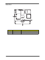
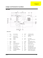
Board Layout
Top View
PCB: 03241-1
1
Line-in connector
16
AC adapter connector
2
Line-out connector
17
Lid cover switch cable connector
3
Modem port (left)
18
CPU socket
19
Fan connector
Network port (right)
4
4
USB port
5
USB port
20
SW1 Setting
6
USB port
21
Touch pad cable connector
7
USB port
22
Hard Diskette Drive connector
8
Inverter cable connector
23
Keyboard connector
9
External monitor port
24
Speaker cable connector
10
TV-out connector
25
Optical drive connector
11
LCD coaxial cable connector
26
South Bridge (SiS963)
12
Mini-PCI connector
27
Floppy diskette drive connector
13
RTC battery connector
28
Launch board cable connector
14
North Bridge (SiS M661FX)
29
PCMCIA cardbus connector
15
Parallel port
30
Golden Finer (Debug Board)
OpenBook 1848
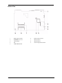
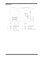
Bottom View
1
Modem cable connector
6
Modem board connector
2
SD/MS/MMC 3-in-1 slot
7
Memory socket 1
3
1394 connector
8
Memory socket 2
4
FIR
9
DC-DC charge board connector
5
CardBus ENE CB1420
Chapter 1
5
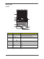
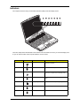
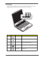
Outlook View
Top View
Number
6
Item
Description
1
Display screen
Also called LCD (liquid-crystal display), displays computer output.
2
Status indicators
LEDs (light-emitting diode) that turn on and off to show the status
of the computer, its functions and components.
3
Launch keys
Buttons for launching frequently-used programs.
4
Power button
Turns on the computer power.
5
Keyboard
Inputs data into your computer.
6
Touchpad
Touch-sensitive pointing device which functions like a computer
mouse.
7
Click buttons (left, right, and
center)
The left and right buttons function like the left and right mouse
buttons.
8
Palm rest
Comfortable support area for your hands when you use the
computer.
9
Fan grill
Cools the CPU by pulling in cool air.
OpenBook 1848
Left Panel
Number
1
Chapter 1
Item
Description
PC card slots
Accepts two TypeII/I CardBus PC card.
2
PC card eject button
Ejects the PC card from its slot.
3
3-in-1 slot media slot
Accepts any of the following flash memory cards; Secure Digital
(SD), Memory Stick, MultiMedia Card (MMC).
4
IEEE 1394
Connects to an IEEE 1394-compatible device (e.g., digital video
camera).
5
Infrared port
Interfaces with infrared devices (e.g., infrared printer, IR-aware
computer).
6
Optical drive activity
indicator
Lights up when the optical drive is active.
7
Eject button
Ejects the CD/DVD tray.
8
Emergency eject slot
Ejects the optical drive tray when the computer is turned off.
9
Optical drive
Internal optical drive (CD, DVD, or DVD/ CD-RW combo drive).
10
Speaker
Outputs sound
7
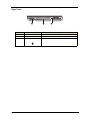
Right Panel
Number
8
Item
Description
1
Speaker
Outputs sound.
2
Floppy drive
Internal diskette drive, accepts 3.5-inch floppy diskettes.
3
Security keylock
Connects to a Kensington-compatible computer security lock.
OpenBook 1848
Rear Panel
Number
Chapter 1
Item
Description
1
DC-in jack
Connects to an AC adapter.
2
Parallel port
Connects to a parallel device (e.g., parallel printer).
3
S-video out port
Connects to a television or display device with Svideo input.
4
External monitor port
Connects to a display monitor (up to 2048x1536
resolution).
5
USB (2.0) ports (four)
Connects to USB devices (e.g., USB digital
camera).
6
Network jack
Connects to an Ethernet 10/100-based network.
7
Modem jack
Connects a phone line (only for models with an
internal fax/data modem).
8
S/PDIF line-out jack
Connects to audio line-out devices (e.g., speakers,
headphones); supports S/PDIF connection.
9
Line-in jack
Accepts audio line-in devices (e.g., audio CD
player, stereo walkman)
9
Bottom Panel
Number
10
Item
Description
1
Memory compartment cover
Houses the computer’s main memory.
2
Battery pack
Supplies power to the computer.
3
Battery release latch
Unlatches the battery to remove the battery pack.
OpenBook 1848
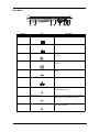
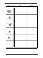
Indicators
The computer has seven easy-to-read status indicators (LEDs) under the display screen.
The Power, Sleep status and Wireless Communication icons are visible even when you close the display cover
so you can see the status of the computer while the cover is closed.
Number
Icon
Function
Description
1
Wireless Communication
Lights when the Wireless LAN capability
(optional) is enabled.
2
Power
Lights when the computer is on.
3
Sleep
Blinks when computer enters Hibernation mode.
Lights when computer enters Standby mode.
Chapter 1
4
Media Activity
Lights when the hard disk, or Media drive is
active.
5
Battery Charge
Lights when the battery is being charged.
6
Caps Lock
Lights when Caps Lock is activated.
7
Num Lock
Lights when Num Lock is activated.
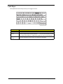
11
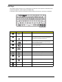
Lock Keys
The keyboard has three lock keys which you can toggle on and off.
Lock Key
When Caps Lock is on, all alphabetic characters typed are in uppercase.
Num Lock
When Num Lock is on, the embedded keypad is in numeric mode. The keys function as a
calculator (complete with the arithmetic operators +, -, *, and /). Use this mode when you need
to do a lot of numeric data entry. A better solution would be to connect an external keypad.
(Fn-F11)
Scroll Lock
(Fn-F12)
12
Description
Caps Lock
When Scroll Lock is on, the screen moves one line up or down when you press the up or down
arrow keys respectively. Scroll Lock does not work with some applications.
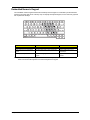
OpenBook 1848
Embedded Numeric Keypad
The embedded numeric keypad functions like a desktop numeric keypad. It is indicated by small characters
located on the upper right corner of the key caps. To simplify the keyboard legend, cursor-control key symbols
are not printed on the keys.
Desired Access
Num Lock On
Num Lock Off
Number keys on embedded keypad
Type numbers in a normal manner.
Cursor-control keys on embedded
keypad
Hold Shift while using cursor-control keys.
Hold Fn while using cursorcontrol keys.
Main keyboard keys
Hold Fn while typing letters on embedded
keypad.
Type the letters in a normal
manner.
NOTE: If an external keyboard or keypad is connected to the computer, the Num Lock feature automatically
shifts from the internal keyboard to the external keyboard or keypad.
Chapter 1
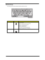
13
Windows Keys
The keyboard has two keys that perform Windows-specific functions.
Key
Windows logo key
Icon
Description
Start button. Combinations with this key perform shortcut functions. Below
are a few examples:
Windows + Tab (Activates next task bar button)
Windows + E (Explores My Computer)
Windows + F (Finds Document)
Windows + M (Minimizes All)
Shift + Windows + M (Undoes Minimize All)
Windows + R (Displays the Run...dialog box)
Application key
14
Opens the application’s context menu (same as a right-click).
OpenBook 1848
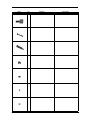
Hot Keys
The computer employs hot keys or key combinations to access most of the computer’s controls like screen
contrast and brightness, volume output and the BIOS Utility.
To activate hot keys, press and hold the Fn key before pressing the other key in the hot key combination.
Hot Key
Icon
Function
Description
Fn-l
Hot key help
Displays a list of the hotkeys and their functions.
Fn-m
Sleep
Puts the computer in Sleep mode, which can be defined
via the advanced section of the Power Management
Properties in the Windows Control Panel.
Fn-n
Display toggle
Switches display output between the display screen,
external monitor (if connected) and both the display
screen and external monitor.
Fn-o
Screen blank
Turns the display screen backlight off to save power.
Press any key to return.
Fn-p
Speaker on/off
Turns the speakers on and off; mutes the sound.
Home
Functions as the “Home” key.
End
Functions as the “End” key.
Fn-x
Brightness up
Increases the screen brightness.
Fn-z
Brightness down
Decreases the screen brightness.
Volume up
Increases the volume.
Volume down
Decreases the volume.
Fn-{
Fn-}
g
d
Fn-w
Volume up
Fn-y
Volume down
Chapter 1
15
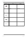
Launch Keys
Located on the left of the keyboard are five buttons. These buttons are called launch keys. They are
designated as Wireless Communication, E-mail, Internet Browser, P1 and P2 buttons.
Number
16
Icon
Function
Description
1
E-mail
The mail button is used to launch the E-mail application.
2
Internet browser
By default, is used to launch your Internet browser.
3
TV out
Automatically switches the display to output on a television
that is connected to the s-video port.
4
Resolution
Launches the resolution setting.
5
Wireless
communication
This button is used to enable or disable the wireless LAN
(optional) function.
OpenBook 1848
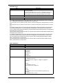
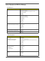
Hardware Specifications and Configurations
Processor
Item
Specification
CPU type
Intel® Pentium® 4
CPU package
P478 package
CPU core voltage
1.5V
CPU I/O voltage
1.2V
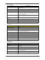
BIOS
Item
Specification
BIOS vendor
Phoenix
BIOS Version
R01-AXX
BIOS ROM type
LPC Flash
BIOS ROM size
512KB
BIOS package
PLCC 32-pin
Supported protocols
ACPI 1.0b/2.0, PCI 2.2, HDD password, INT 15h Extensions, PnP BIOS
1.0a, SM BIOS 2.3, Simple Boot Flag 1.0, Boot Block, USB Specification
1.1/2.0, DTMP Desktop Management Interface Specification V2.0, CDROM Boot Specification V1.0, WfM 2.0 (for build in Ethernet Model),
PCMCIA V3.0 Compliant Device, IEEE 1394 V1.0,
BIOS password control
See SW1 setting.
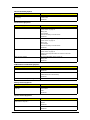
Second Level Cache
Item
Specification
Cache controller
Built-in CPU
Cache size
512KB
1st level cache control
Always enabled
2st level cache control
Always enabled
Cache scheme control
Fixed in write-back
System Memory
Item
Specification
Memory controller
SiS M661FX
Onboard memory size
0MB
DIMM socket number
2 sockets (2 banks)
Supports memory size per socket
128MB, 256MB, 512MB, 1GB
Supports maximum memory size
2048MB
Supports DIMM type
DDR
Supports DIMM Speed
200/ 266/ 333 MHz
Supports DIMM voltage
2.5V
Supports DIMM package
200-pin soDIMM
Memory module combinations
You can install memory modules in any combinations as long as they
match the above specifications.
Chapter 1
17
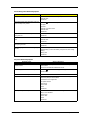
LAN Interface
Item
Specification
Chipset
PHY ICS1893
Supports LAN protocol
10/100 Mbps or Giga LAN
LAN connector type
RJ45
LAN connector location
Rear side
Modem Interface
Item
Specification
Chipset
SiS 963
Fax modem data baud rate (bps)
14.4K
Data modem data baud rate (bps)
56K
Supports modem protocol
V.92 MDC
Modem connector type
RJ11
Modem connector location
Rear side
Floppy Disk Drive Interface
Item
Specification
Vendor & Model Name
PANASONIC JU-226A033
Capacity (MFM)
Recording Density
1MB
1.6MB
Data Transfer Rate
(Kbit/sec)
250
500
Number of Head
2
Track Used
160
Track Density
135
Recording Method
Motor Specification
2MB
FM/MFM
Disk Revolution
(rpm)
300
LSV (%)
+-1.5 (MAX)
360
300
(long-period speed
variation)
LSV (%)
+-2.0 (MAX)
(Instantaneous
speed variation)
Disk Insertion and
Ejection
Drive Motor Starting
Time (msec)
400 (MAX)
1 Track Seek Time
(msec)
3 (MIN)
Settling Time
(msec)
15 (MAX)
Insertion
800 (MAX)
Ejection
1400 (MAX)
Power Requirement
Maximum Voltage Tolerance (V)
18
+5V+-10%
OpenBook 1848
Hard Disk Drive Interface
Item
Specification
Vendor & Model Name
Hitachi
Capacity (MB)
30G
DK23EA-30
Bytes per sector
512
Data heads
2
Recording zone
16
Drive Format
Disks
1
Spindle speed (RPM)
4200 RPM
Performance Specifications
Buffer size
2048KB
Interface
ATA-5 (IDE)
Max. media transfer rate (disk-buffer,
Mbytes/s)
19.4 ~ 37.1
Data transfer rate (host~buffer,
Mbytes/s)
16.6 MB/Sec.
(PIO Mode 4/Multiword DMA Mode 2)
100 MB/Sec.
(Ultra DMA Mode 5)
DC Power Requirements
Voltage tolerance
5V(DC) +/- 5%
CD-ROM Interface
Item
Vendor & Model Name
Specification
Mitsumi SR-244W1
Performance Specification
Transfer rate
Read Sustained:
1545~3600 KB/sec
Programmed I/O:
16.7 MB/sec Max. (Mode 0~4)
Multi-word DMA:
16.7 MB/sec Max. (Mode 0~2)
Ultra DMA:
33.3MB/sec Max.
Access time (typ.)
Random: 115 ms
Full Stroke: 250 ms
Rotation speed
5136 rpm
Data Buffer Capacity
128 KB
Interface
IDE
Applicable disc format
CD/CD-ROM(12cm,8cm), CD-R, CD-RW, CD-DA, CD-ROM (Mode 1,
Mode2), CD-ROM XA (Mode 2, Form1 and Form 2), Photo CD (Single, Multisession), Enhanced CD
Loading mechanism
Drawer with soft eject and emergency eject hole
Power Requirement
Input Voltage
Chapter 1
+5V[DC]+/-5%
19
DVD-ROM Interface
Item
Specification
Vendor & model name
MKE SR-8177 W/K3
Performance Specification
With CD Diskette
With DVD Diskette
Transfer rate (KB/sec)
Average Sustained:
DVD-5:
CAV mode
Normal Speed (1X) 11.08 Mbits/sec
775~1800 blocks/sec
CAV mode 36.67~88.64 Mbits/sec
(10.3X to 24X)
DVD-9/DVD-R/DVD-RW:
1550~3600kBytes/sec (Mode 1)
Normal Speed (1X) 11.08 Mbits/sec
1768~4106 kBytes/sec (Mode 2)
CAV mode 36.67~88.64 Mbits/sec
CD: (Disc: MNSU-005)
DVD-5:(Disc: MKE-D551)
Random (*1)
Random (*4)
120 msec typical
160 msec average max
Average Full Access time (typ.)
CAV mode 95 msec typical 125 msec
average max
Full Stroke (*2)
CAV mode 200 msec typical 260
msec average max
1/3 Stroke (*3)
CAV mode 105 msec typical 135
msec average max
Full Stroke (*5)
270 msec typical
350 msec average max
1/3 Stroke (*6)
130 msec typical
170 msec average max
DVD-9: (Disc: ODSC-PARA)
Random (*7)
150 msec typical
200 msec average max
Full Stroke (*8)
340 msec typical
450 msec average max
1/3 Stroke (*9)
170 msec typical
220 msec average max
DVD-RAM (2.6G) (Disc: LM-DB26)
Random (*10)
200 msec typical
300 msec average max
Full Stroke (*11)
300 msec typical
600 msec average max
Full Stroke (*12)
220 msec typical
320 msec average max
DVD-RAM (4.7G) (Disc: LM-HB47J)
Random (*13)
180 msec typical
300 msec average max
Full Stroke (*14)
320 msec typical
700 msec average max
Full Stroke (*15)
240 msec typical
350 msec average max
20
Data Buffer Capacity
256 kBytes
Interface
IDE
OpenBook 1848
DVD-ROM Interface
Item
Applicable disc format
Specification
DVD: DVD-5, DVD-9, DVD-10, DVD-18, DVD-R (3.95G/4.7G), DVD-RAM
(2.6G/4.7G), DVD-RW
CD: CD-Audio, CD-ROM (mode 1 and mode 2), CD-ROM XA (mode 2, form 1
and form 2), CD-I (mode 2, form 1 and form 2), CD-I Ready, CD-I Bridge,
CD-WO, CD-RW, Photo CD, Video CD, Enhanced Music CD, CD-TEXT
Loading mechanism
Soft eject (with emergency eject hole)
Power Requirement
Input Voltage
+5V[DC]+/-5%
(*1) Average of Data read over the whole area from 00 min. 02 sec. 00 block to 59 min. 58 sec. 74 block more
than 2000 times including latency and layered error correction time.
(*2) From 00 min. 02 sec. 00 block to 59 min. 58 sec. 74 block including latency and layered error correction
time.
(*3) From 00 min. 02 sec. 00 block to 20 min 00 sec. 00 block including latency and layered error correction
time.
(*4) Average of Data read over the whole area from starting data recorded area (LBA:0) to maximum data
recorded area (LBA:23197F), more than 2000 times including latency and layered error correction time.
(*5) From starting data recorded area (LBA:0) to maximum data recorded area (LBA:23197F) including latency
and layered error correction time.
(*6) From starting data recorded area (LBA:0) to maximum data recorded area (LBA:86A29) including latency
and layered error correction time.
(*7) Average of Data read over the whole area from starting data recorded area (LBA:0) to maximum data
recorded area (LBA:3FA0DF), more than 2000 times including latency and layered error correction time.
(*8) From starting data recorded area (LBA:0) to maximum data recorded area (LBA:3FA0DF) including
latency and layered error correction time.
(*9) From starting data recorded area (LBA:0) to maximum data recorded area (LBA:277D8E) including
latency and layered error correction time.
DVD + RW Interface
Item
Vendor & Model name
Specification
Lite-On LSC-24081
Performance Specification
Transfer rate (MB/sec)
Ultra DMA:
33.3 blocks/sec
DMA Mode 2:
33.3 MBytes/sec
PIO Mode 4:
33.3 MBytes/sec
Speed
Writing:
24X (3600KB/Sec) Zone-CLV
(5 Zones, start from 8X, 12X@11min, 16X@21min, 20X@42min,
24X@67min)
Rewriting:
12X (1800KB/Sec) Zone-CLV
(2 Zones, start from 10X, 12X@11min)
Reading:
CD Family:
24X (3600KB/Sec) CAV (4X~24X), DAE Maximum Speed 24X CAV
DVD Family:
8X (10800KB/Sec) CAV (1.7X~8X)
Chapter 1
21
DVD + RW Interface
Item
Access time (typ.)
Specification
Random: DVD 100 ms / CD 95 ms
Full Stroke: 170 ms
Rotation speed
5000 rpm (typ.)
Buffer memory
2MB
Interface
ATA/ ATAPI-5/ MMC-3 and SFF8090 Ver5, Revision 1.2
Applicable disc format
CD-DA, CD-ROM (Mode-1, Mode-2), CD-ROM XA Mode-2 (FORM-1, FORM2), CD-I Ready, Video-CD (MPEG-1), Karaoke-CD, Photo-CD, Enhance CD,
CD extra, I-Trax CD and UFD
PC required
Pentium 166MHz or faster CPU, 64MB DRAM required
HDD must have access time < 29 ms, with a minimum of 100MBytes free
space.
Compatibility
MS-Windows 95/ 98/ ME/ 2000/ XP/ NT4.0
MTBF (Life)
70,000 Hours
Loading mechanism
Drawer with soft eject and emergency eject hole
Power Requirement
Input voltage
5V(DC) +/- 5%
Audio Interface
Item
Audio Controller
Specification
SiS 963
Audio onboard or optional
Built-in
Mono or Stereo
Stereo
Resolution
20 bit stereo Digital to analog converter
18 bit stereo Analog to Digital converter
Compatibility
Microsoft PC98/PC99, AC97 2.1
Mixed sound source
PC speaker, phone line, mic, line-in, CD-in
Voice channel
8/16-bit, mono/stereo
Sampling rate
44.1 KHz
Internal microphone
Yes
Internal speaker / Quantity
Yes
Supports PnP DMA channel
Not available
Supports PnP IRQ
IRQ11
Video Interface
Item
Specification
Chip vendor and model name
SiS M661FX
Chip voltage
Core/1.45V
Memory/2.5V
Supports ZV (Zoomed Video) port
No
Graph interface
Digit Video Link
Maximum resolution (LCD)
14.1” TFT XGA, 1024x768
15.0” TFT XGA, 1024x768
22
Maximum resolution (CRT& LCD)
1024x768x16M colors
Maximum resolution (CRT)
1600X1200
OpenBook 1848
Video Memory
Item
Specification
Fixed or upgradeable
Fixed
Video memory size
64MB (SMA)
Video Resolutions Mode
8 bits
(256 colors)
Resolution
16 bits
(High color)
32 bits
(True color)
640x480
Yes
Yes
Yes
800x600
Yes
Yes
Yes
1024x768
Yes
Yes
Yes
(Maximum for:
14.1” TFT XGA,
15.0” TFT XGA,
External CRT)
Parallel Port
Item
Specification
Parallel port controller
NS SIO PC87392
Number of parallel port
1
Location
Rear side
Connector type
25-pin D-type connector, in female type
Parallel port function control
Enable/Disable by BIOS Setup
Supports ECP/EPP
Yes (set by BIOS setup)
Optional ECP DMA channel
(in BIOS Setup)
DMA channel 1 and 3
Optional parallel port I/O address
(in BIOS Setup)
378, 278, 3BC
Optional parallel port IRQ
(in BIOS Setup)
IRQ7, IRQ5
USB Port
Item
Specification
USB Compliancy Level
1.1/ 2.0
OHCI
1.1/ 2.0
Number of USB port
4
Location
Rear side
Serial port function control
Enable/Disable by BIOS Setup
Chapter 1
23
IrDA Port
Item
Specification
IrDA FIR port controller
NS SIO PC87392
Number of IrDA FIR port
1
Location
Left side
IrDA FIR port function control
Enable/disable by BIOS Setup
IrDA FIR port (in BIOS Setup)
2F8~2EF
IrDA FIR port IRQ (in BIOS Setup)
IRQ3
ECP DMA channel
(in BIOS Setup)
DMA channel 01, 03
Optional IrDA FIR port DRQ (in BIOS
Setup)
Not available
PCMCIA Port
Item
Specification
PCMCIA controller
ENE CB1420
Supports card type
Type-II/I
Number of slots
Two Type -II/I
Access location
Left side
Supports ZV (Zoomed Video) port
No ZV support
Supports 32 bit CardBus
Yes (IRQ11)
System Board Major Chips
Item
System core logic
Controller
Intel SiS M661FX
Intel SiS 963
Super I/O controller
NS PC87392
Audio controller
Intel SiS 963
Video controller
Intel SiS M661FX
Hard disk drive controller
Intel SiS 963
Keyboard controller
Mitsubishi M38857
RTC
Intel SiS 963
Keyboard
Item
24
Specification
Keyboard controller
Mitsubishi M38857
Keyboard vendor & model name
Sunrex K020830A1/UI US
Total number of keypads
84/85/88 international language key (10 languages)
Windows 95 keys
Yes
Internal & external keyboard work
simultaneously
Yes
OpenBook 1848
Battery
Item
Specification
Vendor & model name
Sanyo SI-AS38
Battery Type
Li-Ion
Sony LIPX048
Pack capacity
6600 mAH
6450 mAH
Cell voltage
3.7V/cell
3.7V/cell
Number of battery cell
12
12
Package configuration
4 cells in series, 3 in parallel
4 cells in series, 3 in parallel
Package voltage
14.8 V
14.8V
DC-AC LCD Inverter
Item
Symbol
Vendor & model name
Specification
AMBIT 14/15” T62I194.12
Input Characteristics
Input voltage (VDC)
6.5 (min.)
-
21.0 (max.)
Input current (ADC)
-
-
1 (max.)
Input power (W)
-
-
4.9(max.)
Backlight On/Off control
2.0(min.)
-
3.6(max.)
-0.3(min.)
-
0.8(max.)
-
-
2.56(max.)
Brightness_1 (PWM input)
0 (min.)
3.3 (typ.)
80(max.)
Brightness_2 (DC input)
0(min.)
-
3.0(max.)
On/Off control (mA)
(Input current)
Output Characteristics
Output voltage (Vrms)
-
600 (typ.)
-
Output Current (mArms) Min.
0(min.)
0.6 (typ.)
1.2(max.)
Max.
Frequency (KHz)
5.5(min.)
6.0 (typ.)
6.5(max.)
40(min.)
-
70 (max.)
Output Power (W)
-
-
3.96 (max.)
Burst mode frequency (Hz)
260(min.)
260(typ.)
290 (max.)
Efficiency (%)
80(min.)
-
-
NOTE: DC-AC inverter is used to generate very high AC voltage, then support to LCD CCFT backlight user,
and is also responsible for the control of LCD brightness. Avoid touching the DC-AC inverter area while
the system unit is turned on.
NOTE: There is an EEPROM in the inverter, which stores its supported LCD type and ID code. If you replace
a new inverter or replace the LCD with a different brand, use Inverter ID utility to update the ID
information.
Chapter 1
25
LCD
Item
Vendor & model name
Specification
AU B150XG01 V.2
Hitachi TX38D81VC1CAB
Mechanical Specifications
LCD display area (diagonal, inch)
15
15
Display technology
TFT
TFT
Resolution
XGA
(1024x768)
XGA
(1020x768)
Supports colors
262K
262K
Brightness control
Keyboard hotkey
Keyboard hotkey
Contrast control
No
No
3.3
3.3
Optical Specification
Electrical Specification
Supply voltage for LCD display (V)
AC Adapter
Item
Vendor & model name
Specification
LISHIN 0227A20120
Input Requirements
Maximum input current (A, @90Vac,
full load)
2A
Nominal frequency (Hz)
50-60
Frequency variation range (Hz)
47-63
Input voltage range (Vrms)
90-264
Inrush current
The maximum inrush current will be less than 50A and 100A when the
adapter is connected to 115Vac and 230Vac respectively.
Efficiency
It should provide an efficiency of 83% minimum, when measured at
maximum load under 115Vac.
Output Ratings (CV mode)
DC output voltage
20V
Noise + Ripple
300mVp-pmax (20 MHz bandwidth)
Load
0(min) 6A(max)
Output Ratings (CC mode)
DC output voltage
19.5V~21V for CV mode
Constant current mode
7.0 +/- 0.5A
Dynamic Output Characteristics
Turn-on delay time
2 sec (@ 115Vac)
Hold up time
8ms (@115Vac, Full load)
Over Voltage Protection (OVP)
25V
Short circuit protection
The output can be shorted without damage
Electrostatic discharge (ESD)
15KV (at air discharge)
8KV (at contact discharge)
Dielectric Withstand Voltage
26
Primary to secondary
1500Vac
Leakage current
0.25 mA max. (@ 254Vac, 60Hz)
OpenBook 1848
AC Adapter
Item
Regulatory Requirements
Specification
Safety Requirements:
1.The subject product rated 100-120V 60Hz must be listed under UL 1950
and certified with SCA Standard C22.2 No.950.
2.The subject product rated 200-240V 50Hz must comply with low voltage
directive 73/23EEC.
EMI Requirements:
1.The subject product rated 100-120V 60Hz must meet the EMI
requirements of FCC part 15, Subpart B for Class B Digital Device and get
FCC Certification before marketing into USA and Canada.
2.The subject product rated 200-240V 50Hz must meet the EMC Directive
89/336/EEC.
3.The subject product rated 100-120V must meet the VCCI-2 EMI
requirements.
Power Management
Power Saving Mode
Phenomenon
Standby Mode
T
The Sleep indicator lights up
T
All power shuts off
T
The display shuts off
Waiting time specified by the System
Standby value or the operating system
elapses without any system activity.
Or
When the computer is about to enter
Hibernation mode (e.g., during a battery-low
condition), but the Hibernation file is invalid
or not present.
Hibernation Mode
When customized functions for power
management are set to Hibernation and the
corresponding action is taken.
Display Standby Mode
Keyboard, built-in touchpad, and an external
USB pointing device are idle for a specified
period.
Environmental Requirements
Item
Specification
Temperature
Operating
+5~+35 °C
Non-operating
-10~+60 °C
Non-operating
-30~+60 °C (storage package)
Humidity
Operating
20% to 80% RH, non-condensing
Non-operating
20% to 80% RH, non-condensing (unpacked)
Non-operating
20% to 90% RH, non-condensing (storage package)
Vibration
Operating (unpacked)
2~200Hz: 0.40Grms
Non-operating (unpacked)
2~200Hz: 0.80Grms
Non-operating (packed)
2~200Hz: 1.00Grms
Shock
Chapter 1
27
Environmental Requirements
Item
Operating
Specification
25G/3ms, 10 times
each 4 horizontal directions
35G/3ms, 10 times
each 2 vertical directions
Non-operating
160G/3ms, 1 time
all 6 directions
Mechanical Specification
Item
Dimensions
Specification
326 (W) x 290 (D) x 36.8~38.6 (H) mm
Weight
7.5 lbs for 14.0” TFT model
I/O Por
One type III or two type II/I Cardbus PC Card slot, One RJ-11 phone jack (V.92),
One RJ-45 network jack (Ethernet 10/100), One DC-in jack, One external monitor
port (DDC 2.0), One parallel port, One audio line-out jack (SPDIF) (3.5mm minijack), One audio line-in jack (3.5mm mini-jack), Four USB 2.0 ports, One IEEE
1394 port , One S-video output port, One RJ-45 network jack (Ethernet 10/100)
(option), Secure Digital (SD)/ Memory Stick/ 3-in-1 Card slot, One Fast Infrared
port, FDD.
Drive Bays
Two
Material
Housing: MCS-050
Panel : Plastic
Indicators
Wireless Communication, Power LED, Sleep LED, Media Activity, Battery Charge,
Caps Lock, Num Lock
Switch
Power
Memory Address Map
Memory Address
FF800000-FFFFFFFF
Size
640KB
Function
Firmware hub device
D1000000-D1FFFFFF
640KB
Processor to AGP controller
E0000000-EFFFFFFF
640KB
Processor to AGP controller
00A00000-000BFFFF
640KB
Processor to AGP controller
C0000000-CFFFFFFF
640KB
Processor to AGP controller
FECF0000-FECFFFFF
640KB
Motherboard resources
FED20000-FED8FFFF
640KB
Motherboard resources
000A0000-000BFFFF
640KB
PCI bus
000D0000-000D3FFF
640KB
PCI bus
000D4000-000D7FFF
640KB
PCI bus
000D8000-000DBFFF
640KB
PCI bus
20000000-FEBFFFFF
640KB
PCI bus
000D8000-000DBFFF
640KB
PCI bus
I/O Address Map
I/O Address
28
Function
0000-000F
Direct memory access controller
0081-008F
Direct memory access controller
00C0-00DF
Direct memory access controller
0A79-0A79
ISAPNP read data port
OpenBook 1848
I/O Address Map
I/O Address
Function
0279-0279
ISAPNP read data port
0274-0274
ISAPNP read data port
0062-0062
Microsoft ACPI-compliant Embedded controller
0066-0066
Microsoft ACPI-compliant Embedded controller
0061-0061
System speaker
0040-0043
System timer
0050-0053
System timer
03B0-03BB
Intel(R) processor to AGP controller-2571
03C0-03DF
Intel(R) processor to AGP controller-2571
0000-0CF7
PCI bus
0D00-FFFF
PCI bus
0020-0021
Programmable interrupt controller
00A0-00A1
Programmable interrupt controller
0010-001F
Motherboard resources
0024-0025
Motherboard resources
0028-0029
Motherboard resources
002C-002D
Motherboard resources
0030-0031
Motherboard resources
0034-0035
Motherboard resources
003C-003D
Motherboard resources
0072-0077
Motherboard resources
0080-0080
Motherboard resources
0090-009F
Motherboard resources
00A4-00A5
Motherboard resources
00A8-00A9
Motherboard resources
00AC-00AD
Motherboard resources
00B0-00B5
Motherboard resources
00B8-00B9
Motherboard resources
00BC-00BD
Motherboard resources
1000-107F
Motherboard resources
1180-11BF
Motherboard resources
002E-002F
Motherboard resources
04D0-04D1
Motherboard resourcesr
FE00-FE00
Motherboard resources
0600-060F
Motherboard resources
00F0-00FE
Numeric Data Processor
0070-0071
System CMOS/real time clock
2040-205F
Intel(R) SMBus controller
IRQ Assignment Map
Interrupt Channel
IRQ0
Function
System Timer
IRQ1
Keyboard
IRQ2
Cascade
IRQ3
IR
Chapter 1
29
IRQ Assignment Map
Interrupt Channel
Function
IRQ4
Reserved for PCMCIA R2 Card
IRQ5
Reserved for PCMCIA R2 Card
IRQ6
FDD
IRQ7
LPT (Parallel port)
IRQ8
CMOS/ RTC
IRQ9
SCI IRQ used by ACPI bus
IRQ10
CardBus, SMBUS, IEEE1394, VGA
IRQ11
Audio, Modem, LAN, USB, 802.11B
IRQ13
Math Processor
IRQ14
IDE Primary channel
IRQ15
IDE Secondary channel
DMA Channel Assignment
DMA Channel
30
Function
DRQ1
IrDA FIR
DRQ2
Standard Floppy disk controller
DRQ4
DMA controller
OpenBook 1848
Chapter 2
System Utilities
BIOS Setup Utility
The BIOS Setup Utility is a hardware configuration program built into your computer’s BIOS (Basic Input/
Output System).
Your computer is already properly configured and optimized, and you do not need to run this utility. However, if
you encounter configuration problems, you may need to run Setup. Please also refer to Chapter 4
Troubleshooting when problem arises.
To activate the BIOS Utility, press m during POST
PhoenixBIOS Setup Utility
Information
Main
Advanced
Security
Boot
Exit
CPU Type
Intel® Pentium® 4 CPU 3.00GHz
System Memory
640KB
Extended Memory
xxxxKB
HDD1 Serial Number
xxxxxxxxxxxxxx
System BIOS Version
R01-Axx
VGA BIOS Version
0.82.00
KBC Version
02.13.29
Serial Number
xxxxxxxxxxxxxxxxxxxx
Asset Tag Number
Chapter 2
Product Name
OpenBook 1848
Manufacture Name
Aopen
UUID Number
11807620-2f47-11d8-b39a-xxxxxxxxxxxx
F1 Help
Select Item F5/F6 Change Values
F9 Setup Defaults
Esc Exit
Select Menu Enter Select > Sub-Menu F10 Save and Exit
31
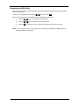
Navigating the BIOS Utility
There are six menu options: System Information, Main System Settings, Advanced, System Security, Boot
Options and Exit Setup.
To enter a menu, highlight the item using the w / y keys, then press e.
Within a menu, navigate through the BIOS Utility by following these instructions:
T
Press the w / y keys to move between the parameters.
T
Press the z
T
Press the | key while you are in any of the menu options to return to the main menu.
/ xkeys to change the value of a parameter.
NOTE: You can change the value of a parameter if it is enclosed in square brackets. Navigation keys are
shown at the bottom of the screen.
32
OpenBook 1848
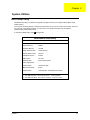
System Information
The System Information screen displays a summary of your computer hardware information.
PhoenixBIOS Setup Utility
Information
Main
Advanced
Security
Boot
Exit
CPU Type
Intel® Pentium® 4 CPU 3.00GHz
System Memory
640KB
Extended Memory
xxxxKB
HDD1 Serial Number
xxxxxxxxxxxxxx
System BIOS Version
R01-Axx
VGA BIOS Version
0.82.00
KBC Version
02.13.29
Serial Number
xxxxxxxxxxxxxxxxxxxx
Asset Tag Number
Product Name
OpenBook 1848
Manufacture Name
Aopen
UUID Number
11807620-2f47-11d8-b39a-xxxxxxxxxxxx
F1 Help
Select Item F5/F6 Change Values
F9 Setup Defaults
Esc Exit
Select Menu Enter Select > Sub-Menu F10 Save and Exit
NOTE: The screen above is a sample and may not reflect the actual data on your computer. “X” may refer to a
series of numbers and/or characters.
The following table describes the information in this screen.
Parameter
Description
CPU Type
Display the CPU type
CPU Speed
Display the CPU Speed.
System Memory
Display the current system memory.
Extended Memory
Display the current extended memory
HDD1 Serial Number
Display the primary master HDD serial number. If no primary master HDD,
show ‘None’.
System BIOS Version
The current system BIOS version
VGA BIOS Version
The current VGA BIOS version. It is got from VGA BIOS AX=5F01h.
KBC Version
The current KBC version.
Serial Number
Display the system serial number. (32 characters)
Asset Tag Number
Display the asset tag number (16 characters)
Product Name
Display the Product Name. (15 characters)
Manufacturer Name
Display the Manufacturer Name (15 characters)
UUID
Display the universally unique identifier of your computer. (16 Byte Hex
digital)
The items in this screen are important and vital information about your computer. If you experience computer
problems and need to contact technical support, this data helps our service personnel know more about your
computer.
Chapter 2
33
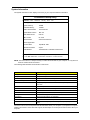
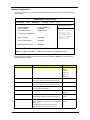
Main System Settings
The Main System Settings screen allows you to set the system date and time.
P h o e n ix B IO S S e tu p U tility
Inform ation
M a in
A d van ced
S ecu rity
S yste m T im e :
[00 :0 0:00 ]
S yste m D a te :
[xx/xx/20 04 ]
B oo t D isplay
[A u to]
S cree n E xp an sio n
[E n ab le d]
Q uick B oo t M o de
[E n ab le d]
B oo t
E x it
Ite m S p ecific H elp
< T a b > , < S h ift-T a b > , o r
<E nter> sele cts field.
B oo t-tim e D iag no stic S cree n [D isa bled ]
B oo t o n LA N
[D isa bled ]
H otk ey B ee p
[E n ab le d]
A uto D im
[E n ab le d]
F 12 M u lti-B oo t
[E n able d]
F 1 H elp
E sc E xit
S elec t Item
S elec t M e nu
F 5/F 6 C h an ge V alu es
F 9 S etup D e fa ults
E n te r S ele ct > S ub -M e nu F 10 S ave an d E xit
The following table describes the parameters in this screen.
.
Parameter
System Time
Description
Sets the system time
Format: HH:MM:SS ( Hour : Minute : Second )
Help: <Tab>,<Shft-Tab>, or <Enter> selects field.
System Date
Sets the system date.
Format: MM/DD/YYYY (Month/Day/Year)
Help: <Tab>, <Shift>, or <Enter> selects field.
Boot Display
Set the display output device on boot up.
Help: Set the display output device on boot up.
When set to Auto, the computer automatically determines the display
device. If an external display device (e.g., monitor) is connected, it
becomes the boot display. When set to Both, the computer outputs to both
the LCD and the external display if one is connected.
Option: Both or Auto
Screen Expansion
Options: Enable or Disable.
QuickBoot Mode
Options: Enable or Disable
Help: Options: Enable or Disable.
Help: Allow the system to skip certain tests while booting. This will
decrease the time needed to boot the system.
Boot-time Diagnostic Screen
Display logo screen during boot
Options: Enable or Disable
Help: Enable to show the Boot-time Diagnostic screen during boot up.
34
OpenBook 1848
Parameter
Boot on LAN
Description
Options: Enable or Disable.
Help: When set to enabled, system will boot on LAN.
Notice: Need to restart system for enabling Boot-on-LAN function.
Hotkey Beep
Options: Enable or Disable
Auto Dimm
Options: Enable or Disable
Help: Enable or disable hotkey beep.
Help: The system will support an automatic dimming of the LCD backlight
when the AC power is NOT available (running on battery power)..
F12 Multi-Boot
Options: Enable or Disable.
Help: Users could choose if to display ‘Fn-F12 for multi-boot’ message
during post
Chapter 2
35
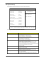
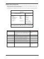
Startup Configuration
The Startup Configuration screen contains parameter values that define how your computer behaves on
system startup.
PhoenixBIOS Setup Utility
Information
Main
Advanced
Security
Boot
Exit
Item Specific Help
Legacy Diskette A
>Primary Master
>Secondary Master
[1.44/1.25 MB 3½”]
[80026MB]
[Optical Drive]
Selects floppy type.
Note that 1.25 MB 3½”
references a 1024
byte/sector Japanese
media format. The
1.25MB, 3½” diskette
requires a 3-mode
floppy-disk drive.
>I/O Device Configuration
Hyper Threading
[Disabled]
Legacy USB Support :
[Enabled]
Default Wireless Device
[Disabled]
F1 Help
Select Item
Esc Exit
Select Menu
F5/F6 Change Values
F9 Setup Defaults
Enter Select>Sub Menu
F10 Save and Exit
The following table describes the parameters in this screen. Settings in boldface are the default and
suggested parameter settings.
Parameter
Legacy Diskette A
Description
Enable or Disable Legacy Diskette A
Options
1.44/1.25MB 3 1/2”
Disabled
360Kb 5 1/4”
1.2MB 5 1/4”
720Kb 3 1/2”
2.88MB 3 1/4”
Primary Master
Show IDE Primary Master Information.
Secondary Master
Show IDE Secondary Master Information
User can enter submenu to set some detail functions
User can enter submenu to set some detail functions.
I/O Device Configuration
Enter submenu to set I/O device configuration
Help: Pheripheral Configuration.
Hyper Threading
Supports on system with Hyper-Threading CPU
Enabled
Disabled
Legacy USB Support
Default Wireless Device
Set Enabled or Disabled USB BIOS Legacy Support.
Enabled
Help: Set Enable support for Legacy Universal Serial
Bus.
Disabled
Select wireless device radio enable by default.
Disabled
Options: [Disabled]: The default state of Wireless LAN
in OS is “Off”.
Enabled
[Last State]:SKeep on the final state “On/Off” of
Wireless LAN when system shut down from OS.
36
OpenBook 1848
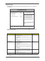
IDE Primary Master
PhoenixBIOS Setup Utility
Advanced
IDE Primary Master
[80026MB]
Item Specific Help
Type:
[Auto]
LBA Format
Total Sectors:
156301488
Maximum Capacity:
80026MB
Multi-Sector Transfers:
LBA Mode Control:
32 Bit I/O:
Transfer Mode:
Ultra DMA Mode:
F1 Help
Esc Exit
Select Item
F5/F6 Change Values
F9 Setup Defaults
Select Menu Enter Select > Sub-Menu F10 Save and Exit
Parameter
Type
[16 Sectors]
[Enabled]
[Disabled]
[Fast PIO 4 / DMA2]
[Mode 5]
User = You enter
parameters of hard-disk
drive installed at this
connection.
Auto = Autotype Hard-Disk
drive installed here.
CD-ROM = A CD-ROM
drive is installed here.
ATAPI Removable =
Removable disk drive is
installed here.
Description
The setting of detail functions stands on type
Help: User = You enter parameters of hard-disk drive
installed at this connection.
Auto = Autotype Hard-Disk drive installed here.
CD-ROM = A CD-ROM drive is installed here.
ATAPI Removable = Removable disk drive is installed
here.
Chapter 2
37
Secondary Master
PhoenixBIOS Setup Utility
Advanced
Secondary Slave
Type:
[Auto]
Multi-Sector Transfers:
LBA Mode Control:
32 Bit I/O:
Transfer Mode:
Ultra DMA Mode:
[Disabled]
[Disabled]
[Disabled]
[FPIO 4 / DMA2]
[Mode 2]
F1 Help
Esc Exit
Description
Type
[Optical Drive]
Item Specific Help
User = You enter
parameters of hard-disk
drive installed at this
connection.
Auto = Autotype Hard-Disk
drive installed here.
CD-ROM = A CD-ROM
drive is installed here.
ATAPI Removable =
Removable disk drive is
installed here.
F5/F6 Change Values
F9 Setup Defaults
Select Item
Select Menu Enter Select > Sub-Menu F10 Save and Exit
Parameter
The setting of detail functions stands on type
Help: User = You enter parameters of hard-disk drive installed
at this connection.
Auto = Autotype Hard-Disk drive installed here.
CD-ROM = A CD-ROM drive is installed here.
ATAPI Removable = Removable disk drive is installed here.
38
OpenBook 1848
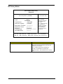
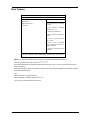
Onboard Device Configuration
The parameters in this screen are for advanced users only. You do not need to change the values in this
screen because these values are already optimized.
The Onboard Device Configuration screen assigns resources to basic computer communication hardware.
P hoenixB IO S S etup U tility
Advanced
I/O D evice C onfiguration
Serial Port B:
M ode:
Base I/O address:
Interrupt:
D M A channel:
[Enabled]
[FIR ]
[2F8]
[IR Q 3]
[D M A 3]
Parallel Port:
M ode:
[Bi-directional]
Item Specific H elp
C onfigure serial port A using
options:
[E nabled]: User
configuration
[D isabled]: No
configuration
[A uto]: B IO S or O S
chooses configuration
(O S C ontrolled): Displayed
when controlled by O S
F1 H elp
Esc Exit
Parameter
Serial Port B
Select Item F5/F6 C hange Values
F9 Setup D efaults
Select M enu Enter Select > Sub-M enu F10 Save and Exit
Description
Options
Enables or disables the infrared port.
Enabled
The infrared port is a PnP device. Enabled/Disabled setting
won’t affect the Windows Device Manager setting of the
infrared port.
Disabled
Mode
Sets operation mode of the serial port B.
FIR, Normal, IrDA, ASK-IR
Base I/O address
Sets the base I/O address, of the parallel port.
3F8, 2F8, 3E8 or 2E8
Help: Set the base I/O address for the serial port B.
Interrupt
Sets the interrupt request of the parallel port.
IRQ 3, IRQ 4
Help: Set the interrupt request for the serial port B.
DMA channel
Sets a DMA channel for the FIR operation
DMA 1 or DMA 3
Help: Set the DMA channel for the FIR of serial port B.
Parallel Port
Enables or disables the Parallel port.
Mode
Sets operation mode of the serial port B.
Bi-directional,
Output only
EPP
ECP
NOTE: When the device is disabled, all the sub-items will be hidden.
Chapter 2
39
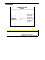
System Security
The System Security screen contains parameters that help safeguard and protect your computer from
unauthorized use.
PhoenixBIOS Setup Utility
Information
Main
Security
Advanced
Set Supervisor Password
Set User Password
[Enter]
[Enter]
Password on boot:
[Enter]
Primary Hard Disk Password
[Enter]
Boot
Exit
Item Specific Help
Supervisor password controls the
access of the whole setup utility.
Only supervisor password was set
then User Password can be set.
If Supervisor Password was cleared
the User Password was cleared,
too.
It can be used on booting system
when
Password-on-boot
was
enabled.
F1 Help
Esc Exit
Select Item
Select Menu
F5/F6 Change Values
Enter Select > Sub-Menu
F9 Setup Defaults
F10 Save and Exit
The following table describes the parameters in this screen. Settings in boldface are the default and
suggested parameter settings.
Parameter
Set Supervisor Password
Description
While entering SETUP, BIOS need to request user to enter
supervisor password if set.
Options
Enter
This password protects the BIOS SETUP menu from
unauthorized entry.
It can be used on booting system when Password-on-boot was
enabled.
This password protects the system from unallowable user entry
before OS boots up.
Set User Password
While entering SETUP, BIOS need to request user to enter
supervisor password if set.
Enter
This password protects the BIOS SETUP menu from
unauthorized entry.
It can be used on booting system when Password-on-boot was
enabled.
This password protects the system from unallowable user entry
before OS boots up
Help: User Password controls access to the system at boot.
Password on boot
During POST, BIOS need to check power on password if set.
Enabled or Disable
This password protects the computer from unauthorized entry
during boot-up.
Help: Enables password entry on boot.
Primary Hard Disk Password Input HDD password
Enter
NOTE: When there is no primary or secondary Hard Disk exist, its Hard Disk Password option should be
hidden.
40
OpenBook 1848
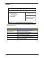
Boot Options
PhoenixBIOS Setup Utility
Information
Main
Advanced
Security
Boot
Exit
Item Specific Help
Optical Drive
+Removable Devices
+Hard Drive
Keys used to view or configure
devices:
<Enter> expands or collapses
devices with a + or <Ctrl+Enter> expands all
<Shift+1>enables or disables a
device.
<+> and<-> moves the device
up or down.
<n>May
move
removable
device between Hard Disk or
Removable Disk
<d>Remove a device that is not
installed.
F1 Help
Esc Exit
Select Item F5/F6 Change Values
F9 Setup Defaults
Select Menu Enter Select > Sub-Menu F10 Save and Exit
NOTE: There are four priorities that can let the user to specify the boot device sequence.
The priority of options from top to down is 1st, 2nd, 3rd, 4th.
If the Removable Device or Hard Drive option has multi devices, show ‘+’ in front of option and show each
device information.
If secondary Hard Disk exists, user can also choose it to Boot. If secondary hard Disk is nonexistence, hide the
secondary Hard Disk option.
Help:
Keys used to view or configure devices:
<Enter> expands or collapses devices with a + or <F5> and <F6> moves the device up or down.
Chapter 2
41
Exit Setup
This menu contains exit options.
PhoenixBIOS Setup Utility
Information Main Advanced
Security
Boot
Exit
Exit Saving Changes
Exit Discarding Changes
Load Setup Defaults
Discard Changes
Save Changes
Item Specific Help
Exit System Setup and save
your changes to CMOS.
F1 Help
Select Item F5/F6 Change Values
F9 Setup Defaults
Esc Exit
Select Menu Enter Select• Sub Menu F10 Save and Exit
The following table describes the parameters in this screen. Setting in boldface are the defaults and
suggested parameter settings.
Parameter
Description
Exit Saving Changes
Save any changes, and exit BIOS setup.
Exit Discarding Changes
Discard any changes, and exit BIOS setup.
Help: Exit System Setup and save your changes to CMOS.
Help: Exit utility without saving Setup data to CMOS.
Load Setup Defaults
Load Setup Defaults.
Discard Changes
Discard any changes.
Help: Load default values for all SETUP items.
Help: Load previous value from CMOS for all SETUP items.
Save Changes
Save changes.
Help: Save Setup data to CMOS.
42
OpenBook 1848
Chapter 3
Machine Disassembly and Replacement
This chapter contains step-by-step procedures on how to disassemble the notebook computer for
maintenance and troubleshooting.
To disassemble the computer, you need the following tools:
T
Wrist grounding strap and conductive mat for preventing electrostatic discharge
T
Flat screwdriver
T
Plastic flat tip tweezers
T
Phillips screwdriver
T
Plastic flat screwdriver
Plastic tweezers
NOTE: The screws for the different components vary in size. During the disassembly process, group the
screws with the corresponding components to avoid mismatch when putting back the components.
T
NOTE: The images are not yet available at this time, once it will be ready this service guide will be revised
accordingly.
Chapter 3
43
General Information
Before You Begin
Before proceeding with the disassembly procedure, make sure that you do the following:
44
1.
Turn off the power to the system and all peripherals.
2.
Unplug the AC adapter and all power and signal cables from the system.
3.
Remove the battery pack.
OpenBook 1848
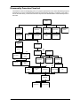
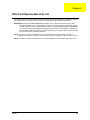
Disassembly Procedure Flowchart
The flowchart on the succeeding page gives you a graphic representation on the entire disassembly sequence
and instructs you on the components that need to be removed during servicing. For example, if you want to
remove the main board, you must first remove the keyboard, then disassemble the inside assembly frame in
that order.
Battery
Bx2
Hinge Caps
HDD Module
Bx1
DIMM Cover
Dx2
Fx2
Middle Cover
HDD
Optical Drive
Module
Modem Cover
HDD Chassis
DIMM
Modem Board
Bx1
Bx1
Keyboard Metal
Support
LCD Coaxial
Cx6
Keyboard
Bx3
RTC Battery
LCD Module
Keyboard Support
Bracket
Upper Case
Ax4
Bx2
Dx4
Antennas
Bx6
Ex4
Cx10
FDD Module
Optical Bracket
CPU Heat Sink
Wireless LAN
Board
Dx2
Speakers
Bx4
CPU Thermal
Plate
HDD Chassis
Dx2
Bx2
VGA Themal Plate
CPU
Bx3
Main Board
Dx4
PCMCIA Slot
Chapter 3
Dx2
DC Charger Board
45
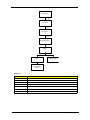
LCD Module
Gx4
LCD Bezel
Gx 1
LCD Inverter
Gx 4
LCD W/Brackets
Gx 2
Hinges
Dx 8
LCD
LCD Brackets
LCD Coaxial
Cable
Screw List
Item
46
Description
A
SCREW M2.5XL4 (SILVER)
B
SCREW M2XL4 Nylok (SILVER)
C
SCREW M2.5XL8 Nylok (BLACK)
D
SCREW M2.0XL3 Nylok (SILVER)
E
SCREW M2.5XL3 Nylok (SILVER)
F
SCREW M3XL4 Nylok (SILVER)
G
SCREW M2.5XL6 Nylok (BLACK)
OpenBook 1848
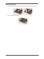
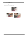
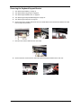
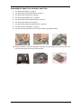
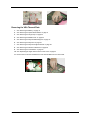
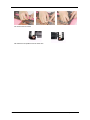
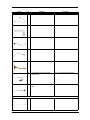
Removing the Battery
1.
Push the battery release button in the arrow direction and push the battery outward from the main unit.
2.
Remove the battery from the system.
Chapter 3
47
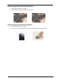
Removing the Hard Disk Drive Module
1.
See “Removing the Battery” on page 47
2.
Pull the plastic tag to detach the HDD module as shown.
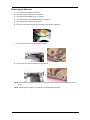
Disassembling the Hard Disk Drive Module
48
1.
See “Removing the Battery” on page 47
2.
Remove the two screws as shown here, and then detach the HDD from the HDD bracket.
OpenBook 1848
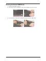
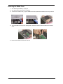
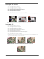
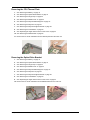
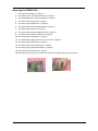
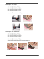
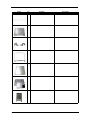
Removing the External DIMM Module
1.
See “Removing the Battery” on page 47
2.
Remove the two screws on the DIMM cover, then remove the DIMM cover from the lower case.
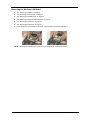
3.
Push out the latches on both sides of the DIMM socket and then remove the DIMM module.
Chapter 3
49
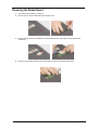
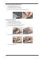
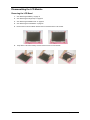
Removing the Modem Board
1.
See “Removing the Battery” on page 47
2.
Remove the one screw and then lift up the modem cover.
3.
Remove the two screws, and detach the modem board from the main board by using a plastic flat
screwdriver.
4.
Disconnect the modem cable from the main board and remove the modem board away.
.
50
OpenBook 1848
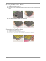
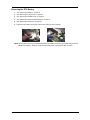
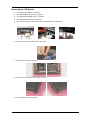
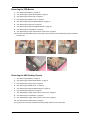
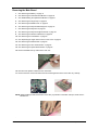
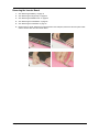
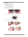
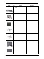
Removing the Optical Drive Module
1.
See “Removing the Battery” on page 47
2.
Remove the one screw, use plastic flat tip tweezers to push the optical drive module out in the direction as
shown.
3.
Gently detach the optical drive module out from the main unit .
Disassembling the Optical Drive Module
1.
See “Removing the Battery” on page 47
2.
See “Removing the Optical Drive Module” on page 51
3.
Remove the two screws and then detach the optical drive holder from the optical drive.
Chapter 3
51
Disassembling the Main Unit
Removing the Hinge Caps
52
1.
See “Removing the Battery” on page 47
2.
Adjust the LCD module to 45 degrees as shown.
3.
Use a plastic flat screwdrier to help detach the hinge caps and remove them from the main unit.
OpenBook 1848
Removing the Middle Cover
1.
See “Removing the Battery” on page 47
2.
See “Removing the Hinge Caps” on page 52
3.
To remove the middle cover, pry up the middle cover with a plastic flat screwdriver in the way as shown
4.
Turn the middle over and put it on the keyboard. Disconnect the launch board cable from the middle
cover.
5.
Remove the middle cover from the main unit.
Chapter 3
53
Removing the Keyboard Metal Support
1.
See “Removing the Battery” on page 47
2.
See “Removing the Hinge Caps” on page 52
3.
See “Removing the Middle Cover” on page 53
4.
Remove the one screw and detach the small keyboard support bracket.
Removing the Keyboard
54
1.
See “Removing the Battery” on page 47
2.
See “Removing the Hinge Caps” on page 52
3.
See “Removing the Middle Cover” on page 53
4.
See “Removing the Keyboard Metal Support” on page 54
5.
Lift the keyboard up and put it on the upper case.
6.
Disconnect the keyboard cable from the main board by using tweezers.
7.
Remove the keyboard away.
OpenBook 1848
Removing the RTC Battery
1.
See “Removing the Battery” on page 47
2.
See “Removing the Hinge Caps” on page 52
3.
See “Removing the Middle Cover” on page 53
4.
See “Removing the Keyboard Metal Support” on page 54
5.
See “Removing the Keyboard” on page 54
6.
Detach the RTC battery and disconnect the RTC cable from the mainboard.
NOTE: Please make sure that you install the RTC battery immediately soon after you uninstall it to prevent the
CMOS from resetting. While you install the RTC battery back, route the RTC cable as shown.
Chapter 3
55
Removing the Keyboard Support Bracket
1.
See “Removing the Battery” on page 47
2.
See “Removing the Hinge Caps” on page 52
3.
See “Removing the Middle Cover” on page 53
4.
See “Removing the Keyboard Metal Support” on page 54
5.
See “Removing the Keyboard” on page 54
6.
Remove the screw, and then disconnect the LCD coaxial cable from the main board. Release the cable
from the clip as shown below.
.
7.
Disconnect the inverter cable from the main board.
.
8.
56
Remove the three screws and then detach the keyboard support bracket from the main unit.
OpenBook 1848
Removing the Antennas
1.
See “Removing the Battery” on page 47
2.
See “Removing the Hinge Caps” on page 52
3.
See “Removing the Middle Cover” on page 53
4.
See “Removing the Keyboard Metal Support” on page 54
5.
See “Removing the Keyboard” on page 54
6.
Disconnect the two RF cables from the sockets on the wireless LAN board.
.
7.
Remove the two screws and detach the left antenna.
8.
Remove the two screws and detach the right antenna.
NOTE: When attaching the antennas back to the upper case, make sure the two RF cables are routed as
shown.
NOTE: Please ignore this step if your notebook is not equipped with antennas.
Chapter 3
57
Removing the Wireless LAN Board
1.
See “Removing the Battery” on page 47
2.
See “Removing the Hinge Caps” on page 52
3.
See “Removing the Middle Cover” on page 53
4.
See “Removing the Keyboard Metal Support” on page 54
5.
See “Removing the Keyboard” on page 54
6.
See “Removing the Antennas” on page 57
7.
Press the latches on both sides of the socket, and then detach the wireless LAN board.
NOTE: Please ignore this step if your notebook is not equipped with wireless LAN board.
58
OpenBook 1848
Removing the LCD Module
1.
See “Removing the Battery” on page 47
2.
See “Removing the Hinge Caps” on page 52
3.
See “Removing the Middle Cover” on page 53
4.
See “Removing the Antennas” on page 57
5.
Remove the one screw and disconnect the coaxial cable from the main board.
6.
Disconnect the inverter cable from the main board.
7.
Remove the four screws as shown.
8.
Remove the two screws from the bottom of the unit.
9.
Lift up and detach the LCD module.
Chapter 3
59
NOTE: When connecting the inverter cable and coaxial cable back to the unit, please note that the two cables
should be routed as shown.
60
OpenBook 1848
Separating the Upper Case from the Lower Case
1.
See “Removing the Battery” on page 47
2.
See “Removing the Optical Drive Module” on page 51
3.
See “Removing the Hinge Caps” on page 52
4.
See “Removing the Middle Cover” on page 53
5.
See “Removing the Keyboard Metal Support” on page 54
6.
See “Removing the Keyboard” on page 54
7.
See “Removing the Keyboard Support Bracket” on page 56
8.
See “Removing the LCD Module” on page 59
9.
Disconnect the touch pad cable, the cover switch cable by using plastic tweezers.
10. Release the fourteen screws from the bottom of the main unit, and the other seven screws as shown and
then remove the upper case from the main unit gently.
Chapter 3
61
Removing the CPU Heat Sink
1.
See “Removing the Battery” on page 47
2.
See “Removing the Hinge Caps” on page 52
3.
See “Removing the Middle Cover” on page 53
4.
See “Removing the Keyboard Metal Support” on page 54
5.
See “Removing the Keyboard” on page 54
6.
See “Separating the Upper Case from the Lower Case” on page 61
7.
Disconnect the fan cable from the main board, remove the four screws on the CPU heat sink, and then
remove the CPU heat sink from the main board.
NOTE: Please follow the order while securing the CPU heat sink with the four screws.
Removing the CPU
1.
See “Removing the Battery” on page 47
2.
See “Removing the Hinge Caps” on page 52
3.
See “Removing the Middle Cover” on page 53
4.
See “Removing the Keyboard Metal Support” on page 54
5.
See “Removing the Keyboard” on page 54
6.
See “Separating the Upper Case from the Lower Case” on page 61
7.
See “Removing the CPU Heat Sink” on page 62
8.
Lift up the CPU lever to release the CPU socket, and then remove the CPU very carefully. Put the CPU
lever back to its original position and have it locked well.
NOTE: To install the CPU, please put it back with the triangle mark this side as shown here.
62
OpenBook 1848
Removing the FDD Module
1.
See “Removing the Battery” on page 47
2.
See “Removing the Optical Drive Module” on page 51
3.
See “Removing the Hinge Caps” on page 52
4.
See “Removing the Middle Cover” on page 53
5.
See “Removing the Keyboard Metal Support” on page 54
6.
See “Removing the Keyboard” on page 54
7.
See “Removing the Keyboard Support Bracket” on page 56
8.
See “Removing the LCD Module” on page 59
9.
See “Separating the Upper Case from the Lower Case” on page 61
10. Disconnect the FDD cable from the main board, remove the two screws and detach the FDD module from
the main unit.
Removing the HDD Guiding Chassis
1.
See “Removing the Battery” on page 47
2.
See “Removing the Optical Drive Module” on page 51
3.
See “Removing the Hinge Caps” on page 52
4.
See “Removing the Middle Cover” on page 53
5.
See “Removing the Keyboard Metal Support” on page 54
6.
See “Removing the Keyboard” on page 54
7.
See “Separating the Upper Case from the Lower Case” on page 61
8.
See “Removing the LCD Module” on page 59
9.
See “Separating the Upper Case from the Lower Case” on page 61
10. See “Removing the FDD Module” on page 63
11. Remove the four screws and detach the HDD guiding chassis from the main board.
Chapter 3
63
Removing the VGA Thermal Plate
1.
See “Removing the Battery” on page 47
2.
See “Removing the Optical Drive Module” on page 51
3.
See “Removing the Hinge Caps” on page 52
4.
See “Removing the Middle Cover” on page 53
5.
See “Removing the Keyboard Metal Support” on page 54
6.
See “Removing the Keyboard” on page 54
7.
See “Removing the Keyboard Support Bracket” on page 56
8.
See “Removing the Wireless LAN Board” on page 58
9.
See “Removing the LCD Module” on page 59
10. See “Separating the Upper Case from the Lower Case” on page 61
11. Remove the four screws and detach the VGA Thermal Plate from the main board.
64
OpenBook 1848
Removing the CPU Thermal Plate
1.
See “Removing the Battery” on page 47
2.
See “Removing the Optical Drive Module” on page 51
3.
See “Removing the Hinge Caps” on page 52
4.
See “Removing the Middle Cover” on page 53
5.
See “Removing the Keyboard Metal Support” on page 54
6.
See “Removing the Keyboard” on page 54
7.
See “Removing the Keyboard Support Bracket” on page 56
8.
See “Removing the LCD Module” on page 59
9.
See “Separating the Upper Case from the Lower Case” on page 61
10. See “Removing the FDD Module” on page 63
11. Remove the one screw and detach the CPU thermal plate from the main unit.
Removing the Optical Drive Bracket
1.
See “Removing the Battery” on page 47
2.
See “Removing the Optical Drive Module” on page 51
3.
See “Removing the Hinge Caps” on page 52
4.
See “Removing the Middle Cover” on page 53
5.
See “Removing the Keyboard Metal Support” on page 54
6.
See “Removing the Keyboard” on page 54
7.
See “Removing the Keyboard Support Bracket” on page 56
8.
See “Removing the LCD Module” on page 59
9.
See “Separating the Upper Case from the Lower Case” on page 61
10. Remove the one screw and detach the CD-ROM bracket from the main unit.
Chapter 3
65
Removing the Main Board
1.
See “Removing the Battery” on page 47
2.
See “Removing the Hard Disk Drive Module” on page 48
3.
See “Disassembling the Optical Drive Module” on page 51
4.
See “Removing the Hinge Caps” on page 52
5.
See “Removing the Middle Cover” on page 53
6.
See “Removing the Keyboard Metal Support” on page 54
7.
See “Removing the Keyboard” on page 54
8.
See “Removing the Keyboard Support Bracket” on page 56
9.
See “Removing the Wireless LAN Board” on page 58
10. See “Removing the LCD Module” on page 59
11. See “Separating the Upper Case from the Lower Case” on page 61
12. See “Removing the FDD Module” on page 63
13. See “Removing the VGA Thermal Plate” on page 64
14. See “Removing the Optical Drive Bracket” on page 65
15. Remove the MMC dummy card from the main unit.
16. Disconnect the speaker cables from the main board.
17. Remove the three screws and detach the main board together from the lower case very carefully.
NOTE: While installing the main board to the lower case, pay attention to the IEEE 1394 port, make sure it’s
installed well.
.
66
OpenBook 1848
Removing the DC Charger Board
1.
See “Removing the Battery” on page 47
2.
See “Removing the Hard Disk Drive Module” on page 48
3.
See “Disassembling the Optical Drive Module” on page 51
4.
See “Removing the Hinge Caps” on page 52
5.
See “Removing the Middle Cover” on page 53
6.
See “Removing the Keyboard Metal Support” on page 54
7.
See “Removing the Keyboard” on page 54
8.
See “Removing the Keyboard Support Bracket” on page 56
9.
See “Removing the Wireless LAN Board” on page 58
10. See “Removing the LCD Module” on page 59
11. See “Separating the Upper Case from the Lower Case” on page 61
12. See “Removing the FDD Module” on page 63
13. See “Removing the VGA Thermal Plate” on page 64
14. See “Removing the Optical Drive Bracket” on page 65
15. See “Removing the Main Board” on page 66
16. Remove the two screws, and detach the DC charger board from the lower case.
Removing the Speakers
1.
See “Removing the Battery” on page 47
2.
See “Removing the Optical Drive Module” on page 51
3.
See “Removing the Hinge Caps” on page 52
4.
See “Removing the Middle Cover” on page 53
5.
See “Removing the Keyboard Metal Support” on page 54
6.
See “Removing the Keyboard” on page 54
7.
See “Removing the Keyboard Support Bracket” on page 56\
8.
See “Removing the LCD Module” on page 59
9.
See “Separating the Upper Case from the Lower Case” on page 61
10. See “Removing the FDD Module” on page 63
11. See “Removing the Optical Drive Bracket” on page 65
12. Release the speaker cables from the lower case.
Chapter 3
67
13. Remove the two screws.
14. Detach the two speakers from the lower case.
68
OpenBook 1848
Removing the PCMCIA Slot
1.
See “Removing the Battery” on page 47
2.
See “Removing the Hard Disk Drive Module” on page 48
3.
See “Disassembling the Optical Drive Module” on page 51
4.
See “Removing the Hinge Caps” on page 52
5.
See “Removing the Middle Cover” on page 53
6.
See “Removing the Keyboard Metal Support” on page 54
7.
See “Removing the Keyboard” on page 54
8.
See “Removing the Keyboard Support Bracket” on page 56
9.
See “Removing the Wireless LAN Board” on page 58
10. See “Removing the LCD Module” on page 59
11. See “Separating the Upper Case from the Lower Case” on page 61
12. See “Removing the FDD Module” on page 63
13. See “Removing the VGA Thermal Plate” on page 64
14. See “Removing the Optical Drive Bracket” on page 65
15. See “Removing the Main Board” on page 66
16. Release the four screws with a screwdriver and detach the PCMCIA slot from the main board.
Chapter 3
69
Disassembling the LCD Module
Removing the LCD Bezel
70
1.
See “Removing the Battery” on page 47
2.
See “Removing the Hinge Caps” on page 52
3.
See “Removing the Middle Cover” on page 53
4.
See “Removing the LCD Module” on page 59
5.
Remove the four screw rubbers and then the four screws from the LCD module.
6.
Snap off the LCD bezel carefully and then remove it from the LCD module.
OpenBook 1848
Removing the Inverter Board
1.
See “Removing the Battery” on page 47
2.
See “Removing the Hinge Caps” on page 52
3.
See “Removing the Middle Cover” on page 53
4.
See “Removing the LCD Module” on page 59
5.
See “Removing the LCD Bezel” on page 70
6.
Remove the one screw, detach the inverter board from the LCD panel, disconnect the LCD power cable
and the inverter cable from the inverter board.
Chapter 3
71
Removing the LCD
72
1.
See “Removing the Battery” on page 47
2.
See “Removing the Hinge Caps” on page 52
3.
See “Removing the Middle Cover” on page 53
4.
See “Removing the LCD Module” on page 59
5.
See “Removing the LCD Bezel” on page 70
6.
See “Removing the Inverter Board” on page 71
7.
Remove the four screws on the hinges as shown.
8.
Detach the LCD together with the LCD brackets from the LCD panel.
9.
Remove the eight screws and then detach the LCD brackets from the LCD.
OpenBook 1848
Removing the LCD Hinges
1.
See “Removing the Battery” on page 47
2.
See “Removing the Hinge Caps” on page 52
3.
See “Removing the Middle Cover” on page 53
4.
See “Removing the LCD Module” on page 59
5.
See “Removing the LCD Bezel” on page 70
6.
See “Removing the Inverter Board” on page 71
7.
Remove the two screws and detach the two hinges from the LCD panel.
Removing the LCD Coaxial Cable
1.
See “Removing the Battery” on page 47
2.
See “Removing the Hinge Caps” on page 52
3.
See “Removing the Middle Cover” on page 53
4.
See “Removing the LCD Module” on page 59
5.
See “Removing the LCD Bezel” on page 70
6.
See “Removing the Inverter Board” on page 71
7.
Remove the tapes, disconnect and remove the coaxial cable from the LCD.
Chapter 3
73
74
OpenBook 1848
Chapter 4
Troubleshooting
Use the following procedure as a guide for computer problems.
NOTE: The diagnostic tests are intended to test only our company’s products. Other brand’s products,
prototype cards, or modified options can give false errors and invalid system responses.
1.
Obtain the failing symptoms in as much detail as possible.
2.
Verify the symptoms by attempting to re-create the failure by running the diagnostic test or by repeating
the same operation.
3.
Use the following table with the verified symptom to determine which page to go to.
Symptoms (Verified)
Go To
Power failure. (The power indicator does not go on or stay
on.)
“Power System Check” on page 76.
POST does not complete. No beep or error codes are
indicated.
“Power-On Self-Test (POST) Error Message” on page 80
POST detects an error and displayed messages on
screen.
“Error Message List” on page 80
Other symptoms (i.e. LCD display problems or others).
“Power-On Self-Test (POST) Error Message” on page 80
Symptoms cannot be re-created (intermittent problems).
Use the customer-reported symptoms and go to “PowerOn Self-Test (POST) Error Message” on page 80
Chapter 4
75
System Check Procedures
Power System Check
To verify the symptom of the problem, power on the computer using each of the following power sources:
1.
Remove the battery pack.
2.
Connect the power adapter and check that power is supplied.
3.
Disconnect the power adapter and install the charged battery pack; then check that power is supplied by
the battery pack.
If you suspect a power problem, see the appropriate power supply check in the following list:
T
“Check the Power Adapter” on page 76
T
“Check the Battery Pack” on page 76
Check the Power Adapter
Unplug the power adapter cable from the computer. If the power-on indicator does not light up, check the
power cord of the power adapter for correct continuity and installation.
If the operational charge does not work, see “Check the Battery Pack” on page 76.
Check the Battery Pack
To check the battery pack, do the following:
From Software:
1.
Check out the Power Management in control Panel
2.
In Power Meter, confirm that if the parameters shown in the screen for Current Power Source and Total
Battery Power Remaining are correct.
3.
Repeat the steps 1 and 2, for both battery and adapter.
4.
This helps you identify first the problem is on recharging or discharging.
From Hardware:
1.
Power off the computer.
2.
Remove the battery pack and measure the voltage between battery terminals 1(+) and 6(ground).
To check the battery charge operation, use a discharged battery pack or a battery pack that has less than 50%
of the total power remaining when installed in the computer.
If the battery status indicator does not light up, remove the battery pack and let it return to room temperature.
Re-install the battery pack.
If the charge indicator still does not light up, replace the battery pack. If the charge indicator still does not light
up, replace the DC/DC charger board.
Touchpad Check
If the touchpad doesn’t work, do the following actions one at a time to correct the problem. Do not replace a
non-defective FRU:
1.
Reconnect the touchpad cables.
2.
Replace the touchpad.
3.
Replace the main board.
After you use the touchpad, the pointer drifts on the screen for a short time. This self-acting pointer movement
can occur when a slight, steady pressure is applied to the touchpad pointer. This symptom is not a hardware
problem. No service actions are necessary if the pointer movement stops in a short period of time.
76
OpenBook 1848
Phoenix BIOS Error Code Messages
The following are the list of messages that Phoenix BIOs can display. Most of them occur during POST. Some
of them display information about a hardware device, e.g., and the amount of memory installed. Others may
indicate a porblem with a device, such as the way it has been configured. The following lists the explanation of
the messages and remedies for reported problems.
NOTE: If your system displays one of the messages marked below with an asterisk (*), write down the
message and contact your dealer. If your system change after you make changes in the Setup menus,
reset the computer, enter Setup and install Seup defaults or correct the error.
Error Codes
0200
Error Messages
Failure Fixed Disk
Fixed disk is not working or not configured properly. Check to see if fixed disk is
attached properly. Run Setup. Find out if the fixed-disk type is correctly identified.
0210
Stuck key
Stuck key on keyboard
0211
Keyboard Error
0212
*Keyboard Controller Failed
Keyboard is not working
Keyboard controller failed test. May require replacing keyboard controller.
0213
Keyboard Locked - Unlock Key Switch
Unlock the system to proceed
0220
Monitor type does not match CMOS - Run Setup
Monitor type not correctly identified on Setup
*0230
Shadow RAM failed at offset: nnnn
*0231
System RAM failed at offset: nnnn
Shadow RAM failed at offset nnnn of in the 64k block at which the error was detected.
System RAM failed at offset nnnn of in the 64k block at which the error was detected.
*0232
Extended RAM failed at offset: nnnn
0250
System battery is dead - Replace and run setup
Extended memory not working or not configured properly at offset nnnn.
The CMOs clock battery indicator shows the battery is dead. Replace the battery and
run Setup to reconfigure the system.
0251
System CMOS checksum bd - Default configuration used
System CMOS has been corrupted or modified incorrectly, perhaps by an application
program that changes data stored in CMOS. The BIOS default installed Default Setup
Values. If you do not want these values, enter Setup and enter your own values. If the
error persists, check the system battery or contact your dealer.
*0260
System Time Error
The timer test failed. Requires repair of system board
*0270
Real Time Clock Error
0271
Check date and time settings
Real-Time Clock fail BIOS hardware test. May require board repair.
BIOS found date or time out of range and reset the Real-Time Clock. May require
setting legal date (1991 - 2099)
0280
Previous Boot Incomplete - Default Configuration used
Previous POST did not complete successfully. POST loads default values and offers to
run Setup. If the failure was caused by incorrect values and they are not corrected, the
next boot will likely fail. On systems with control of wait states, improper Setup settings
can also terminate POST and cause this error on the next boot. Run Setup and verify
that the wait state configuration is correct. This error is cleared the next time the system
is booted.
Chapter 4
77
Error Codes
0281
Error Messages
Memory Size found by POST differed from CMOS
Memory size found by POST differed from CMOS
02B0
Diskette Drive Error
02B1
Diskette Drive B Error
02B2
Incorrect Drive A type - run Setup
02B3
Incorrect Drive B Type - run Setup
Type of floppy drive A: Not correct
Type of floppy Drive A: not correctly identified in Setup.
02B3
Incorrect Drive B Type - run Setup
02D0
System cache error - Cache disabled
Type of floppy drive B: not correctly identified in Setup.
RAM cache failed and BIOS disabled the cache. On older boards, check the cache
jumpers. You may have to replace the cache. See your dealer. A disabled cache slows
system performance considerably.
02F0
CPU ID:
CPU socket number for Multi-Purpose error.
*02F4
EISA CMOS not writeable
Server BIOS 2 test error: Cannot write to EISA CMOS.
*02F5
DMA Test Failed
Server BIOS 2 test error: Cannot write to extended DMA (Direct Memory Access)
registers.
*02F6
Software NMI Failed
Server BIOS 2 test error: Cannot generate software NMI
(Non- Maskable Interrupt)
*02F7
Fail-Safe Timer NMI Failed
Server BIOS 2 test error: Fail-Safe timer takes too long.
Device Address Conflict
Address conflict for specified device
Allocation Error for: device
Run ISA or EISA Configuration Utility to resolve resource conflict for the specified
device.
CD ROM Drive
CD ROM Drive identified
Entering Setup
Starting Setup program
*Failing Bits: nnnn
The hex number nnnn is a map of the bits at the RAM address which failed the memory
test. Each one (1) in the map indicates a failed bit. See errors 230, 231, or 232 above
for offset of the failure in System, Extended, os Shadow memory.
Fixed Disk n
Fixed disk n (0-3) identified.
Invalid System Configuration Data
Problem with NVRAM (CMOS) data.
I/O device IRQ Conflict
I/O device IRQ conflict error
PS/2 Mouse Boots Summary Screen
PS/2 Mouse installed
nnnn KB Extended RAM Passed
Where nnnn is the amount of RAM in kilobytes successfully tested.
78
OpenBook 1848
Error Codes
Error Messages
nnnn Cache SRAM Passed
Where nnnn is the amount of shadow RAM in kilobytes successfully tested.
nnnn KB Shadow RAM Passed
Where nnnn is the amount of shadow RAM in shadow in kilobytes successfully tested.
nnnn KB system RAM Passed
Where nnnn is the amount of shadow RAM in kilobytes successfully tested.
One or more I20 Block Storage Devices were excluded from the Setup Boot Menu.
There was not enough room in the IPL table to display all installed I2O bloc storage
devices.
Operating System Not Found
Operating system cannot be located on either drive A.: or drive C: Enter Setup and see
if fixed disk and drive A are properly identified.
*Parity check 1 nnnn
Parity error found in the system bus. BIOS attempts to locate the address and its
display. Parity is a method for checking errors in binary data. A parity error indicates
that some data has been corrupted.
Parity check 2 nnnn
Parity error found in the I/O bus. BIOS attempts to locate the address and display it on
the screen. If it cannot located the address, it displays????.
Press <F1> to resume, <F2> to Setup, for previous
Displayed after any recoverable error message. Press <F1> to start the boot process or
<F2> to Enter Setup and change the settings. Press <F3> to display the previous
screen (usually an initialization error of an Option ROM, i.e., an add-on card). Write
down and follow the information shown on the screen.
Press <F2> to enter Setup
Optional message displayed during POST. Can be turned off in Setup.
PS/2 Mouse
PS/2 mouse identified
Run the I2O Configuration Utility
One or more unclaimed block storage devices have the Configuration Request bit set in
the LCT. Run an I2O Configuration Utility. (e.g. the SAC Utility)
System BIOS Shadowed
System BIOS copied to shadow RAM
UMB upper limit segment address: nnnn
Displays the address nnnn of the upper limit of Upper Memory Blocks, Indicating
released segments of the BIOS which can be reclaimed by a virtual memory manager.
Video BIOS Shadowed
Video BIOS successfully copied to shadow RAM
Chapter 4
79
Power-On Self-Test (POST) Error Message
The POST error message index lists the error message and their possible causes. The most likely cause is
listed first.
NOTE: Perform the FRU replacement or actions in the sequence shown in FRU/Action column, if the FRU
replacement does not solve the problem, put the original part back in the computer. Do not replace a
non-defective FRU.
This index can also help you determine the next possible FRU to be replaced when servicing a computer.
If the symptom is not listed, The following lists the error messages that the BIOS displays on the screen and
the error symptoms classified by function.
NOTE: Most of the error messages occur during POST. Some of them display information about a hardware
device, e.g., the amount of memory installed. Others may indicate a problem with a device, such as the
way it has been configured.
NOTE: If the system fails after you make changes in the BIOS Setup Utility menus, reset the computer, enter
Setup and install Setup defaults or correct the error.
Index of Error Messages
Error Message List
Error Messages
Failure Fixed Disk
FRU/Action in Sequence
Reconnect hard disk drive connector.
“Load Default Settings” in BIOS Setup Utility.
Hard disk drive
Main Board
Keyboard locked - Unlock key switch
Unlock external keyboard
Monitor type does not match CMOS - Run Setup
Run “Load Default Settings” in BIOS Setup Utility.
Shadow RAM Failed at offset: nnnn
BIOS ROM
Main Board
System RAM Failed at offset: nnnn
DIMM
Main Board
Extended RAM Failed at offset: nnnn
DIMM
Main Board
System battery is dead - Replace and run Setup
Replace RTC battery and Run BIOS Setup Utility to reconfigure
system time, then reboot system.
System CMOS checksum bad - Default
configuration used
RTC battery
System timer error
RTC battery
Run BIOS Setup Utility to reconfigure system time, then reboot
system.
Run BIOS Setup Utility to reconfigure system time, then reboot
system.
Main Board
Real time clock error
RTC battery
Run BIOS Setup Utility to reconfigure system time, then reboot
system.
Main Board
Previous boot incomplete - Default configuration
used
Run “Load Default Settings” in BIOS Setup Utility.
RTC battery
Main Board
Memory size found by POST differed from
CMOS
Run “Load Default Settings” in BIOS Setup Utility.
DIMM
Main Board
80
OpenBook 1848
Error Message List
Error Messages
FRU/Action in Sequence
Diskette drive A error
Check the drive is defined with the proper diskette type in BIOS
Setup Utility
Incorrect Drive A type - run SETUP
Check the drive is defined with the proper diskette type in BIOS
Setup Utility
System cache error - Cache disabled
Main Board
CPU ID:
Main Board
DMA Test Failed
DIMM
Main Board
Software NMI Failed
DIMM
Main Board
Fail-Safe Timer NMI Failed
DIMM
Main Board
Device Address Conflict
Run “Load Default Settings” in BIOS Setup Utility.
RTC battery
Main Board
Allocation Error for device
Run “Load Default Settings” in BIOS Setup Utility.
RTC battery
Main Board
Failing Bits: nnnn
DIMM
BIOS ROM
Main Board
Fixed Disk n
Invalid System Configuration Data
None
BIOS ROM
Main Board
I/O device IRQ conflict
Run “Load Default Settings” in BIOS Setup Utility.
RTC battery
Main Board
Operating system not found
Enter Setup and see if fixed disk and drive A: are properly identified.
Diskette drive
Hard disk drive
Main Board
Chapter 4
81
Index of Symptom-to-FRU Error Message
Error Message List
No beep Error Messages
No beep, power-on indicator turns off and LCD is
blank.
FRU/Action in Sequence
Power source (battery pack and power adapter). See “Power
System Check” on page 76.
Ensure every connector is connected tightly and correctly.
Reconnect the DIMM.
LED board.
Main Board.
No beep, power-on indicator turns on and LCD is
blank.
Power source (battery pack and power adapter). See “Power
System Check” on page 76.
Reconnect the LCD connector
Hard disk drive
LCD inverter ID
LCD cable
LCD Inverter
LCD
Main Board
No beep, power-on indicator turns on and LCD is
blank. But you can see POST on an external
CRT.
Reconnect the LCD connectors.
LCD inverter ID
LCD cable
LCD inverter
LCD
Main Board
No beep, power-on indicator turns on and a
blinking cursor shown on LCD during POST.
No beep during POST but system runs correctly.
Ensure every connector is connected tightly and correctly.
Main Board
Speaker
Main Board
LCD-Related Symptoms
Symptom / Error
LCD backlight doesn't work
Action in Sequence
LCD is too dark
Enter BIOS Utility to execute “Load Setup Default Settings”, then
reboot system.
LCD brightness cannot be adjusted
Reconnect the LCD connectors.
LCD contrast cannot be adjusted
Keyboard (if contrast and brightness function key doesn't work).
LCD inverter ID
LCD cable
LCD inverter
LCD
Main Board
Unreadable LCD screen
Reconnect the LCD connector
Missing pels in characters
LCD inverter ID
Abnormal screen
LCD cable
Wrong color displayed
LCD inverter
LCD
Main Board
LCD has extra horizontal or vertical lines
displayed.
LCD inverter ID
LCD inverter
LCD cable
LCD
Main Board
82
OpenBook 1848
Indicator-Related Symptoms
Symptom / Error
Indicator incorrectly remains off or on, but system
runs correctly
Action in Sequence
Reconnect the inverter board
Inverter board
Main Board
Power-Related Symptoms
Symptom / Error
Power shuts down during operation
Action in Sequence
Power source (battery pack and power adapter). See “Power
System Check” on page 76.
Battery pack
Power adapter
Hard drive & battery connection board
Main Board
The system doesn’t power-on.
Power source (battery pack and power adapter). See “Power
System Check” on page 76.
Battery pack
Power adapter
Hard drive & battery connection board
Main Board
The system doesn’t power-off.
Power source (battery pack and power adapter). See “Power
System Check” on page 76.
Hold and press the power switch for more than 4 seconds.
Main Board
Battery can’t be charged
See “Check the Battery Pack” on page 76.
Battery pack
Main Board
PCMCIA/Smart Card-Related Symptoms
Symptom / Error
Action in Sequence
System cannot detect the PC Card (PCMCIA)
PCMCIA/Smart Card slot assembly
System cannot detect the Smart Card
Smart Card
Main Board
PCMCIA/Smart Card slot assembly
Main Board
PCMCIA/Smart Card slot pin is damaged.
PCMCIA/Smart Card slot assembly
Memory-Related Symptoms
Symptom / Error
Memory count (size) appears different from
actual size.
Action in Sequence
Enter BIOS Setup Utility to execute “Load Default Settings, then
reboot system.
DIMM
Main Board
Speaker-Related Symptoms
Symptom / Error
In Windows, multimedia programs, no sound
comes from the computer.
Action in Sequence
Audio driver
Speaker
Main Board
Internal speakers make noise or emit no sound.
Speaker
Main Board
Chapter 4
83
Power Management-Related Symptoms
Symptom / Error
The system will not enter hibernation
Action in Sequence
Keyboard (if control is from the keyboard)
Hard disk drive
Main Board
The system doesn't enter hibernation mode and
four short beeps every minute.
Press Fn+m and see if the computer enters hibernation mode.
Touchpad
Keyboard
Hard disk connection board
Hard disk drive
Main Board
The system doesn’t enter standby mode after
closing the LCD
LCD cover switch
The system doesn't resume from hibernation
mode.
Hard disk connection board
Main Board
Hard disk drive
Main Board
The system doesn't resume from standby mode
after opening the LCD.
LCD cover switch
Battery fuel gauge in Windows doesn’t go higher
than 90%.
Remove battery pack and let it cool for 2 hours.
Main Board
Refresh battery (continue use battery until power off, then charge
battery).
Battery pack
Main Board
Peripheral-Related Symptoms
Symptom / Error
System configuration does not match the
installed devices.
Action in Sequence
Enter BIOS Setup Utility to execute “Load Default Settings”, then
reboot system.
Reconnect hard disk/CD-ROM/diskette drives.
External display does not work correctly.
Press Fn+n, LCD/CRT/Both display switching
Main Board
USB does not work correctly
Main Board
Print problems.
Ensure the “Parallel Port” in the “Onboard Devices Configuration” of
BIOS Setup Utility is set to Enabled.
Onboard Devices Configuration
Run printer self-test.
Printer driver
Printer cable
Printer
Main Board
Serial or parallel port device problems.
Ensure the “Serial Port” in the Devices Configuration” of BIOS Setup
Utility is set to Enabled.
Device driver
Device cable
Device
Main Board
84
OpenBook 1848
Keyboard/Touchpad-Related Symptoms
Symptom / Error
Keyboard (one or more keys) does not work.
Action in Sequence
Reconnect the keyboard cable.
Keyboard
Main Board
Touchpad does not work.
Reconnect touchpad cable.
Touchpad board
Main Board
Modem-Related Symptoms
Symptom / Error
Internal modem does not work correctly.
Action in Sequence
modem board
Main Board
NOTE: If you cannot find a symptom or an error in this list and the problem remains.
LAN-Related Symptoms
Symptom / Error
Internal LAN does not work correctly.
Action in Sequence
LAN board
Main Board
Wireless LAN-Related Symptoms
Symptom / Error
Internal wireless LAN does not work correctly.
Action in Sequence
right or left antenna kits
wireless LAN board
Main Board
Chapter 4
85
Index of PQA Diagnostic Error Code, Message
Error Code
Message
16XXX
Backup battery error
01XXX
CPU or main board error
Action in Sequence
Backup battery
Reload BIOS default setting.
Main Board
02XXX
Memory error
DIMM
Main Board
03XXX
Keyboard error
Reset Keyboard
Keyboard
Main Board
04XXX
Video error
Main Board
05XXX
Parallel Port error
Main Board
06XXX
Serial port or main board error
Main Board
07XXX
Diskette drive error
Diskette drive
Main Board
08XXX
Hard disk error
Reload BIOS default setting
Hard disk
Main Board
09XXX
CD-ROM error
Reset CD-ROM cable
CD-ROM drive
Main Board
10XXX
Co-processor error
Main Board
11XXX
Pointing device error
Reset Keyboard
Keyboard
Main Board
12XXX
86
Cache test error
Main Board
OpenBook 1848
Chapter 5
Jumper and Connector Locations
Top View
PCB: 03241-1
1
LIN1
Line-in connector
16
DCIN1
AC adapter connector
2
LOUT1
Line-out connector
17
CN2
Lid cover switch cable
connector
3
RJ56
Modem port (left)
18
U20
CPU socket
Network port (right)
4
USB1
USB port
19
FAN1
Fan connector
5
USB2
USB port
20
SW1
SW1 Setting (Please refer to
below)
6
USB3
USB port
21
TPAD1
Touch pad cable connector
7
USB4
USB port
22
HDD1
Hard Diskette Drive connector
8
INV1
Inverter cable connector
23
KB1
Keyboard connector
9
CRT1
External monitor port
24
SPK1
Speaker cable connector
10
TV1
TV-out connector
25
IDE2
Optical drive connector
11
LCD1
LCD coaxial cable connector
26
U61
South Bridge (SiS963)
12
MINI1
Mini-PCI connector
27
FDD1
Floppy diskette drive connector
13
RTC1
RTC battery connector
28
CN4
Launch board cable connector
14
U27
North Bridge (SiS M661FX)
29
CBUS1
PCMCIA cardbus connector
15
PRT1
Parallel port
30
CN3
Golden Finer (Debug Board)
Chapter 5
87
SW1 Settings
ON
88
OFF
Check Password
Enable
Disable
BOOT BLOCK
Enable
Disable
No use
X
X
No use
X
X
Openbook 1848
Bottom View
1
CN1
Modem cable connector
6
MDC1
Modem board connector
2
M_Bay1
SD/MS/MMC 3-in-1 slot
7
DM1
Memory socket 1
3
1394_1
1394 connector
8
DM2
Memory socket 2
4
IR1
FIR
9
CN6
DC-DC charge board connector
5
U36
CardBus ENE CB1420
Chapter 3
89
90
Openbook 1848
Chapter 6
FRU (Field Replaceable Unit) List
This chapter gives you the FRU (Field Replaceable Unit) listing in global configurations of the product. Refer to
this chapter whenever ordering for parts to repair or for RMA (Return Merchandise Authorization).
IMPORTANT: Please note WHEN ORDERING FRU PARTS, that you should check the most up-to-date
information available on your regional web or channel. For whatever reasons a part number change
is made, it will not be noted in the printed Service Guide. For AUTHORIZED SERVICE PROVIDERS,
your office may have a DIFFERENT part number code to those given in the FRU list of this printed
Service Guide. You MUST use the local FRU list provided by your regional office to order FRU parts
for repair and service of customer machines.
NOTE: To scrap or to return the defective parts, you should follow the local government ordinance or
regulations on how best to dispose it, or follow the rules set by your regional office on how to return it.
NOTE: The number indicates the location shown on exploded diagram or “NS” indicates “Not shown” on it.
Chapter 6
91
Exploded Diagram
92
OpenBook 1848
Picture
No.
Partname
Description
Adapter
NS
ADAPTER 3PIN 120W LISHIN
ADPT 3P 120W LISHIN
13
LCD 15” TFT XGA AUO B150XG01 V.2
LCD 15” XGA TFT AU/B150G01 V.2
2
MAINBOARD K3V W/O CPU W/LAUNCH
BOARD CABLE & MODEM & MODEM
CABLE & RTC BATTERY
K3V W/O CPU M/B DIP
NS
DC CHARGE BOARD
K2P DC-DC CHARGER BD-1
NS
TOUCHPAD BOARD
TOUCHPAD SYNAPTICS/TM41PDS357
NS
LAUNCH BOARD
K2P LAUNCH BOARD-1
NS
INVERTER BOARD 14”/15”
INVERTER 14/15” T62I194.12
LCD
Main Board
Boards
Chapter 6
93
Picture
No.
Partname
Description
NS
MODEM BOARD ASKEY
MODEM MDC ASKEY 1456VQL4A(INT)
NS
RTC BATTERY
BATTERY RTC_100MM
NS
BATTERY LI 8CELL 2.2AH SANYO W/O
COVER
ASYBTY PACKLI+8C2.2AHSANYO
NS
COMBO DRIVE 24X LITEON LSC24082KK3/JA
COMBOLITEON/LSC-24082KK3/JA
NS
FDD 1.44 PANASONIC JU-226A033
REV.T
FDD 1.44 PANA/JU-226A033 REV.T
NS
CPU HEATSINK
ASSY CPU HEAT-PIPE
6
VGA THERMAL PLATE
ASSY NB THERMAL PLATE K3V
Battery
COMBO Drive
FDD/FLOPPY Disk Drive
Heat Sink
Cables
94
OpenBook 1848
Picture
No.
Partname
Description
NS
INVERTER CABLE
C.A. INVERTER CABLE YUHINA
NS
FDD CABLE
CABLE FDD FFC
NS
LCD COAXIAL CABLE XGA 15”
CABLE COAXIAL XGA FVC K3U
NS
LAUNCH BOARD CABLE
CABLE LAUNCH K2P
NS
TOUCHPAD CABLE
CABLE TOUCH PAD FPC
NS
COVER SWITCH CABLE 2PIN 50MM
2CONNECTOR
C.A. 2P 2C 50MM SUSPEND SWITCH
NS
MODEM CABLE 2PIN 2CONNECTOR
55MM
WIRE MDC 2CONN 2P 55MM
LCD BRACKET 15” LEFT
BRACKET 15” LCD L K3D
Case/Cover/Bracket Assembly
NS
Chapter 6
95
Picture
96
No.
Partname
Description
NS
LCD BRACKET 15” RIGHT
BRACKET 15” LCD R K3D
NS
LCD PANEL W/HINGE
ASSY PANEL K3V-A
NS
HINGE PACK 15”
HINGE PACK 15”
NS
LCD BEZEL W/ICON PLATE
ASSEMBLY BEZEL 15” K3V-A
NS
FDD BRACKET
BRACKET FDD K3D
NS
CD-ROM SUPPORT BRACKET
ASSY CD-ROM SUPPORT K2P
NS
HDD BRACKET
ASSEMBLY HDD BRACKET K3D
OpenBook 1848
Picture
Chapter 6
No.
Partname
Description
8
MIDDLE COVER W/LAUNCH BOARD &
LOGO
ASSY MIDDLE COVER K3V-A
4
KEYBOARD SUPPORT BRACKET
ASSY NEW KB SUPPORT K2P
1
KEYBOARD BRACKET METAL
METALFIXKBK3D
NS
HINGE CAP RIGHT
CAP R HINGE K3D
NS
HINGE CAP LEFT
CAP L HINGE K3D
9
LOWER CASE W/DIMM COVER &
MODEM COVER & SPEAKER
ASSY LOWER CASE K3V-A
NS
MODEM COVER W/SCREWS
ASSEMBLY MDC DOOR K3D
97
Picture
98
No.
Partname
Description
NS
DIMM DOOR W/SCREW
ASSEMBLY DIMM DOOR K3D
12
UPPER CASE W/COVER SWITCH
CABLE
ASSY UPPER CASE K3V-A
NS
PCMCIA DUMMY CARD
CARDMMCDUMMY
NS
BATTERY COVER
COVERBATTERYK3D
10
HDD CHASSIS
ASSY CHASSIS HDD GUIDE
NS
TOUCHPAD BRACKET
ASSY TOUCH PAD SUPPORT K2P
7
CPU THERMAL PLATE K
ASSY CPU THERMAL PLATE K3V
OpenBook 1848
Picture
No.
Partname
Description
5
OPTICAL BRACKET
BRACKET CD-ROM K3D
NS
DIMM COVER
ASSYDIMMDOORK3V
NS
SPEAKER
SPEAKER YUHINA
Speakers
Chapter 6
99
Picture
No.
Partname
Description
Miscellaneous
NS
SCROLL KEY KNOB
KNOB SCROLL KEY K3V-A
NS
SIDE KEY RIGHT
KNOB SIDE KEY RIGHT K3V-A
NS
SIDE KEY LEFT
KNOB SIDE KEY LEFT K3V-A
NS
LCD SCREW RUBBER
RUBBER LCD CUSHION K3D
NS
LCD SCREW RUBBER
RUBBER LCD SCREW K3D
NS
RUBBER FOOT
RUBBER FOOT LOWER CASE
Screws
100
OpenBook 1848
Picture
Chapter 6
No.
Partname
Description
NS
SCREW
SCRW HEX NYL I#R-40/O#4-40 L5.5
NS
SCREW
SCREW MACH PAN NYLOK M2.0*10 NI
NS
SCREW
SCREW CPU SCREW FORCE 5KGS
NS
SCREW
SCREW M2*3 NYLON 1 JMCPC-420325
NS
SCREW
SCREW M2.5X6
NS
SCREW
SCREW WAFER NYLOK NI 2ML3
NS
SCREW
SCREW M2*4 WAFER NI
101
Picture
102
No.
Partname
Description
NS
SCREW
SCREW M2.5*3 WAFER NI
NS
SCREW
SCREW M2.5*4L NI
NS
SCREW
SCREW M3X4(86.9A524.4R0)
NS
SCREW
SRW M2.5*8L B/ZN NYLOK 700
NS
SCREW
SCREW (86.9A352.4R0)
OpenBook 1848
Appendix A
Test Compatible Components
This computer’s compatibility is tested and verified by the internal testing department. All of its system
functions is tested under Windows XP.
Refer to the following lists for components, adapter cards, and peripherals which have passed these tests.
Regarding configuration, combination and test procedures, please refer to the K3V Compatibility Test Report
released by the Mobile System Testing Department.
Appendix A
103
Microsoft Windows XP Environment Test
Item
Processor
Specifications
P4P 3.0G
P4P 2.6G
Memory (DDR-DIMM)
SDIMM 512MB DDR333 HYS64D6402
SODIMM 256MB HYS64D32020GDL-7-B
LCD
15” XGA TFT N150X3-L05
15” XGA TFT AU/B150XG01
Hard Disk Drive
80GB/TDMT MK8025GAS
60GB/Toshiba MK6021GAS
Basic PC Card List
LAN Card
3Com EtherLink III 3C589D (PEN-050)
IBM EtherJet CardBus Adapter 10/100 (PEN-936)
Intel EtherExpress Pro/100 Mobile Adapter MBLA3200 (PEN-906~910)
Xircom CardBus Ethernet 10/100 32Bit CBE - 10/100BTX (PEN-911~912)
Modem Card
USR Megahertz 56K PC Card Modem (PFM-044)
Xircom CreditCard Modem 56 (PFM-079~081
IBM 56K Double Jack Modem 02K4197 (PFM-059-1~2)
Combo Card
3Com Megahertz 10/100 LAN + 56K Modem PC Card KB-04-002 (PCB041)
Xircom RealPort CardBus Ethernet 10/100 + Modem 56 RBEM5G-100
(PCB-053-054)
ATA Card
IBM MicroDrive 340MB PMR-02-03~04 PMR-036
IBM MicroDrive 1G PMR-051~052
Iomega Click! 40MB PMR 045
Sony Memory Stick 64 MB PMR-062
Sandisk Compact Flash Card 20MB
Apacer SD Flash Card 128MB CARD-05
Apacer 128MB Memory Stick CARD-065
USB 2.0 Card (*1)
Apricorn EZ-USB 2.0 CardBus PC Card (Pen-934)
DTK USB 2.0 Port CardBus Host Controller PUC-102 (Usb-Cb-03 & UsbCb-02)
Adaptec USB 2 Connect Usb-Cb-01)
IOGEAR Cardbus Card PC Card USB 2.0 (USB-CB-05) (USB-CB-06)
1394 Card
Buffalo 1394 Interface CardBus IFC-ILCB/DV (IEEE-01~03)
I-O Data 1394 Interface CardBus CB1394/DVC(IEEE-06~07)
Pixela 1394 CardBus PC Card PIX-PCMC/FW1 (IEEE-04~05)
SCSI Card
Adaptec 1480A or B SCSI CB 1680880A/B (PIO-001~006)
NewMedia Bus Toaster SCSI II (PIO-007~008)
Wireless LAN Card
Intel Pro/Wireless LAN PC Card 2011B (PEN-096)
Proxim Skyline 802.11a Cardbus Card (PEN-937~938)
Cisco Aironet 350 Series Wireless LAN Card (Wireless-011~012)
NeWeb Wireless Lan Card 802.11b (Wireless-013~014)
Cisco Wireless Lan Card 802.11a (Wireless-015~016)
BlueTooth Card
IBM Community Bluetooth PC Card (Bule-04)
Toshiba Bluetooth PC Card PABTC001 (Bule-02)
ISDN
US Robotics Megahertz 128K ISDN Card 405R17T7117M (PIS-002)
IBM ISDN Card 05K3320 (PFM-058)
Token Ring Card
IBM Token ring 16/4 Adapter II (PTR-004~008)
I/O Peripheral
104
OpenBook 1848
Item
I/O - External CRT
Specifications
Acer 211c 21” MT-01~034
ViewSonic PF790, 19” MT-01-039
Acer FP751 17” TFT LCD MT-01-036
IBM Color TFT LCD 14” 9514-B03 (MT-01-028)
Compaq Color Monitor V70 (MT-01-003)
Net Color Monitor 20” MT (01-006)
Mozo 17” TFT LCD (DVI) MT-01-30)
I/O - Projector
NEC MultiSync MT-1040
I/O - Legacy(PS2 / Serial) Keyboard /
Mouse
IBM 101 Key Keyboard KB-454 (KB-01-013)
IBM 109 Key Keyboard 5576-B06 (KB-01-017)
Acer PS2 Keyboard 6311-C4C (KB-01-21~24)
Acer KB-101A GQ87EEKB-101A (KB-01-004)
IBM Numeria KeyPad III 79F6408 (KB-01-016)
IBM Numeric KeyPad (KB-01-016)
Acer Mouse M-S34 (MO-02-003)
IBM PS2 Mini Mouse 07G0033 (MO-02-036)
IBM PS2 Mouse 12J3615 (MO-02-037)
Logitech Cordless MouseMan Wheel PS2 interface (MO-03-057~58)
Logitech Serial Mouse M-M35 (MO-01-031)
Microsoft InteliMouse PS2 interface (MO-02-022)
Microsoft InteliMouse Optical Ps2 interface X05-48796 (MO-03-056)
Logitech First Mouse Three Button Serial Mouse
I/O - Parallel (Printer/Scanner)
Canon BJC-600J (JP OS only) PT-02-005
Epson Stylus Color 740 Parallel Interface PT-02-012
HP DeskJet 890C PT-01-004
HP DeskJet 880C Parallel interface PT-02-013
HP LaserJet 6MP PT-01-015
HP LaserJEt 2200 PT-02-014
I/O - IR Printer
HP LaserJet 6MP use IR PT-01-015
HP LaserJet 2200 use IR PT-02-014
I/O - USB Keyboard/Mouse
Chicony USB Keyboard KU-8933 (KB-04-001~002)
Microsft Natural Keyboard Pro (KB-04-013)
Acer Aspire USB Mouse M-UB48(MO-03-040)
Logitech USB MouseMan Wheel USB interface
Logitech Coreless MouseMan Wheel USB interface (MO-03-058)
Logitech USB Wheel Mouse M-BB48 (MO-03-050)
Microsoft IntelliMouse Optical USB Interface (MO-03-056)
I/O - USB Printer/Scanner
Epson Stylus Color 740 USB interface PT-02-012
HP DeskJet 880C USB interface PT-02-013
Canon CanonScan D1250 (USB 2.0, JP OS only) (SC-009)
HP ScanJet 3300C Color Scanner MY97712194 (SC-01-004)
HP Deskjet 995C (usb interface)
I/O - USB Speaker/Joystick
JS USB Digital Speaker SP-01-017~18
Panasonic USB Speaker EAB-MPC57USB SP-01-023
AIWA Multimedia Digital Speaker SC-UC78 (SP-01-019)
Microsoft Side Winder Precision Pro Joystick 326-00069 (JK-01-002)
Logitech WingMan Rumble Pad G-UA3 (JK-01-010~11)
I/O - USB Camera
Intel Easy PC Camera A20953-001 (CM-01-022)
Logitech QuickCam Express Internet (CM-01-019-2)
Logitech QuickCam Home PC Video Camera VCAM-U1(CM-01-018-2)
Orange Micro USB 2.0 Web Cam (CM-02-04)
Appendix A
105
Item
I/O - USB Storage Drive
Specifications
Logitec CDRW + DVDROM combo USB interface RW-12
Iomega USB Zip 250MB ZIP-01-002
Plextor Burn-proof CDRW (usb 2.0) PX-S88TU CW-03
Fujitsu MO-1300 1.3G (usb 2.0)
Fujitsu 20G HDD (usb 2.0) (*2) t4988618913874 USB-HD-01
Sony DVDROM (usb 2.0) USB-RW-01
IO-Data DVDROM (usb 2.0) USB-RW-02
PQI 6 IN 1 Flash Card Reader/Writer(*1) USB-03-03
Sandisk Card Reader 6 In 1 (Usb 2.0) USB-03-04)
I/O - USB Flash Drive
Apacer USB Handy Drive 32/128MB USB-03-004~008
Apacer USB Handy Driver 256/512MB USB-03-006~010
Sony Memory Key 128MB USB-03-011~012
Dell Memory Key 64MB PMR-069~8
I/O - USB Hub
Belkin 4 Port USB Hub F5u001 HUB -02-015
Eizo I Station USB Hub DH-1401 HUB-02-012~13
Elecom USB Hub 4 Port UH-4S HUB-02-014
Sanwa USB Hub 4 Port HUB-010~011
4 Port Hub (usb 2.0) UH-204 HUB-02-02
Corega Wireless LAN USB Stick11 (usb 1.1) *1 t4988618913874 USB-HD01
I/O - 1394 Storage Drive
Logitec Fireware CDRW + DVD-ROM Combo
I-O Data Fireware HD I.LINK 30GB HAD-130G HD-01-005
VST-Fireware HD FW1260 HD-01-003
Maxtor External Storage 80GB 1394 HDD HD-01-009
Smartdick Firelite Hard Devies for 1394 (*2) HD-01-010~11)
I/O - 1394 Camera
Sony DV DCR-TRV10 CM-01-005
Orange Micro 1394 Web Cam(*1) CM-02-02~03
I/O - 1394 Hub
ADS PYRO 1394 HUB HUB-009
I/O - Access Point 802.11b
Hitachi DC-CN3300 RW-12
Lucent RG-1000 ZIP01-002
Lucent WavePoint-II PX-S88TU CW-03
Cisco Aironet 350 Wireless-010
Orinoco AP-500 Wireless-001
I/O - Access Point 802.11a/b
Intel Dual Pro/Wireless 5000 Wireless-008
I/O - Access Point 802.11a
Intel Pro/Wireless 5000 Wireless-009
I/O - TV (NTSC/PAL)
Sony 29” Trinitron KV-XA29N90
I/O - Bluetooth Device
Sony Ericksson Wireless Headset BLUE-08
HP Deskjet 995C (bluetooth interface) PT-03-016
X Bridge Bluetooth Access Point BT300 PT-03-016
I/O - Multimedia Card
Pretec Multimedia card 64MB PMR-055
Sandisk Multimedia card 32MB PMR - 056~7
I/O - SD Card
Pretec SD card 64MB RW-12
Apacer SD card 128MB RW-12
Transcend SD card 32MB RW-12
I/O - Memory Stick(*1)
Sony MEmory stick 64MB PMR-040~042
Sandisk Memory stick 128MB PMR-059
Apacer Memory stick 128MB PMR-065
I/O - Smart Media(*1*2)
Sandisk Smart media 64MB PMR-069
Apacer Smart media 64MB PMR-066
106
OpenBook 1848
Index
A
on indicator 11
Core logic 24
AC Adapter 26
CPU
ACPI 1.0a 17
core voltage 17
I/O voltage 17
package 17
Removing 62
type 17
APM 1.2 17
Audio 22, 24
B
Battery 25
D
Battery Pack 47
DIMM 17
battery pack
external 49
package 17
removing 49
Speed 17
voltage 17
charging indicator 11
BIOS 17
package 17
password control 17
ROM size 17
ROM type 17
vendor 17
Version 17
Disassembly
Battery Pack 47
LCD Module 59
Machine 43
Procedure Flowchart 45
BIOS Setup Utility 31
BIOS Supports protocol 17
Display 3
BIOS Utility 31
display
Basic System Settings 34
Navigating 32
Startup Configuration 36
System Information 33
hotkeys 15
Display Standby Mode 27
DMA Channel Assignment 30
DVD-ROM Interface 20
Board Layout 4
Bottom View 5
Top View 4
E
Environmental Requirements 27
brightness
Error Messages 80
hotkeys 15
Error Symptoms 82
C
Indicator 83
LCD 82
Memory 83
PCMCIA 83
Power 83
Power Management 84
Speaker 83
Cache
controller 17
size 17
caps lock
on indicator 11
CardBus 24
Error Symptom-to-Spare Part Index 80
Check Procedures 76
Exploded 92
Battery 76
Memory 76
Power Adapter 76
Power System Checkout 76
Touchpad 76
computer
Index
F
Features 1
FIR 24
FRU 91
107
H
PCMCIA 24
PCMCIA Socket
Hard disk 19, 24
Removing 69
Hardware Specifications and Configurations 17
Phoenix BIOS Error Code Messages 77
HDD 19, 24
POST 80
Hibernation Mode 27
Power Management 27
Hibernation mode
Power System Check 76
hotkey 15
Battery Pack 76
Power Adapter 76
Hot Keys 12
Power System Checkout 76
I
Processor 17
I/O Address Map 28
Indicators 11
R
IrDA 24
Removing the 2nd Fan Support Bracket 65
IRQ Assignment Map 29
Removing the CPU Heat Sink 62
Removing the Hard Disk Drive Module 48
J
Removing the HDD Guiding Chassis 63
Jumper and Connector Locations 87
Removing the Keyboard Metal Bracket 54
Top View 87
Removing the Keyboard Metal Support 54
Removing the Keyboard Support Bracket 56
K
Removing the LCD 72
Keyboard 24
Removing the Optical Drive Bracket 65
Removing 54
Removing the RTC Battery 55
RMA 91
L
RTC 24
L2 cache 17
LAN/Modem Combo 18
S
LCD 26
Screw List 46
DC-AC LCD Inverter 25
Second Level Cache 17
speakers
M
hotkey 15
Machine Disassembly 43
Standby Mode 27
Mechanical Specification 28
Super I/O 24
media access
System
on indicator 11
Block Diagram 3
Layout 4
Memory
System Check Procedures 76
Address Map 28
Memory Address Map 28
System Memory 17
Memory Check 76
System Utilities 31
Modem 18
T
P
Temperature 27
Test Compatible Components 103
Panel 6
Bottom 10
left 6
Rear 8
right 8
Parallel Port 23
PC Card 11, 24
108
Touchpad Check 76
Troubleshooting 75
U
USB 23
OpenBook 1848
utility
BIOS 31
V
Video 22, 23
Resolutions 23
Video controller 24
W
Windows XP Environment Test 104
Chapter 3
109
110
OpenBook 1848