1
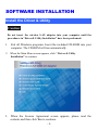
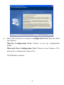
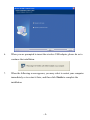
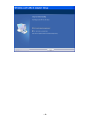
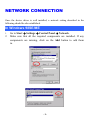
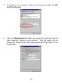
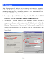
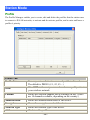
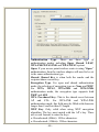
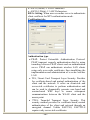
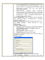
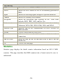
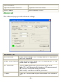
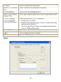
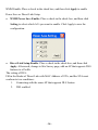
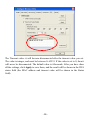
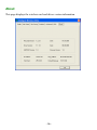
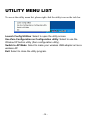
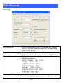
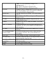
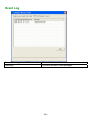
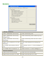
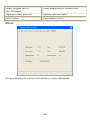
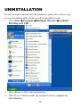
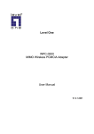
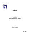
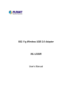
802.11b/g Mini Wireless LAN
USB 2.0 Adapter
User’s Manual
REGULATORY STATEMENTS
FCC Certification
The United States Federal Communication Commission (FCC) and the
Canadian Department of Communications have established certain rules
governing the use of electronic equipment.
Part15, Class B
This device complies with Part 15 of FCC rules. Operation is subject to the
following two conditions:
1) This device may not cause harmful interface, and
2) This device must accept any interface received, including interface that may
cause undesired operation. This equipment has been tested and found to
comply with the limits for a Class B digital device, pursuant to Part 15 of the
FCC Rules. These limits are designed to provide reasonable protection
against harmful interference in a residential installation. This equipment
generates, uses and can radiate radio frequency energy, and if not installed
and used in accordance with the instructions, may cause harmful
interference to radio communications. However, there is no guarantee that
interference will not occur in a particular installation. If this equipment does
cause harmful interference to radio or television reception, which can be
determined by turning off and on, the user is encouraged to try to correct the
interference by one or more of the following measures:
ω Reorient or relocate the receiving antenna.
ω Increase the distance between the equipment and receiver.
ω Connect the equipment into an outlet on a circuit different from that to
which the receiver is connected.
CAUTION:
1) To comply with FCC RF exposure compliance requirements, a separation
distance of at least 20 cm must be maintained between the antenna of this
device and all persons.
2)
This transmitter must not be co-located or operating in conjunction with
any other antenna or transmitter.
Table of Contents
INTRODUCTION ...................................................................................................1
TU
UT
FEATURES ..............................................................................................................1
TU
UT
SOFTWARE INSTALLATION .............................................................................2
TU
UT
INSTALL THE DRIVER & UTILITY ............................................................................2
TU
UT
HARDWARE INSTALLATION............................................................................7
TU
UT
Verification ................................................................................................8
TU
UT
NETWORK CONNECTION .................................................................................9
TU
UT
IN WINDOWS 98SE/ME..........................................................................................9
TU
UT
IN WINDOWS 2000/XP .........................................................................................12
TU
UT
IP ADDRESS .........................................................................................................14
TU
UT
Configuration Utility .............................................................................................15
TU
UT
STATION MODE ....................................................................................................16
TU
UT
Profile ......................................................................................................16
TU
UT
Link Status ...............................................................................................22
TU
UT
Site Survey...............................................................................................23
TU
UT
Statistics...................................................................................................24
TU
UT
Advanced .................................................................................................26
TU
UT
QoS ..........................................................................................................27
TU
UT
About .......................................................................................................30
TU
UT
UTILITY MENU LIST .........................................................................................31
TU
UT
SOFT AP MODE ....................................................................................................32
TU
UT
Config ......................................................................................................32
TU
UT
Access Control .........................................................................................34
TU
UT
MAC Table ..............................................................................................35
TU
UT
Event Log ................................................................................................36
TU
UT
Statistics...................................................................................................37
TU
UT
About .......................................................................................................38
TU
UT
UNINSTALLATION .............................................................................................39
TU
UT
INTRODUCTION
The 802.11b/g Mini Wireless LAN USB Adapter is designed for a USB type A
port of a laptop or desktop computer for creating a wireless workstation. It is USB
2.0 compliant, which connects to any available USB port on a notebook or
desktop computer.
T
T
The 802.11b/g Mini Wireless LAN USB Adapter complies with IEEE 802.11g
standard that offers a data rate up to 54Mbps in a wireless LAN environment. It is
backward compliant with IEEE 802.11b specification. The high-speed wireless
T
network card can plug into your notebook or desktop PC and accesses to
the LAN or peer-to-peer networking easily without wires or cables.
Whether you’re at your desk or in the boardroom, it allows you to share
printers, files, and other network resources.
T
Features
Complies with IEEE 802.11g standard for 2.4GHz Wireless LAN
USB 2.0 compliant
USB Plug & Play
Interoperable with existing network infrastructure
Secure information transmission
Freedom to roam while staying connected
Compatible with specialty wireless products and services
Up to 54 Mbps data rate
Antenna is built in the card with LED indication
Low power consumption
Easy to install and configure
-1-
SOFTWARE INSTALLATION
Install the Driver & Utility
Caution!
Do not insert the wireless LAN adapter into your computer until the
procedures in “Driver& Utility Installation” have been performed.
1.
Exit all Windows programs. Insert the included CD-ROM into your
computer. The CD-ROM will run automatically.
2.
When the Main Menu screen appears, click “ Driver & Utility
Installation” to continue.
3.
When the License Agreement screen appears, please read the
contents and then click Yes to continue.
-2-
4.
Select the check box to choose a configuration Tool from the listed
two choices.
Wireless Configuration Tool: Choose to use our configuration
utility.
Microsoft Zero Configuration Tool: Choose to use Windows XP’s
built-in Zero Configuration Utility (ZCU).
Click Next to continue.
-3-
5.
There are two modes for you to choose in this screen, either choose WiFi
mode or performance mode (TxBurst mode). This mode selection screen is
set for the default mode shown in the utility screen, you can still change its
mode later in the utility screen. Click Next to continue.
-4-
6.
When you are prompted to insert the wireless USB adapter, please do so to
continue the installation.
7.
When the following screen appears, you may select to restart your computer
immediately or to restart it later, and then click Finish to complete the
installation.
-5-
-6-
HARDWARE INSTALLATION
Note: Insert the Wireless USB adapter when you are asked to do so
during your software installation.
Windows 98SE/2000/ME / XP
1. Locate your USB host and insert the USB Adapter. The system will
automatically detect the new hardware.
-7-
Verification
To verify if the device exists in your computer and is enabled, go to Start >
Control Panel > System (> Hardware) > Device Manager. Expand the
Network Adapters category. If the 802.11b/g Mini Wireless LAN USB 2.0
Adapter is listed here, it means that your device is properly installed and enabled.
-8-
NETWORK CONNECTION
Once the device driver is well installed, a network setting described in the
following should be also established.
In Windows 98SE/ME
1.
2.
Go to Start Settings Control Panel Network.
Make sure that all the required components are installed. If any
components are missing, click on the Add button to add them
in.
-9-
3.
For making your computer visible on the network, enable the File
and Print Sharing.
4.
Click the Identification tab. Make up a name that is unique from the
other computers' names on the network. Type the name of your
workgroup, which should be the same used by all of the other PCs on
the network.
- 10 -
5.
Click the Access Control tab. Make sure that “Share-level access
control” is selected. If connecting to a Netware server, share level
can be set to “User-level access control.”
6. When finished, restart your computer to activate the new device.
- 11 -
In Windows 2000/XP
1. (In Windows 2000)
Go to Start
Connections
Settings
Control Panel
Network and Dial-up
Local Area Connection Properties.
(In Windows XP)
Go to Start
Control Panel
Network and Internet Connections
Network Connection Wireless Network Connection Properties.
- 12 -
2.
Make sure that all the required components are installed.
3. If any components are missing, click on the Install… button to
select the Client/Service/Protocol required. After selecting the
component you need, click Add… to add it in.
4.
For making your computer visible on the network, make sure you
have installed File and Printer Sharing for Microsoft Networks.
- 13 -
IP Address
Note: When assigning IP Addresses to the computers on the network, remember
to have the IP address for each computer set on the same subnet mask. If your
Broadband Router use DHCP technology, however, it won’t be necessary for you
to assign Static IP Address for your computer.
1. To configure a dynamic IP address (i.e. if your broadband Router has the DHCP
technology), check the Obtain an IP Address Automatically option.
2. To configure a fixed IP address (if you broadband Router is not DHCP
supported, or when you need to assign a static IP address), check the Use the
following IP address option. Then, enter an IP address into the empty field, for
example, enter 192.168.1.1 in the IP address field, and 255.255.255.0 for the
Subnet Mask.
- 14 -
Configuration Utility
After the Wireless adapter has been successfully installed, users can use the
included Configuration Utility to set their preference.
Go to StartJ (All) ProgramJIntelligent Wireless J Intelligent Wireless
Utility
You can also open the Configuration Utility by double clicking the icon or right
clicking to select Launch Config Utilities.
- 15 -
Station Mode
Profile
The Profile Manager enables you to create, edit and delete the profiles that the station uses
to connect to WLAN networks, to activate and de-activate profiles, and to raise and lower a
profiles’s priority.
Profile Tab
Profile Name
You may enter a distinctive name of profile in this column.
The default is PROF# (# 1, #2, #3....)
SSID
The SSID is the unique name shared among all points in
your wireless network.
Channel
Shows the selected channel that is currently in use. (There
are 14 channels available, depending on the country.)
Authentication
Shows the authentication mode of the device.
Encryption
Shows the encryption mode of the device.
Network Type
Shows the network type of the device.
Add
Click to add a profile.
- 16 -
Configuration tab:
Profile Name: Enter a profile name here, the default is set
to be PROF1.
SSID: The SSID is the unique name shared among all
points in your wireless network. The name must be
identical for all devices and points attempting to connect to
the same network.
It shows the current SSID setting of the Wireless USB
Adapter.
PSM:
• CAM-When this mode is selected, the power supply will
be normally provided even when there is no
throughput.
• PSM-When this mode is selected, this device will stay
in power saving mode even when there is high
volume of throughput.
Network Type:
Tx Power: Select the Tx power percentage from the
pull-down list including Auto, 100%, 75%, 50%, 25%,
10% and Lowest.
Preamble: A preamble is a signal used in wireless
- 17 -
environment to synchronize the transmitting timing
including Synchronization and Start frame delimiter.
Select from the pull-down menu to change the Preamble
type into Long or Short
RTS Threshold: RTS/CTS Threshold is a mechanism
implemented to prevent the “Hidden Node” problem. If the
“Hidden Node” problem is an issue, users have to specify
the packet size. The RTS/CTS mechanism will be activated
if the data size exceeds the value you set.. The default value
is 2347.
U
U
This value should remain at its default setting of 2347.
Should you encounter inconsistent data flow, only minor
modifications of this value are recommended.
Fragment Threshold: The mechanism of Fragmentation
Threshold is used to improve the efficiency when high
traffic flows along in the wireless network. If your 802.
Wireless LAN Adapter often transmit large files in wireless
network, you can enter new Fragment Threshold value to
split the packet. The value can be set from 256 to 2346.
The default value is 2346.
Authentication and Security tab:
- 18 -
Authentication Type: There are three type of
authentication modes including Open, Shared, LEAP,
WPA-PSK/WPA2-PSK and WPA/WPA2 system.
Open: If your access point/wireless router is using "Open "
authentication, then the wireless adapter will need to be set
to the same authentication type.
Shared: Shared Key is when both the sender and the
recipient share a secret key.
Encryption Type: For open and shared authentication
mode, the selection of encryption type are None and WEP.
For WPA, WPA2, WPA-PSK and WPA2-PSK
authentication mode, the encryption type supports both
TKIP and AES.
WPA Pre-shared Key: This is the shared secret between
AP and STA. For WPA-PSK and WPA2-PSK
authentication mode, this field must be filled with character
longer than 8 and less than 32 length.
WEP Key: Only valid when using WEP encryption
algorithm. The key must match with the AP’s key. There
are several formats to enter the keys.
• Hexadecimal (40bits): 10 Hex characters.
• Hexadecimal (128bits): 32Hex characters.
- 19 -
• ASCII (40bits): 5 ASCII characters.
• ASCII (128bits): 13 ASCII characters.
802.1x Setting: When user use radius server to authenticate
client certificate for WPA authentication mode.
Certification tab:
Authentication type:
• PEAP: Protect Extensible Authentication Protocol.
PEAP transport securely authentication data by using
tunneling between PEAP clients and an authentication
server. PEAP can authenticate wireless LAN clients
using only server-side certificates, thus simplifying the
implementation and administration of a secure wireless
LAN.
• TLS/Smart Card: Transport Layer Security. Provides
for certificate-based and mutual authentication of the
client and the network. It relies on client-side and
server-side certificates to perform authentication and
can be used to dynamically generate user-based and
session-based WEP keys to secure subsequent
communications between the WLAN client and the
access point.
• TTLS: Tunneled Transport Layer Security. This
security method provides for certificate-based, mutual
authentication of the client and network through an
encrypted channel. Unlike EAP-TLS, EAP-TTLS
requires only server-side certificates.
- 20 -
•
LEAP: Light Extensible Authentication Protocol. It is
an EAP authentication type used primarily in Cisco
Aironet WLANs. It encrypts data transmissions using
dynamically generated WEP keys, and supports
mutual authentication.
• MD5-Challenge:
Message
Digest
Challenge.
Challenge is an EAP authentication type that provides
base-level EAP support. It provides for only one-way
authentication - there is no mutual authentication of
wireless client and the network.
Session Resumption: user can choose from the pull-down
list including Disable, Reauthentication, Roaming,
SameSsid, and Always.
Identity and Password: Identity and password for server.
Use Client Certicate:
Client Certicate for server
authentication.
Tunnel Authentication:
• Protocol: Tunnel protocol, List information including
EAP-MSCHAP v2, EAP-TLS/Smart card, and
Generic Token Card.
• Tunnel Identity: Identity for tunnel.
• Tunnel Password: Password for tunnel.
CA Server: Certificate Authority Server. Each certificate is
signed or issued by it.
CA Server tab:
Certificate issuer: Choose the issuer of certificates.
Allow intimidate certificates: It must be in the server
- 21 -
certificate chain between the server certificate and the
server specified in the certificate issuer must be field.
Server name: Enter an authentication sever root.
Add
Click to add a profile.
Delete
Click to delete an existing profile.
Edit
Click to edit a profile.
Activate
Click to make a connection between devices.
OK
Click to exit this page.
Link Status
The link status page displays the detail information of current connection.
Link Status Tab
Status
Shows the current connection status. If there is no
connection existing, it will show Disconnected.
Extra Info
Shows the link status.
- 22 -
Channel
Shows the current channel in use.
Link Speed
Shows the current transmitting rate and receiving rate.
Throughput
Shows the transmitting and receiving throughput in
the unit of K bits/sec.
Link Quality
Shows the connection quality based on signal strength
and TX/RX packet error rate.
Signal Strength
Shows the Receiving signal strength, you can choose
to display as percentage or dBm format.
Noise Level
Shows the noise signal strength.
OK
Click to exit this page.
Site Survey
The Site Survey page displays the information of surrounding APs from last scan
result. List information including SSID, BSSID, Signal, Channel, Encryption
algorithm, and Network type.
- 23 -
Site Survey
SSID
Shows the name of BSS of IBSS network.
BSSID
Shows the MAC address of the AP or randomly generated of
IBSS.
Signal
Shows the receiving signal strength of specified network.
Channel
Shows the currently used channel.
Encryption
Shows the encryption type currently in use. Valid value
includes WEP, TKIP, AES, and Not Use.
Authentication
Authentication mode used within the network, including
Unknown, WPA-PSK, WPA2-PSK, WPA and WPA2.
Network Type
Network type in use, Infrastructure for BSS, Ad-Hoc for
IBSS network.
Rescan
Click to refresh the site survey list.
Connect
Select an item on the list and then click to make a
connection.
Add to Profile
Select an item on the list and then click to add it into the
Profile list.
OK
Click to exit this page.
Statistics
Statistics page displays the detail counter information based on 802.11 MIB
counters. This page translates that MIB counters into a format easier for user to
understand.
- 24 -
Transmit Statistics
Frames Transmitted Successfully
Frames successfully sent.
Frames Transmitted Successfully
Without Retry
Frames successfully sent without any retry.
Frames Transmitted Successfully
After Retry
Frames successfully sent with one or more
reties.
Frames Fail To Receive ACK After
All Retries
Frames failed transmit after hitting retry
limit.
RTS Frames Successfully Receive
CTS
Successfully receive CTS after sending RTS
frame
RTS Frames Fail To Receive CTS
Failed to receive CTS after sending RTS.
Receive Statistics
Frames Received Successfully
Frames Received Successfully
Frames Received With CRC Error
Frames received with CRC error.
Frames Dropped Due To
Frames dropped due to resource issue
- 25 -
Out-of-Resource
Duplicate Frames Received
Duplicate received frames.
Reset Counter
Reset counters to zero.
Advanced
This Advanced page provides advanced settings.
Advanced Tab
Wireless mode
Select wireless mode. 802.11b only and 802.11 b/g mixed
mode are supported
Ad hoc wireless mode Select ad hoc wireless mode. 802.11b only and 802.11 b/g
mixed mode are supported.
B/G Protection
Choose Auto, On or Off from the pull-down menu.
Auto: STA will dynamically change as AP announcement
On: Always send frame with protection.
Off: Always send frame without protection.
TX Rate
Select the Tx rate from the pull-sown menu. The default is
auto.
- 26 -
Tx Burst
Check to enable the burst mode.
Enable TCP Window
Size
Check to increase the transmission quality.
Fast Roaming at
Check to set the roaming interval.
Select Your Country
Region Code
Select your country region code from the pull-down menu.
CCX2.0: support
Cisco Compatible
Extensions function:
Check to enable the CCX2.0 function.
• LEAP turn on CCKM
• Enable Radio Measurement: Check to enable the Radio
measurement function.
• Non-Serving Measurement: can channel measurement
every 0~2000 milliseconds.
Radio Off/On
Click to turn off the radio function.
Apply
Click to apply the above settings.
OK
Click to exit this page.
QoS
- 27 -
WMM Enable: Place a check in the check box, and then click Apply to enable
Power Save or Direct Link Setup.
•
WMM Power Save Enable: Place a check in the check box, and then click
Setting to select which ACs you want to enable. Click Apply to save the
configuration.
•
Direct Link Setup Enable: Place a check in the check box, and then click
Apply. Afterwards, change to Site Survey page, add an AP that supports DLS
features to a Profile.
The setting of DLS:
Fill in the blanks of Direct Link with MAC Address of STA, and the STA must
conform to two conditions:
1. Connecting with the same AP that supports DLS feature.
2. DSL enabled.
- 28 -
The Timeout value- it will become disconnected after the timeout value you set.
The value is integer, and must be between 0~65535. If the value is set to 0, then it
will never be disconnected. The default value is 60seconds. After you have done
all the settings, click Apply to save them, and the result will be shown in the DLS
status field (the MAC address and timeout value will be shown in the Status
field).
- 29 -
About
This page displays the wireless card and driver version information
- 30 -
UTILITY MENU LIST
To access the utility menu list, please right click the utility icon on the task bar.
Launch Config Utilities: Select to open the utility screen.
Use Zero Configuration as Configuration utility: Select to use the
Window XP built-in utility (Zero configuration utility).
Switch to AP Mode: Select to make your wireless USB adapter act as a
wireless AP.
Exit: Select to close the utility program.
- 31 -
Soft AP mode
Config
Wireless mode
SSID
Country Region Code
B/G Protection
Select wireless mode.802.11 b/g mixed, 802.11b only
and 802.11g only mode are supported. System default
is 802.11 b/g mixed.
AP name of user type. User also can select [Use Mac
Address] to display it. System default is SoftAP-31.
Eight countries to choose. Country channel list:
Classification Range
0: FCC (Canada) CH1 ~CH11
1: ETSI
CH1 ~CH13
2: SPAIN CH10 ~CH11
3: FRANCE CH10 ~CH13
4: MKK
CH14 ~CH14
5: MKKI (TELEC) CH1~CH14
6: ISRAEL CH3 ~CH9
7: ISRAEL CH5 ~CH13
ERP protection mode of 802.11G definition. User can
chose Auto, on, or off, the system default is Auto.
- 32 -
Preamble
Beacon (ms)
TX Power
TX Rate
Channel
Auth. Vs. Security
TX Burst
No forwarding among
wireless clients
Hide SSID
Use Short Slot
Auto Channel Selected
at next boot
Default
Apply
Auto: STA will dynamically change as AP
announcement.
On: Always send frame with protection.
Off: Always send frame without protection.
Preamble frames. Long preamble (128 bits sync field)
and short preamble (56 bits sync field) are supported.
The system default is long preamble.
The time between two beacons. The system default is
100 ms.
Manually force the AP transmits power. The system
default is 100%.
Manually force the Transmit using selected rate. The
system default is auto.
Manually force the AP using the channel. The system
default is CHl-1.
Authentication mode and encryption algorithm used
within the AP. The system default is no authentication
and encryption.
Place a check in the check box to enable the TX Burst
function.
No beacon among wireless client, clients can share
information each other. The system default is no
forwarding.
Do not display AP name. System default no hide.
Slot time. Short slot time is 9 us, long slot time is 20 us.
System default is long slot time.
System will make a random channel at the next boot
(PCI device only).
Use the system default value.
Click to apply the above settings.
- 33 -
Access Control
Access Policy
Mac Address
Access List
Delete
Remove All
Apply
User chooses whether AP start the function. System default is
disabling.
Manually force the Mac address using the function. Click Add
and the MAC address will be listed in the Access List pool.
Display all Mac Address that you have set.
Delete the Mac address that you have set.
Remove all Mac address in the Access List.
Apply the above changes.
- 34 -
MAC Table
MAC Address
AID
Power Saving
Mode
The station Mac address of current connection.
Raise value by current connection.
The station of current connect whether it have to support.
- 35 -
Event Log
Event Time (yy/mm/dd-hh:mm:ss)
Message
Records the event time.
Records all the event messages.
- 36 -
Statistics
Transmit Statistics
Frames Transmitted Successfully
Frames successfully sent.
Frames Transmitted Successfully
Without Retry
Frames successfully sent without any retry.
Frames Transmitted Successfully
After Retry
Frames successfully sent with one or more
reties.
Frames Fail To Receive ACK After
All Retries
Frames failed transmit after hitting retry
limit.
RTS Frames Successfully Receive
CTS
Successfully receive CTS after sending RTS
frame
RTS Frames Fail To Receive CTS
Failed to receive CTS after sending RTS.
Receive Statistics
Frames Received Successfully
Frames Received Successfully
Frames Received With CRC Error
Frames received with CRC error.
- 37 -
Frames Dropped Due To
Out-of-Resource
Frames dropped due to resource issue
Duplicate Frames Received
Duplicate received frames.
Reset Counter
Reset counters to zero.
About
This page displays the wireless card and driver version information.
- 38 -
UNINSTALLATION
In case you need to uninstall the Utility and driver, please refer to below steps.
(As you uninstall the utility, the driver will be uninstalled as well.)
1.
Go to Start Programs
802.11bg LAN USB.
Intelligent Wireless
2.
3.
Select Remove All to start uninstalling.
Select Yes, I want to restart my computer now to complete the
uninstallation.
- 39 -
Uninstall –