1
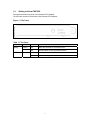
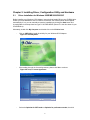
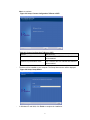
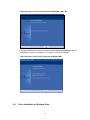
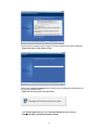
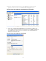
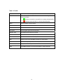
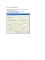
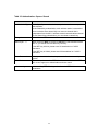
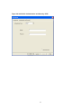
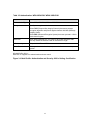
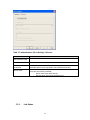
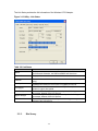
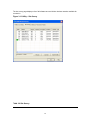
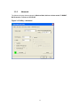
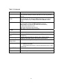
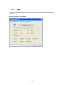
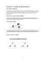
CWP-854
Wireless-G
PCI Adapter
User’s Manual
Table of Contents
Chapter 1.
Introduction............................................................................................... 6
1.1.
1.2.
1.3.
About CWP-854......................................................................................................6
Main Features.........................................................................................................6
Getting to Know CWP-854 .....................................................................................7
Chapter 2.
Installing Driver, Configuration Utility and Hardware ........................ 8
2.1.
2.2.
2.3.
Driver Installation for Windows 98SE/ME/2000/2003/XP.......................................8
Driver Installation for Windows Vista ................................................................... 10
Insert the Wireless-G PCI Adapter ...................................................................... 13
Chapter 3.
Using the Configuration Utility for 98SE/ME/2000/2003/XP/Vista ........ 15
3.1.
3.2.
3.3.
3.3.1.
3.3.2.
3.3.3.
3.3.4.
3.3.5.
3.3.6.
Overview.............................................................................................................. 15
Access the Configuration Utility........................................................................... 15
Getting to Know the Utility ................................................................................... 17
Profile.................................................................................................................. 17
Link Status ......................................................................................................... 28
Site Survey ......................................................................................................... 29
Statistics ............................................................................................................. 32
Advanced............................................................................................................ 33
About .................................................................................................................. 35
Appendix 1.
Appendix 2.
Troubleshooting ........................................................................................ 36
Planning Your Wireless Network.............................................................. 37
2
3
List of Figures
Figure 1-1 The Panel.......................................................................................................................7
Figure 2-1 AutoPlay Menu..............................................................................................................8
Figure 2-2 Setup: License Agreement ..........................................................................................8
Figure 2-3 Setup: Choose Configuration TxBurst or WiFi .........................................................9
Figure 2-4 Setup: Setup Status .....................................................................................................9
Figure 2-5 Setup: Click Finish to Complete (for WIN2000 / 2003 / XP)................................... 10
Figure 2-6 Setup: Click Finish to Complete (for WIN98 / ME) ................................................. 10
Figure 2-7 AutoPlay Confirm Window (Vista) ............................................................................11
Figure 2-8 AutoPlay Menu (Vista)................................................................................................11
Figure 2-9 Setup: License Agreement (Vista) ............................................................................11
Figure 2-10 Setup: Setup Status (Vista) .................................................................................... 12
Figure 2-11 Setup: plug-in message (Vista) .............................................................................. 12
Figure 2-12 Setup: Found New Hardware (Vista) ..................................................................... 12
Figure 2-13 Setup: Click Finish to Complete (Vista) ................................................................ 13
Figure 3-1 Utility Icon .................................................................................................................. 15
Figure 3-2 Wireless Zero Configuration: Select Manage......................................................... 15
Figure 3-3 Wireless Zero Configuration: Select Wireless Zero Configuration...................... 16
Figure 3-4 Wireless Zero Configuration: Select Disable ......................................................... 16
Figure 3-5 Utility – Profile ........................................................................................................... 17
Figure 3-6 Add Profile: Configuration ....................................................................................... 19
Figure 3-7 Add Profile: Authentication and Security: Open or Shared Key .......................... 21
Figure 3-8 Add Profile: Authentication and Security: LEAP ................................................... 23
Figure 3-9 Add Profile: Authentication and Security: WPA/ WPA-PSK/ WPA2/ WPA-PSK ... 24
Figure 3-10 Add Profile: Authentication and Security: 802.1x Setting: Certification ........... 25
Figure 3-11 Add Profile: Authentication and Security: 802.1x Setting: CA Server ............... 27
Figure 3-12 Utility - Link Status .................................................................................................. 29
Figure 3-13 Utility – Site Survey................................................................................................. 30
Figure 3-14 Utility – Statistics..................................................................................................... 32
Figure 3-15 Utility – Advanced ................................................................................................... 33
Figure 3-16 Utility - Link About................................................................................................... 35
Figure 17 Ad-hoc Mode ............................................................................................................... 37
Figure 18 Infrastructure Mode.................................................................................................... 37
4
List of Figures
Table 1-1 The Panel ........................................................................................................................7
Table 2-1 Choose Configuration TxBurst or WiFi........................................................................9
Table 3-1 Profile ........................................................................................................................... 18
Table 3-2 Configuration............................................................................................................... 20
Table 3-3 Authentication: Open or Shared................................................................................ 22
Table 3-4 Authentication: LEAP ................................................................................................. 24
Table 3-5 Authentication: WPA/ WPA-PSK/ WPA2/ WPA-PSK ................................................. 25
Table 3-6 Authentication: 802.1x Setting: Ceritication............................................................. 26
Table 3-7 Authentication: 802.1x Setting: CA Server ............................................................... 28
Table 3-8 Link Status ................................................................................................................... 29
Table 3-9 Site Survey................................................................................................................... 30
Table 3-10 Statistics..................................................................................................................... 32
Table 3-11 Advanced.................................................................................................................... 34
5
Chapter 1. Introduction
1.1.
About CWP-854
The Wireless-G PCI Adapter can be installed in most desktops and provides true flexibility by
allowing the computer to be positioned almost anywhere in the building without the cost and
hassle of running network cables. Using the wireless PCI adapter, you don't have to worry about
drilling holes in your walls and climbing through the attic or cellar to get connected to the network.
Once installed and connected, you can keep in touch with friends and work through e-mail,
instant messaging and chat rooms as well as sharing files and other network resources such as
printers and network storage with other computers.
The Wireless-G PCI Adapter connects to 802.11g networks at an incredible speed of 54Mbps and
for added versatility; it also interoperates with all Wireless-B (802.11b) products found at homes,
businesses, and public wireless hotspots around the country.
1.2.
Main Features
The following lists the main features of the Wireless-G PCI Adapter.
• 5 Times Faster and seamless operation with existing Wireless-B networks.
• Improves the coverage up to 300% greater than standard 802.11g.
• 64/128-bit WEP and WPA/WPA2 (Wi-Fi Protected Access) Encryption Provides Maximum
Wireless Security.
• Ease of Installation and Use.
• Compatible with Windows 98SE/ME/2000/2003/XP/Vista.
6
1.3.
Getting to Know CWP-854
This section describes the panel of the Wireless-G PCI Adapter.
The LEDs are located on the bracket of the Wireless-G PCI Adapter.
Figure 1-1 The Panel
Table 1-1 The Panel
LABEL
COLOR
S TAT U S
DESCRIPTION
Ready
Green
On
When the card links to a wireless device.
Off
The card does not link any wireless device.
Blinking
When the card transmits/receives data.
Off
No data is being transmitted or received
ACT
Green
7
Chapter 2. Installing Driver, Configuration Utility and Hardware
2.1.
Driver Installation for Windows 98SE/ME/2000/2003/XP
Before installing your Wireless-G PCI Adapter, insert the Auto-Install CD into your CD-ROM drive.
Unless you have disabled the auto-run feature of Windows, the AutoPlay Menu should appear
automatically. If not, you can manually access the installation by clicking the Start button and
choosing Run. In the drop-down box type D:\ AUTORUN.EXE (where D: is the drive letter for your
CD-ROM drive).
Alternately, double-click My Computer and double-click on the CD drive icon.
-
Click on CWP-854 to install driver/utility for your Wireless-G PCI Adapter.
Figure 2-1 AutoPlay Menu
-
After reading through the License Agreement, please click Yes to continue.
Figure 2-2 Setup: License Agreement
-
Select the Optimize for WiFi mode or Optimize for performance mode, then click
8
Next > to continue.
Figure 2-3 Setup: Choose Configuration TxBurst or WiFi
Table 2-1 Choose Configuration TxBurst or WiFi
OPTION
DESCRIPTION
Optimize for WiFi mode
The Tx BURST and TCP Window Size features
will be disabled.
Optimize for performance mode
The Tx BURST and TCP Window Size features
will be enabled.
-
The driver will be installed to your computer. The Setup Status screen will be displayed.
Figure 2-4 Setup: Setup Status
-
In Windows XP and 2000, click Finish to complete the installation.
9
Figure 2-5 Setup: Click Finish to Complete (for WIN2000 / 2003 / XP)
-
In Windows 98SE and ME, please select Yes, I want to restart my computer now and
click Finish to complete the installation. The system will restart automatically.
Figure 2-6 Setup: Click Finish to Complete (for WIN98 / ME)
2.2.
Driver Installation for Windows Vista
10
Before installing your Wireless-G Cardbus Adapter, insert the Auto-Install CD into your CD-ROM
drive.
-
There will be a Vista AutoPlay Confirm Window. Click Run AUTORUN.EXE icon.
Figure 2-7 AutoPlay Confirm Window (Vista)
-
Click on CWP-854 to install driver/utility for your Wireless-G USB Dongle.
Figure 2-8 AutoPlay Menu (Vista)
-
After reading through the License Agreement, please click Yes to continue.
Figure 2-9 Setup: License Agreement (Vista)
11
-
The driver will be installed to your computer. The Setup Status screen will be displayed.
Figure 2-10 Setup: Setup Status (Vista)
-
There will be a plug-in message screen. Please insert the Wireless-G USB Dongle into
the USB port at this moment.
Figure 2-11 Setup: plug-in message (Vista)
-
Click Ask me again later when the Found New Hardware window appears.
Figure 2-12 Setup: Found New Hardware (Vista)
12
-
Click Finish to complete the installation.
Figure 2-13 Setup: Click Finish to Complete (Vista)
2.3. Insert the Wireless-G PCI Adapter
To insert the Wireless-G PCI Adapter into a desktop computer, please follow the steps below:
Turn off your computer.
Open the case and locate an available PCI slot on the motherboard. Check with
computer manufacturer for instructions.
Slide the PCI Adapter into the PCI slot. Make sure that all its pins are touching the
slot's contacts. You may have to apply a bit of pressure to slide the adapter all the way
in. After the adapter is firmly in place, secure its fastening tab to your PC's chassis with
13
a mounting screw and close the case.
Attach the external antenna to the adapter’s antenna connector.
Power on your desktop PC.
Microsoft Windows will automatically detect and complete the Wireless-G PCI Adapter
installation.
Note: In Windows ME and 98SE, following the hardware installation Windows will ask to restart
the computer, just click Yes to restart.
14
Chapter 3. Using the Configuration Utility for
98SE/ME/2000/2003/XP/Vista
3.1.
Overview
The wireless Configuration Utility can be used to check link information, search for available
wireless networks, or to create profiles that hold different configuration settings.
3.2.
Access the Configuration Utility
The Configuration Utility icon will appear in your system tray. Double-click the icon.
Figure 3-1 Utility Icon
The utility contains six parts: Profile, Link Status, Site Survey, Statistics, Advance, and About.
You should change all your configuration settings for the Wireless-G PCI Adapter by using this
utility.
Note: In Windows XP, you should disable the Wireless Zero Configuration service following the
steps below:
A. Right Click My Computer on the desktop and select Manage.
Figure 3-2 Wireless Zero Configuration: Select Manage
15
The Computer Management window comes up. Select Services from the Services and
Applications menu. Scroll down to locate Wireless Zero Configuration service.
Figure 3-3 Wireless Zero Configuration: Select Wireless Zero Configuration
B. Double Click on Wireless Zero Configuration to go into its properties. For Startup type,
choose Disable to disable the Wireless Zero Configuration then click Apply and OK to make
the changes effective. Now you can use our Configuration Utility instead of Windows XP
Wireless Zero Configuration Utility.
Figure 3-4 Wireless Zero Configuration: Select Disable
16
3.3.
Getting to Know the Utility
3.3.1.
Profile
The Profile can keep your favorite wireless settings among your home, office and other public
hotspots. You may save multiple profiles and activate the correct one at your preference.
Figure 3-5 Utility – Profile
17
Table 3-1 Profile
LABEL
DESCRIPTION
Profile Name
Connection profile name. There is a connection icon standing for the
connection status,
: Indicate connection is successful on currently activated profile.
: Indicate connection fails on currently activated profile.
SSID
Wireless station or ad-hoc name.
Channel
Channel in use for this wireless connection.
Authentication
The Authentication method used for this profile.
Encryption
The Encryption type used for this profile.
Network Type
The Network type used for this profile.
Add
Click Add to create a new profile.
Delete
Click Delete to delete a selected profile.
Edit
Select a profile, and click Edit to change an existing profile.
Activate
To activate a specific profile, select the profile, and click Activate button.
OK
To pop-down this utility menu.
Help
Click Help to display on-line help information in a pop-up screen.
18
3.3.1.1. Create a New Profile
Click the Add button on the Profile screen to create a new profile.
(A) Add Profile: Configuration
Fill the Profile Name and SSID for this new profile.
Figure 3-6 Add Profile: Configuration
19
Table 3-2 Configuration
LABEL
DESCRIPTION
Profile Name
Enter the profile name that you want.
SSID
User can key in the intended SSID name or use pull down menu to
select from available wireless network.
PSM
CAM (Constantly Awake Mode) – the wireless NIC will stay full power
when AC power cord is plugged into power outlet.
PSM (Power Saving Mode) – the wireless NIC will enter the power
saving mode.
Network Type
There are two wireless modes.
(A) Infrastructure - This mode allows wireless and wired networks to
communicate through an access point.
(B) Ad-hoc - This mode allows wireless-equipped computers to
communicate directly with each other.
Preamble
There are three types: Auto, Long and Short are supported.
Ad-hoc wireless
mode
There are three types: 802.11B only, 802.11B/G mixed and 802.11G only
modes are supported.
TX Power
Transmit power, the amount of power used by a radio transceiver to
send the signal out. User can choose power value by sliding the bar.
RTS Threshold
User can adjust the RTS threshold number by sliding the bar or key in
the value directly. The default value is 2347.
Fragment Threshold
User can adjust the Fragment Threshold number by sliding the bar or
key in the value directly. The default value is 2346.
Channel
Only available for setting under ad-hoc mode. User can choose the
channel frequency to start their ad-hoc network.
OK
Confirms and saves the settings.
Cancel
Ignore the settings and return to the previous screen.
Help
Click Help to display on-line help information in a pop-up screen.
20
(B) Add Profile: Authentication and Security
Enter the authentication and security information here.
Figure 3-7 Add Profile: Authentication and Security: Open or Shared Key
21
Table 3-3 Authentication: Open or Shared
LABEL
DESCRIPTION
Authentication Type
Under Open System authentication, any wireless station can request
authentication.
Under Shared Key authentication, each wireless station is assumed to
have received a secret shared key over a secure channel that is
independent from the 802.11 wireless network communications channel.
To use Shared Key authentication, you must have a network key.
Encryption
Select None or WEP
WEP Key#1 .. 4
When select the WEP encryption or Shared Key authentication without
802.1x, you should enter the WEP key correctly.
If the WEP key is 64-bit, please enter 10 hexadecimal or 5 ASCII
characters.
If the WEP key is 128-bit, please enter 26 hexadecimal or 13 ASCII
characters.
Show Password
When you check this function, the password will not be covered by *
symbol.
Use 802.1x
Select this option to enable IEEE 802.1x for user authentication. IEEE
802.1x can support true authentication and user control
802.1x setting
When enabling IEEE 802.1x, you should set the IEEE 802.1x
parameters.
22
Figure 3-8 Add Profile: Authentication and Security: LEAP
23
Table 3-4 Authentication: LEAP
LABEL
DESCRIPTION
Authentication Type
Identity
Light Extensible Authentication Protocol. It is an EAP authentication type
used primarily in Cisco Aironet WLANs. It encrypts data transmissions
using dynamically generated WEP keys, and supports mutual
authentication.
Enter identity for the LEAP authentication service
Password
Enter password for the LEAP authentication service.
Show Password
When you check this function, the password will not be covered by *
symbol.
Figure 3-9 Add Profile: Authentication and Security: WPA/ WPA-PSK/ WPA2/
WPA-PSK
24
Table 3-5 Authentication: WPA/ WPA-PSK/ WPA2/ WPA-PSK
LABEL
DESCRIPTION
Authentication Type
Select WPA, WPA-PSK, WPA2 or WPA-PSK
Encryption
Specify an encryption method to use.
Select TKIP (Temporal Key Integrity Protocol) that uses a stronger
encryption algorithm and protects against hackers with MIC (Message
Integrity Check).
Select AES (Advanced Encryption System) that uses symmetric 128-bit
block data encryption.
WPA-PSK
Enter WPA Preshared Key, only valid for WPA-PSK and WPA2-PSK.
This key should be between 8 and 32 characters in length.
802.1x setting
Only valid for WPA and WPA2.
Show Password
When you check this function, the password will not be covered by *
symbol.
(C) Add Profile: 802.1x
IEEE 802.1x supports true authentication and user control.
Figure 3-10 Add Profile: Authentication and Security: 802.1x Setting: Certification
25
Table 3-6 Authentication: 802.1x Setting: Ceritication
LABEL
DESCRIPTION
Authentication Type
PEAP: Protected Extensible Authentication Protocol. PEAP transports
authentication data by using tunneling between PEAP clients and an
authentication server. PEAP can authenticate wireless LAN clients using
only server-side certificates, thus simplifying the implementation and
administration of a secure wireless LAN.
TLS/Smart Card: Transport Layer Security, provides with
certificate-based and mutual authentication of the client and the network.
It relies on client-side and server-side certificates to perform
authentication and can be used to dynamically generate user-based and
session-based WEP keys to secure subsequent communications
between the WLAN client and the access point.
TTLS: Tunneled Transport Layer Security, this security method provides
for certificate-based, mutual authentication of the client and network
through an encrypted channel. Unlike EAP-TLS, EAP-TTLS requires
only server-side certificates.
MD5-Challenge: Message Digest Challenge, is an EAP authentication
type that provides base-level EAP support. It only supports one-way
authentication i.e. there is no mutual authentication of wireless client and
the network. It’s only valid for profile’s authentication type to be none or
shared.
26
Table 3-6 Authentication: 802.1x Setting: Ceritication
LABEL
DESCRIPTION
Session Resumption
User can choose Disabled, Reauthenticate, Roaming, SameSsid or
Always.
Identity
Enter the Identity for server
Password
Enter the Password for server
Use Client Certificate
Enable the client certificate for server authentication.
Tunnel Authentication
Protocol
Tunnel protocol, List information includes EAP-MSCHAP,
EAP-MSCHAP v2, CAHAP and MD5.
Identity
Enter Identity for tunnel
Password
Enter Password for tunnel
If you want to use CA server, please click CA Server page. Depending on the EAP in use, only
the server or both the server and client may be authenticated and require a certificate. Server
certificates identify a server, usually an authentication or RADIUS server to clients. Most EAPs
require a certificate issued by a root authority or a trusted commercial CA.
Figure 3-11 Add Profile: Authentication and Security: 802.1x Setting: CA Server
27
Table 3-7 Authentication: 802.1x Setting: CA Server
LABEL
DESCRIPTION
Use certificate chain
Enable the certificate feature
Certificate issuer
Choose to use server that is the issuer of certificates.
Allow intermidiate
certificates
It must be in the server certificate chain between the server
certificate and the server specified in the certificate issuer field.
Server name
Enter the authentication server’s name.
There are two matching methods,
- Server name must match exactly.
- Domain name must end in specified name.
3.3.2.
Link Status
28
The Link Status provides the link information of the Wireless-G PCI Adapter.
Figure 3-12 Utility - Link Status
Table 3-8 Link Status
LABEL
DESCRIPTION
Status
Displays current connection status. If no connection, it will show
Disconnected. Otherwise, the SSID and BSSID will show here.
Displays link status and current channel in use.
Extra Info
Channel
Link Speed
Throughput
Link Quality
Signal Strength
Noise Level
3.3.3.
Shows the channel which the wireless network devices are currently
using.
Tx(Mbps) field shows the transfer rate in megabits per second.
Rx(Mbps) field shows the receive rate in megabits per second.
Shows the amount of data moved successfully form one place to
another in a given time period.
The level of Link Quality is displayed here by a bar indicating
percentage, between 0 and 100 percent.
The level of Signal Strength is displayed here by a bar indicating
percentage, between 0 and 100 percent.
The Noise Level is displayed here by a bar indicating percentage,
between 0 and 100 percent.
Site Survey
29
The site survey page displays a list of all Infrastructure and Ad-hoc wireless networks available for
connection.
Figure 3-13 Utility – Site Survey
Table 3-9 Site Survey
30
LABEL
DESCRIPTION
SSID
Service Set ID of the Wireless Network.
BSSID
Basic Service Set ID of the Wireless Network.
Signal
Signal Strength status.
Channel
The channel used by Wireless Network.
Encryption
Encryption type.
Authentication
Authentication type used.
Network Type
Wireless Network mode. (Infrastructure mode or Ad-hoc mode)
Rescan
Click Rescan to re-search for wireless networks.
Connect
Select one of the networks on the list, and click the Connect button.
Please note that if the wireless network has encryption enabled, you
can’t connect. If you want to connect, you must add a profile in the
Profile Tab.
Note: There is no Connect button in Window Vista. You have to use the
Add Profile feature to build the wireless connection with the selected
network. Please refer to the Profile information.
Add the selected network to Profile List.
Add Profile
31
3.3.4.
Statistics
The Statistics screen provides information about the Transmit and Receive Statistics. You can
reset counters if you need, otherwise click OK.
Figure 3-14 Utility – Statistics
Table 3-10 Statistics
LABEL
DESCRIPTION
Transmit Statistics
Displays current transmit frame information
Receive Statistics
Displays current receive frame information.
Reset Counter
Resets all counter to zero.
32
3.3.5.
Advanced
The Advanced screen shows settings for Wireless Mode, Ad-hoc wireless mode, TX BURST,
B/G Protection, Tx Rate and RF On/Off.
Figure 3-15 Utility – Advanced
33
Table 3-11 Advanced
LABEL
DESCRIPTION
Wireless mode
Tx Rate
802.11 B only: allows to connect to the 802.11b wireless stations only.
802.11 B/G mix: allows to connect to the 802.11b or 802.11g wireless
stations.
When the network type is in Ad Hoc mode that the card can only work in
802.11b data rate. It is defined by Wi-Fi organization. If you want to
enable the data rate up to 54Mbps, please select Ad-hoc wireless
mode.
If there are 802.11b and 802.11g wireless stations in the network, it is
recommended to enable the B/G Protection mechanism.
Auto: Based on the status of the network and automatically
disable/enable protection mode.
On: Always send frame with protection.
Off: Always send frame without protection.
Manually selected the transmit rate. Default is auto.
Tx Burst
A proprietary frame burst mode which can improve transmission speed.
Enable TCP Window
Size
Enables the TCP Window Size to improve the TCP performance over
wireless link.
Fast Roaming
Roaming mechanism setup by transmit power. Roaming will be
happened if the station power is less than the defined power.
Selects the correct region code for your country.
Ad-hoc wireless
mode
B/G Protection
Select Your Country
Region Code
CCX2.0
Turn off RF/ Turn on
RF
Apply
Supports Cisco Compatible Extensions functions:
1.
LEAP turn on CCKM
2.
Enable Radio Measurement: Channel measurement every 0~2000
milliseconds.
You can turn off or turn on the RF feature.
Save the changes.
34
3.3.6.
About
The About screen shows release dates as well as driver/utility versions and the MAC/IP address
of the card.
Figure 3-16 Utility - Link About
35
Appendix 1. Troubleshooting
PROBLEM
C O R R E C T I V E AC T I O N
None of the LEDs turn on when I
insert the WLAN card.
Make sure you have turned on your computer
Make sure you have installed the correct utility and driver for your WLAN
card.
Restart your computer and insert the WLAN card.
Make sure there is no hardware conflict. Check your computer resource
information.
I cannot access the configuration
utility
Make sure the WLAN card is inserted properly.
I cannot connect to a wireless
network
Make sure the ACT LED on the WLAN card is blinking.
Make sure you have installed the correct utility version.
Make sure the wireless router is within range. Move your computer
closer to the wireless router.
Make sure that you have set the wireless network settings correctly. For
example, the SSID and security settings.
Make sure there is no radio interference (for example, cordless phones,
microwave oven, etc) that may affect wireless transmission quality.
36
Appendix 2. Planning Your Wireless Network
A2-1 Network Topology
A wireless local area network (WLAN) is exactly like a regular local area network (LAN), except
that each computer in the WLAN uses a wireless device to connect to the network. Computers in
a WLAN share the same frequency channel and SSID, which is an identification name for
wireless devices.
A2-2 Ad-hoc versus Infrastructure Mode
An ad-hoc wireless LAN is a group of computers, each equipped with one WLAN adapter,
connected as an independent wireless LAN. Computers in a specific ad-hoc wireless LAN must
all be configured to share the same radio channel.
Figure 17 Ad-hoc Mode
An integrated wireless and wired LAN is called an Infrastructure configuration. In this mode, a
group of wireless nodes and an Access Point compose a Basic Service Set (BSS). Each wireless
node in a BSS can talk to any computer in the wired LAN infrastructure via the Access Point.
Figure 18 Infrastructure Mode
37