1
T
ECHNICAL INFORMATION
Model No.
Description
PRODUCT
P 1/ 12
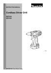
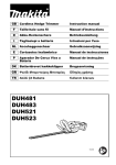
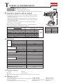
BDF458 (LXFD03*1)
18V Cordless Driver Drill
L
*1 Model number for North and Central American countries
CONCEPT AND MAIN APPLICATIONS
Model BDF458 (LXFD03*1) is a successor model of BDF454, featuring:
• Extremely compact tool size with an overall length of 225mm (8-7/8") the shortest in its class
• High power and productivity achieved with new DC motor (FD31-30)
• Enhanced dust and drip-proof performance to ensure reliable operation
even under bad weather.
• Equipped with Battery fuel gauge*2 for increased maneuverability.
H
*2 Not available for model LXFD03.
Note: This product is not compatible with 18V-1.3Ah battery BL1815.
This product is available in the following variations.
Plastic
Battery
Battery Charger carrying
Model No.
Type Quantity cover
case
BDF458Z
No
No
No
No
No
BDF458RFE BL1830
1
DC18RC
2
Yes
3
2
BDF458RFE3 BL1830
DC18RC
Yes
BDF458ZX
No
No
No
No
No
BDF458RFX BL1830
2
1
DC18RC
No
LXFD03Z*1
No
No
No
No
No
BL1830
2
1
DC18RA
Yes
LXFD03*1
Specification
Voltage: V
Capacity: Ah
Battery Energy capacity: Wh
Cell
Charging time (approx.): min.
High
No load speed:
minˉ¹=rpm Low
Capacity of drill chuck: mm (")
Steel
Capacity: mm (")
Wood
Torque setting
Clutch torque setting: N.m (in.lbs)
Max lock torque: N.m (in.lbs)
Soft joint
Max fastening
torque: N.m (in.lbs) Hard joint
Electric brake
Mechanical speed control
Variable speed control
Reversing switch
LED job light
Weight according to
EPTA-Procedure 01/2003*4: kg (lbs)
*3 for North and Central American countries
Standard equipment
Systainer Housing
case
color
No
No
No
Makita
Yes
blue
Yes
No
No
W
Dimensions: mm (")
Length (L) 225 (8-7/8)
79 (3-1/8)
Width (W)
Height (H) 259 (10-1/4)
18
3.0
54
Li-ion
22 with DC18RC (DC18RA*3)
0 - 2,000
0 - 400
1.5 (1/16) - 13 (1/2)
13 (1/2)
76 (3)
21 stage + drill mode
1.0 - 10.0 (9 - 89)
84 (750)
58 (520)
91 (810)
Yes
Yes (2 speeds)
Yes
Yes
Yes
2.3 (5.0)
*4 with Battery BL1830
+ – bit 2-45 ................ 2
Belt clip ..................... 1
Bit holder .................. 1
Grip assembly ............ 1
Note: The standard equipment for the tool shown above may vary by country.
Optional accessories
Fast charger DC18RA
(for US, Canada, Guam, Panama, Mexico and Colombia)
Fast charger DC18RC
(for all countries except the countries above)
Charger DC18SD
Charger DC24SC
Automotive charger DC18SE
Battery BL1830
Battery protectors
Drill bits for wood
Drill bits for steel
Driver bits
P 2/ 12
Repair
CAUTION: Repair the machine in accordance with “Instruction manual” or “Safety instructions”.
[1] NECESSARY REPAIRING TOOLS
Code No.
1R359
Description
Use for
(Use this tool if Drill chuck cannot be removed by the method of
Drill chuck removing tool
described in “[3]-1 Drill chuck disassembling”.)
Hex wrench 10
removing/ mounting Drill chuck
[2] LUBRICATION
It is not required to lubricate the gear section because the portion is replaced as a factory-assembled gear unit.
[3] DISASSEMBLY/ASSEMBLY
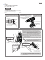
[3] -1. Drill Chuck
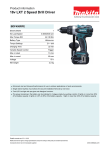
DISASSEMBLING
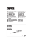
(1) Remove M6x22 Flat head screw as drawn in Fig. 1.
(2) Preset the machine as drawn in Fig. 2. And set Hex wrench 10 to Vise as drawn in Fig. 3.
(3) Gripping Hex wrench 10 with Drill chuck firmly, remove Drill chuck as drawn in Fig. 4.
Fig. 1
Fig. 2
Open Drill chuck fully and remove M6x22
Flat head screw by turning it clockwise.
Set Change ring
to Drill mode.
Change ring
Speed change lever
Set Speed change lever
to Low speed mode
designated with 1.
Note: Use Impact driver to unscrew
M6x22 Flat head screw if it
could not be removed
manually.
F/R change lever
Set F/R Change lever
to Reverse (counterclockwise) rotation.
M6x22 Flat head screw (Left handed thread)
Attach Battery.
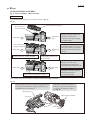
Fig. 3
CORRECT
Hold the long end.
Hex wrench 10
Setting of
Hex wrench
10
WRONG
Grip flat surfaces
of Hex wrench 10.
Vise
[A]
Vise
Do not hold edges
of Hex wrench 10.
Do not hold
the short end.
[A]
Hex wrench 10,
viewed from side [A]
Hex wrench 10,
viewed from side [A]
Fig. 4
Counterclockwise
Counterclockwise* force to be applied by operator
Clockwise
Clockwise* recoil force
of Machine
Hex wrench 10
Vise
*Note: The rotational direction is viewed from operator.
1. Hold Hex wrench 10 with Drill chuck and grip Machine.
Important:
Grip Machine tightly with both hands to provide
the sufficient counterclockwise* force against clockwise*
recoil force of Machine.
2. Pull Switch trigger slowly.
3. Spindle rotates counterclockwise* and consequently
Drill chuck is removed from spindle.
P 3/ 12
Repair
[3] DISASSEMBLY/ASSEMBLY
[3] -1. Drill Chuck (cont.)
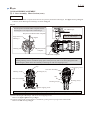
ASSEMBLING
(1) Set the machine. (Fig. 5 and 6)
(2) Set Hex wrench 10 to vise and described in Fig. 3.
(3) Set Drill chuck in place. (Fig. 7)
Fig. 6
Fig. 5
Turn Drill chuck clockwise by hand until
it sits on the end of the threaded portion
of Spindle.
Drill chuck
Set Speed change lever to Low speed
mode designated with 1.
Speed change lever
Set F/R Change lever
to Forward (clockwise)
rotation.
Set Change ring to Drill mode.
Change ring
F/R change lever
Attach Battery.
End of the threaded
portion of Spindle
Fig. 7
Clockwise* force to be
applied by operator
*Note: The rotational direction is viewed from operator.
1. Hold Hex wrench 10 with Drill chuck and grip Machine.
Important: Grip Machine hard with both hands to provide
sufficient clockwise* force against
counterclockwise* recoil force of Machine.
2. Pull Switch trigger slowly to turn Spindle clockwise*.
Note: Pull the Trigger so that Spindle’s rotating reaches full
speed in one second.
3. Drill chuck is tightened and consequently Spindle is locked.
4. Open Drill chuck fully, and tighten Drill chuck
with M6x22 Flat head screw by turning it
counterclockwise with Impact driver.
Clockwise
Counterclockwise
Counterclockwise recoil
force of Machine
Hex wrench 10
M6x22 Flat head screw
(Left handed thread)
Note: Apply adhesive (ThreeBond 1321B/1342 or Loctite 242)
to threaded portion when re-using the removed M6x22
Flat head screw.
P 4/ 12
Repair
[3] DISASSEMBLY/ASSEMBLY
[3] -2. Gear Assembly, Motor Section
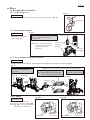
DISASSEMBLING
After removing Drill chuck (Re: Figs. 1, 2, 3 and 4), disassemble Motor section and Gear assembly. (Figs. 8 and 9)
Fig. 8
1. Remove two 3x16 Tapping screws and Rear cover.
And remove four 4x18 Tapping screws.
2. Remove Housing R, unscrewing
seven 3x16 Tapping screws.
3x16 Tapping screw (7 pcs.)
Rear cover
3x16 Tapping
screw (2 pcs.) 4x18 Tapping
screw (4 pcs.)
3. Pull out Heat sink section, and remove Gear assembly
together with Motor section and Speed change lever.
Motor section
Speed change lever
4. Remove Speed change lever and Motor section
from Gear assembly.
Motor section
Gear assembly
Speed change
lever assembly
Heat sink
section
5. Push Speed change lever assembly toward Motor side 6. Lifting up Motor side of Speed change lever assembly,
pull it toward the direction designated with arrow.
until it stops to have space between the pin on the lever
of Gear assembly and rear Compression spring 4.
Motor side
Drill chuck side
rear
Compression
spring 4
Motor side
Drill chuck side
Pin on
the lever of
Gear assembly
Space between rear Compression spring 4
and the pin on the lever of Gear assembly.
front Compression spring 4 compressed
by the lever of Gear assembly
Fig. 9
5. Shift the tail of Torsion spring from top of Carbon
brush to the Notch of Brush holder. Carbon brush
gets free from the pressure of Torsion spring.
Carbon brush
Torsion spring
6. From Armature, pull off Brush holder complete and Yoke unit.
Yoke unit
Armature
Brush holder complete
Note: Pay attention not to pinch your finger between Yoke unit and Armature when removing.
Do not scratch the copper wires of Armature. Yoke unit draws Armature by its considerable
strong magnet force.
P 5/ 12
Repair
[3] DISASSEMBLY/ASSEMBLY
[3] -2. Gear Assembly, Motor Section (cont.)
ASSEMBLING
(1) Assemble Motor section taking the reverse step of Disassembling. Refer to Fig. 9.
Insert Armature into Yoke unit as drawn in Fig. 10.
Fig. 10
[Correct]
[Wrong]
Notch
Yoke unit has to be assembled to Armature so that its notch is located
on the drive-end side.
Note in Assembling:
1. Do not pinch your finger between Armature fan and Yoke unit.
2. Insert Armature into Yoke unit carefully so that its wire does not
damage.
(2) Assemble Brush holder complete to Commutator end of Armature. Refer to the drawings in Fig. 9.
Carbon brushes in Brush holder complete have to be still left from Armature’s commutator in this step.
(3) Fasten Heat sink with Pan head screw to Yoke unit. And insert the Motor section into Gear assembly, while engaging
Armature’s gear with the Planet gears in Gear assembly. Refer to the center right drawing in Fig. 8.
(4) Before mounting Speed change lever assembly, make sure that Lead springs and Compression springs are assembled
to Speed change lever assembly. See Fig. 11.
Fig. 11
Leaf spring ( 2 pcs.)
Compression
spring 4 ( 2 pcs.)
P 6/ 12
Repair
[3] DISASSEMBLY/ASSEMBLY
[3] -2. Gear Assembly, Motor Section
ASSEMBLING
(5) Assemble Speed change lever assembly as drawn in Fig. 12.
Fig. 12
Pin on the lever
of Gear assembly
front Compression spring 4
1. Apply the front Compression
spring 4 of Speed change lever
Drill chuck
assembly to the flat side
side
(without pin) of Gear assembly
for Speed change.
Motor side
2. Push Speed change lever assembly
toward Motor side until it stops to
have space between pin of Gear
Drill chuck
assembly and rear Compression
side
spring 4.
rear Compression
spring 4
Motor side
Space between rear Compression spring 4
and pin on the lever of Gear assembly
front Compression spring 4
compressed by the lever of
Gear assembly.
Drill chuck
side
Motor side
Pin on the lever of Gear assembly fit to
the coil of rear Compression spring 4
3. Fit the pin of Gear assembly to
Spring’s coil with slowly
returning Speed change lever
assembly toward Drill chuck side.
4. Slide Speed change lever
assembly to the either position
2(High speed mode) or
1 (Low speed mode).
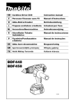
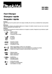
(6) Assemble Motor section and Gear assembly as illustrated in Figs. 13 and 14.
Fig. 13
While aligning the notch of Yoke unit with projection of
Housing L, mount Yoke unit together with Gear ass’y
and Motor section to Housing L.
If the Motor section does not fit to
Housing L, make sure that Yoke unit
is correctly amounted to Armature.
See Fig. 10.
Housing Set (L)
Brush holder complete
protrusion
Gear ass’y
notch
Yoke unit
P 7/ 12
Repair
[3] DISASSEMBLY/ASSEMBLY
[3] -2. Gear Assembly, Motor Section (cont.)
ASSEMBLING
(7) Make sure Brush holder complete and Yoke unit are precisely mounted to Housing R. See upper drawing in Fig. 14.
And then, mount Housing R to Housing L as drawn in Fig. 14.
Fig. 14
The flat portion of Brush holder complete must be
at 90 degrees to the edge surface of Housing L.
rib of Housing L
Yoke unit
Attach the edge of Yoke unit
to the rib of Housing L.
flat portion of Brush holder complete
edge surface of
Housing L
Housing L
90 degrees
Brush holder
complete
Brush holder complete
Gap arises between Housing R and L when Gear assembly is fastened to Housing R and L.
Holding Housing R and L with Water pump pliers at the portion by their screw holes (designated with
black triangles), fasten Gear case assembly to Housing set with 4x18 Tapping screws.
Gap
Gear case assembly
Housing set (R)
4x18 Tapping screw
Housing set (L)
Gap
Gear case assembly
Housing set (R)
Housing set (L)
4x18 Tapping screw
Note in Assembling: Be careful not to give any damage on Housing set when holding with Water pump pliers.
(8) Fasten Housing R to Housing L with seven 3x16 Tapping screws.
Refer to the upper right drawing in Fig. 8.
(9) Contact Carbon brush with Armature’s commutator, putting Torsion spring on the Carbon brush.
Refer to the left drawing in Fig. 9.
P 8/ 12
Repair
[3] DISASSEMBLY/ASSEMBLY
[3] -3. F/R Change Lever
Fig. 15
ASSEMBLING
Prong
Put the projection on Switch between the prongs of F/R change lever. (Fig. 15)
Projection
[3] -4. Switch plate complete
Fig. 16
ASSEMBLING
Set Switch plate complete
in place. (Fig. 16)
Insert Switch plate complete to Housing L,
facing its symbol of Fuel gauge to
Housing R side.
Note: Switch plate complete with
faced in the wrong direction
can not be inserted to
Housing L.
Housing R side
Switch plate
complete
Housing L
Symbol of
Fuel gauge
[3] -5. Parts related to Drip-proof structure
ASSEMBLING
Assemble Sponge B to Housing L. And assemble Seal and Sponge A to Housing L as drawn in Fig. 17.
Fig. 17
Assemble Sponge B to Housing R
to the portion designated with
gray color.
Sponge B
Housing R
Note: To assure Drop-proof, use new Sponge A and Sponge B.
Assemble Sponge A to Seal.
Note: Edge of the assembled Sponge A
has to be flat to the surface of Seal.
Assemble the Seal to
Housing L as drawn below.
Housing L
Sponge A
Seal
[3]-6. Cushion
ASSEMBLING
Be sure to install Cushion into
Housing set (L) as drawn in Fig. 18R.
Note: Fig. 18F is the wrong installation.
Pay attention to the direction.
Fig. 18R
Fig. 18F
[Correct]
Housing set (L)
[Wrong]
Cushion
Housing set (L)
Cushion
P 9/ 12
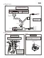
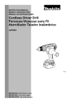
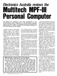
Circuit diagram
Fig. D-1
Circuit with Battery fuel gauge
available for the countries
other than North American countries
Black
Red
Color index of lead wires' sheath
Yellow
Blue
LED
Brush holder
complete
FET
Red Lead wire is used
for some countries
instead of white.
Switch
Light
circuit
Terminal
Wiring diagram
Fig. D-3
Fig. D-2
Wiring of LED Lead Wires
(before setting Switch)
Wiring to Terminal
Fix LED lead wires with Lead wire holders
drawn below.
The Flag connector has to be connected so that
its wire connecting portion is located over
the mark of + - poles.
Wire connecting
portion
LED
Lead wire
holder
Their lead wires must
be tight between Lead
wire holders so that
Switch can be set in
place.
P 10/ 12
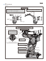
Wiring diagram
Fig. D-4
Wiring to Switch
Connect the Lead wires to Switch, tilting their
Connectors to 45 degrees as drawn below.
Fix the FET Lead wires as follows:
yellow with Lead wire holder nearest to Switch trigger
blue with the center Lead wire holder
black with Lead wire holder farthest from Switch trigger
45 degrees
FET
black blue
Lead wire
holder
yellow
FET
Switch trigger
Fig. D-5
with Battery fuel gauge available for the countries
other than North American countries
Wiring in Housing L
Brush holder complete
Put Pigtail of Carbon brush
in the area marked with gray
color to avoid pinching with
Rear cover.
9 mm
9 mm
Put Line filter in
this place.
Line filter
Pig tail of Carbon brush
Put the bundled Lead wires
into the groove of Sponge.
Seal
Pay attention, not to put
Lead wires on the Seal.
Sponge
Connector
Lead wires connected to
Connector have to be fixed
with Lead wire holders.
Light circuit
P 11/ 12
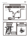
Circuit diagram
Fig. D-1A
Circuit without Battery fuel gauge
available exclusively for North American countries
Color index of lead wires' sheath
Yellow
White
Blue
Black
Red
LED
Brush holder
complete
FET
Switch
Terminal
Wiring diagram
Fig. D-2A
Fig. D-3A
Wiring of LED Lead Wires
(before setting Switch)
Wiring to Terminal
Fix the LED lead wires
with Lead wire holders
drawn below.
The Flag connector has to be connected so
that its wire connecting portion is located
over the mark of + - poles.
Wire connecting
portion
LED
Lead wire
holder
Their lead wires must be
tight between Lead wire
holders so that Switch
can be set in place.
P 12/ 12
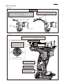
Wiring diagram
Fig. D-4A
Wiring to Switch
Fix FET Lead wires as follows:
yellow with Lead wire holder nearest to Switch trigger
blue with the center Lead wire holder
black with Lead wire holder farthest from Switch trigger
Connect Lead wires to Switch, tilting their
Connectors to 45 degrees as dran below.
45 degrees
FET
black blue
Lead wire
holder
yellow
FET
Switch trigger
Fig. D-5A
without Battery fuel gauge
available exclusively for North American countries
Wiring in Housing set (L)
Brush holder complete
Put Pigtail of Carbon brush
in the area marked with gray
color to avoid pinching with
Rear cover.
9 mm
9 mm
Pigtail of Carbon brush
Put the bundled Lead wires
into the groove of Sponge.
Seal
Pay attention not to put
Lead wires on the Seal.
Lead wires connected to
Connector have to be fixed
with Lead wire holders.