Download Cisco UCS-CPU-E5-4617= processor

Transcript
Cisco UCS B420 M3
Blade Server
CISCO SYSTEMS
170 WEST TASMAN DR.
SAN JOSE, CA, 95134
WWW.CISCO.COM
PUBLICATION HISTORY
REV A.19
OCTOBER 24, 2013
OVERVIEW . . . . . . . . . . . . . . . . . . . . . . . . . . . . . . . . . . . . . . . . . . . . . . . 3
DETAILED VIEWS . . . . . . . . . . . . . . . . . . . . . . . . . . . . . . . . . . . . . . . . . . . 4
Blade Server Front View . . . . . . . . . . . . . . . . . . . . . . . . . . . . . . . . . . . . . . . . . . . . . . .4
BASE SERVER STANDARD CAPABILITIES and FEATURES . . . . . . . . . . . . . . . . . 5
CONFIGURING the SERVER . . . . . . . . . . . . . . . . . . . . . . . . . . . . . . . . . . . . 7
STEP
STEP
STEP
STEP
STEP
STEP
STEP
STEP
STEP
STEP
STEP
STEP
STEP
1 VERIFY SERVER SKU . . . . . . . . . . . . . . . . . . . . . . . . . . . . . . . . . . . . . . . . . . . . 8
2 CHOOSE CPU(S) . . . . . . . . . . . . . . . . . . . . . . . . . . . . . . . . . . . . . . . . . . . . . . 9
3 CHOOSE MEMORY . . . . . . . . . . . . . . . . . . . . . . . . . . . . . . . . . . . . . . . . . . . . 10
4 CHOOSE DISK DRIVES (OPTIONAL) . . . . . . . . . . . . . . . . . . . . . . . . . . . . . . . . . . 13
5 CHOOSE ADAPTERS . . . . . . . . . . . . . . . . . . . . . . . . . . . . . . . . . . . . . . . . . . . 15
6 ORDER A TRUSTED PLATFORM MODULE (OPTIONAL) . . . . . . . . . . . . . . . . . . . . . . 19
7 ORDER CISCO FLEXIBLE FLASH SECURE DIGITAL CARDS . . . . . . . . . . . . . . . . . . . . 20
8 ORDER INTERNAL USB 2.0 DRIVE (OPTIONAL) . . . . . . . . . . . . . . . . . . . . . . . . . . 21
9 ORDER FLASH-BACKED WRITE CACHE (OPTIONAL) . . . . . . . . . . . . . . . . . . . . . . . 22
10 CHOOSE OPERATING SYSTEM AND VALUE-ADDED SOFTWARE . . . . . . . . . . . . . . . 23
11 CHOOSE OPERATING SYSTEM MEDIA KIT (OPTIONAL) . . . . . . . . . . . . . . . . . . . . 26
12 CHOOSE SERVICE and SUPPORT LEVEL . . . . . . . . . . . . . . . . . . . . . . . . . . . . . . 27
13 CHOOSE LOCAL KVM I/O CABLE* (OPTIONAL) . . . . . . . . . . . . . . . . . . . . . . . . . 32
SUPPLEMENTAL MATERIAL . . . . . . . . . . . . . . . . . . . . . . . . . . . . . . . . . . . 33
System Board . . . . . . . . . . . . . . . . . . . . . . . . . . . . . . . . .
DIMM and CPU Layout . . . . . . . . . . . . . . . . . . . . . . . . . . . .
DIMM Population Order . . . . . . . . . . . . . . . . . . . . . . . . . . .
Network Connectivity . . . . . . . . . . . . . . . . . . . . . . . . . . . .
VIC 1240 and Port Expander for VIC 1240 . . . . . . . . . . .
Connectivity Using the Cisco UCS 2208XP Fabric Extender
Connectivity using the Cisco UCS 2204XP Fabric Extender
Connectivity using the Cisco UCS 2104XP Fabric Extender
. . . . . . . . . . . . . . . . . . . . 33
. . . . . . . . . . . . . . . . . . . . 35
. . . . . . . . . . . . . . . . . . . . 36
. . . . . . . . . . . . . . . . . . . . 40
. . . . . . . . . . . . . . . . . . . . 42
. . . . . . . . . . . . . . . . . . . . 43
. . . . . . . . . . . . . . . . . . . . 52
. . . . . . . . . . . . . . . . . . . . 61
TECHNICAL SPECIFICATIONS . . . . . . . . . . . . . . . . . . . . . . . . . . . . . . . . . . 67
Dimensions and Weight . . . . . . . . . . . . . . . . . . . . . . . . . . . . . . . . . . . . . . . . . . . . . . . 67
Power Specifications . . . . . . . . . . . . . . . . . . . . . . . . . . . . . . . . . . . . . . . . . . . . . . . . 67
2
Cisco UCS B420 M3 Blade Server
OVERVIEW
OVERVIEW
Designed for enterprise performance and scalability, the Cisco® UCS B420 M3 Blade Server combines the
advantage of 4-socket computing with the cost-effective Intel® Xeon® processor E5-4600 product family,
for demanding virtualization and database workloads.
With industry-leading compute density, I/O bandwidth and memory footprint, the UCS B420 M3 is a
balanced, high-performance platform that complements the UCS blade server portfolio. The full-width UCS
B420 M3 supports 1.5 TB of memory and leverages UCS VIC technology for up to 160 Gb aggregate I/O
bandwidth.
The UCS B420 M3 is part of the Cisco Unified Computing System (UCS) that combines blade and rack servers
with networking and storage access into a single unified system. Centrally configured through unified,
model-based management, Cisco UCS simplifies and speeds deployment of enterprise-class applications
running in bare-metal, virtualized and cloud-computing environments.
Figure 1
Cisco UCS B420 M3 Blade Server
3
DETAILED VIEWS
DETAILED VIEWS
Blade Server Front View
Figure 2 is a detailed front view of the Cisco UCS B420 M3 Blade Server.
Blade Server Front View
1
Drive bay 1
8
Power button and LED
2
Drive bay 2
9
Network link status LED
3
Drive bay 3
10
Blade health LED
4
Drive bay 4
11
Console connector1
5
Blade ejector handle
12
Reset button access
6
Asset pull handle
13
Beaconing LED and button
-
-
Figure 2
(a blank asset tag is provided on which
you can add your own label or sticker or
you can use a marker to write your asset
information on the tag)
7
Blade ejector handle
Notes
1. For information about the KVM local I/O cable that plugs into the console connector (a cable is included with
every Cisco UCS 5100 Series blade server chassis accessory kit), see CHOOSE LOCAL KVM I/O CABLE*
(OPTIONAL) on page 32.
4
Cisco UCS B420 M3 Blade Server
BASE SERVER STANDARD CAPABILITIES and FEATURES
Table 1 lists the capabilities and features of the base server. Details about how to configure the server for
a particular feature or capability (for example, number of processors, disk drives, or amount of memory)
are provided in CONFIGURING the SERVER on page 7.
NOTE: The B420 M3 blade server requires UCS Manager 2.0 (4b) or later to operate
as part of the UCS system.
Table 1 Capabilities and Features
Capability/Feature
Description
Blade server chassis
The full-width UCS B420 M3 Blade Server mounts in a Cisco UCS 5100 series
blade server chassis
CPU
Up to four Intel® E5-4600 series processor family CPUs.
2- and 4-CPU configurations are supported on the UCS B420 M3.
Chipset
Intel® C600 series chipset
Memory
48 total slots for registered ECC DIMMs
I/O
3 configurable adapter slots:
■
■
Storage controller
Internal storage devices
One slot supports the Cisco VIC 1240 adapter only.
Two slots support Cisco adapters, Emulex and QLogic adapters, and Cisco
UCS Storage Accelerator adapters.
Integrated LSI Logic SAS 2208R controller
■
SAS/SATA/SSD support
■
RAID 0, 1, 5, 10
■
Optional 1 GB flash-backed write cache
Four hot-plug 2.5” SFF drive bays
One internal USB 2.0 port
Two Cisco Flexible Flash secure digital card slots
Video
The Cisco Integrated Management Controller (CIMC) provides video:
■
Matrox G200e video controller
■
Integrated 2D graphics core with hardware acceleration
■
Cisco UCS B420 M3 Blade Server
Supports all display resolutions up to 1920 x 1200 x 16 bpp resolution at
60 Hz
■
24-bit color depth for all resolutions less than 1600x1200
■
Up to 256 MB video memory
5
BASE SERVER STANDARD CAPABILITIES and FEATURES
Table 1 Capabilities and Features (continued)
Capability/Feature
Interfaces
Description
Front panel
■
One console connector
(see CHOOSE LOCAL KVM I/O CABLE* (OPTIONAL) on page 32)
Power subsystem
Integrated in the Cisco UCS 5100 series blade server chassis
Fans
Integrated in the Cisco UCS 5100 series blade server chassis
Integrated management
processor
The built-in Cisco Integrated Management Controller (CIMC) GUI or CLI
interface enables you to monitor the server inventory, health, and system
event logs.
6
Cisco UCS B420 M3 Blade Server
CONFIGURING the SERVER
Follow these steps to configure the Cisco UCS B420 M3 Blade Server:
■
STEP 1 VERIFY SERVER SKU, page 8
■
STEP 2 CHOOSE CPU(S), page 9
■
STEP 3 CHOOSE MEMORY, page 10
■
STEP 4 CHOOSE DISK DRIVES (OPTIONAL), page 13
■
STEP 5 CHOOSE ADAPTERS, page 15
■
STEP 6 ORDER A TRUSTED PLATFORM MODULE (OPTIONAL), page 19
■
STEP 7 ORDER CISCO FLEXIBLE FLASH SECURE DIGITAL CARDS, page 20
■
STEP 8 ORDER INTERNAL USB 2.0 DRIVE (OPTIONAL), page 21
■
STEP 9 ORDER FLASH-BACKED WRITE CACHE (OPTIONAL), page 22
■
STEP 10 CHOOSE OPERATING SYSTEM AND VALUE-ADDED SOFTWARE, page 23
■
STEP 11 CHOOSE OPERATING SYSTEM MEDIA KIT (OPTIONAL), page 26
■
STEP 12 CHOOSE SERVICE and SUPPORT LEVEL, page 27
■
STEP 13 CHOOSE LOCAL KVM I/O CABLE* (OPTIONAL), page 32
Cisco UCS B420 M3 Blade Server
7
CONFIGURING the SERVER
STEP 1
VERIFY SERVER SKU
Verify the product ID (PID) of the server as shown in Table 2.
Table 2 PID of the Base UCS B420 M3 Blade Server
Product ID (PID)
UCSB-B420-M3
Description
UCS B420 M3 Blade Server with no CPU, memory, HDD, SSD, mLOM, or adapter
card
The base Cisco UCS B420 M3 blade server does not include the following components. They must
be selected during product ordering:
■
CPUs
■
Memory
■
Disk drives
■
Cisco adapters (such as the VIC 1240, VIC 1280, and Port Expander for VIC 1240)
■
Emulex and QLogic network adapters
■
Cisco UCS Storage Accelerators (such as the LSI Logic adapter)
NOTE: Use the steps on the following pages to order servers with the
configurable components that you want configured in your servers.
8
Cisco UCS B420 M3 Blade Server
CONFIGURING the SERVER
STEP 2
CHOOSE CPU(S)
The standard CPU features are:
■
Intel Xeon processor E5-4600 series CPUs
■
Core counts of 4, 6, or 8
■
Cache sizes of 10, 12, 15, 16, or 20 MB
Select CPUs
The supported Intel Xeon E5-4600 series CPUs on the UCS B420 M3 are listed in Table 3.
Table 3 Supported Intel CPUs: E5-4600 Series Processor Family CPUs
Product ID (PID)
Intel
Number
Clock
Freq
(GHz)
UCS-CPU-E5-4650
E5-4650
2.70
130
20
UCS-CPU-E5-4650L
E5-4650L
2.60
115
UCS-CPU-E5-4640
E5-4640
2.40
UCS-CPU-E5-4620
E5-4620
UCS-CPU-E5-4617
UCS-CPU-E5-4610
Power Cache Size
Cores
(W)
(MB)
QPI
Highest DDR3 DIMM
Clock Support (MHz)
8
8 GT/s
1600
20
8
8 GT/s
1600
95
20
8
8 GT/s
1600
2.20
95
16
8
7.2 GT/s
1333
E5-4617
2.90
130
15
6
7.2 GT/s
1600
E5-4610
2.40
95
15
6
7.2 GT/s
1333
UCS-CPU-E5-4607
E5-4607
2.20
95
12
6
6.4 GT/s
1066
UCS-CPU-E5-4603
E5-4603
2.00
95
10
4
6.4 GT/s
1066
Supported Configurations
(1) Two-CPU Configuration
■
Choose two identical CPUs from any one of the rows of Table 3. CPUs 1 and 2 will be
populated.
(2) Four-CPU Configuration
■
Choose four identical CPUs from any one of the rows of Table 3.
■
The system will run at the lowest CPU or DIMM clock speed. For example, when using
1600-MHz DIMMs with an E5-4603 CPU (which can only support up to 1066-MHz DIMMs), the
system will run at the lower speed of 1066 MHz.
■
System speed is also dependent on how many DIMMs are populated per channel.
■
For 2-CPU systems, only 24 DIMM slots are functional (channels A - H). See Table 9 on page
17 for supported adapter combinations in 2-CPU systems.
■
For 4-CPU systems, all 48 DIMM slots are functional.
Notes
Cisco UCS B420 M3 Blade Server
9
CONFIGURING the SERVER
STEP 3
CHOOSE MEMORY
The standard memory features are:
■
—
Clock speed: 1600 MHz
—
Ranks per DIMM: 1 or 2
—
Operational voltage: dual (1.5 or 1.35 V); default = 1.5 V
—
Registered
■
DDR3 ECC registered DIMMs (RDIMMs) or load-reduced DIMMS (LRDIMMS)
■
Memory is organized with four memory channels per CPU, with up to three DIMMs per
channel (DPC), as shown in Figure 3.
Bank 1
Bank 2
Bank 1
Bank 0
Bank 0
UCS B420 M3 Memory Organization
E0 E1 E2
A2 A1 A0
Channel A
Channel E
Channel B
Channel F
Channel C
Channel G
Channel D
Channel H
B2 B1 B0
F0 F1 F2
G0 G1 G2
C2 C1 C0
D2 D1 D0
H0 H1 H2
CPU 2
CPU 3
CPU 4 Channel M
Bank 0
Bank 2
Bank 1
Bank 0
CPU 1
I2 I1 I0
Bank 1
Bank 2
Bank 2
Figure 3
DIMMs
M0 M1 M2
Channel I
J2 J1 J0
N0 N1 N2
Channel J
Channel N
K2 K1 K0
O0 O1 O2
Channel K
Channel O
I2 I1 I0
P0 P1 P2
Channel L
Channel P
48 DIMMS
4 memory channels per CPU
3 DIMMs per channel
10
Cisco UCS B420 M3 Blade Server
CONFIGURING the SERVER
Choose DIMMs and Memory Mirroring
Select the memory configuration and whether or not you want the memory mirroring option.
The supported memory DIMMs and the mirroring option are listed in Table 4.
When memory mirroring is enabled, the memory subsystem simultaneously writes identical data
to two adjacent channels. If a memory read from one of the channels returns incorrect data due
to an uncorrectable memory error, the system automatically retrieves the data from the other
channel. A transient or soft error in one channel does not affect the mirrored data, and
operation continues unless there is a simultaneous error in exactly the same location on a DIMM
and its mirrored DIMM. Memory mirroring reduces the amount of memory available to the
operating system by 50% because only one of the two populated channels provides data.
Table 4 Supported DDR3 DIMMs and Memory Mirroring Option
Product ID (PID)
PID Description
Voltage
Ranks
/DIMM
DIMM Options
UCS-ML-1X324RY-A
32 GB DDR3-1600-MHz LRDIMM/PC3-12800/4R/x4/1.35v/35nm 1.35/1.5 V
4
UCS-MR-1X162RY-A
16 GB DDR3-1600-MHz RDIMM PC3-12800/2R/x4/1.35v/35nm
1.35/1.5 V
2
UCS-MR-1X082RY-A
8GB DDR3-1600-MHz RDIMM PC3-12800/2R/x4/1.35v/35nm
1.35/1.5 V
2
UCS-MR-1X041RY-A
4GB DDR3-1600-MHz RDIMM PC3-12800/1R/x4/1.35v/35nm
1.35/1.5 V
1
Memory Mirroring Option
N01-MMIRROR
Memory mirroring option
Notes
■
■
DIMM configuration rules:
—
The minimum configuration is 1 DIMM per CPU
—
The order in which DIMMs must be installed in a channel is Bank 0 (blue socket),
then Bank 1 (black socket), then Bank 2 (white socket).
—
You cannot mix DIMM capacities within a bank
—
You can mix DIMM capacities within a channel
—
You cannot mix RDIMMs with LRDIMMs
—
LRDIMMs run at a maximum of 1333 MHz
—
DIMMs default to performance mode (1.5 V). To run DIMMs in power-savings mode
(1.35 V), change the server BIOS settings.
To optimize memory performance:
—
Configure DIMMs identically for each CPU
Cisco UCS B420 M3 Blade Server
11
CONFIGURING the SERVER
■
—
Fill banks equally across the CPU. See DIMM population guidelines in Table 23,
Table 24, and Table 25 on page 37.
—
Populate less than 3 DPC
—
Select DIMMs with the highest clock speed for a given processor
For 3 DPC configurations:
—
Maximum memory speed is 1333 MHz when using 16 GB DIMMs with E5-4650,
E5-4640, or E5-4617 CPUs. Maximum memory speed for all other configurations is
1066 MHz.
—
Memory always runs at 1.5 V regardless if the BIOS setting is low-power mode
(1.35 V) or performance mode (1.5 V)
For more information regarding memory, see DIMM and CPU Layout on page 35.
Supported Configurations
(1) Without memory mirroring:
■
Select from 1 to 12 DIMMs per CPU (note that there are 12 DIMM slots per CPU). There must
be at least 1 DIMM per CPU.
(2) With memory mirroring:
■
12
Select 4 DIMMs per CPU (installed in bank 0), 8 DIMMs per CPU (installed in banks 0, 1), or 12
DIMMs per CPU (installed in banks 0, 1, 2).
Cisco UCS B420 M3 Blade Server
CONFIGURING the SERVER
STEP 4
CHOOSE DISK DRIVES (OPTIONAL)
The UCS B420 M3 can be ordered with or without drives. The B420 M3 provides:
■
Four hot plug 2.5” SFF drive bays
■
An embedded LSI 2208R RAID controller to provide RAID 0/1/5/10.
NOTE: The UCS B420 M3 blade server meets the external storage target and switch
certifications as described in the following link:
http://www.cisco.com/en/US/docs/switches/datacenter/mds9000/interoperabilit
y/matrix/Matrix8.html#wp323852
Choose Drives
The supported drives in the UCS B420 M3 are listed in Table 5.
Table 5 Supported Hot Plug Drives
PID Description
Drive
Type
Capacity
UCS-HDD900GI2F106
900 GB 6Gb SAS 10K RPM SFF HDD
SAS
900 GB
A03-D600GA2
600 GB 6Gb SAS 10K RPM SFF HDD
SAS
600 GB
UCS-HDD300GI2F105
300 GB 6Gb SAS 15K RPM SFF HDD
SAS
300 GB
A03-D300GA2
300 GB 6Gb SAS 10K RPM SFF HDD
SAS
300 GB
A03-D146GC2
146 GB 6Gb SAS 15K RPM SFF HDD
SAS
146 GB
A03-D1TBSATA
1 TB 6Gb SATA 7.2K RPM SFF HDD
SATA
1 TB
A03-D500GC3
500 GB 6Gb SATA 7.2K RPM SFF HDD
SATA
500 GB
UCS-SD400G0KA2-G
400 GB SATA 2.5" Enterprise Value SSD
SATA
400 GB
UCS-SD300G0KA2-E
300 GB Std Height 15mm SATA SSD
SATA
300 GB
UCS-SD200G0KA2-E
200 GB Std Height 15mm SATA SSD
SATA
200 GB
UCS-SD100G0KA2-G
100 GB SATA 2.5" Enterprise Value SSD
SATA
100 GB
UCS-SD100G0KA2-E
100 GB Std Height 15mm SATA SSD
SATA
100 GB
Product ID (PID)
HDDs
SSDs
Cisco UCS B420 M3 Blade Server
13
CONFIGURING the SERVER
Supported Configurations
■
Select 1, 2, 3, or 4 of the drives listed in Table 5.
■
When creating a RAID volume, mixing different capacity drives causes the system to use the
lowest-capacity drive.
■
Mixing of drive types is supported, but performance may be impacted. RAID volumes should
use the same media type.
Notes
14
Cisco UCS B420 M3 Blade Server
CONFIGURING the SERVER
STEP 5
CHOOSE ADAPTERS
The adapter offerings are:
■
Cisco Virtual Interface Cards (VICs)
Cisco-developed Virtual Interface Cards (VICs) provide flexibility to create multiple NIC and HBA
devices. The VICs also support UCS Fabric Extender technologies.
■
Converged Network Adapters (CNAs)
Emulex and QLogic Converged Network Adapters (CNAs) consolidate Ethernet and Storage (FC)
traffic on the Cisco Unified Fabric.
■
Cisco UCS Storage Accelerator Adapters
Cisco UCS Storage Accelerator adapters are designed specifically for the Cisco UCS B-series M3
blade servers and integrate seamlessly to allow improvement in performance and relief of I/O
bottlenecks.
Table 6 shows supported adapter slot configurations.
You must install at least one adapter in one of the three adapter slots. Also see Network
Connectivity on page 40 for more information.
To help ensure that your operating system is compatible with the cards you have selected,
please check the Hardware Compatibility List at this URL:
http://www.cisco.com/en/US/products/ps10477/prod_technical_reference_list.html
Choose an Adapter
The supported adapters are listed in Table 6.
Table 6 Supported Adapters
Product ID (PID)
PID Description
Virtual Interface Cards (VICs)
UCSB-MLOM-40G-01
VIC 1240. Dual 2x10 Gb for UCS M3 Blade Servers. Installed in adapter slot 1
only.
UCSB-MLOM-PT-01
Cisco UCS Port Expander for VIC 1240. Enables an additional dual 2x10 Gb for
the VIC 1240, installed in adapter slot 2 only.
UCS-VIC-M82-8P
VIC 1280. Dual 4x10 Gb Virtual Interface Card
Converged Network Adapter (CNAs)
UCSB-MEZ-QLG-03
Cisco UCS CNA M73KR-Q QLogic Adapter (dual-port 10 Gb)
UCSB-MEZ-ELX-03
Cisco UCS CNA M73KR-E Emulex (dual-port 10 Gb)
Cisco UCS Storage Accelerators
UCSB-F-FIO-785M
Cisco UCS 785 GB MLC Fusion ioDrive2
UCSB-F-FIO-365M
Cisco UCS 365 GB MLC Fusion ioDrive2
Cisco UCS B420 M3 Blade Server
15
CONFIGURING the SERVER
Table 6 Supported Adapters (continued)
Product ID (PID)
PID Description
UCSB-F-LSI-400S
LSI 400 GB SLC WarpDrive
“Adapter 1,” “Adapter 2,” and “Adapter 3” refer to the UCSM naming convention for the
adapter slots (this document uses the UCSM naming convention). In the server BIOS and on the
motherboard, the corresponding slots are labeled as “mLOM,” “Mezz 1,” and “Mezz 2,”
respectively. See Table 7.
Table 7
Adapter Slot Naming
Server BIOS and Motherboard Slot Naming
UCSM Slot Naming
mLOM (VIC 1240 only)
Mezz1
Mezz2
Adapter 1
Adapter 2
Adapter 3
Supported Configurations
(1) 4-CPU System Configuration
■
Select an adapter combination in accordance with Table 8.
Table 8 Supported Adapter1 Combinations (4-CPU Configuration)
Adapter Slot 1 Adapter Slot 2
Adapter Slot 3
VIC 1240
Not populated
Not populated
VIC 1240
Not populated
VIC 1280
Not populated Not populated
VIC 1280
VIC 1240
Not populated
Emulex or QLogic
adapter
VIC 1240
Port Expander Card
for VIC 1240
Not populated
Not populated Not populated
Emulex or QLogic
adapter
Not populated Emulex or QLogic
adapter
Emulex or QLogic
adapter
16
Total Available Bandwidth
2 x 2208 XP
2 x 2204 XP
2 x 2104 XP
40 Gb
Figure 11 on
page 44
120 Gb
Figure 12 on
page 44
80 Gb
Figure 13 on
page 45
60 Gb
Figure 14 on
page 45
80 Gb
Figure 15 on
page 46
20 Gb
Figure 16 on
page 47
40 Gb
Figure 17 on
page 47
20 Gb
Figure 23 on
page 53
60 Gb
Figure 24 on
page 53
40 Gb
Figure 25 on
page 54
40 Gb
Figure 26 on
page 54
40 Gb
Figure 27 on
page 55
20 Gb
Figure 28 on
page 55
40 Gb
Figure 29 on
page 56
20 Gb
Figure 35 on
page 62
40 Gb
Figure 36 on
page 62
20 Gb
Figure 37 on
page 63
40 Gb
Figure 38 on
page 63
Network I/O
not supported2
20 Gb
Figure 39 on
page 64
Network I/O
not supported2
Cisco UCS B420 M3 Blade Server
CONFIGURING the SERVER
Table 8 Supported Adapter1 Combinations (4-CPU Configuration) (continued)
Adapter Slot 1 Adapter Slot 2
Adapter Slot 3
VIC 1240
Port Expander Card
for VIC 1240
VIC 1280
VIC 1240
Not populated
Cisco UCS Storage
Accelerator3
VIC 1240
Cisco UCS Storage
Accelerator3
Cisco UCS Storage
Accelerator3
Not populated Cisco UCS Storage
Accelerator
VIC 1280
VIC 1240
VIC 1280
Cisco UCS Storage
Accelerator
Total Available Bandwidth
160 Gb
Figure 18 on
page 48
40 Gb
Figure 19 on
page 49
40 Gb
Figure 20 on
page 49
80 Gb
Figure 21 on
page 50
120 Gb
Figure 22 on
page 51
80 Gb
Figure 30 on
page 57
20 Gb
Figure 31 on
page 58
20 Gb
Figure 32 on
page 58
40 Gb
Figure 33 on
page 59
60 Gb
Figure 34 on
page 60
Network I/O
not supported2
20 Gb
Figure 40 on
page 64
20 Gb
Figure 41 on
page 65
20 Gb
Figure 42 on
page 65
40 Gb
Figure 43 on
page 66
Notes
1. In the server BIOS and on the motherboard, “Adapter 1,” “Adapter 2,” and “Adapter 3” are labeled as “mLOM,”
“Mezz 1,” and “Mezz 2,” respectively
2. The 2104XP fabric extender is not compatible with any network I/O card installed in adapter slot 2. However, a
Cisco UCS Storage Accelerator may be installed in adapter slot 3 if it is available.
3. This combination requires that both Storage Accelerators be identical.
(1) 2-CPU System Configuration
■
Select an adapter combination in accordance with Table 9.
Table 9 Supported Adapter1 Combinations (2-CPU Configuration)
Adapter Slot 1
Adapter Slot 22 Adapter Slot 3
VIC 1240
Not populated
Not populated
VIC 1240
Not populated
VIC 1280
VIC 1240
Not populated
Emulex or QLogic
adapter
VIC 1240
Port Expander
Card for VIC
1240
Not populated
Not populated
Not populated
Cisco UCS B420 M3 Blade Server
Emulex or QLogic
adapter
Total Available Bandwidth
2 x 2208XP
2 x 2204 XP
2 x 2104 XP
40 Gb
Figure 11 on
page 44
120 Gb
Figure 12 on
page 44
60 Gb
Figure 14 on
page 45
80 Gb
Figure 15 on
page 46
20 Gb
Figure 16 on
page 47
20 Gb
Figure 23 on
page 53
60 Gb
Figure 24 on
page 53
40 Gb
Figure 26 on
page 54
40 Gb
Figure 27 on
page 55
20 Gb
Figure 28 on
page 55
20 Gb
Figure 35 on
page 62
40 Gb
Figure 36 on
page 62
40 Gb
Figure 38 on
page 63
Network I/O not
supported3
20 Gb
Figure 39 on
page 64
17
CONFIGURING the SERVER
Table 9 Supported Adapter1 Combinations (2-CPU Configuration) (continued)
Adapter Slot 1
Adapter Slot 22 Adapter Slot 3
VIC 1240
Port Expander
Card for VIC
1240
VIC 1280
Not populated
Cisco UCS
Storage
Accelerator
VIC 1240
Total Available Bandwidth
160 Gb
Figure 18 on
page 48
40 Gb
Figure 19 on
page 49
80 Gb
Figure 30 on
page 57
Network I/O not
supported3
20 Gb
Figure 31 on
page 58
20 Gb
Figure 40 on
page 64
Notes
1. In the server BIOS and on the motherboard, “Adapter 1,” “Adapter 2,” and “Adapter 3” are labeled as
“mLOM,” “Mezz 1,” and “Mezz 2,” respectively
2. Only the Port Expander for VIC 1240 is functional in adapter slot 2 in 2-CPU configurations
3. The 2104XP fabric extender is not compatible with any network I/O card installed in adapter slot 2.
18
Cisco UCS B420 M3 Blade Server
CONFIGURING the SERVER
STEP 6
ORDER A TRUSTED PLATFORM MODULE (OPTIONAL)
Trusted Platform Module (TPM) is a computer chip (microcontroller) that can securely store
artifacts used to authenticate the platform (server). These artifacts can include passwords,
certificates, or encryption keys. A TPM can also be used to store platform measurements that
help ensure that the platform remains trustworthy. Authentication (ensuring that the platform
can prove that it is what it claims to be) and attestation (a process helping to prove that a
platform is trustworthy and has not been breached) are necessary steps to ensure safer
computing in all environments.
The TPM ordering information is listed in Table 10.
Table 10
Trusted Platform Module
Product ID (PID)
PID Description
UCSX-TPM1-001
Trusted Platform Module for UCS
NOTE: The module used in this server conforms to TPM v1.3, as defined by the
Trusted Computing Group (TCG).
Cisco UCS B420 M3 Blade Server
19
CONFIGURING the SERVER
STEP 7
ORDER CISCO FLEXIBLE FLASH SECURE DIGITAL CARDS
Dual SDHC flash card sockets are provided on the front left side of the server.
The SDHC card ordering information is listed in Table 11.
Table 11
Supported Configurations - Secure Digital Card(s)
Product ID (PID)
PID Description
UCS-SD-16G
16GB SD Card module for UCS Servers
NOTE: The SD card transfer rates are:
■
Sequential reads: 23 MB/s
■
Sequential writes: 20 MB/s
Supported Configurations
(1) Select one or two Cisco Flexible Flash secure digital cards
20
Cisco UCS B420 M3 Blade Server
CONFIGURING the SERVER
STEP 8
ORDER INTERNAL USB 2.0 DRIVE (OPTIONAL)
You may order one optional internal USB 2.0 drive. The USB drive ordering information is listed
in Table 12.
Table 12
USB 2.0 Drive
Product ID (PID)
PID Description
UCS-USBFLSH-S-4GB
4GB Flash USB Drive (shorter length) for all M3 servers
NOTE: A clearance of 0.950 inches (24.1 mm) is required for the USB device to be
inserted and removed (see the following figure).
See Figure 5 on page 33 for the location of the USB connector.
NOTE: When the Cisco 4GB USB key is purchased with a server, it is pre-installed
into the internal USB port and held firmly in place with a clip to protect it from
shock and vibration during shipment and transportation. This clip also prevents the
USB key from undergoing shock and vibration during ongoing customer operational
use.
Cisco UCS B420 M3 Blade Server
21
CONFIGURING the SERVER
STEP 9
ORDER FLASH-BACKED WRITE CACHE (OPTIONAL)
You may order an optional 1 GB flash-backed write cache, which backs up the data written to
the RAID controller write cache in the event of a power failure. The flash-backed write cache
consists of a 1 GB memory module and a supercapacitor power backup module that connects to
the motherboard with a cable. The ordering information is shown in Table 13.
Table 13
Flash-backed Write Cache
Product ID (PID)
PID Description
UCSB-FBWC-1GB
Flash-backed write cache for LSI 2208R RAID controller
The flash-backed write cache provides RAID controller cache protection using NAND flash
memory and a supercapacitor. In the event of a power or server failure, cached data is
automatically transferred from the RAID controller DRAM write cache to flash. Once power is
restored, the data in the NAND flash is copied back into the DRAM write cache until it can be
flushed to the disk drives.
For the location of the supercap and the 1 GB memory module, see Figure 5 on page 33.
22
Cisco UCS B420 M3 Blade Server
CONFIGURING the SERVER
STEP 10 CHOOSE OPERATING SYSTEM AND VALUE-ADDED SOFTWARE
Several operating systems and value-added software programs are available. Select as desired
from Table 14.
Table 14 OSs and Value-Added Software (for 4-CPU servers)
PID Description
Product ID (PID)
Microsoft Windows Server
MSWS-08R2-STHV
Windows Svr 2008 ST media R2 ST (1-4CPU, 5CAL)
MSWS-08R2-ENHV
Windows Svr 2008 EN media R2 EN (1-8CPU, 25CAL)
MSWS-08R2-DCHV2S
Windows Svr 2008 R2-2 CPU-Data Center
MSWS-12-ST2S
Windows Server 2012 Standard (2 CPU/2 VMs)
MSWS-12-DC2S
Windows Server 2012 Datacenter (2 CPU/Unlimited VMs)
MSWS-12-ST2S-NS
Windows Server 2012 Standard (2 CPU/2 VMs) No Cisco SVC
MSWS-12-DC2S-NS
Windows Server 2012 Datacenter (2 CPU/Unlim VM) No Cisco Svc
SUSE Linux Enterprise Server
SLES-1A
SLES/1yr subscription/svcs required/0 media
SLES-3A
SLES/3yr subscription/svcs required/0 media
UCS-SLES-TERMS
Acceptance of Terms, Standalone SLES License for UCS Servers Red Hat Enterprise Linux
RHEL-2S-1G-1A
RHEL/2 Socket/1 Guest/1Yr Svcs Required
RHEL-2S-1G-3A
RHEL/2 Socket/1 Guest/3Yr Svcs Required
RHEL-2S-4G-1A
RHEL/2 Socket/4 Guest/1Yr Svcs Required
RHEL-2S-4G-3A
RHEL/2 Socket/4 Guest/3Yr Svcs Required
RHEL-2S-UG-1A
RHEL/2 Socket/U Guest/1Yr Svcs Required
RHEL-2S-UG-3A
RHEL/2 Socket/U Guest/3Yr Svcs Required
RHEL-4S-1G-1A
RHEL/4 Socket/1 Guest/1Yr Svcs Required RHEL-4S-1G-3A
RHEL/4 Socket/1 Guest/3Yr Svcs Required RHEL-4S-4G-1A
RHEL/4 Socket/4 Guest/1Yr Svcs Required RHEL-4S-4G-3A
RHEL/4 Socket/4 Guest/3Yr Svcs Required RHEL-4S-UG-1A
RHEL/4 Socket/U Guest/1Yr Svcs Required RHEL-4S-UG-3A
RHEL/4 Socket/U Guest/3Yr Svcs Required RHEL-HA-2S-1A
RHEL Option/High-Availability/2 Socket/1Yr Svcs Required RHEL-HA-2S-3A
RHEL Option/High-Availability/2 Socket/3Yr Svcs Required Cisco UCS B420 M3 Blade Server
23
CONFIGURING the SERVER
Table 14 OSs and Value-Added Software (for 4-CPU servers) (continued)
PID Description
Product ID (PID)
RHEL-HA-4S-1A
RHEL Option/High-Availability/4 Socket/1Yr Svcs Required RHEL-HA-4S-3A
RHEL Option/High-Availability/4 Socket/3Yr Svcs Required RHEL-RS-2S-1A
RHEL Option/Resilient Storage w/HA /2 Socket/1 Yr Svcs Reqd RHEL-RS-2S-3A
RHEL Option/Resilient Storage w/HA /2 Socket/3 Yr Svcs Reqd RHEL-RS-4S-1A
RHEL Option/Resilient Storage w/HA /4 Socket/1 Yr Svcs Reqd RHEL-RS-4S-3A
RHEL Option/Resilient Storage w/HA /4 Socket/3 Yr Svcs Reqd RHEL-SFS-2S-1A
RHEL Option/Scalable File System/2 Socket/1 Yr Svcs Required RHEL-SFS-2S-3A
RHEL Option/Scalable File System/2 Socket/1 Yr Svcs Required
RHEL-SFS-4S-1A
RHEL Option/Scalable File System/4 Socket/1 Yr Svcs Required RHEL-SFS-4S-3A
RHEL Option/Scalable File System/4 Socket/3 Yr Svcs Required BMC
BMC-002
BMC BladeLogic CM, Physical Server BMC-012
BMC BPPM Per Server BMC-SE-4C
BMC BladeLogic Standard Edition, 4 Cores, Support Required
BMC-SE-6C
BMC BladeLogic Standard Edition, 6 Cores, Support Required
BMC-SE-8C
BMC BladeLogic Standard Edition, 8 Cores, Support Required
BMC-SE-10C
BMC BladeLogic Standard Edition, 10 Cores, Support Required
BMC-AE-4C
BMC BladeLogic Advanced Edition, 4 Cores, Support Required
BMC-AE-6C
BMC BladeLogic Advanced Edition, 6 Cores, Support Required
BMC-AE-8C
BMC BladeLogic Advanced Edition, 8 Cores, Support Required
BMC-AE-10C
BMC BladeLogic Standard Edition, 10 Cores, Support Required
UCS-BMC-TERMS
Acceptance of Terms, Standalone BMC License for UCS Servers VMWare 5
VMW-VS5-STD-1A
VMware vSphere 5 Standard for 1 Processor, 1 Year, Support Rqd
VMW-VS5-STD-2A
VMware vSphere 5 Standard for 1 Processor, 2 Year, Support Rqd
VMW-VS5-STD-3A
VMware vSphere 5 Standard for 1 Processor, 3 Year, Support Rqd
VMW-VS5-STD-4A
VMware vSphere 5 Standard for 1 Processor, 4 Year, Support Rqd
VMW-VS5-STD-5A
VMware vSphere 5 Standard for 1 Processor, 5 Year, Support Rqd
VMW-VS5-ENT-1A
VMware vSphere 5 Enterprise for 1 Processor, 1 Year Support Rqd
VMW-VS5-ENT-2A
VMware vSphere 5 Enterprise for 1 CPU, 2 Yr Support Rqd
VMW-VS5-ENT-3A
VMware vSphere 5 Enterprise for 1 CPU, 3 Yr Support Rqd
VMW-VS5-ENT-4A
VMware vSphere 5 Enterprise for 1 Processor, 4 Year Support Rqd
24
Cisco UCS B420 M3 Blade Server
CONFIGURING the SERVER
Table 14 OSs and Value-Added Software (for 4-CPU servers) (continued)
PID Description
Product ID (PID)
VMW-VS5-ENT-5A
VMware vSphere 5 Enterprise for 1 CPU, 5 Yr Support Rqd
VMW-VS5-ENTP-1A
VMware vSphere 5 Enterprise Plus for 1 Processor, 1 Year Support Rqd
VMW-VS5-ENTP-2A
VMware vSphere 5 Enterprise Plus for 1 CPU, 2 Yr Support Rqd
VMW-VS5-ENTP-3A
VMware vSphere 5 Enterprise Plus for 1 Processor, 3 Year Support Rqd
VMW-VS5-ENTP-4A
VMware vSphere 5 Enterprise Plus for 1 Processor, 4 Year Support Rqd
VMW-VS5-ENTP-5A
VMware vSphere 5 Enterprise Plus for 1 Processor, 5 Year Support Rqd
VMW-VC5-STD-1A
VMware vCenter 5 Server Standard, 1 yr support required VMW-VC5-STD-2A
VMware vCenter 5 Server Standard, 2 yr support required VMW-VC5-STD-3A
VMware vCenter 5 Server Standard, 3 yr support required VMW-VC5-STD-4A
VMware vCenter 5 Server Standard, 4 yr support required VMW-VC5-STD-5A
VMware vCenter 5 Server Standard, 5 yr support required UCS-VMW-TERMS
Acceptance of Terms, Standalone VMW License for UCS Servers Cisco UCS B420 M3 Blade Server
25
CONFIGURING the SERVER
STEP 11 CHOOSE OPERATING SYSTEM MEDIA KIT (OPTIONAL)
Choose the optional operating system media listed in Table 15.
Table 15
26
OS Media
Product ID (PID)
PID Description
RHEL-6
RHEL 6 Recovery Media Only (Multilingual)
SLES-11
SLES 11 media only (multilingual)
MSWS-08R2-STHV-RM
Windows Svr 2008 R2 ST (1-4CPU, 5CAL), Media
MSWS-08RS-ENHV-RM
Windows Svr 2008 R2 EN (1-8CPU, 25CAL), Media
MSWS-08R2-DCHV-RM
Windows Svr 2008 R2 DC (1-8CPU, 25CAL), Media
MSWS-12-ST2S-RM
Windows Server 2012 Standard (2 CPU/2 VMs) Recovery Media
MSWS-12-DC2S-RM
Windows Server 2012 Datacenter (2 CPU/Unlimited VM) Rec Media
Cisco UCS B420 M3 Blade Server
CONFIGURING the SERVER
STEP 12 CHOOSE SERVICE and SUPPORT LEVEL
A variety of service options are available, as described in this section.
Unified Computing Warranty, No Contract
If you have noncritical implementations and choose to have no service contract, the following
coverage is supplied:
■
Three-year parts coverage.
■
Next business day (NBD) onsite parts replacement eight hours a day, five days a week.
■
90-day software warranty on media.
■
Ongoing downloads of BIOS, drivers, and firmware updates.
■
UCSM updates for systems with Unified Computing System Manager. These updates include
minor enhancements and bug fixes that are designed to maintain the compliance of UCSM
with published specifications, release notes, and industry standards.
SMARTnet for UCS
For support of the entire Unified Computing System, Cisco offers the Cisco SMARTnet for UCS
Service. This service provides expert software and hardware support to help sustain
performance and high availability of the unified computing environment. Access to Cisco
Technical Assistance Center (TAC) is provided around the clock, from anywhere in the world.
For UCS blade servers, there is Smart Call Home, which provides proactive, embedded
diagnostics and real-time alerts. For systems that include Unified Computing System Manager,
the support service includes downloads of UCSM upgrades. The Cisco SMARTnet for UCS Service
includes flexible hardware replacement options, including replacement in as little as two hours.
There is also access to Cisco's extensive online technical resources to help maintain optimal
efficiency and uptime of the unified computing environment. You can choose a desired service
listed in Table 16.
Table 16
Cisco SMARTnet for UCS Service
Product ID (PID)
On Site?
Description
CON-PREM-B420M3
Yes
ONSITE 24X7X2 UCS B420 M3 Blade Server
CON-OSP-B420M3
Yes
ONSITE 24X7X4 UCS B420 M3 Blade Server
CON-OSE-B420M3
Yes
ONSITE 8X5X4 UCS B420 M3 Blade Server
CON-OS-B420M3
Yes
ONSITE 8X5XNBD UCS B420 M3 Blade Server
CON-S2P-B420M3
No
SMARTNET 24X7X2 UCS B420 M3 Blade Server
CON-SNTP-B420M3
No
SMARTNET 24X7X4 UCS B420 M3 Blade Server
CON-SNTE-B420M3
No
SMARTNET 8X5X4 UCS B420 M3 Blade Server
CON-SNT-B420M3
No
SMARTNET 8X5XNBD UCS B420 M3 Blade Server
Cisco UCS B420 M3 Blade Server
27
CONFIGURING the SERVER
SMARTnet for UCS Hardware Only Service
For faster parts replacement than is provided with the standard Cisco Unified Computing System
warranty, Cisco offers the Cisco SMARTnet for UCS Hardware Only Service. You can choose from
two levels of advanced onsite parts replacement coverage in as little as four hours. SMARTnet
for UCS Hardware Only Service provides remote access any time to Cisco support professionals
who can determine if a return materials authorization (RMA) is required. You can choose a
service listed in Table 17.
Table 17
SMARTnet for UCS Hardware Only Service
Product ID (PID)
Service
Level GSP
On
Site?
Description
CON-UCW7-B420M3
UCW7
Yes
UC PLUS 24X7X4OS UCS B420 M3 Blade Server
CON-UCW5-B420M3
UCW5
Yes
UC PLUS 8X5XNBDOS UCS B420 M3 Blade
Server
Unified Computing Partner Support Service
Cisco Partner Support Service (PSS) is a Cisco Collaborative Services service offering that is
designed for partners to deliver their own branded support and managed services to enterprise
customers. Cisco PSS provides partners with access to Cisco's support infrastructure and assets
to help them:
■
Expand their service portfolios to support the most complex network environments
■
Lower delivery costs
■
Deliver services that increase customer loyalty
Partner Unified Computing Support Options enable eligible Cisco partners to develop and
consistently deliver high-value technical support that capitalizes on Cisco intellectual assets.
This helps partners to realize higher margins and expand their practice.
PSS is available to all Cisco PSS partners, but requires additional specializations and
requirements. For additional information, see the following URL:
www.cisco.com/go/partnerucssupport
The two Partner Unified Computing Support Options include:
28
■
Partner Support Service for UCS
■
Partner Support Service for UCS Hardware Only
Cisco UCS B420 M3 Blade Server
CONFIGURING the SERVER
Partner Support Service for UCS provides hardware and software support, including triage
support for third party software, backed by Cisco technical resources and level three support.
See Table 18.
Table 18
Partner Support Service for UCS
Product ID (PID)
Service
Level
GSP
On
Site?
Description
CON-PSJ1-B420M3
PSJ1
No
UCS SUPP PSS 8X5XNBD UCS B420 M3 Blade
Server
CON-PSJ2-B420M3
PSJ2
No
UCS SUPP PSS 8X5X4 UCS B420 M3 Blade Server
CON-PSJ3-B420M3
PSJ3
No
UCS SUPP PSS 24X7X4 UCS B420 M3 Blade Server
CON-PSJ4-B420M3
PSJ4
No
UCS SUPP PSS 24X7X2 UCS B420 M3 Blade Server
Partner Support Service for UCS Hardware Only provides customers with replacement parts in as
little as two hours. See Table 19.
Table 19
Partner Support Service for UCS (Hardware Only)
Product ID (PID)
Service
Level
GSP
On
Site?
Description
CON-PSW2-B420M3
PSW2
No
UCS W PL PSS 8X5X4 UCS B420 M3 Blade Server
CON-PSW3-B420M3
PSW3
No
UCS W PL PSS 24X7X4 UCS B420 M3 Blade Server
CON-PSW4-B420M3
PSW4
No
UCS W PL PSS 24X7X2 UCS B420 M3 Blade Server
Unified Computing Combined Support Service
Combined Services makes it easier to purchase and manage required services under one
contract. SMARTnet services for UCS help increase the availability of your vital data center
infrastructure and realize the most value from your unified computing investment. The more
benefits you realize from the Cisco Unified Computing System (Cisco UCS), the more important
the technology becomes to your business. These services allow you to:
■
Optimize the uptime, performance, and efficiency of your UCS
■
Protect your vital business applications by rapidly identifying and addressing issues
■
Strengthen in-house expertise through knowledge transfer and mentoring
■
Improve operational efficiency by allowing UCS experts to augment your internal staff
resources
■
Enhance business agility by diagnosing potential issues before they affect your operations
Cisco UCS B420 M3 Blade Server
29
CONFIGURING the SERVER
You can choose a service listed in Table 20.
Table 20
UCS Computing Combined Support Service
Product ID (PID)
Service
On
Level
Description
Site?
GSP
CON-NCF2-B420M3
NCF2
No
CMB SPT SVC 24X7X2 UCS B420 M3 Blade Server
CON-NCF2P-B420M3
NCF2P
Yes
CMB SPT SVC 24X7X2OS UCS B420 M3 Blade Server
CON-NCF4P-B420M3
NCF4P
Yes
CMB SPT SVC 24X7X4OS UCS B420 M3 Blade Server
CON-NCF4S-B420M3
NCF4S
Yes
CMB SPT SVC 8X5X4OS UCS B420 M3 Blade Server
CON-NCFCS-B420M3
NCFCS
Yes
CMB SPT SVC 8X5XNBDOS UCS B420 M3 Blade Server
CON-NCFE-B420M3
NCFE
No
CMB SPT SVC 8X5X4 UCS B420 M3 Blade Server
CON-NCFP-B420M3
NCFP
No
CMB SPT SVC 24X7X4 UCS B420 M3 Blade Server
CON-NCFT-B420M3
NCFT
No
CMB SPT SVC 8X5XNBD UCS B420 M3 Blade Server
Unified Computing Drive Retention Service
With the Cisco Unified Computing Drive Retention (UCDR) Service, you can obtain a new disk
drive in exchange for a faulty drive without returning the faulty drive. In exchange for a Cisco
replacement drive, you provide a signed Certificate of Destruction (CoD) confirming that the
drive has been removed from the system listed, is no longer in service, and has been destroyed.
Sophisticated data recovery techniques have made classified, proprietary, and confidential
information vulnerable, even on malfunctioning disk drives. The UCDR service enables you to
retain your drives and ensures that the sensitive data on those drives is not compromised, which
reduces the risk of any potential liabilities. This service also enables you to comply with
regulatory, local, and federal requirements.
If your company has a need to control confidential, classified, sensitive, or proprietary data, you
might want to consider one of the Drive Retention Services listed in Table 21.
NOTE: Cisco does not offer a certified drive destruction service as part of this
service.
30
Cisco UCS B420 M3 Blade Server
CONFIGURING the SERVER
Table 21 Drive Retention Service Options
Service Description
Service
Program Name
SMARTnet for UCS
Service with Drive
Retention
UCS DR
SMARTnet for UCS
HW ONLY+Drive
Retention
UCS HW+DR
Service
Level GSP
Service Level
Product ID (PID)
UCSD7
24x7x4 Onsite
CON-UCSD7-B420M3
UCSD7
8x5xNBD Onsite
CON-UCSD5-B420M3
UCWD7
24x7x4 Onsite
CON-UCWD7-B420M3
UCWD5
8x5xNBD Onsite
CON-UCWD5-B420M3
For more service and support information, see the following URL:
http://www.cisco.com/en/US/services/ps2961/ps10312/Unified_Computing_Services_Overview.pdf
For a complete listing of available services for Cisco Unified Computing System, see this URL:
http://www.cisco.com/en/US/products/ps10312/serv_group_home.html
Cisco UCS B420 M3 Blade Server
31
CONFIGURING the SERVER
STEP 13 CHOOSE LOCAL KVM I/O CABLE* (OPTIONAL)
The local KVM I/O cable ships with every UCS 5100 Series blade chassis accessory kit. The cable provides a
connection into the server, providing a DB9 serial connector, a VGA connector for a monitor, and dual USB
ports for a keyboard and mouse. With this cable, you can create a direct connection to the operating
system and the BIOS running on the server.
The local KVM I/O cable ordering information is listed in Table 22.
Table 22 Local KVM I/O Cable
Product ID (PID)
PID Description
N20-BKVM=
Local KVM I/O cable for UCS servers console port
Figure 4
Local KVM I/O Cable
4
2
3
192621
1
1
Connector (to server front panel)
3
VGA connector (for a monitor)
2
DB-9 serial connector
4
Two-port USB connector (for a mouse and
keyboard)
NOTE: *The blade chassis ships with the local KVM I/O cable.
32
Cisco UCS B420 M3 Blade Server
SUPPLEMENTAL MATERIAL
System Board
A top view of the UCS B420 M3 system board is shown in Figure 5.
Figure 5
UCS B420 M3 System Board
1
5
6
2
13
12
9
CPU 4
CPU 1
7
14
12
9
8
15
3
11
10
CPU 3
CPU 2
16
10
11
333875
4
1
Drive bays
9
CPU 1 DIMMs
2
Drive bays
10
CPU 2 DIMMs
3
Drive bays
11
CPU 3 DIMMs
4
Drive bays
12
CPU 4 DIMMs
5
Battery
13
Adapter slot 11 for VIC 1240 only (partially
hidden by adapter slot 2)
6
Internal USB port (USB drive shown installed)
14
Adapter slot 22
Cisco UCS B420 M3 Blade Server
33
SUPPLEMENTAL MATERIAL
7
Diagnostics button (factory use only)
15
Supercap module for Flash-backed write
cache
8
1-GB Transportable Flash Module (TFM) for
Flash-backed write cache
16
Adapter slot 33
Notes
1. The B420 M3 motherboard labels this slot “mLOM”
2. The B420 M3 motherboard labels this slot “mezz 1”
3. The B420 M3 motherboard labels this slot “mezz 2”
34
Cisco UCS B420 M3 Blade Server
SUPPLEMENTAL MATERIAL
DIMM and CPU Layout
Memory is organized as shown in Figure 6.
Bank 1
Bank 2
Bank 1
Bank 0
Bank 0
UCS B420 M3 Memory Organization
E0 E1 E2
A2 A1 A0
Channel A
Channel E
Channel B
Channel F
B2 B1 B0
F0 F1 F2
G0 G1 G2
C2 C1 C0
Channel G
Channel C
D2 D1 D0
H0 H1 H2
Channel H
Channel D
CPU 2
CPU 3
CPU 4 Channel M
Bank 0
Bank 2
Bank 1
Bank 0
CPU 1
I2 I1 I0
Bank 1
Bank 2
Bank 2
Figure 6
M0 M1 M2
Channel I
J2 J1 J0
N0 N1 N2
Channel J
Channel N
K2 K1 K0
O0 O1 O2
Channel K
Channel O
I2 I1 I0
P0 P1 P2
Channel L
Channel P
48 DIMMS
4 memory channels per CPU
3 DIMMs per channel
Cisco UCS B420 M3 Blade Server
35
SUPPLEMENTAL MATERIAL
Each CPU controls four memory channels and 12 DIMM slots, as follows:
CPU1: Channels A, B, C, and D
■
—
Bank 0 - A0, B0, C0, and D0 (blue DIMM slots)
—
Bank 1 - A1, B1, C1, and D1 (black DIMM slots)
—
Bank 2 - A2, B2, C2, and D2 (white DIMM slots)
CPU2: Channels E, F, G, and H
■
—
Bank 0 - E0, F0, G0, and H0 (blue DIMM slots)
—
Bank 1 - E1, F1, G1, and H1 (black DIMM slots)
—
Bank 2 - E2, F2, G2, and H2 (white DIMM slots)
CPU3: Channels I, J, K, and L
■
—
Bank 0 - I0, J0, K0, and L0 (blue DIMM slots)
—
Bank 1 - I1, J1, K1, and L1 (black DIMM slots)
—
Bank 2 - I2, J2, K2, and L2 (white DIMM slots)
CPU4: Channels M, N, O, and P
■
—
Bank 0 - M0, N0, O0, and P0 (blue DIMM slots)
—
Bank 1 - M1, N1, O1, and P1 (black DIMM slots)
—
Bank 2 - M2, N2, O2, and P2 (white DIMM slots)
DIMM Population Order
Populate the DIMMs for a CPU according to Table 23.
Table 23
DIMMs
per CPU
Populate
CPU 1 Slots
Populate
CPU 2 Slots
Populate
CPU 3 Slots
Populate
CPU 4 Slots
1
A0
E0
I0
M0
2
A0, B0
E0, F0
I0, J0
M0, N0
3
A0, B0, C0
E0, F0, G0
I0, J0, K0
M0, N0, O0
4
A0, B0, C0, D0
E0, F0, G0, H0
I0, J0, K0, L0
M0, N0, O0, P0
5
Not recommended for performance reasons
6
A0, B0, C0,
E0, F0, G0,
I0, J0, K0,
M0, N0, O0,
A1, B1, C1
E1, F1, G1
I1, J1, K1
M1, N1, O1
7
36
DIMM Population Order per CPU
Not recommended for performance reasons
Cisco UCS B420 M3 Blade Server
SUPPLEMENTAL MATERIAL
Table 23
DIMM Population Order per CPU (continued)
DIMMs
per CPU
Populate
CPU 1 Slots
Populate
CPU 2 Slots
Populate
CPU 3 Slots
Populate
CPU 4 Slots
8
A0, B0, C0, D0,
E0, F0, G0, H0,
I0, J0, K0, L0,
M0, N0, O0, P0,
A1, B1, C1, D1
E1, F1, G1, H1
I1, J1, K1, L1
M1, N1, O1, P1
A0, B0, C0,
E0, F0, G0,
I0, J0, K0,
M0, N0, O0,
A1, B1, C1,
E1, F1, G1,
I1, J1, K1,
M1, N1, O1,
A2, B2, C2
E2, F2, G2
I2, J2, K2
M2, N2, O2
9
10
Not recommended for performance reasons
11
Not recommended for performance reasons
12
A0, B0, C0, D0,
E0, F0, G0, H0,
I0, J0, K0, L0,
M0, N0, O0, P0,
A1, B1, C1, D1,
E1, F1, G1, H1,
I1, J1, K1, L1,
M1, N1, O1, P1,
A2, B2, C2, D2
E2, F2, G2, H2
I2, J2, K2, L2
M2, N2, O2, P2
A quick reference for the recommended DIMM population order is shown in Table 24 and Table 25. CPU 1
DIMM population order is shown as an example. Pick the number of DIMMs in the table you wish to populate,
then, starting with A0, populate down Bank 0, then down Bank 1, then down Bank 3 until you reach the
number you picked. If you picked 8 DIMMs, for example, use Table 24 and populate DIMMs in A0, B0, C0,
D0, A1, B1, C1, and D1. If you picked 6 DIMMs, for example, use Table 25 and populate DIMMs in A0, B0, C0,
A1, B1, and C1, leaving D0 and D1 empty.
Table 24
DIMM Population Quick Reference for CPU 1 (for 1, 2, 4, 7, 8, 10, 11, or 12 DIMMS)
CPU Channel
Bank 0
Bank 1
Bank 2
A
1
5
9
B
2
6
101
C
3
71
111
D
4
8
12
Notes
1. Not recommended for performance reasons
Table 25
DIMM Population Quick Reference for CPU 1 (for 3, 5, 6, or 9 DIMMS)
CPU Channel
Bank 0
Bank 1
Bank 2
A
1
4
7
B
2
51
8
C
3
6
9
D
empty
empty
empty
Notes
1. Not recommended for performance reasons
Cisco UCS B420 M3 Blade Server
37
SUPPLEMENTAL MATERIAL
DIMM Physical Layout
The overall DIMM and CPU physical layout is shown in Figure 7.
DIMM and CPU Layout
Figure 7
1
Channel A - D DIMMs for CPU 1
3
Channel I - L DIMMs for CPU 3
2
Channel E - H DIMMs for CPU 2
4
Channels M - P DIMMs for CPU 4
38
Cisco UCS B420 M3 Blade Server
SUPPLEMENTAL MATERIAL
Figure 8 shows how channels are physically laid out on the blade server. The DIMM slots are contiguous to
their associated CPU.
Physical Representation of DIMMs and CPUs
C0
C1
C2
D0
D1
D2
M0
M1
M2
N0
N1
N2
CPU 1
CPU 4
P2
P1
P0
O2
O1
O0
B2
B1
B0
A2
A1
A0
TFM = optional Transferable Flash-backed Write Cache Module
I0
I1
I2
J0
J1
J2
CPU 2
F2
F1
F0
E2
E1
E0
Cisco UCS B420 M3 Blade Server
Rear
Front
TFM
G0
G1
G2
H0
H1
H2
CPU 3
L2
L1
L0
K2
K1
K0
333886
Figure 8
39
SUPPLEMENTAL MATERIAL
Network Connectivity
This section shows how the supported adapter card configurations for the B420 M3 connect to the Fabric
Extender modules in the 5108 blade server chassis.
There are three configurable adapter slots on the B420 M3. One slot supports only the VIC 1240 adapter, and
two additional slots accommodate Cisco and Emulex or QLogic adapters, as well as Cisco UCS Storage
Accelerator adapters. Table 8 on page 16 and Table 9 on page 17 show supported adapter configurations.
You must install at least one adapter in one of the three adapter slots.
“Adapter 1,” “Adapter 2,” and “Adapter 3” refer to the UCSM naming convention for the adapter slots (this
document uses the UCSM naming convention). In the server BIOS and on the motherboard, the
corresponding slots are labeled as “mLOM,” “Mezz 1,” and “Mezz 2,” respectively. See Table 7.
Table 26
Adapter Slot Naming
Server BIOS and Motherboard Slot Naming
UCSM Slot Naming
mLOM (VIC 1240 only)
Adapter 1
Mezz1
Adapter 2
Mezz2
Adapter 3
Total bandwidth is a function of the Fabric Extender, the adapter, and the adapter slot, as shown in
Table 27 and Table 28.
Table 27
FEX Model
Maximum Bandwidth Using Dual FEXs
2208XP
160 Gb
2204XP
80 Gb
2104XP
20 Gb
Table 28
40
Maximum Bandwidth Using Dual Fabric Extenders (FEXs)
Maximum Bandwidth for Each of the Three Adapter Slots
Adapter Slot
Maximum Bandwidth Using Dual FEXs
VIC 1240 (Adapter 1) slot
40 Gb
Adapter 2 Slot
40 Gb
Adapter 3 Slot
80 Gb
Cisco UCS B420 M3 Blade Server
SUPPLEMENTAL MATERIAL
Figure 9 shows the configuration for maximum bandwidth, where the following ports are routed to Fabric
Extender Modules A and B inside the 5108 blade server chassis:
■
Two 2 x 10G KR ports from the VIC 1240 adapter
■
Two 2 x 10G KR ports from the Port Expander
■
Two 4 x 10G KR ports from the VIC 1280 adapter
The resulting aggregate bandwidth is 160 Gb (80 Gb to each Fabric Extender).
Figure 9
UCS B420 M3 Connections to the Fabric Extenders
To Fabric Interconnects
UCS 5108 Blade Server Chassis
VIC 1280
Adapter
Port
Expander
adapter slot #3
adapter slot #2
PCIe x16
CPU
4 x 10G KR
2 x 10G KR
2 x 10G KR
2 x 10G KR
Fabric
Extender B
2 x 10G KR
4 x 10G KR
4 x 10G KR
Fabric
Extender A
VIC 1240
Adapter Card
adapter slot #1 for VIC 1240
PCIe x16
CPU
PCIe x16
CPU
B420 M3 Blade Server
Cisco UCS B420 M3 Blade Server
41
SUPPLEMENTAL MATERIAL
VIC 1240 and Port Expander for VIC 1240
Adapter slot 1 is dedicated to the VIC 1240 adapter, and no other adapter card can be installed in this slot.
There are two groups of four ports on the VIC 1240:
■
Two ports of the first group and two ports of the second group are wired through the UCS
5108 Blade Server chassis to Fabric Extender A and Fabric Extender B.
■
The other two ports of each group are wired to adapter slot 2. The VIC 1240 adapter senses
the type of adapter installed in adapter slot 2. If a Port Expander for VIC 1240 is installed in
adapter slot 2, the four 10G KR ports between the adapters are used for port expansion;
otherwise they are unused.
With the Port Expander for VIC 1240 installed, there are up to eight (depending on the Fabric Extender
installed) 10 Gb network interfaces, as represented in Figure 10.
Figure 10
42
VIC 1240 Connectivity
Cisco UCS B420 M3 Blade Server
SUPPLEMENTAL MATERIAL
Connectivity Using the Cisco UCS 2208XP Fabric Extender
The connectivity options shown in Figure 11 through Figure 21 are summarized in Table 29.
Table 29 Supported Adapter1 Combinations Using the 2208XP FEX2
Adapter Slot 1
Adapter Slot 2
Adapter Slot 3
Total Available
Bandwidth
2 x 2208 XP
VIC 1240
Not populated
Not populated
40 Gb
Figure 11 on page 44
VIC 1240
Not populated
VIC 1280
120 Gb
Figure 12 on page 44
Not populated
Not populated
VIC 1280
80 Gb
Figure 13 on page 45
VIC 1240
Not populated
Emulex or QLogic adapter
60 Gb
Figure 14 on page 45
VIC 1240
Port Expander Card for VIC 1240
Not populated
80 Gb
Figure 15 on page 46
Not populated
Not populated
Emulex or QLogic adapter
20 Gb
Figure 16 on page 47
Not populated
Emulex or QLogic adapter
40 Gb
Figure 17 on page 47
VIC 1240
Port Expander Card for VIC 1240
VIC 1280
160 Gb
Figure 18 on page 48
VIC 1240
Not populated
Cisco UCS Storage Accelerator
40 Gb
Figure 19 on page 49
VIC 1240
Cisco UCS Storage Accelerator3
40 Gb
Figure 20 on page 49
Not populated
Cisco UCS Storage Accelerator
VIC 1280
80 Gb
Figure 21 on page 50
VIC 1240
Cisco UCS Storage Accelerator
VIC 1280
120 Gb
Figure 22 on page 51
Notes
1. In the server BIOS and on the motherboard, “Adapter 1,” “Adapter 2,” and “Adapter 3” are labeled as “mLOM,”
“Mezz 1,” and “Mezz 2,” respectively
2. Not all combinations are supported in 2-CPU configurations (see Table 9 on page 17)
3. This combination requires that both Storage Accelerators be identical.
Cisco UCS B420 M3 Blade Server
43
SUPPLEMENTAL MATERIAL
In Figure 11, two ports from the VIC 1240 adapter are channeled to 2208XP Fabric Extender A and two are
channeled to 2208XP Fabric Extender B. The result is 20 Gb of bandwidth to each Fabric Extender.
Figure 11
VIC 1240 (adapter slots 2 and 3 empty)
In Figure 12, two ports from the VIC 1240 are channeled to 2208XP Fabric Extender A and two are
channeled to 2208XP Fabric Extender B. Adapter slot 2 is empty. The VIC 1280 installed in adapter slot 3
channels four ports to each of the Fabric Extenders. The result is 60 Gb of bandwidth to each Fabric
Extender.
Figure 12
44
VIC 1240 and VIC 1280 (adapter slot 2 empty)
Cisco UCS B420 M3 Blade Server
SUPPLEMENTAL MATERIAL
In Figure 13, four ports from the VIC 1280 are channeled to 2208XP Fabric Extender A and four are
channeled to 2208XP Fabric Extender B. The VIC 1240 slot is empty and adapter slot 2 is empty. The result
is 40 Gb of bandwidth to each Fabric Extender. This is not supported in 2-CPU configurations.
Figure 13
VIC 1280 (VIC 1240 slot empty and adapter slot 2 empty)
In Figure 14, two ports from the VIC 1240 are channeled to 2208XP Fabric Extender A and two are
channeled to 2208XP Fabric Extender B. Adapter slot 2 is empty. The Emulex or QLogic adapter installed in
adapter slot 3 also channels one port to each of the Fabric Extenders. The result is 30 Gb of bandwidth to
each Fabric Extender.
Figure 14
VIC 1240 and One Emulex or QLogic Adapter (adapter slot 2 empty)
Cisco UCS B420 M3 Blade Server
45
SUPPLEMENTAL MATERIAL
In Figure 15, two ports from the VIC 1240 are channeled to 2208XP Fabric Extender A and two are
channeled to 2208XP Fabric Extender B. The Port Expander Card for VIC 1240 installed in adapter slot 2 acts
as a pass-through device, channeling two ports to each of the Fabric Extenders. Adapter slot 3 is empty. The
result is 40 Gb of bandwidth to each Fabric Extender.
Figure 15
VIC 1240 and Port Expander for VIC 1240 in Adapter Slot 2 (adapter slot 3 empty)
In Figure 16, there is no VIC 1240 installed. In this case, an Emulex or QLogic adapter is installed in adapter
slot 3. Ports A and B of the adapter connect to the Fabric Extenders, providing 10 Gb per port.
46
Cisco UCS B420 M3 Blade Server
SUPPLEMENTAL MATERIAL
Figure 16
One Emulex or QLogic Adapter Installed in Adapter Slot 3 (other two slots empty)
In Figure 17, there is no VIC 1240 installed. In this case, two Emulex or QLogic adapters are installed in
adapter slots 2 and 3. Ports A and B of each adapter connect to the Fabric Extenders, providing 20 Gb to
each Fabric Extender. This is not supported in 2-CPU configurations.
Figure 17
Two Emulex or QLogic Adapters Installed in Adapter Slots 2 and 3 (no VIC 1240 adapter)
Cisco UCS B420 M3 Blade Server
47
SUPPLEMENTAL MATERIAL
In Figure 18, two ports from the VIC 1240 are channeled to 2208XP Fabric Extender A and two are
channeled to 2208XP Fabric Extender B. The Port Expander Card for VIC 1240 installed in adapter slot 2 acts
as a pass-through device, channeling two ports to each of the Fabric Extenders. In addition, the VIC 1280
channels four ports to each Fabric Extender. The result is 80 Gb of bandwidth to each Fabric Extender.
Figure 18
48
VIC 1240, Port Expander for VIC 1240 in Adapter Slot 2, and VIC 1280 in Adapter Slot 3
Cisco UCS B420 M3 Blade Server
SUPPLEMENTAL MATERIAL
In Figure 19, two ports from the VIC 1240 adapter are channeled to 2208XP Fabric Extender A and two are
channeled to 2208XP Fabric Extender B. The result is 20 Gb of bandwidth to each Fabric Extender. A Cisco
UCS Storage Accelerator adapter is installed in slot 2, but provides no network connectivity.
Figure 19
VIC 1240 (Cisco UCS Storage Accelerator in slot 3 and adapter slot 2 empty)
In Figure 20, two ports from the VIC 1240 adapter are channeled to 2208XP Fabric Extender A and two are
channeled to 2208XP Fabric Extender B. The result is 20 Gb of bandwidth to each Fabric Extender. Two
identical Cisco UCS Storage Accelerator adapters are installed in slots 2 and 3, but provide no network
connectivity. This configuration is not supported for 2-CPU systems.
Figure 20
VIC 1240 (Cisco UCS Storage Accelerator in slots 2 and 3)
Cisco UCS B420 M3 Blade Server
49
SUPPLEMENTAL MATERIAL
In Figure 21, four ports from the VIC 1280 are channeled to 2208XP Fabric Extender A and four are
channeled to 2208XP Fabric Extender B. The VIC 1240 slot is empty and adapter slot 2 contains a Cisco UCS
Storage Accelerator (which has no network connectivity). The result is 40 Gb of bandwidth to each Fabric
Extender. This configuration is not supported for 2-CPU systems.
Figure 21
50
VIC 1280 (VIC 1240 slot empty and Cisco UCS Storage Accelerator in adapter slot 2)
Cisco UCS B420 M3 Blade Server
SUPPLEMENTAL MATERIAL
In Figure 22, two ports from the VIC 1240 adapter are channeled to 2208XP Fabric Extender A and two are
channeled to 2208XP Fabric Extender B. The result is 20 Gb of bandwidth to each Fabric Extender. Four
ports from the VIC 1280 are channeled to 2208XP Fabric Extender A and four are channeled to 2208XP
Fabric Extender B. The result is 40 Gb of bandwidth to each Fabric Extender. The total bandwidth for the
VIC 1240 and VIC 1280 together is 120 Gbs. Adapter slot 2 contains a Cisco UCS Storage Accelerator (which
has no network connectivity). This configuration is not supported for 2-CPU systems.
Figure 22
VIC 1280, VIC 1240, and Cisco UCS Storage Accelerator
Cisco UCS B420 M3 Blade Server
51
SUPPLEMENTAL MATERIAL
Connectivity using the Cisco UCS 2204XP Fabric Extender
The connectivity options shown in Figure 23 through Figure 30 are shown in Table 30.
Table 30 Supported Adapter1 Combinations Using the 2204XP2
Adapter Slot 1
Adapter Slot 2
Total Available
Bandwidth
Adapter Slot 3
2 x 2204 XP
VIC 1240
Not populated
Not populated
20 Gb
Figure 23 on page 53
VIC 1240
Not populated
VIC 1280
60 Gb
Figure 24 on page 53
Not populated
Not populated
VIC 1280
40 Gb
Figure 25 on page 54
VIC 1240
Not populated
Emulex or QLogic CNA
40 Gb
Figure 26 on page 54
VIC 1240
Port Expander Card for VIC 1240
Not populated
40 Gb
Figure 27 on page 55
Not populated
Not populated
Emulex or QLogic CNA
20 Gb
Figure 28 on page 55
Not populated
Emulex or QLogic CNA
40 Gb
Figure 29 on page 56
VIC 1240
Port Expander Card for VIC 1240
VIC 1280
80 Gb
Figure 30 on page 57
VIC 1240
Not populated
Cisco UCS Storage Accelerator
40 Gb
Figure 31 on page 58
VIC 1240
Cisco UCS Storage Accelerator3
40 Gb
Figure 32 on page 58
Not populated
Cisco UCS Storage Accelerator
VIC 1280
80 Gb
Figure 33 on page 59
VIC 1240
Cisco UCS Storage Accelerator
VIC 1280
60 Gb
Figure 34 on page 60
Notes
1. In the server BIOS and on the motherboard, “Adapter 1,” “Adapter 2,” and “Adapter 3” are labeled as “mLOM,”
“Mezz 1,” and “Mezz 2,” respectively
2. Not all combinations are supported in 2-CPU configurations (see Table 9 on page 17)
3. This combination requires that both Storage Accelerators be identical.
52
Cisco UCS B420 M3 Blade Server
SUPPLEMENTAL MATERIAL
In Figure 23, one port from the VIC 1240 is channeled to 2204XP Fabric Extender A and one is channeled to
2204XP Fabric Extender B. The result is 10 Gb of bandwidth to each Fabric Extender.
Figure 23
VIC 1240 (adapter slots 2 and 3 empty)
In Figure 24, one port from the VIC 1240 is channeled to 2204XP Fabric Extender A and one is channeled to
2204XP Fabric Extender B. Adapter slot 2 is empty. The VIC 1280 installed in adapter slot 3 channels two
ports to each of the Fabric Extenders. The result is 30 Gb of bandwidth to each Fabric Extender.
Figure 24
VIC 1240 and VIC 1280 (adapter slot 2 empty)
Cisco UCS B420 M3 Blade Server
53
SUPPLEMENTAL MATERIAL
In Figure 25, two ports from the VIC 1280 are channeled to 2204XP Fabric Extender A and two are
channeled to 2204XP Fabric Extender B. The VIC 1240 slot is empty and adapter slot 2 is empty. The result
is 20 Gb of bandwidth to each Fabric Extender. This is not supported in 2-CPU configurations.
Figure 25
VIC 1280 in Adapter Slot 3 (VIC 1240 slot empty and adapter slot 2 empty)
In Figure 26, one port from the VIC 1240 is channeled to 2204XP Fabric Extender A and one is channeled to
2204XP Fabric Extender B. Adapter slot 2 is empty. The Emulex or QLogic adapter in adapter slot 3 also
channels one port to each of the Fabric Extenders. The result is 20 Gb of bandwidth to each Fabric
Extender.
Figure 26
54
VIC 1240 and One Emulex or QLogic Adapter in Adapter Slot 3 (adapter slot 2 empty)
Cisco UCS B420 M3 Blade Server
SUPPLEMENTAL MATERIAL
In Figure 27, one port from the VIC 1240 is channeled to 2204XP Fabric Extender A and one is channeled to
2204XP Fabric Extender B. The Port Expander Card for VIC 1240 installed in adapter slot 2 acts as a
pass-through device, channeling one port to each of the Fabric Extenders. Adapter slot 3 is empty. The
result is 20 Gb of bandwidth to each Fabric Extender.
Figure 27
VIC 1240 and Port Expander for VIC 1240 in Adapter Slot 2 (adapter slot 3 empty)
In Figure 28, there is no VIC 1240 and no adapter installed in slot 2. In this case, an Emulex or QLogic
adapter is installed in adapter slot 3. Ports A and B of the adapter card connect to the Fabric Extenders,
providing 10 Gb per port.
Figure 28
One Emulex or QLogic Adapter in Adapter Slot 3 (VIC 1240 and adapter slot 2 empty)
Cisco UCS B420 M3 Blade Server
55
SUPPLEMENTAL MATERIAL
In Figure 29, there is no VIC 1240. Two Emulex or QLogic adapters are installed, one in each of the adapter
slots. Ports A and B of each adapter card connect to the Fabric Extenders, providing 20 Gb to each Fabric
Extender. This configuration is not supported for 2-CPU systems.
Figure 29
56
Two Emulex or QLogic Adapters (no VIC 1240)
Cisco UCS B420 M3 Blade Server
SUPPLEMENTAL MATERIAL
In Figure 30, one port from the VIC 1240 is channeled to 2204XP Fabric Extender A and one is channeled to
2204XP Fabric Extender B. The Port Expander Card for VIC 1240 installed in adapter slot 2 acts as a
pass-through device, channeling one port to each of the Fabric Extenders. In addition, the VIC 1280
channels two ports to each Fabric Extender. The result is 40 Gb of bandwidth to each Fabric Extender.
Figure 30
VIC 1240, Port Expander for VIC 1240, and VIC 1280
Cisco UCS B420 M3 Blade Server
57
SUPPLEMENTAL MATERIAL
In Figure 31, one port from the VIC 1240 is channeled to 2204XP Fabric Extender A and one is channeled to
2204XP Fabric Extender B. The result is 10 Gb of bandwidth to each Fabric Extender. A Cisco UCS Storage
Accelerator adapter is installed in slot 2, but provides no network connectivity.
Figure 31
VIC 1240 (Cisco UCS Storage Accelerator in slot 3, slot 2 empty)
In Figure 32, one port from the VIC 1240 is channeled to 2204XP Fabric Extender A and one is channeled to
2204XP Fabric Extender B. The result is 10 Gb of bandwidth to each Fabric Extender. Two identical Cisco
UCS Storage Accelerator adapters are installed in slots 2 and 3, but provide no network connectivity. This
configuration is not supported for 2-CPU systems.
Figure 32
58
VIC 1240 (Cisco UCS Storage Accelerator in slots 2 and 3)
Cisco UCS B420 M3 Blade Server
SUPPLEMENTAL MATERIAL
In Figure 33, two ports from the VIC 1280 are channeled to 2204XP Fabric Extender A and two are
channeled to 2204XP Fabric Extender B. The VIC 1240 slot is empty and adapter slot 2 contains a Cisco UCS
Storage Accelerator (which has no network connectivity). The result is 20 Gb of bandwidth to each Fabric
Extender. This configuration is not supported for 2-CPU systems.
Figure 33
VIC 1280 in Adapter Slot 3 (VIC 1240 and Cisco UCS Storage Accelerator)
Cisco UCS B420 M3 Blade Server
59
SUPPLEMENTAL MATERIAL
In Figure 34, one port from the VIC 1240 is channeled to 2204XP Fabric Extender A and one is channeled to
2204XP Fabric Extender B. The VIC 1280 installed in adapter slot 3 channels two ports to each of the Fabric
Extenders. Adapter slot 2 contains a Cisco UCS Storage Accelerator (which has no network connectivity).
This configuration is not supported for 2-CPU systems. The result is 30 Gb of bandwidth to each Fabric
Extender.
Figure 34
60
VIC 1240, VIC 1280, and Cisco UCS Storage Accelerator
Cisco UCS B420 M3 Blade Server
SUPPLEMENTAL MATERIAL
Connectivity using the Cisco UCS 2104XP Fabric Extender
The connectivity options shown in Figure 35 through Figure 41 are shown in Table 31.
Table 31 Supported Adapter1 Combinations Using the 2104XP2
Adapter Slot 1
Adapter Slot 2
Adapter Slot 3
Total Available Bandwidth
2 x 2104 XP
VIC 1240
Not populated
Not populated
20 Gb
Figure 35 on page 62
VIC 1240
Not populated
VIC 1280
40 Gb
Figure 36 on page 62
Not populated
Not populated
VIC 1280
20 Gb
Figure 37 on page 63
VIC 1240
Not populated
Emulex or QLogic CNA
40 Gb
Figure 38 on page 63
VIC 1240
Port Expander Card for VIC 1240 Not populated
Not populated
Not populated
Emulex or QLogic CNA
Network I/O not supported3
20 Gb
Figure 39 on page 64
VIC 1240
VIC 1240
Not populated
Not populated
Cisco UCS Storage
Cisco UCS Storage
Accelerator
Accelerator4
Cisco UCS Storage Accelerator
Cisco UCS Storage
Accelerator4
VIC 1280
20 Gb
Figure 40 on page 64
20 Gb
Figure 41 on page 65
20 Gb
Figure 42 on page 65
VIC 1240
Port Expander Card for VIC 1240 VIC 1280
VIC 1240
Cisco UCS Storage Accelerator
VIC 1280
Network I/O not supported3
40 Gb
Figure 43 on page 66
Notes
1. In the server BIOS and on the motherboard, “Adapter 1,” “Adapter 2,” and “Adapter 3” are labeled as
“mLOM,” “Mezz 1,” and “Mezz 2,” respectively
2. Not all combinations are supported in 2-CPU configurations (see Table 9 on page 17)
3. The 2104XP fabric extender is not compatible with any network I/O card installed in adapter slot 2.
4. This combination requires that both Storage Accelerators be identical.
Cisco UCS B420 M3 Blade Server
61
SUPPLEMENTAL MATERIAL
In Figure 35, one port from the VIC 1240 is channeled to 2104XP Fabric Extender A and one is channeled to
2104XP Fabric Extender B. The result is 10 Gb of bandwidth to each Fabric Extender.
Figure 35
VIC 1240 (adapter slots 2 and 3 empty)
In Figure 36, one port from the VIC 1240 is channeled to 2104XP Fabric Extender A and one is channeled to
2104XP Fabric Extender B. The VIC 1280 installed in adapter slot 3 channels one port to each of the Fabric
Extenders. The result is 20 Gb of bandwidth to each Fabric Extender.
Figure 36
62
VIC 1240 and VIC 1280 (adapter slot 2 empty)
Cisco UCS B420 M3 Blade Server
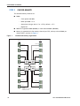
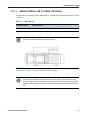
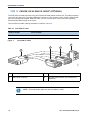
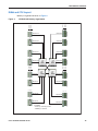
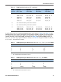
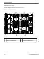
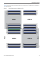
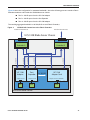
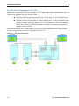
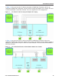
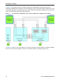
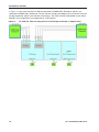
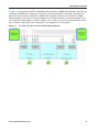
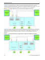
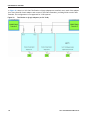
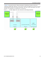
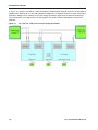
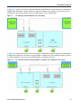
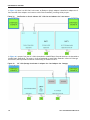
SUPPLEMENTAL MATERIAL
In Figure 37, one port from the VIC 1280 is channeled to 2208XP Fabric Extender A and one is channeled to
2208XP Fabric Extender B. The VIC 1240 slot is empty and adapter slot 2 is empty. The result is 10 Gb of
bandwidth to each Fabric Extender. This is not supported for 2-CPU configurations.
Figure 37
VIC 1280 (VIC 1240 and adapter slot 2 are empty)
In Figure 38, one port from the VIC 1240 is channeled to 2104XP Fabric Extender A and one is channeled to
2104XP Fabric Extender B. The Emulex or QLogic adapter in adapter slot 3 also channels one port to each of
the Fabric Extenders. The result is 20 Gb of bandwidth to each Fabric Extender.
Figure 38
VIC 1240 and Emulex or QLogic Adapter in Adapter Slot 3 (adapter slot 2 empty)
Cisco UCS B420 M3 Blade Server
63
SUPPLEMENTAL MATERIAL
In Figure 39, there is no VIC 1240. In this case, an Emulex or QLogic adapter is installed in adapter slot 3.
Ports A and B of the adapter card connect to the Fabric Extenders, providing 10 Gb per port.
Figure 39
One Emulex or QLogic Adapter (VIC 1240 slot and adapter slot 2 are empty)
In Figure 40, one port from the VIC 1240 is channeled to 2104XP Fabric Extender A and one is channeled to
2104XP Fabric Extender B. The result is 10 Gb of bandwidth to each Fabric Extender. A Cisco UCS Storage
Accelerator (which provides no network connectivity) is installed in slot 2.
Figure 40
64
VIC 1240 (Storage Accelerator in adapter slot 3 and adapter slot 2 empty)
Cisco UCS B420 M3 Blade Server
SUPPLEMENTAL MATERIAL
In Figure 41, one port from the VIC 1240 is channeled to 2104XP Fabric Extender A and one is channeled to
2104XP Fabric Extender B. The result is 10 Gb of bandwidth to each Fabric Extender. Cisco UCS Storage
Accelerators (which provide no network connectivity) are installed in slots 2 and 3. This configuration is not
supported for 2-CPU systems.
Figure 41
VIC 1240 (Storage Accelerators in adapter slots 2 and 3)
In Figure 42, one port from the VIC 1280 is channeled to 2208XP Fabric Extender A and one is channeled to
2208XP Fabric Extender B. The VIC 1240 slot is empty and adapter slot 2 contains a Cisco UCS Storage
Accelerator (which has no network connectivity). The result is 10 Gb of bandwidth to each Fabric Extender.
This configuration is not supported for 2-CPU systems.
Figure 42
VIC 1280 (VIC 1240 slot empty and Cisco UCS Storage Accelerator in adapter slot 2)
Cisco UCS B420 M3 Blade Server
65
SUPPLEMENTAL MATERIAL
In Figure 43, one port from the VIC 1240 is channeled to 2104XP Fabric Extender A and one is channeled to
2104XP Fabric Extender B. The VIC 1280 installed in adapter slot 3 channels one port to each of the Fabric
Extenders. Adapter slot 2 contains a Cisco UCS Storage Accelerator (which has no network connectivity).
This configuration is not supported for 2-CPU systems. The result is 20 Gb of bandwidth to each Fabric
Extender.
Figure 43
66
VIC 1240, VIC 1280, and Cisco UCS Storage Accelerator
Cisco UCS B420 M3 Blade Server
TECHNICAL SPECIFICATIONS
Dimensions and Weight
Table 32 UCS B420 M3 Dimensions and Weight
Parameter
Value
Height
1.95 in. (50 mm)
Width
16.5 in.(419 mm)
Depth
24.4 in. (620 mm)
Weight
■
Base server weight
(no CPUs, no memory, no adapter cards, no USB, 3 baffles, no SD cards, no HDDs, 4 HDD
fillers, no SuperCap, no TFM) = 20.7 lbs (9.4 kg)
■
Minimally configured server
(2 CPUs, 2 DIMMs, MLOM, no adapter cards, with USB, 3 baffles, with 1 SD card, 1 HDD,
HDD fillers, no SuperCap, no TFM) = 24.3 lbs (11.0 kg)
■
Fully configured server
(4 CPUs, 48 DIMMs, MLOM, 2 adapter cards, with USB, 3 baffles, with 2 SD cards, 4 HDDs,
with SuperCap, with TFM) = 34.3 lbs (15.56 kg)
Power Specifications
For configuration-specific power specifications, use the Cisco UCS Power Calculator at:
https://express.salire.com/Go/Cisco/Cisco-UCS-Power-Calculator.aspx
Cisco UCS B420 M3 Blade Server
67
TECHNICAL SPECIFICATIONS
68
Cisco UCS B420 M3 Blade Server