1
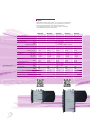
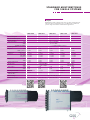
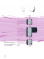
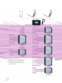
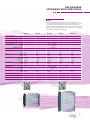
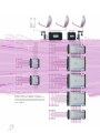
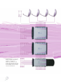
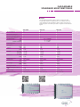
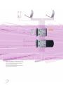
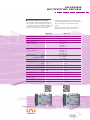
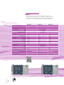
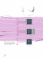
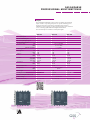
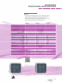
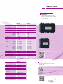
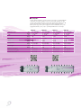
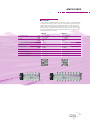
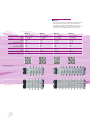
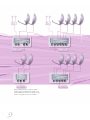
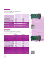
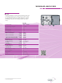
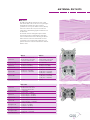
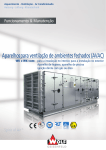
I N STAL L ATIO N
E QUIPM EN T
P ROGRAMME
2012/2013
INDEX
2
Editorial
3
Standard Multiswitches for Single Systems
4
Cascadable Standard Multiswitches
8
Cascadable Multiswitches Unicable
16
Professional Multiswitches for Single Systems
18
Cascadable Professional Multiswitches
20
Power Supply Concept
24
Amplifiers
25
Accessories
28
DiSEqC Multiswitches
30
Wideband Amplifiers
32
Taps and Splitters
34
Antenna Outlets and Accessories
36
Dish Antennas and Accessories
38
LNBs
39
Installation Material
40
Order processing:
Service:
Bettina Wilmerstadt
Margareta Kiss
Phone: +49/9 11/7 03 - 72 09
Fax: +49/9 11/7 03 - 92 10
Email: [email protected]
Phone: +49/9 11/7 03 - 22 21
Fax: +49/9 11/7 03 - 23 26
Email: [email protected]
You will find every product for the installation of Broadband communication
and SAT IF networks in this catalogue. Beginning with the satellite antenna
with the corresponding LNB further to every necessary component of the
satellite IF distribution equipment to the point of wall outlet - everything from
one source. There are every necessary components for the range of broadband
communication installation equipment after the feed-in of the corresponding
signal - this equipment consists of broadband communication amplifiers, taps
and splitters and wall outlets. There is the suitable product for every
application.
Two new multiswitches in the range of satellite IF distribution are added.
There are a 24 and a 32 output multiswitch version with 16 satellite inputs
and 1 terrestrial input. These multiswitches are featured with the well-known
advantages of the current multiswitch portfolio: low power consumption and
first-class isolation values.
For the first time you will find for the most of the products a QR code.
You can get to the relevant product site on our homepage and download e.g.
the manual or assembly instruction for this product.
We are sure that you can equip your distribution network with every necessary
components from GSS.
On behalf of the Board of Directors
Fred Huebner
3
5 inputs
Multiswitches with 4 SAT IF inputs and one active terrestrial input.
The latter can be attenuated by up to 10 dB and also switched to
passive stage which allows return-channel applications.
A 22-kHz signal generator can be switched on for controlling
Quad LNBs with integrated multiswitch.
SDSP 504
SDSP 506
SDSP 508
SDSP 512
SDSP 516
No. of SAT inputs
4
4
4
4
4
No. of terrestrial inputs
1
1
1
1
1
No. of outputs
4
6
8
12
16
Frequency range
SAT
TERR
RETURN CHANNEL
950 – 2200 MHz
87 – 862 MHz
5 – 65 MHz (if TERR is passive!)
22-kHz generator
Tap loss
•
SAT
TERR (passive)
Distribution
1 dB
15 dB
1 dB
15 dB
•
3 dB
18 dB
•
3 dB
18 dB
3 dB
0 dB
0 dB
-3 dB
-3 dB
> 30 dB
> 25 dB
> 20 dB
10 dB
10 dB
> 30 dB
> 25 dB
> 20 dB
10 dB
10 dB
> 30 dB
> 25 dB
> 20 dB
10 dB
10 dB
> 30 dB
> 25 dB
> 20 dB
10 dB
10 dB
12 dB
15 dB
15 dB
18 dB
18 dB
7 dB
6 dB
7 dB
6 dB
max. 101 dBμV
max. 97 dBμV
7 dB
6 dB
7 dB
6 dB
7 dB
6 dB
Feeding for receiver
< 65 mA
< 65 mA
< 65 mA
< 65 mA
< 65 mA
Power consumption without LNB
4.7 W
4.7 W
4.7 W
4.7 W
4.7 W
225x125x60
225x125x60
Return loss
Hor./Vert.
SAT/TERR
Port/Port
SAT
TERR
Return-channel loss
Output level
Noise figure
SAT
TERR
SAT
TERR
Mains voltage
Dimensions in mm
4
•
> 30 dB
> 25 dB
> 20 dB
10 dB
10 dB
Isolation
TERR (active)
1 dB
12 dB
•
100 – 230 V AC, 50/60 Hz
225x125x60
225x215x60
225x215x60
STANDARD MULTISWITCHES
FOR SINGLE S YSTEMS
9 inputs
Multiswitches with 8 SAT IF inputs and one active terrestrial input.
The latter can be attenuated by up to 10 dB and also switched to
passive stage which allows return-channel applications.
A 22-kHz signal generator can be switched on for controlling
Quad LNBs with integrated multiswitch.
SDSP 904
SDSP 906
SDSP 908
SDSP 912
SDSP 916
SDSP 924
SDSP 932
No. of SAT inputs
8
8
8
8
8
8
8
No. of terrestrial inputs
1
1
1
1
1
1
1
No. of outputs
4
6
8
12
16
24
32
Frequency range
SAT
TERR
RETURN CHANNEL
950 – 2200 MHz
87 – 862 MHz
5 – 65 MHz (if TERR is passive!)
22-kHz generator
Tap loss
•
SAT
TERR (passive)
Distribution
3 dB
15 dB
•
3 dB
15 dB
•
5 dB
18 dB
•
5 dB
18 dB
•
•
0 dB
28 dB
0 dB
28 dB
3 dB
0 dB
0 dB
-3 dB
-3 dB
0 dB
0 dB
> 30 dB
> 25 dB
> 20 dB
10 dB
10 dB
> 30 dB
> 25 dB
> 20 dB
10 dB
10 dB
> 30 dB
> 25 dB
> 20 dB
10 dB
10 dB
> 30 dB
> 25 dB
> 20 dB
10 dB
10 dB
> 30 dB
> 25 dB
> 20 dB
10 dB
10 dB
> 30 dB
> 25 dB
> 20 dB
10 dB
10 dB
> 30 dB
> 25 dB
> 20 dB
10 dB
10 dB
12 dB
15 dB
15 dB
18 dB
18 dB
28 dB
28 dB
7 dB
6 dB
7 dB
6 dB
max. 101 dBμV
max. 97 dBμV
7 dB
7 dB
6 dB
6 dB
7 dB
6 dB
7 dB
8 dB
Feeding for receiver
< 65 mA
< 65 mA
< 65 mA
< 65 mA
< 65 mA
< 30 mA
< 30 mA
Power consumption without LNB
4.7 W
4.7 W
4.7 W
4.7 W
4.7 W
9W
9W
Isolation
Return loss
TERR (active)
3 dB
12 dB
•
Hor./Vert.
SAT/TERR
Port/Port
SAT
TERR
Return-channel loss
Output level
Noise figure
Mains voltage
Dimensions in mm
SAT
TERR
SAT
TERR
max. 95 dBμV
max. 95 dBμV
7 dB
8 dB
100 – 230 V AC, 50/60 Hz
260x125x60 260x125x60 260x125x60 260x215x60 260x215x60 185x290x60 185x290x60
5
13 inputs
Multiswitches with 12 SAT IF inputs and one active terrestrial input.
The latter can be attenuated by up to 10 dB and also switched to
passive stage which allows return-channel applications.
SDSP 1308
SDSP 1312
SDSP 1316
No. of SAT inputs
12
12
12
No. of terrestrial inputs
1
1
1
No. of outputs
8
12
16
Frequency range
SAT
TERR
RETURN CHANNEL
950 – 2200 MHz
87 – 862 MHz
5 – 65 MHz (if TERR is passive!)
22-kHz generator
Tap loss
—
SAT
TERR (passive)
—
5 dB
15 dB
7 dB
18 dB
7 dB
18 dB
0 dB
-3 dB
-3 dB
> 30 dB
> 25 dB
> 20 dB
10 dB
10 dB
> 30 dB
> 25 dB
> 20 dB
10 dB
10 dB
> 30 dB
> 25 dB
> 20 dB
10 dB
10 dB
15 dB
18 dB
18 dB
7 dB
6 dB
max. 101 dBμV
max. 97 dBμV
7 dB
6 dB
7 dB
6 dB
Feeding for receiver
< 65 mA
< 65 mA
< 65 mA
Power consumption
without LNB
3.5 W
3.5 W
3.5 W
Distribution
Isolation
Return loss
TERR (active)
Hor./Vert.
SAT/TERR
Port/Port
SAT
TERR
Return-channel loss
Output level
Noise figure
SAT
TERR
SAT
TERR
Mains voltage
Dimensions in mm
6
—
100 – 230 V AC, 50/60 Hz
340 x 125 x 60
340 x 215 x 60
340 x 215 x 60
STANDARD MULTISWITCHES
FOR SINGLE S YSTEMS
17 inputs
Multiswitches with 16 SAT IF inputs and one active terrestrial input.
The latter can be attenuated by up to 10 dB and also switched to
passive stage which allows return-channel applications.
SDSP 1708
SDSP 1712
SDSP 1716
SDSP 1724
SDSP 1732
No. of SAT inputs
16
16
16
16
16
No. of terrestrial inputs
1
1
1
1
1
No. of outputs
8
12
16
24
32
Frequency range
SAT
TERR
RETURN CHANNEL
950 – 2200 MHz
87 – 862 MHz
5 – 65 MHz (if TERR is passive!)
22-kHz generator
Tap loss
—
SAT
TERR (passive)
Distribution
7 dB
18 dB
—
7 dB
18 dB
—
—
0 dB
28 dB
0 dB
28 dB
0 dB
-3 dB
-3 dB
0 dB
0 dB
> 30 dB
> 25 dB
> 20 dB
10 dB
10 dB
> 30 dB
> 25 dB
> 20 dB
10 dB
10 dB
> 30 dB
> 25 dB
> 20 dB
10 dB
10 dB
> 30 dB
> 25 dB
> 20 dB
10 dB
10 dB
> 30 dB
> 25 dB
> 20 dB
10 dB
10 dB
15 dB
18 dB
18 dB
28 dB
7 dB
6 dB
max. 101 dBμV
max. 97 dBμV
7 dB
6 dB
7 dB
6 dB
7 dB
8 dB
Feeding for receiver
< 65 mA
< 65 mA
< 65 mA
< 30 mA
< 30 mA
Power consumption
without LNB
3.5 W
3.5 W
3.5 W
9W
9W
340 x 125 x 60
340 x 215 x 60
Isolation
Return loss
TERR (active)
5 dB
15 dB
—
Hor./Vert.
SAT/TERR
Port/Port
SAT
TERR
Return-channel loss
Output level
Noise figure
SAT
TERR
SAT
TERR
Mains voltage
Dimensions in mm
28 dB
max. 95 dBμV
max. 95 dBμV
7 dB
8 dB
100 – 230 V AC, 50/60 Hz
340 x 215 x 60
220 x 290 x 60
220 x 290 x 60
7
Satellite installation for digital and analogue
reception of one satellite (e.g. ASTRA 19.2°)
with terrestrial feed for up to 32 participants.
The power supply unit can flexibly connected
to any of the three multiswitches.
8
C AS C ADAB L E
STANDARD MULTISWITCHES
5 inputs
The cascadable multiswitch system consists of components with
loop-through outputs and terminal units to be installed at the end
of the distribution. The multiswitches with 4 SAT IF inputs have an
additional passive terrestrial input which is capable for return-channel
signals. A 22-kHz signal generator can be switched on for controlling
Quad LNBs with integrated multiswitch.
No. of SAT inputs
SDC 504
SDC 508
SDC 516
4
4
4
No. of terrestrial inputs
1
1
1
No. of loop-through outputs
5
5
5
No. of receiver outputs
Frequency range
4
8
SAT
TERR
RETURN CHANNEL
22-kHz generator
Through loss
SAT
TERR
Tap loss
SAT
TERR
Isolation
Hor./Vert.
SAT/TERR
Port/Port
Return loss
SAT
TERR
Return-channel loss
Output level
SAT
TERR
Noise figure
SAT
TERR
Feeding for receiver
Power consumption
without LNB
Mains voltage
Dimensions in mm
•
2 dB
2 dB
1 dB
20 dB
> 30 dB
> 25 dB
> 20 dB
10 dB
10 dB
20 dB
16
950 – 2200 MHz
87 – 862 MHz
5 – 65 MHz
•
2 dB
2 dB
1 dB
23 dB
> 30 dB
> 25 dB
> 20 dB
10 dB
10 dB
23 dB
•
4 dB
4 dB
3 dB
25 dB
> 30 dB
> 25 dB
> 20 dB
10 dB
10 dB
25 dB
max. 101 dBμV
passive
7 dB
passive
< 65 mA
7 dB
passive
< 65 mA
7 dB
passive
< 65 mA
1.5 W
1.5 W
1.5 W
125x135x60
125x135x60
via SDP 900
125x225x60
9
Satellite installation for digital and analogue
reception of two satellites (e.g. ASTRA 19.2°
and Eutelsat 13°) with terrestrial feed for up
to 76 participants. The input signals are fed
via a SAT IF amplifier.
10
C AS C ADAB L E
STANDARD MULTISWITCHES
9 inputs
The cascadable multiswitch system consists of components with
loop-through outputs and terminal units to be installed at the end of
the distribution. The multiswitches with 8 SAT IF inputs have an
additional passive terrestrial input which is capable for return-channel
signals. A 22-kHz signal generator can be switched on for controlling
Quad LNBs with integrated multiswitch.
SDC 904
SDC 906
SDC 908
SDC 912
SDC 916
No. of SAT inputs
8
8
8
8
8
No. of terrestrial inputs
1
1
1
1
1
No. of loop-through outputs
9
9
9
9
9
No. of receiver outputs
4
6
8
12
16
Frequency range
SAT
TERR
RETURN CHANNEL
950 – 2200 MHz
87 – 862 MHz
5 – 65 MHz
22-kHz generator
Through loss
Tap loss
Isolation
Return loss
Return-channel loss
Output level
Noise figure
Feeding for receiver
•
SAT
TERR
SAT
TERR
Hor./Vert.
SAT/TERR
Port/Port
SAT
TERR
•
•
•
•
2 dB
2 dB
3 dB
20 dB
> 30 dB
> 25 dB
> 20 dB
10 dB
10 dB
2 dB
2 dB
3 dB
23 dB
> 30 dB
> 25 dB
> 20 dB
10 dB
10 dB
2 dB
2 dB
3 dB
23 dB
> 30 dB
> 25 dB
> 20 dB
10 dB
10 dB
4 dB
4 dB
5 dB
25 dB
> 30 dB
> 25 dB
> 20 dB
10 dB
10 dB
4 dB
4 dB
5 dB
25 dB
> 30 dB
> 25 dB
> 20 dB
10 dB
10 dB
20 dB
23 dB
23 dB
25 dB
25 dB
7 dB
passive
max. 101dBμV
passive
7 dB
passive
7 dB
passive
7 dB
passive
< 65 mA
< 65 mA
< 65 mA
< 65 mA
SAT
TERR
SAT 7 dB
TERR passive
< 65 mA
Power consumption without LNB 1.5 W
1.5 W
1.5 W
1.5 W
1.5 W
Mains voltage
via SDP 900
via SDP 900
via SDP 900
via SDP 900
via SDP 900
Dimensions in mm
160x135x60
160x135x60
160x135x60
160x225x60
160x225x60
11
Satellite installation for digital and analogue
reception of up to three satellites (e.g. ASTRA 19.2°,
Eutelsat 13° and Turksat) with terrestrial feed for up
to 72 participants. The input signals are fed via two
SAT IF amplifiers.
12
C AS C ADAB L E
STANDARD MULTISWITCHES
13 inputs
The cascadable multiswitch system consists of components with
loop-through outputs and terminal units to be installed at the
end of the distribution. The multiswitches with 12 SAT IF inputs
have an additional passive terrestrial input which is capable for
return-channel signals.
SDC 1308
SDC 1312
SDC 1316
No. of SAT inputs
12
12
12
No. of terrestrial inputs
1
1
1
No. of loop-through outputs
13
13
13
No. of receiver outputs
8
12
Frequency range
SAT
TERR
RETURN CHANNEL
22-kHz generator
Through loss
16
950 – 2200 MHz
87 – 862 MHz
5 – 65 MHz
—
—
—
2 dB
2 dB
5 dB
23 dB
> 30 dB
> 25 dB
> 20 dB
10 dB
10 dB
4 dB
4 dB
7 dB
25 dB
> 30 dB
> 25 dB
> 20 dB
10 dB
10 dB
4 dB
4 dB
7 dB
25 dB
> 30 dB
> 25 dB
> 20 dB
10 dB
10 dB
23 dB
25 dB
25 dB
max. 101dBμV
passive
7 dB
passive
max. 101dBμV
passive
7 dB
passive
max. 101dBμV
passive
7 dB
passive
Feeding for receiver
< 65 mA
< 65 mA
< 65 mA
Power consumption
without LNB
1.5 W
1.5 W
1.5 W
Mains voltage
via SDP 1700
via SDP 1700
via SDP 1700
Dimensions in mm
240 x 135 x 60
240 x 225 x 60
240 x 225 x 60
Tap loss
Isolation
Return loss
SAT
TERR
SAT
TERR
Hor./Vert.
SAT/TERR
Port/Port
SAT
TERR
Return-channel loss
Output level
Noise figure
SAT
TERR
SAT
TERR
13
Satellite installation for digital and
analogue reception of up to four
satellites (e.g. ASTRA 19.2°,
ASTRA 23.5°, Eutelsat 13° and
Turksat) with terrestrial feed for up
to 36 participants. The power supply
unit can flexibly connected to any
of the three multiswitches.
14
C AS C ADABL E
STANDARD MULTISWITCHES
17 inputs
The cascadable multiswitch system consists of components with
loop-through outputs and terminal units to be installed at the end
of the distribution. The multiswitches with 16 SAT IF inputs have an
additional passive terrestrial input which is capable for return-channel
signals.
SDC 1708
SDC 1712
SDC 1716
No. of SAT inputs
16
16
16
No. of terrestrial inputs
1
1
1
No. of loop-through outputs
17
17
17
No. of receiver outputs
8
12
Frequency range
SAT
TERR
RETURN CHANNEL
22-kHz generator
Through loss
Tap loss
Isolation
Return loss
16
950 – 2200 MHz
87 – 862 MHz
5 – 65 MHz
—
SAT
TERR
SAT
TERR
Hor./Vert.
SAT/TERR
Port/Port
SAT
TERR
Return-channel loss
2 dB
2 dB
5 dB
23 dB
> 30 dB
> 25 dB
> 20 dB
10 dB
10 dB
—
4 dB
4 dB
7 dB
25 dB
> 30 dB
> 25 dB
> 20 dB
10 dB
10 dB
—
4 dB
4 dB
7 dB
25 dB
> 30 dB
> 25 dB
> 20 dB
10 dB
10 dB
23 dB
25 dB
25 dB
max. 101dBμV
passive
7 dB
passive
max. 101dBμV
passive
7 dB
passive
max. 101dBμV
passive
7 dB
passive
Feeding for receiver
< 65 mA
< 65 mA
< 65 mA
Power consumption without
LNB
1.5 W
1.5 W
1.5 W
Mains voltage
via SDP 1700
via SDP 1700
via SDP 1700
Dimensions in mm
240 x 135 x 60
240 x 225 x 60
240 x 225 x 60
Output level
Noise figure
SAT
TERR
SAT
TERR
15
1-4
1-4
Satellite installation for digital reception of one
satellite (e.g. ASTRA 19.2°) with terrestrial feed
for up to 16 participants with receiver which
support the Unicable standard.
The power supply unit can flexibly connected to
any of the both multiswitches.
16
SRS 205
1-8
C AS C ADAB L E
MULTISWITCHES UNIC ABLE
A 22-kHz signal generator can be switched on for
controlling Quad LNBs with integrated multiswitch.
Cascadable multiswitches Unicable
The cascadable multiswitch system unicable consists of satellite and terrestrial inputs as well as
loop-through outputs. An optional switching power
supply can be used for low current consumption
and noise-free transmission of the signals.
The terrestrial input is suitable for return-path
signals.
Both outputs can be combined with the splitter
SRS 205 for creating a rope for 8 receivers.
SDUC 502
SDUC 902
No. of SAT inputs
4
8
No. of terrestrial inputs
1
1
No. of loop-through outputs
5
9
Output frequencies
output 1/chanel ID
1284 MHz / 0
1400 MHz / 1
1516 MHz / 2
1632 MHz / 3
1748 MHz / 4
1864 MHz / 5
1980 MHz / 6
2096 MHz / 7
950 – 2200 MHz
87 – 862 MHz
5 – 65 MHz
Output frequencies
output 2/channel ID
Frequency range
SAT
TERR
RETURN CHANNEL
•
22-kHz generator
Through loss
Tap loss
•
SAT 2 dB
TERR 3.5 dB
TERR (passive) 10 dB
2 dB
3.5 dB
10 dB
SAT 14 dB
14 dB
SAT 10 dB
TERR 10 dB
TERR 10 dB
10 dB
10 dB
10 dB
Gain
Return loss
Return-channel loss
Feeding for receiver
< 30 mA
< 30 mA
Power consumption
without LNB
7W
7W
via SDP 900
Mains voltage
Dimensions in mm
135 x 160 x 60
135 x 160 x 60
17
5 inputs
Multiswitches with 4 SAT IF inputs and one active terrestrial input.
The latter can be attenuated by up to 10 dB and also switched to passive
stage with allows return-path applications. A 22-kHz signal generator can
be switched on for controlling Quad LNBs with integrated multiswitch.
PDSP 504
PDSP 506
PDSP 508
No. of SAT inputs
4
4
4
No. of terrestrial inputs
1
1
1
No. of outputs
4
6
Frequency range
SAT
TERR
RETURN CHANNEL
22-kHz generator
Tap loss
•
SAT
TERR (passive)
Gain
Isolation
Return loss
TERR (active)
Hor./Vert.
SAT/TERR
Port/Port
SAT
TERR
Return-channel loss
Output level
Noise figure
SAT
TERR
SAT
TERR
0 dB
17 dB
•
0 dB
17 dB
•
0 dB
17 dB
0 dB
0 dB
0 dB
> 30 dB
> 25 dB
> 20 dB
10 dB
10 dB
> 30 dB
> 25 dB
> 20 dB
10 dB
10 dB
> 30 dB
> 25 dB
> 20 dB
10 dB
10 dB
17 dB
17 dB
17 dB
max. 101 dBμV
max. 97 dB
7 dB
6 dB
7 dB
6 dB
7 dB
6 dB
Feeding for receiver
< 65 mA
< 65 mA
< 65 mA
Power consumption without LNB
4.7 W
4.7 W
4.7 W
Mains voltage
Dimensions in mm
18
8
950 – 2200 MHz
87 – 862 MHz
5 – 65 MHz
100 – 230 V AC / 50/60 Hz
230 x 133 x 55
230 x 133 x 55
230 x 133 x 55
P ROF ES S IONAL M ULTISW ITC H E S
FOR SINGLE S YSTEMS
9 inputs
Multiswitches with 8 SAT IF inputs and one active terrestrial input.
The latter can be attenuated by up to 10 dB and also switched to
passive stage with allows return-path applications. A 22-kHz signal
generator can be switched on for controlling Quad LNBs with
integrated multiswitch.
PDSP 904
PDSP 906
PDSP 908
No. of SAT inputs
8
8
8
No. of terrestrial inputs
1
1
1
No. of outputs
4
6
Frequency range
SAT
TERR
RETURN CHANNEL
22-kHz generator
Tap loss
8
950 – 2200 MHz
87 – 862 MHz
5 – 65 MHz
•
SAT
TERR (passive)
Gain
Isolation
Return loss
TERR (active)
Hor./Vert.
SAT/TERR
Port/Port
SAT
TERR
Return-channel loss
Output level
Noise figure
SAT
TERR
SAT
TERR
0 dB
17 dB
•
0 dB
17 dB
•
0 dB
17 dB
0 dB
0 dB
0 dB
> 30 dB
> 25 dB
> 20 dB
10 dB
10 dB
> 30 dB
> 25 dB
> 20 dB
10 dB
10 dB
> 30 dB
> 25 dB
> 20 dB
10 dB
10 dB
17 dB
17 dB
17 dB
max. 101 dBμV
max. 97 dB
7 dB
6 dB
7 dB
6 dB
7 dB
6 dB
Feeding for receiver
< 65 mA
< 65 mA
< 65 mA
Power consumption without LNB
4.7 W
4.7 W
4.7 W
Mains voltage
Dimensions in mm
100 – 230 V AC / 50/60 Hz
230 x 133 x 55
230 x 133 x 55
230 x 133 x 55
19
Satellite installation for digital and analogue
reception of one satellite (e.g. ASTRA 19.2°)
with terrestrial feed for up to 18 participants.
The power supply unit can flexibly connected
to any of the three multiswitches.
20
C AS C ADAB L E
PROF ES S IONAL M ULTISW ITC H E S
5 inputs
The cascadable multiswitch system consists of satellite and terrestrial
inputs as well as loop-through outputs. An optional switching power
supply can be used for low current consumption and noise-free
transmission of the signals. A 22-kHz signal generator can be switched
on for controlling Quad LNBs with integrated multiswitch.
The terrestrial input is suitable for return-path signals.
PDC 504
PDC 506
PDC 508
No. of SAT inputs
4
4
4
No. of terrestrial inputs
1
1
1
No. of loop-through outputs
5
5
5
No. of receiver outputs
4
6
Frequency range
SAT
TERR
RETURN CHANNEL
22-kHz generator
Through loss
Tap loss
Isolation
Return loss
•
SAT
TERR
SAT
TERR
Hor./Vert.
SAT/TERR
Port/Port
SAT
TERR
Return-channel loss
Output level
8
950 – 2200 MHz
87 – 862 MHz
5 – 65 MHz
•
3 dB
3 dB
0 dB
23 dB
> 30 dB
> 25 dB
> 20 dB
10 dB
10 dB
3 dB
3 dB
0 dB
23 dB
> 30 dB
> 25 dB
> 20 dB
10 dB
10 dB
23 dB
23 dB
23 dB
SAT
TERR
Noise figure
•
3 dB
3 dB
0 dB
23 dB
> 30 dB
> 25 dB
> 20 dB
10 dB
10 dB
max. 101 dBμV
passive
7 dB
7 dB
Feeding for receiver
SAT 7 dB
< 65 mA
< 65 mA
< 65 mA
Power consumption without LNB
1.5 W
1.5 W
1.5 W
Mains voltage
Dimensions in mm
via PDP 900
165 x 133 x 55
165 x 133 x 55
165 x 133 x 55
21
Satellite installation for digital and analogue
reception of two satellites (e.g. ASTRA 19.2°
and Eutelsat 13°) with terrestrial feed for up
to 42 participants. The input signals are fed
via a SAT IF amplifier.
22
C AS C ADAB L E
PROF ES S IONAL M ULTISW ITC H E S
9 inputs
The cascadable multiswitch system consists of satellite and terrestrial
inputs as well as loop-through outputs. An optional switching power
supply can be used for low current consumption and noise-free
transmission of the signals. A 22-kHz signal generator can be switched
on for controlling Quad LNBs with integrated multiswitch.
The terrestrial input is suitable for return-path signals.
PDC 904
PDC 906
PDC 908
No. of SAT inputs
8
8
8
No. of terrestrial inputs
1
1
1
No. of loop-through outputs
9
9
9
No. of receiver outputs
4
6
Frequency range
SAT
TERR
RETURN CHANNEL
22-kHz generator
Through loss
Tap loss
Isolation
Return loss
•
SAT
TERR
SAT
TERR
Hor./Vert.
SAT/TERR
Port/Port
SAT
TERR
Return-channel loss
Output level
8
950 – 2200 MHz
87 – 862 MHz
5 – 65 MHz
•
3 dB
3 dB
0 dB
23 dB
> 30 dB
> 25 dB
> 20 dB
10 dB
10 dB
3 dB
3 dB
0 dB
23 dB
> 30 dB
> 25 dB
> 20 dB
10 dB
10 dB
23 dB
23 dB
23 dB
SAT
TERR
Noise figure
•
3 dB
3 dB
0 dB
23 dB
> 30 dB
> 25 dB
> 20 dB
10 dB
10 dB
max. 101 dBμV
passive
7 dB
7 dB
Feeding for receiver
SAT 7 dB
< 65 mA
< 65 mA
< 65 mA
Power consumption without LNB
1.5 W
1.5 W
1.5 W
Mains voltage
Dimensions in mm
via PDP 900
165 x 133 x 55
165 x 133 x 55
165 x 133 x 55
23
POWER SUPPLY CONCEPT
The idea of the GSS-SAT IF distribution
system allows a flexible positioning of the
power supply units. As a power supply unit
can be connected to each component of
the SAT IF distribution to feed each other
device of the distribution system like
multiswitches, amplifiers or LNBs it can be
placed wherever you want and wherever
necessary.
24
AM PLIF IE RS
SAT IF Amplifier
The amplifiers SDA 900 and SDA 500
can be used for huge distribution networks.
These types have 9 resp. 5 inputs and
18 resp. 10 outputs.
SDA 500
SDA 900
No. of SAT inputs
4
8
No. of terrestrial inputs
1
1
No. of outputs
SAT
TERR
Frequency range
SAT
TERR
Gain
SAT LINE
SAT TAP
TERR LINE
TERR TAP
8
2
950 - 2200 MHz
40 - 862 MHz
32 dB
25 dB
25 dB
15 dB
16
2
950 - 2200 MHz
40 - 862 MHz
32 dB
25 dB
25 dB
15 dB
Isolation
> 70 dB
> 70 dB
Attenuation
Slope
Output level
– IMA 3 –
0 … 15 dB
0 … 7 dB
max. 114 dBμV
max. 107 dBμV
max. 114 dBμV
max. 104 dBμV
max. 112 dBμV
max. 105 dBμV
max. 112 dBμV
max. 102 dBμV
0 … 15 dB
0 … 7 dB
max. 114 dBμV
max. 107 dBμV
max. 114 dBμV
max. 104 dBμV
max. 112 dBμV
max. 105 dBμV
max. 112 dBμV
max. 102 dBμV
Noise figure
8 dB
8 dB
Return loss
10 dB
10 dB
Power supply *)
15 V DC
15 V DC
Current consumption
750 mA
750 mA
Ambient temperature
-20° … +50° C
-20° … +50° C
Dimensions approx. in mm
107 x 142 x 80
193 x 142 x 80
Output level
– IMA 2 –
SAT LINE
SAT TAP
TERR LINE
TERR TAP
SAT LINE
SAT TAP
TERR LINE
TERR TAP
*) via delivered power supply unit
SDA 15
No. of SAT inputs
4
No. of SAT outputs
4
Frequency range
950 ... 2200 MHz
Gain
+ 14,5 dB
Isolation
> 70 dB
Attenuation
0 ... -10 dB
Plugging on Amplifier SDA 15
Plugging on amplifier for 4 SAT IF inputs,
gain 14.5 dB
max. 103 dBμV
(35 dB IMA 3 Ord.)
Return loss
10 dB
Current consumption SDA 15 ca. 40 mA
Output level
Current consumption LNC
max. 400 mA
Ambient temperature
-20°C ... +50°C
Dimensions approx. in mm
36 x 67 x 62
25
Multi-Amplifier
At huge SAT IF distribution systems it may be necessary to use multi-amplifier
components for tapped signals in order to level the SAT IF signals. For this
case the GSS models with 5 and 9 inputs and outputs with 12 dB and 20 dB
gain are the right choice. They are fed by the power supply units of the
SAT IF system (e.g. via the power supply unit of the multiswitch). The power
supply unit SDP 152 (15 V/2 A) is optionally available if it is necessary!
Frequency range
Gain
SAT
TERR
SAT
TERR
Attenuation
TERR
Return loss
SAT
TERR
SAT
TERR
SAT
TERR
Output level
Noise figure
SDA 512
SDA 520
SDA 912
SDA 920
950 – 2200 MHz
10 – 862 MHz
8 – 12 dB
12 dB
950 – 2200 MHz
10 – 862 MHz
15 – 20 dB
20 dB
950 – 2200 MHz
10 – 862 MHz
8 – 12 dB
12 dB
950 – 2200 MHz
10 – 862 MHz
15 – 20 dB
20 dB
—
10 dB
10 dB
max. 110 dBμV
max. 106 dBμV
7 dB
6 dB
0 – 15 dB
10 dB
10 dB
max. 113 dBμV
max. 106 dBμV
7 dB
6 dB
—
10 dB
10 dB
max. 110 dBμV
max. 106 dBμV
7 dB
6 dB
0 – 15 dB
10 dB
10 dB
max. 113 dBμV
max. 106 dBμV
7 dB
6 dB
Current consumption
15 V/180 mA
15 V/250 mA
15 V/220 mA
15 V/450 mA
Remote current supply
Dimensions in mm
max. 1000 mA
145 x 71 x 35
max. 1000 mA
145 x 71 x 35
max. 1000 mA
210 x 71 x 35
max. 1000 mA
210 x 71 x 35
26
AM P LIF IE RS
Multi-Amplifier
At huge SAT IF distribution systems it may be necessary to use multi-amplifier
components for tapped signals in order to level the SAT IF signals. There are
models with 5 and 9 inputs and outputs with a gain of 20 dB. Every input
(TERR + SAT) is equipped with an attenuation controller by 15 dB. They are
fed by the power supply units of the SAT IF system (e.g. via the power supply
unit of the multiswitch). The power supply unit SDP 152 (15 V/2 A) is optionally available if it is necessary!
SDA 521
SDA 921
950 – 2200 MHz
10 – 862 MHz
15 – 20 dB
20 dB
950 – 2200 MHz
10 – 862 MHz
15 – 20 dB
20 dB
Attenuation control
0 – 15 dB
0 – 15 dB
Return loss
12 dB
Frequency range
Gain
Output level
SAT
TERR
SAT
TERR
SAT 111 dBμV
TERR 109 dBμV
12 dB
111 dBμV
109 dBμV
Noise figure
5 dB
5 dB
Current consumption
15 V / 250 mA
15 V / 500 mA
Remote current supply
max. 1000 mA
max. 1000 mA
Dimensions in mm
145 x 71 x 35
210 x 71 x 35
27
Multi-Tap
Multi-Taps are necessary for tapping the signals at huge
SAT IF distribution systems. There are models with 5
loop-through and tap outputs available resp. 9 loopthrough and tap outputs. The power supply unit SDP 152
(15 V/2 A) is optionally available if it is necessary!
SDM 512
SDM 912
SDM 522
SDM 922
Frequency range
SAT
TERR
Tap loss
SAT
TERR
RETURN CHANNEL
Through loss
SAT
TERR
RETURN CHANNEL
Return loss
SAT
TERR
950 – 2200 MHz
10 – 862 MHz
12 – 16 dB
12 dB
12 dB
1.8 dB
2 dB
2 dB
10 dB
10 dB
950 – 2200 MHz
10 – 862 MHz
12 – 16 dB
12 dB
12 dB
1.8 dB
2 dB
2 dB
10 dB
10 dB
950 – 2200 MHz
10 – 862 MHz
2 x 11 – 17 dB
2 x 15 dB
2 x 15 dB
2 – 3 dB
1 dB
1 dB
10 dB
10 dB
950 – 2200 MHz
10 – 862 MHz
2 x 11 – 17 dB
2 x 15 dB
2 x 15 dB
2 – 3 dB
1 dB
1 dB
10 dB
10 dB
Remote current supply
max. 1000 mA
max. 1000 mA
max. 1000 mA
max. 1000 mA
Dimensions in mm
145 x 71 x 35
210 x 71 x 35
199 x 98 x 35
254 x 98 x 35
28
AC C ES S OR I E S
Multi Splitter
Multi splitter are necessary for splitting the satellite signals
at the end of a satellite IF line. There are models with double
5 and 9 splitting outputs. The power supply unit SDP 152
(15 V/2 A) is optionally available if it is necessary!
SDS 526
SDS 926
950 – 2200 MHz
5 – 862 MHz
2 x 6 dB
2 x 4 dB
950 – 2200 MHz
5 – 862 MHz
2 x 6 dB
2 x 4 dB
Isolation
> 30 dB
> 30 dB
Return loss
12 dB
12 dB
Frequency range
SAT
TERR
SAT
TERR
Split-loss
Remote current supply
max 1000 mA
max 1000 mA
Dimensions in mm
145 x 71 x 35
210 x 71 x 35
Power Supply Unit for SDC, SDT and SDUC
SDP 900
for SDC/SDT/SDUC
5XX – 9XX
100 V … 230 V AC,
50/60 Hz
SDP 1700
for SDC/SDT
13XX – 17XX
100 V … 230 V AC,
50/60 Hz
PDP 900
for PDC
5XX and 9XX
100 V … 230 V AC,
50/60 Hz
18 V DC
15 V DC
18 V DC
Max. output current
1000 mA DC
2000 mA DC
1000 mA DC
Ambient temperature
-20° … + 50° C
-20° … + 50° C
-20° … + 50° C
Dimensions
approx. in mm
122 x 112 x 60
122 x 112 x 60
82 x 133 x 55
Mains voltage
Output voltage
Power Supply Unit for PDC
29
DiSEqC multiswitches are needed for satellite
reception sytems to distribute the signals to one
receiver. With these switches one receiver can get
access to the signals of up to four satellites.
30
DiSEqC MULTISWITCHES
DiSEqC Multiswitches
DiSEqC multiswitches are needed for satellite reception sytems to distribute the
signals to one receiver. With these switches one receiver can get access to the
signals of up to four satellites. They are operated by the connected receiver
without any external power supply. The GSS DiSEqC multiswitches are supplied
with an UV and weather resistant housing which can be mounted either at an
aerial mast or at walls.
No. of SAT inputs
SD 201
SD 301
SD 401
SD 501
2
2
4
4
No. of terrestrial inputs
–
No. of outputs
Frequency range
Through loss
1
SAT 950 – 2400 MHz
TERR
–
SAT 1 dB
TERR
–
1
–
1
1
1
1
950 – 2400 MHz
47 – 862 MHz
2 dB
0,5 dB
950 – 2400 MHz
–
1 dB
–
950 – 2400 MHz
47 – 862 MHz
2,5 dB
0,5 dB
Return loss
> 12 dB
> 12 dB
> 12 dB
> 12 dB
DiSEqC control
DiSEqC 2.0
DiSEqC 2.0
DiSEqC 2.0
DiSEqC 2.0
Isolation
> 30 dB
> 30 dB
> 30 dB
> 30 dB
Linearity
± 1 dB
± 1 dB
± 1 dB
± 1 dB
Control signal
Position
Position
Position/Option
Position/Option
Remote current supply
max. 700 mA
max. 700 mA
max. 700 mA
max. 700 mA
Current consumption
< 30 mA
< 30 mA
< 30 mA
< 30 mA
50 x 45 x 18
80 x 45 x 18
80 x 45 x 18
90 x 45 x 18
75 x 75 x 45
105 x 75 x 45
105 x 75 x 45
105 x 75 x 45
97 g
133 g
136 g
141 g
Dimensions without weather
resistant housing in mm
Dimensions with weather
resistant housing in mm
Weight
31
AR 4218, AR 4298
Distribution amplifiers for single and master antenna systems.
Frequency range up to 862 MHz. Output adjustable with variable
level controller. 230 V mains voltage.
AR 4218
AR 4298
Frequency range
40 – 862 MHz
40 – 862 MHz
Gain
21 dB
29 dB
Noise figure typ.
6 dB
6 dB
Output level, IMR = 60 dB
IMR 2 acc. EN 50083-3
IMR 3 acc. EN 50083-3
IMR 3 acc. EN 50083-5
CSO Cenelec 42 channels 862 MHz
CTB Cenelec 42 channels 862 MHz
100 dBμV
107 dBμV
113 dBμV
97 dBμV
100 dBμV
105 dBμV
109 dBμV
115 dBμV
101 dBμV
101 dBμV
Attenuator
0 to -20 dB
0 to -20 dB
Mains voltage (50 - 60 Hz)
230 V AC
230 V AC
Power consumption
3W
5W
RF connectors
F connectors
F connectors
Weight
approx. 700 g
approx. 700 g
Dimensions (W x H x D)
170 x 90 x 50 mm
170 x 90 x 50 mm
AR 5218, AR 5298
Distribution amplifiers for single and master antenna systems.
Frequency range up to 862 MHz. Return-path up to 65 MHz either
active or passive switchable. Output level and equalization adjustable
with variable controllers. 230 V mains voltage.
AR 5218
AR 5298
Frequency range
85 – 862 MHz
85 – 862 MHz
Frequency range return-path
5 – 65 MHz
5 – 65 MHz
Gain
21 dB
29 dB
Gain return-path
19 dB
24 dB
Noise figure typ.
6 dB
6 dB
100 dBμV
102 dBμV
107 dBμV
107 dBμV
113 dBμV
113 dBμV
97 dBμV
100 dBμV
105 dBμV
102 dBμV
109 dBμV
107 dBμV
115 dBμV
113 dBμV
101 dBμV
101 dBμV
Output level, IMR = 60 dB
IMR 2 acc. EN 50083-3
forward
return
IMR 3 acc. EN 50083-3
forward
return
IMR 3 acc. EN 50083-5
forward
return
CSO Cenelec 42 channels 862 MHz
CTB Cenelec 42 channels 862 MHz
Attenuator
0 to -20 dB
0 to -20 dB
Adjustable line equalization
0 to 18 dB
0 to 18 dB
Mains voltage (50 – 60 Hz)
230 V AC
230 V AC
Power consumption
4.5 W
6W
RF connectors
F connectors
F connectors
Weight
approx. 700 g
approx. 700 g
Dimesions (W x H x D)
170 x 90 x 50 mm
170 x 90 x 50 mm
32
W IDEBAND AM PLIF IE RS
AR 5368
Distribution amplifiers for single and master antenna systems in cast
housing with particulary good cooling properties. Frequency range
up to 862 MHz. Return-path up to 65 MHz either active or passive
switchable. Selection of the level and the equalization via discrete
and switchable attenuation and equalization links. 230 V mains
voltage.
AR 5368
Frequency range
40 (85) – 862 MHz
Frequency range return-path
5 – 65 MHz
Gain
36 dB
Gain return-path
27 dB
Noise figure typ.
5.5 dB
Output level, IMR = 60 dB
IMR 2 acc. EN 50083-3
CSO Cenelec 42 channels 862 MHz
CTB Cenelec 42 channels 862 MHz
forward
return
forward
return
forward
return
114 dBμV
104 dBμV
123 dBμV
115 dBμV
109 dBμV
108 dBμV
Attenuators
at input (2-dB steps)
at input (2-dB steps)
at output
Interstage
forward
return
return
forward
0 to 16 dB
0 to 6 dB/50 dB
0/3/6/9 dB
0/6 dB
Line equalization
at input (2-dB steps)
Interstage slope
Interstage slope
forward
forward
return
0 to 16 dB
0/7 dB
0/3/6 dB
IMR 3 acc. EN 50083-5
Mains voltage (50 – 60 Hz)
180 – 253 V AC
Power consumption
9W
RF connectors
F connectors
Weight
approx. 2.0 kg
Dimensions (W x H x D)
190 x 110 x 80 mm
On our homepage you will find the actual technical datas
for the Wideband Amplifiers.
33
Splitter
SR 812
SR 610
SR 407
SR 305
SR 203
No. of outputs
8
6
4
3
2
Frequency range
5 – 1000 MHz
5 – 1000 MHz
5 – 862 MHz
5 – 862 MHz
5 – 862 MHz
11.0 dB
11.0 dB
12.5 dB
24 dB
24 dB
20 dB
20 dB
18 dB
18 dB
9.3 dB
9.8 dB
10.5 dB
20 dB
22 dB
20 dB
18 dB
18 dB
18 dB
7.4 dB
7.4 dB
7.4 dB
16 dB
23 dB
23 dB
> 14 dB
> 20 dB1)
> 20 dB1)
5.5 dB
5.5 dB
5.5 dB
16 dB
20 dB
20 dB
> 14 dB
20 dB1)
20 dB1)
3.4 dB
3.4 dB
3.4 dB
20 dB
23 dB
23 dB
> 16 dB
20 dB1)
20 dB1)
Connectors
F connector
F connector
F connector
F connector
F connector
Single-Tap
TR 116
TR 112
TR 108
No. of outputs
1
1
1
Frequency range
5 – 862 MHz
5 – 862 MHz
5 – 862 MHz
Connectors
16.0 dB
16.0 dB
16.0 dB
0.8 dB
0.5 dB
0.8 dB
> 14 dB
> 20 dB1)
> 20 dB1)
> 30 dB
> 26 dB
> 26 dB
F connector
12.0 dB
12.0 dB
12.0 dB
1.0 dB
0.7 dB
1.0 dB
> 14 dB
> 20 dB1)
> 20 dB1)
> 30 dB
> 30 dB
> 26 dB
F connector
8.5 dB
8.5 dB
8.5 dB
1.8 dB
1.6 dB
1.8 dB
> 14 dB
> 20 dB1)
> 20 dB1)
> 22 dB
> 30 dB
> 22 dB
F connector
Double-Tap
TR 216
TR 212
TR 208
No. of outputs
2
2
2
Splitt-loss
Isolation
Return-loss
Tap-loss
Through-loss
Return-loss
Directional-loss
5 – 40 MHz
40 – 470 MHz
470 – 862 MHz
5 – 40 MHz
40 – 470 MHz
470 – 862 MHz
5 – 40 MHz
40 – 470 MHz
470 – 862 MHz
5 – 40 MHz
40 – 470 MHz
470 – 862 MHz
5 – 40 MHz
40 – 470 MHz
470 – 862 MHz
5 – 40 MHz
40 – 470 MHz
470 – 862 MHz
5 – 40 MHz
40 – 470 MHz
470 – 862 MHz
Frequency range
Tap-loss
Through-loss
Isolation
Return-loss
Directional-loss
Connectors
5 – 40 MHz
40 – 470 MHz
470 – 862 MHz
5 – 40 MHz
40 – 470 MHz
470 – 862 MHz
5 – 40 MHz
40 – 470 MHz
470 – 862 MHz
5 – 40 MHz
40 – 470 MHz
470 – 862 MHz
5 – 40 MHz
40 – 470 MHz
470 – 862 MHz
5 – 862 MHz
5 – 862 MHz
5 – 862 MHz
16.5 dB
16.5 dB
16.5 dB
1.4 dB
0.8 dB
1.4 dB
40 dB
40 dB
36 dB
> 14 dB
> 20 dB1)
> 20 dB1)
> 26 dB
> 30 dB
> 26 dB
12.5 dB
12.5 dB
12.5 dB
1.4 dB
1.2 dB
1.8 dB
40 dB
40 dB
36 dB
> 14 dB
> 20 dB1)
> 20 dB1)
> 28 dB
> 28 dB
> 22 dB
8.5 dB
8.5 dB
8.5 dB
3.7 dB
2.8 dB
3.4 dB
26 dB
26 dB
22 dB
> 14 dB
> 20 dB1)
> 20 dB1)
> 18 dB
> 18 dB
> 16 dB
F connector
F connector
F connector
1) at 40 MHz, -1.5 dB per octave
34
High performance passive taps
and splitters with F connector
technology for installation of
wideband cable distribution
networks. Designed as single
taps, double taps or multiple
taps as well as splitters with
2, 3 and 4 connections, they
ensure economical planning
of distribution networks.
All components fulfil the higher
shielding rating required for
class A according to the standard EN 50083-2/-4 and are
decoupled to prevent hum.
TAP S / S PLITTE RS
Multi-Tap
MTR 08
MTR 06
MTR 04
No. of outputs
8
6
4
Frequency range
5 – 862 MHz
5 – 862 MHz
5 – 862 MHz
12.5 dB
13.5 dB
14.5 dB
15.5 dB
16.5 dB
17.5 dB
18.0 dB
19.0 dB
9.5 dB
8.0 dB
8.0 dB
36 dB
40 dB
36 dB
> 12 dB
> 20 dB1)
> 20 dB1)
> 26 dB
> 30 dB
> 26 dB
12.5 dB
13.5 dB
14.5 dB
15.5 dB
16.5 dB
17.5 dB
–
–
6.5 dB
6.0 dB
6.0 dB
36 dB
40 dB
36 dB
> 12 dB
> 20 dB1)
> 20 dB1)
> 26 dB
> 30 dB
> 26 dB
12.5 dB
13.5 dB
14.5 dB
15.0 dB
–
–
–
–
4.5 dB
3.8 dB
3.8 dB
36 dB
40 dB
36 dB
> 12 dB
> 20 dB1)
> 20 dB1)
> 26 dB
> 30 dB
> 26 dB
F connector
F connector
F connector
Tap-loss
Through-loss
Isolation
Return-loss
Directional-loss
Output 1
Output 2
Output 3
Output 4
Output 5
Output 6
Output 7
Output 8
5 – 40 MHz
40 – 470 MHz
470 – 862 MHz
5 – 40 MHz
40 – 470 MHz
470 – 862 MHz
5 – 40 MHz
40 – 470 MHz
470 – 862 MHz
5 – 40 MHz
40 – 470 MHz
470 – 862 MHz
Connectors
1) at 40 MHz, -1.5 dB per octave
Splitters
Splitters with F connector technology for the 1st SAT IF for splitting
SAT signals, e.g. in Unicable systems or in connection with head-end
station systems.
The splitter satisfies the higher shielding requirements of class A
according to standard EN 50083-2/A1.
Splitter
SRS 408 DC
SRS 308 DC
SRS 207 DC
SRS 205
No. of outputs
4
3
2
2
No. of outputs with diode protection
•
•
•
-
Frequency range
40 – 2400 MHz
40 – 2400 MHz
40 – 2400 MHz
40 – 2400 MHz
7.5 dB
8.5 dB
9.0 dB
9.5 dB
20 dB
16 dB
16 dB
16 dB
12 dB
10 dB
10 dB
10 dB
7.0 dB
8.0 dB
8.5 dB
9.0 dB
16 dB
14 dB
14 dB
14 dB
12 dB
10 dB
10 dB
10 dB
4.0 dB
5.0 dB
7.0 dB
7.0 dB
16 dB
14 dB
12 dB
12 dB
18 dB
8 dB
8 dB
8 dB
4.0 dB
5.0 dB
7.0 dB
7.0 dB
16 dB
14 dB
12 dB
12 dB
18 dB
8 dB
8 dB
8 dB
F connector
F connector
F connector
F connector
Split-loss
Isolation
Return-loss
40 – 860 MHz
950 – 1750 MHz
1750 – 2150 MHz
2150 – 2400 MHz
40 – 860 MHz
950 – 1750 MHz
1750 – 2150 MHz
2150 – 2400 MHz
40 – 860 MHz
950 – 1750 MHz
1750 – 2150 MHz
2150 – 2400 MHz
Connectors
On our homepage you will find the latest technical data
for taps and splitters.
35
OR series
The OR series antenna outlets can be used in
distribution networks up to 862 MHz. They
are designed for connection of one radio
receiver and one TV. The designs as throughtype outlet with staged output attenuations
and stub cable outlet ensure economical
planning of distribution networks with trunk
or star structure. The return channel compatibility and the high return flow attenuation
satisfies the requirements for interactive networks for data transmission.
The antenna outlets are distinguished by a
stable cast housing and can be installed surface-mounted on the wall using the ORF 03
frame. The inner conductor is fastened with a
contact screw and the outer conductor with a
clamp. All components satisfy the Standard
DIN EN 50083 – 2/-4. The following components are available as accessories for the OR
series antenna outlets: Terminal resistor
ORT 01, surface mount frame ORF 03 and
cover plate ORC 02.
Wideband sockets for trunk lines
OR 02
Connectors
DIN IEC female socket for Radio
DIN IEC male socket for TV
Frequency range
5 – 862 MHz
Tap-loss TV
5 - 862 MHz
Tap-loss Radio
87.5 – 139 MHz
Return-loss
5 – 65 MHz
65 – 862 MHz
OR 20
DIN IEC female
socket for Radio,
DIN IEC male
socket for TV
Connectors
Frequency range
Through-loss
Wideband Stub
cable outlet
5 – 470 MHz
470 – 862 MHz
2.2 dB
5.5 dB
> 20 dB
> 15 dB
OR 15
OR 11
OR 09
DIN IEC female
socket for Radio,
DIN IEC male
socket for TV
DIN IEC female
socket for Radio,
DIN IEC male
socket for TV
DIN IEC female
socket for Radio,
DIN IEC male
socket for TV
5 – 862 MHz
5 – 862 MHz
5 – 862 MHz
5 – 862 MHz
0.5 dB
0.8 dB
0.8 dB
1.0 dB
1.0 dB
1.3 dB
1.7 dB
2.1 dB
Decoupling-loss TV
5 – 862 MHz
20.0 dB
15.0 dB
11.5 dB
9.5 dB
Decoupling-loss Radio
5 – 139 MHz
22.0 dB
18.0 dB
15.0 dB
12.0 dB
> 38 dB
> 33 dB
> 33 dB
> 35 dB
5 – 65 MHz
65 – 862 MHz
> 20 dB
> 15 dB
> 20 dB
> 15 dB
> 20 dB
> 15 dB
> 20 dB
> 15 dB
Directional-loss
Return-loss
36
ANTENNA OUTLETS
ORS series
The ORS 03 and ORS 04 outlets can be used on stub
cable and the ORS 13 DC can be used on loop-through in
SAT distribution networks. They offer connection
possibilities for one resp. two satellite receivers (ORS 04),
radio receiver and TV. The 14 V/18 V converter feed
voltage and 22 kHz switching signal are transferred over
the SAT socket.
The antenna outlets are distinguished by their stable
cast housing and can be installed flush in VDE switch
boxes or surface-mounted on the wall using the ORF 04
frame. The inner conductor is fastened with a contact
screw and the outer conductor with a clamp. The cover
plate has dimensions of 80 mm x 80 mm and is included
with the outlet.
Connectors
ORS 03
ORS 04
DIN IEC male socket for TV
DIN IEC female socket for RF
F connector socket for SAT
DIN IEC male socket for TV
DIN IEC female socket for RF
F connector socket for SAT
Frequency range
40 – 2400 MHz
40 – 2400 MHz
Tap-loss TV
1.0 dB (40 – 68 MHz)
1.5 dB (174 – 862 MHz)
1.5 dB (40 – 68 MHz)
1.5 dB (174 – 862 MHz)
Tap-loss Radio
1.0 dB (87.5 – 125 MHz)
Tap-loss SAT 1
2.0 dB (950 – 2150 MHz)
3.0 dB (2150 – 2400 MHz)
Tap-loss SAT 2
-
max. LNB current
500 mA
1.5 dB (87.5 – 125 MHz)
2.5 dB (950 – 2050 MHz)
4.0 dB (2050 – 2150 MHz)
8.0 dB (2150 – 2400 MHz)
1.5 dB (950 – 2050 MHz)
2.5 dB (2050 – 2150 MHz)
5.0 dB (2150 – 2400 MHz)
500 mA
ORS 13 DC
Connectors
DIN IEC male socket for TV
DIN IEC female socket for RF
F connector socket for SAT
Frequency range
4 – 2400 MHz
Tap-loss TV
10.5-13.5 dB (4 – 68 MHz)
10.5-13.5 dB (109 – 470 MHz)
10.5-13.5 dB (470 – 862 MHz)
Tap-loss Radio
Tap-loss SAT
Through-loss TV
10.5-13.5 dB (87.5 – 108 MHz)
10.5-13.5 dB (950 – 2050 MHz)
11.0-14.0 dB (2050 – 2200 MHz)
1.5 dB (4 – 68 MHz)
1.5 dB (109 – 470 MHz)
2.0 dB (470 – 862 MHz)
Through-loss Radio
1.5 dB (87.5 – 108 MHz)
Through-loss SAT
2.5 dB (950 – 2050 MHz)
3.0 dB (2050 – 2200 MHz)
max. LNB current
500 mA
37
D I S H A N T E N N A S / AC C E S S O R I E S
STA 1000
100 cm aluminium antenna. Suitable for
projects with head-end station systems.
Simple installation with wing nuts.
Metal feed mount.
Colour:
STA 855
85 cm aluminium antenna. Suitable for
multifeed reception (when additional
multifeed mount STM 2 is installed).
Simple installation with wing nuts.
Metal feed mount.
Colour:
STA 755
Aluminium antenna with size of 74 cm x 84 cm.
With reception reserves (e.g. during bad
weather). Simple installation with wing nuts.
Metal feed mount.
Colour:
STA 605
Aluminium antenna with size of 57 cm x 64 cm.
Simple installation with wing nuts.
Colour:
Multifeed Mountings
STM 1 and STM 2
colours
anthracite
The STM 1 (for plastic feed mounting) and STM 2
(for metal feed mounting) multifeed mountings offer
reception possibilities for two satellites whose orbital
position differs by approx. 6° (e.g. Astra 19.2° east
and Eutelsat Hotbird 13° east).
light grey
brick-red
Antenna
STA 1000
STA 855
STA 755
STA 605
Size of reflector
1090 x 991 mm
Ø 850 mm
740 x 840 mm
570 x 640 mm
Gain
10.75/11.75/12.75 GHz
39.8/40.5/40.9 dBi
38.12/38.65/39.53 dBi
36.80/37.55/38.50 dBi
34.67/35.15/36.13 dBi
Angle of beam
< 1.8°
< 2.2°
< 2.2°
< 2.9°
Isolation of cross-polarisation
> 27 dB
> 27 dB
> 27 dB
> 27 dB
Mounting of mast
32 – 76 mm
32 – 76 mm
32 – 50 mm
32 – 50 mm
Max. elevation
5 – 90°
15° - 50°
15° - 50°
15° - 50°
F/D ratio
0.55
0.6
0.6
0.6
Angle of offset
25°
21.5°
25°
25°
1)
Wind load
268 kg
192.1 kg
156.2 kg
91.7 kg
Mounting of feed
Ø 23 and 40 mm
Ø 23 and 40 mm
Ø 23 and 40 mm
Ø 23 and 40 mm
1) at a speed of wind by 216 km/h
38
On our homepage you will find the actual technical datas
for the Antenna Outlets, Dish Antennas and Accessories.
LNB
Universal Single-LNB
Universal Single-LNB
GLS40
For reception of digital and analogue
channels from satellites transmitting
in the 11-GHz and 12-GHz frequency
range.
Input frequency range
10.7 – 11.7 GHz
11.7 – 12.75 GHz
Frequency of oscillator
9.75 GHz
10.6 GHz
Output frequency range
950 – 1950 MHz
1100 – 2150 MHz
Gain typ.
52 – 64 dB
Current supply typ.
110 mA
Mounting of feed
40 mm
Universal Twin-LNB
Universal Twin-LNB
GLT40
For connection of 2 receivers or one
twin receiver for reception of digital and
analogue channels in the 11-GHz and
12-GHz frequency range.
Input frequency range
10.7 – 11.7 GHz
11.7 – 12.75 GHz
Frequency of oscillator
9.75 GHz
10.6 GHz
Output frequency range
950 – 1950 MHz
1100 – 2150 MHz
Gain typ.
52 – 65 dB
Current supply typ.
120 mA
Mounting of feed
40 mm
Universal Quattro-LNB
Universal Quattro-LNB GLQ40
GLQ400
For multiple subscriber systems for
simultaneous reception of digital and
analogue channels from satellites
transmitting in the 11-GHz and 12-GHz
frequency range.
Input frequency range
10.7 – 11.7 GHz
11.7 – 12.75 GHz
10.7 – 11.7 GHz
11.7 – 12.75 GHz
Frequency of oscillator
9.75 GHz
10.6 GHz
9.75 GHz
10.6 GHz
Output frequency range
950 – 1950 MHz
1100 – 2150 MHz
950 – 1950 MHz
1100 – 2150 MHz
Gain typ.
50 – 65 dB
55 dB
Current supply typ.
220 mA
200 mA
Mounting of feed
40 mm
40 mm
Universal Quad-LNB/
Universal Oct-LNB
Universal Quad-LNB/
Universal Oct-LNB
GLOT40
GLQD40
For connection of 4 resp. 8 receivers
for reception of digital and analogue
channels from satellites transmitting in
the 11-GHz and 12-GHz frequency range.
Input frequency range
10.7 – 11.7 GHz
11.7 – 12.75 GHz
10.7 – 11.7 GHz
11.7 – 12.75 GHz
Frequency of oscillator
9.75 GHz
10.6 GHz
9.75 GHz
10.6 GHz
Output frequency range
950 – 1950 MHz
1100 – 2150 MHz
950 – 1950 MHz
1100 – 2150 MHz
Terrestrial input
-
-
No. of outputs
8
4
Gain typ.
50 – 65 dB
50 – 65 dB
Current supply typ.
210 mA
210 mA
Mounting of feed
40 mm
40 mm
39
On our homepage you will find the actual technical datas
for the LNBs.
Wall holder
WAH 25
Wall holder for SAT antennas
from aluminium
Length 250 mm, Height 250 mm
WAH 35
Wall holder for SAT antennas
from aluminium
Length 350 mm, Height 250 mm
WAH 45
Wall holder for SAT antennas
from aluminium
Length 450 mm, Height 250 mm
WSH 28
Wall holder for SAT antennas from steel
Length 280 mm, Height 300 mm
WSH 40
Wall holder for SAT antennas from steel
Length 400 mm, Height 300 mm
WSH 50
Wall holder for SAT antennas from steel
Length 500 mm, Height 300 mm
40
INSTALL ATION M ATER I A L
Accessories for
roof installation
RMFR
Frankfurt pan from plastic, red,
for mast installation
RMFB
Frankfurt pan from plastic, black
for mast installation
RMPB
Lead pan incl. lead-through
for cables, for mast installation
RMS 60
Mast boot (sealing grommet),
black 42/48/60
RM 9
Rafter holder,
adjustable for widths of rafters
from 56 cm to 92 cm,
length of mast 92 cm,
diameter of mast 48 mm
RME 50
extension for rafter holder RM9,
length 50 cm
RMT 80
Rhepanol sealing tape,
up to 80 mm
41
Compression gripper
GCG 1000
Compression gripper
for F compression connectors and
IEC compression connectors, for Mini, Midi
and standard coaxial cables, suitable for
F compression connector FCC 70
Wire stripping tool
GWS 1000
Wire stripping tool for coaxial cables 7mm,
RG 6 for 6/7mm F connectors
Connecting cable
CCQ 150
HF connecting cable,
with Quick-F connector at both sides,
Length 1.50 m
CCQ 250
HF connecting cable,
with Quick-F connector at both sides,
Length 2.50 m
CCI 150
HF connecting cable,
with IEC male connector and
IEC female connector,
Length 1.50 m
42
INSTALL ATION M ATER I A L
Connectors
FCC 70
F compression connector,
for coax cable with a diameter of 7.0 mm
FCW 70
F-connector, screwable, waterproof
for coax cable with a diameter of 7.0 mm
FC 70
F connector, screwable,
for coax cable with a diameter of 7.0 mm
FC 60
F connector, screwable,
for coax cable with a diameter of 6.0 mm
FC 50
F connector, screwable,
for coax cable with a diameter of 5.0 mm
FCF 70
F connector, female–female
FCF 360
F connector, female–female, U-form
FQQ 70
F connector, Quick male–Quick male
FIM 70
F connector, F connector–IEC male
FIF 70
F connector, F connector–IEC female
FT 75
F terminator, 75 Ohms
FTD 75
F terminator, 75 Ohms, DC decoupled
FQF 70
Adaptor from Quick male to F connector
ICM 100
IEC connector male, screwable,
for coax cable with a diameter
up to 7.0 mm
ICF 100
IEC connector female, screwable,
for coax cable with a diameter
up to 7.0 mm
43
da kapo
Your GSS System Partner:
Printed in Germany
We cannot assume any liability for the technical data specified here.
Delivery subject to availability.
GSS
Grundig SAT Systems GmbH
Beuthener Strasse 43 D-90471 Nuernberg
Phone: +49/911/703-8877
Fax:
+49/911/703-9210
[email protected] www.gss.de