1
1r'J DUST'RIES, INC.
PRE,ICISEI.Y
INEXPENSIVE
The Leader oi D. R. O. Technology
INSTALLA~r/ONJ' SERVICE
AND MAINTENANCE MANUAL
Ease olservice/Ease ofoperation/£ase 01 maintenance
9400 LURLINE, =#=0 •
CHATSWORTH, CA 91311 •
(818) 701-0557
XF200
INDUSTRIES, INC.
APPLICATION NOTE
~~502
MINI LINEAR SCALE
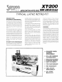
TYPICAL L.ATHE ,RE'TRO-FIT
SMALLEST IN SIZE,
BUT BIGGER IN PERFORMANCE.
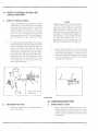
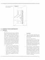
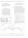
The Series XT-200 Linear Scale is the smallest
DRO scale on the market today. Being only
06" deep and OQr high. the XT Series is
approximately25% smaller than other similar
glass scales For the tirst time ever. it is not
necessary to pay thousands of dollars for a
DRO system that will fit in those minute
areas.
Space-age technology and micro-electro
nics have shrunk the scale. reader head.
and increased accuracy. reliability. per
formance and cost effectiveness. Metrilon
wear pads are permanently masked on the
optical encoders to automatically set an
accurate 1 mil air gap between the moving
and stationary components of the encoder.
Metrilon is a new technology which has
proven to be cost effective. improve perf
ormance. and reduce size of optical
encoders.
RELIABILITY WITH PERFORMANCE
New technology not only allowed the XT
Series to be the smallest glass scale on the
market. but it also promoted improvements
,-
l
in reliability. performance and reduced cost.
These improvements were realized by unit
inQ miniaturized ball-bearing rollers. metrilon
reticle pads. new solid state electronics and
inovative packaging
Incorporating metrilon encoder reticle pads
nos significantly reduced the air gap
degradation that has plagued other similar
type scoles. Conclusion of extensive tests
have depicted little or no pad wear after a
million inches of travel.
Using ball-bearing gUides has notedly
reduced wear as the encoder slides up and
down the glass scale. improved repeat
ability. and accuracy. and also reduced
hysteresis error.
Using the latest solid state electronics,
including long-life infrared ligilt sources, has
allowed only the optics to be incorporated
in the encoder Sub-miniature signal con
ditioning, analog to digital conversion and
amplification electronics have been
combined into the external interfacing
cable connector This feature hos reduced
encoder weight by more than 5()%,
therefore further reducing encoder wear
and hysteresis error.
Additional features of these exclusive
engineering achievements are: rninio
tu rized plug- in bipolar integrated elec
tronics packaged externally from the scale/
encoder makes repairs simple. reduces
packaging and environmental cost. and
furthermore increases slew rates up to 45
inches per second.
ACCURACY
The XT-200 Series accuracies are assured by
using vacuum deposited chrome on soda
lime glass scoles. Each chrome line Width is
held at on incredible tolerance of better
than 45-55'Yo of a cycle Accuracies of better
than 50 micro inches have been assured by
generating replication masters with ad
vanced numerically controlled laser inter
ferometer techniques that are traceable to
National Bureau of Standards. Environ
mental conditions have been stringently
controlled With seismic isolation facilities,
temperature uniformity of better thon 0.01'
Farenheit. humidity controls and automatic
barometric compensation to within 1 part in
10 million.
*
ENHANCED INSIDE·
DIAMHER
MEASUREMENT
to 50% INCREASE
* 30I N PRODUCTION
IN SCRAP
** REDUCTION
INCREASED PROFITS
EASY TO OPERATE
* TWO
YEAR WARRANTY
* NBS TRACEABILITY
* 100% ON· SITE
* SERVICEABILITY
*' 20% POWER
REGULAnO~~
TYPICAL S
to 12" CROSS TRAVEl. by 36" to £l0n
'n~AVEL
LONGITUDE
SYS1'EM INClUDINIG HARDWARE
Can be your's for as UUle 0$
$1195800
XT-230
XT-250
RESOLUTION
000025''O005mm)
0.0805' (OO1mm)
ACCURACY PER FOOT
250
I~
I,EPEATABILITY
300 /L inches
300
RECOMMENDED DISPLAY
700 Series
700 Series
SLEW-RATE
50"/Sec
50"/S8c
LIGHT SOURCE
SEI'lSING ELEMENT
.'-_.-
-----_._-----._----,-
-
-
-
_--
--.-._-----_ .. , -
---_.,..
~---,.-._----_.
-----,
E'lCODER OUTPUT SIGNAL
QUADRATURE SQUARE WAVES TIL OR CMOS COIVIPATABILITY
AMBle'lT TEMPERATUPE
DC TO 50°
-
Sorgon industries reser\'8S the
rlg:'1t to chorlge spociflcoJiom
designs, pnces, and models
Wlt'--Iout ,,,,,,o(ce.
- --- ---- - ---------------<==
- - - - ---"'-
inc hes
FOUR PHOTOTRANSISTORS (FIVE FOR ABSOLUTE OPTIO'lS)
--
c:::::Il~
is AVAILABLE
2" (50mm) TO 50" (1315mm)
- ----,----_._, .. - -
OPTIONAL
_
I'
FOUR INFRAI<ED L1GHT-EMITIING DIODES (FIVE FOI, ABSOLUTE OPTIO:'lS)
-------,----
SCALE LEf,GTHS
-
250 IL inches
inches
------_.',"-,._-,--
+ 10V ±
20% or 5V
±
at APPROXIMATELY 175ma
For more information
see your toea:
Sargon Dea!er
~
~--------
......
-=- -== ~ ----_
~ -::=:- = =
INDUSTRIES, INC.
----_._----
._--
- - _ . _ - _ ..
_ - _ . _ . _ - - - - - - - ..--_. __
'
940CJ Lurline Avenue, Cho1sworth, CA 91311 ,,(818) 701-0557
SARGON 2024/3/4·85
I~IDUSTRIES,
INC.
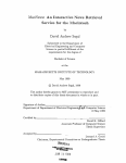
APPI.!ICATION NOill: 85tH
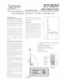
UNIVERSAL HEIGJ=IT GAGE RFTRO=FIT
SMi4U..ssr IN stzs,
BUY l8iGGHl iN
PERt'=O~MANeE.
The Series XT200 Linear Scale is the smoUest
DRO scaie on the market today. Being only
OF deep and oor high. the XT Series is
approxirnoleiy25'/o smallern'an other similar
gloss scoles For the first t;ni8 ever, ir is r.ot
necessary 1-::) pay thousands of oonors for a
DRO system that will fll in those minute
areas
Spao?-oge technoloov and micro-'21ectro
nics hove srrurik ~he scale, rc;od,ai head,
and increased or.curocv. ic,!i'.Jbii11V. per
to.monee and cost effecL'/eness. f\~e~r!,ion
v;eur [J'::.:ds ore De,rnOnE=;IIT;~/ r,---,osked en ~;':.-:
opt:coi encoders to our()n-:Ghco!i\ seT OJ'-I
occuroto "1 rTi;i 01'['JcP bet',VE:8" the mov:n;7
':-:i:d siatlano:y ccrnponenTs of tnG-) encoo-::::r
i\l1etri!cr: is 0 net) ~c~chr'J!c)g\/ whic:1 (·OS
prOVe!i to be cost etfeciivr=;'. l,nprGv\::_~ f.]8rf
ern-ionce, ':.In(j reduce size (if opt icc,'
encoders
encod,?r makes repairs sirnp.e. reduces
pockagir-g and er-viror.mer-tol cost. and
fur1hermore increases slew rates up to ~5
inches per second.
The XT-20J Sorres accuracies are ossu-eo o
using VOCUU'll deposited cnrorne on sc:,da
lime glass scoles Each chrome Irr,e '!/rdti-, is
held at an incredible tolera.nce of better
tho n 45-55% of a cvc:e J\ccurocies Dr better
thon 50 miCIO irlches have bee'-i ossurco 0\1
ger;e~jing repiicat:cn rliClsters \vilh oo
vonced numerical!y corurouoo loser :[lter
ferameter Tec~lfliques that ore troc'2:-Jbi8 tc
r'~ot:or,ol dGrt=..:ou of Stor.oruris tli'/!fGrl
rner.to: r:orlo;tiC)i!S .~Cive t)e8il S1r"L!~iQerd:,!
c:on~-rol!E,'U' \j,.'iih
isolotior'~ klCi!itir:~s
ternpeiOIUrf.j u~rif:')rrr(\, bl-?ne! :-he-'! c.
FOfr::;n~eit. rlun-!idiiy CC:"ltl :::;'!:3 orio clutc:'mot,c
oororiietric cGr~·lpE£lSUriCJr; to \vitnr:-\ . ~j..Jr;
1
l
/10 rr:!ili'_ln.
~~Eu,~murv wm~ r£RiFaRr.~ANCfE
New technology net oniy ':Jliowedihe XT
Series to be the srno'Iesi glass scale on the
market. out it also promoted irnorcverr-ents
in leliobili1y. performance and reduced cost
These improvements were realized by ur-r
ing rrur-io.urizeo ball-bearing rollers, rnetnlon
reticle pods. new solid state electronics and
ir-ovotive packaging.
Incorporating metrilon encoder reticle pads
has significantly reduced the air gop
degradation that has piagued other similar
type scales. Conclusion of extensive tests
have depicted li1ile or no pad wear atier 0
million inches of travel
Using ball-bearing gUides has notedly
reduced wear as the encoder slides up ono
down the glass scale. improved repeaT
ability, and occurccv. and also reduced
hysteresis error
Using the to tosr solid state electronics.
includi ng long-life infrared light sources. has
allowed only tile optics to be incorporated
In the encoder. Sub-minioture signal con
ditioning. analog to digital conversion and
amplification electronics have been
combined into the external interfaCing
cable connector. This feature has reduced
encoder weight !)y more than 50'10.
theretore further reducing encooe: wear
and hysteresis err)r.
Additional features of tr,ese exclusive
engineering achievements are' minia
turi 7 8 d plug-ir'. bipolar interJrated elec
tronics packoged externally from the scale/
AV~dlf~l2l~
~IEA1Ul~t2S
'* LOW PRICE
1< ABSOLUTE/INCREtViENTAL OPERATIOI\J
'* NOI\J-VOlATILE MEMORY
'* INCH/METRIC CONVERSION
* MACHINE ERPOR COMPENSATION
*' PRE SET
'* MADE IN USA
'* TWO YEAR WARRANTY
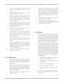
COMPARiSON
Aoproximafe1y
25 percent
smo.:e: to
(It those
rrunute ore os
Shoded area
Sorgon
lVIini Scaie
lS
5'
TERMS Ai\lD CONDITIONS OF SALE
The following terms and conditions shall be a part of any contract 0,1sale which may be entered Into between the Buyer and Seller. Any terms and conditions In Buyer's pUrC'13Se order acknowledp erne nt or
any ether writing pertaining Ie such order, irrespective of its wording or 01 when received by us, which ere in conflict or inconsistent with or add to the terms and conditions hereof, will not be acceptable or
become a pan ot any resulting contract without our express ly,ced or he ncwritten conse nt. Neither acknowle dqern en! and retur n ot a CODY cf Buyers pu rchas e order or ether form, irrespective of its terms. nor
the filling and shipmen: of such order, shall constitute acceptance of such contficllnq. inconsiat ent or a dditiona l terms nor s hai! l he yrn any W2Y cper ate :c rnodilvo r change the fuii effect of the terms and con
ditions herein
r.
4.
PRICE AND TERMS OF PAYMENT
a
Prices of prcducts are published seuaratety The acceptance of c-oe-s ISs utijec! to the appr ova: cf our Credit Department. Unless oth erwls e specu.canv agreed upon In writing, cur ter-ns are net 30
days from date of mvorce. All pavrnenls are to be made In USA funds
Prices are subject to chanpc without notice at any time prior to sbipment,
c
Export orders, unless otherwise specifically agreed upon in wri1ing shall be payable in USA funds.
d. Taxes Unless otherwise indicated r10Sales. Use. Hetailets. Occupation, Service Occt.p auon. Service Use cr other stmtta r taxes are included in our vices- The amount of any such taxes which ar e paid
or payable. or assessed, in connection with any order. and which shall be pa-d by the customcr tc us or, i:' authorized by law, by the customer directly to l he L:'OY.ing aotttority
CON FI RMfr-lG OR DERS: Seller shall hold Buyer responsible lor any order that is duplicated by Seller because Buyer tailed to mark the ord'~r"CONF!R MI NG ON LY" boldly en the' face of the order. Guyer
must indicate. on the face ot the wntten quotation from Seller, or the date and person at SI1RGON INDUSTRiES fNC. (0 ..... hom the order is confir rne d
DELIVERY: 1\11 s hipment s and prices are quoted FOB Origin. Title to all goods Sh211 P2SS to Buyer upon ccuvcrv (C) 8. common carrierorwhen Buyer takes possession of coeds at Se t'ers place of business.
Seller shall no! be liable lor delay in delivery orfor failure to pertorrn due to causes beyond U..-e rcasc nable control cf Sedler. These causes shell include, without iimif ation, acts of Gcd. act or orrussic ns of
Buve r, civ II or milit ary au thonti e s. delays in tra nsoorta -Io n, or ina brlity to obla in necessary Iabo.. m areriats or su ppues. lilt h 8 event of a ny delay. the c ont r actura' rta t e of delivery, If an y shall be extend ec tora
period e qualIo the rime lost as a conscqvance of such delay, without pe nalty to Selter cr any liability on Seller's p,--'
Seller shal! oeve the right to oetivcr a!t qoods covered h e rebv at cne time cr in PO;""..IOr.S
ftcm lime 10 time, within the time for delivery provided in such order.
CANC E LLATION: Orders accepted by Setter may be cancelled by Buyer only upon writ len consent of Seller. I"
any order, fa, any re-es cn and without limit
ing any other remedy which Seller may h8ve as 3 result 01 such cancetla tion or other withdrawal under the
Code 01
rea sen able cancetlation and/or restocking charges,
which sf-all inclUde all expenses then incurred anc comrnitrnents made by Seller, shall be paid by Buyer 10
CREDIT: In case Buyer sbatl fail to make pavrr.enl s On this or any other cor-t-act between Buyer and Seller in accordance wit', Seller's terms. Seller may deter future shipments un Iii suc h payments are
made, or may. at its opnc n cancel uashippc o balance. Seller reserves the right to refuse all orders deemed unacceptable b): rr~2S0,1 01terms of payment, Imanciat responsibility, or other sound bu smess
reasons. In addition 10 lh e prices stated herein. the Buyer expressly agrees to be liable for interest at the m aximurn allcwab!e contract rate under applicable 'aw on past due acoounts and for collection
cost, including attorney's fees, court and other costs involved in the collection of past due accounts, The Guyer expre ssf y agrees to be liable far any L,'."TE CHARG~ 2S may be permitted by Catdorn ia law.
The LATE CHARGi:. wili b(~ computed and applied 2: the :218 of 5% of each pas! due payment or at $5.00 rninimu'n cbar qc for E:ac~130 DAY PERIOD P!"ST DUE, whichever is qreater. Seller retains 2nd Buyer
hereby grants a security interc st 0,'1 the goods, inclucinq all acces s'ons to and replecernents of them until B<:";'r hGS mace payment in Iuli. Buyer s hal. cooperate f utf y with Seller in executing such
documents. inclucmc a Uniform Ccmrnerctal Code fmancmo stateme nt. and ac cornpllstunq such fillings a no/c r recorotnos ther eof as Seller may deem necessary for the crotecttno of such s ecunty
interests.
Payrne nt must be made from this invoice. No statements issued or customer supplie-d vouc he r forms completed.
$20.00 re-hilling charge on unearne-d discounts and/or deductions.
SHIPMENT
c...
Tf e time or c alivcrv named by us is the; date for shipping from Our ptant or ware house. We will no! be liable
deliver/caused by anvrca scn beyond our controimctudino but not limited 10 acts
of Gcd, casualty, civil disturbance. labor disputes, transpon ation or supply difficulties. any inle rrupt.on
or ac: of governmental authority and the time for delivery s peened her ern shall be
extended during the continuance of such co-idittons and lor a reasonable umc there aft er.
Make
b. Examine rnatc rial closely before maki-iq claim Ior shortaqe as this material was checked before shipping. 1\11 claims for defective merchandise m L.st be
claims lor breakage or damage in transit to co trier 2S we hoid shipping receipt In good order Claims for shortage orincor rect mate rialmust be
qooos and accompanied
by original pac kmq s he et. Male ria l returned lor credit subleot to a handling charge.
e. Unless otherwise agreed upon in writing, all shipments are f.o.b. au,' plants or warehouses from wruch material is shipped. We are .'101 responsible for damage 10 or loss of prc du ct s aue r dehvery to lhe
transportation company. If the customer s hould have a claim aqainst the l r ansport atlon company, however, \':e will cooperate in attempting to secure an adjuslmerlt when so rel),lJi?sted
d. We \..,,111 decid~ ho ..·.. to pack and to ship ur,less specific instructions arE: given
e. Where shipment from stock is inrkaled rn2lerial is subject to prior sale,
I.
All orders wi\l be shipped UPS If possibie and at the convenience c·f Sargon Ind. the Buyer may requesl an altem2.tf: shipping method and/or carrier; In so doing howeverSargon Ind acb On th8 cus'
lorners behalf without responsibility an Itself.
TRANS FER OF OWN E RSH I p: "The sellfH shall retain ownr!rship ot the products supplied until payment in full h2s been rec8ived by l1im. I\s the seiter retains ownership until Ihe producls are paid for. they
m2.y nol he sold and Sargon Ind. reserves product own8fship e',en when transferred by origninal customer to another pariY securing his claim against Ihe customer until lull payment is received."
PROPRI ETARY: N FORMATIO N: "SarC)on Ind. is the uwn8r and retains full title and copyright privileges on any suppLed design/application information which may be patentable. etc- e\.'en \..."henprovided
to a third pariy. f\ny and all papers regarding same arc to be returned upcn request ..
9. TRANSPORTATION CHARGES
a
Premium rale services such as Express (Rail or Air) /\ir-freigh~ etc. will be utilized only when speCified by customer. If prepayment is requested our invoice vlill shcv·.. 3n addition equaltc tl,e exc~SS
transporiaLlon charges.
b
Unless other>\lise requested in writing. Sjoods shipped by Parcel Post will be insured 2nd the postal fee pnd rnsurance charges ''iill be added to the invoice,
1 O. SELLER'S RIGHT TO INC R EASE PRICES: Seller r8~erves the right to increas~ the selling price of 2ny and all good::, orDered by Buyer but not shipped ;rOlll Se118r's place of business, pfior to ('In increase
in Seller's cost of SUCI; goods as reflected by 2 price increase to Se!ler from Seller's supplier. The selling price quoted herein shall, upon increase in v,c~ by Seller's supplier. be increased lJY ~ i)erc~ntage
equ21 tQ :h~ percentage of increase in Scller's cos: lor the 900ds. and Buyer agrees to pay any such increased ~'I'ice In accordanCe \vith the terms hereoi
Seller reserves the right to change price, specifications, and m8nufaeturer without notice.
11. PATENTS: Seller shall have nc 1,;atJilityof any kind with respect to any 2clu81 or ::o.lIeged infringement of <:iny 1.1 nited States or foreinn patent. trademark or Similar right
i 2. INSTALLATlON: Buyer shall be solely responsible for (he inst;)l!alion and operation of the goods covered herein, including wit houl1lmilalion, the obt2.ining 01all permils, licenses or ceriiflcates reqUired
for the installation or use 01such goods. All Sargan Industries Inc. linear encoder accuraciesarc directly traceable tothe United States National Bureau of StandardsVi2. Prlflla.ry and Secondary Standards.
I'v12.chl:le tool system posilioninc accuracies are dlreclly rela\c'd, lJut not lirnltec la, t'le cond:tion of the machines slides, W?iY, gibs. bearirgs, table defleclion.lead screw. orld l.'Iork plcce distance tram the
linear encod(;'r Therefor allY cos! thaI Sargon inherits Ihat is traceable tu machine 100i error. buyer's installation (;1 non'coillpiiance (0 slandnrd machine tool practices, shall be paid for by lhe
Buyer.
13 MIN IMUM ORDE R CHARGE: The rninlmum charge on any customer order will not be less th3.n $1 00.00
14. 1\ ::olandard cha,ge cf $<1.00 per invoice or $2.00 per box, whichever is the greatest will be added to each invo:ce to cover the cost 01 pac~~aging maLe rial. Cos: ot Special bOXing, expcrt bOXing, carl2.0e 10
steamer or lraw'it or e>:penses will b::: added 10 invoices.
15. DESIGNS, DIMENSIONS AND WEIGHTS: Because we are constanLy impro'/ing our products, the designs, dimens\or,s. 2.nd ',,/eights shown In c'lIr cataloQs, while sufficienlly accurale tor most pur·
poses. are subject 10 variaJion, II extreme accur2cy is required, addllion2.! Iflforma1ion and certificaric;l .vill be providec; upon reques1 oller receipt of order
16. GISPUTES: 1\11 disputes under 3nycolltracl coo,cernlng the goods not othenvise resolvqcJ between Seller and Guyer shall be resclved in a court cf
lhe Seller's
17
12.
19,
20.
21.
pl;ice 01business a"d in no other place. pro'.-ided. howeverthal in Seller's sole c'iscrelion, such actio~ mOlYbe heard in some other pl2ce deslgna!ed b~:~~II~r(~'~::t~~~,Sr~~~r~)I~;;i~:~~~~~i~~'"i;i~'~~'~::~~,I<~:;~
r.:erson::;). so that the dispute C2n be resolved in one Olction. Buyer agrees to appear in any such action and hereby consonts to the jurisdiction orsuch court
out oj. or in
0.:1Y way connecled wilh the ~}Oods furnished or se,vices rendered by Seller, !~'lay be brought by Buyer rnore th2n one (I) year alter II"\e Gate of sale.
GOVERNING LAW: This agrGement and periormanu~ by lhp. hereunder shall be governed by the uniform Cornmercial Code of lhe St:::.ie of Californlc'L
RETURN OF EQUIPMENT: No material wil! be acc~pted f'Jr return for credit after90 days ;\11returns must h<:lvea return aUlhoriv.tion number and include the origina! invOice orpacKi"g slip number.
Return due to cuslomer's error must be returned prcpa'd and wlil be %biect to a S50.00 adminlstraticn fee plus a , 0% restocking charge
QUOTATIO NS: All Quutatlons will have a validity of 30 d2YS
WARRANTY:
a
Sargun's Digital Readout products and specifications arc warranted 2.gainst defective malerials and wori~manship for two years from da.:e of pUichc~e
b. T'lis warranty covers all parts except forcor:sumabie items_ This wa rr2nlyapp,lies only to ORO Systems and accessories that have been installed ara oDera1ed in accordance with Sargon's<;jl,idellnes,
Instructions and rEcognized reference publications. This '''/arranty:s void ....
· hen the syslerr.s are misused, da.maged or exposed to hostile environment, such as bul not limited to electrical or clec'
lcmagnetic noise.
Two Year Parts Warranty: Within tWo years from date of purch2se, all ',','arranted paris will be rc:placed or repaired '....i thout charge except jar l2lbor, frejpht and forwardi'1Q :ees fo cind frorn pOint of
repair. Sa.rgon Ind. is notliablf! tor ar.y design engineere:d and/or furnished by the Buyer and i'1corporaled into equipment.
d. One Year\Varranty: If within one year from the uateof purchase any ::iuch defect is lound, the part or parts, wil! be replaced Or repaired ....-ithout charge except for inilenterj freight 2nd iom'arding fees
from pOint of repair
c. Disclaimer of Implied v/arranties: The foregoing v"arranties o( Sargon Industries are in lieu of all other v..arranties, expressed cr implied.
Sargon Industries specifically disclaims any imp!'e::: WClrranties or merchant;:Jbillly or fitness lor 2. part!cular purpose. In no cyen! will Sargon Industries be liable fer ::;peciiJ.1 or conseq uerliial damc.ge.
ir.cluding any producl which has been cperaled in excess 0: its ek:clrical. m8cb~nical, or environmental rating, or which has beer~ ::il..ibiect to abuse, or in which (he housi"lg nas boer, altered or tam
pered with,
CHAN GES: If a quotation p,'cvides for produc~~ to bl"! r::ustom made lor speclalappllc2lions, the quoled price is ::'!Dr1ieahle only where correct iolerance requirements are prOVided by the customer by rrint
or sample pJri. We have the right 10 terrninate such orders without obiigatlon to either pariy if, In our opinion, it IS no! possible to meet the required specifications. if chenges in fabrication o' design 2re
required by reason or incorrect tolera.nces furnished or deViation from prints or samples submitted the cost of such changes shall be at Ihe customer's expense and shall be added to the quoted
price
22 CANCELLATION: Suspension or cancellOltion of crders may t:e made upon our
wrlt~en
approval and on terms that
w~lllnd('mrlify L.S
aga:ns: all loss
23. ORDER ACCEPTANCE: Orders sh'lll not be deemed accepted until appro'/ed in writing at cur plant Se!ier reser,res the right to refuse any order
2·1. GENERAL;
a
These terms and conditions zre subjecllo change ..' ",thout notIce.
b. Unless olhernise ~t~ted, a Q'e-:otalion IS valid only for a period of 30 days frorn date of the qU0tation.
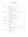
CONTENTS
PAGE
SECTION I
SECTION II
SECTION III
SECTION IV
SECTION V
SECTION VI
100 Series Scale Assembly Installation Procedures...............
1
A
Introduction
1
B.
Pre-installation
1
C.
Spar Alignment Tolerances
D.
Longitudinal Travel Installation
E.
Cross Travel Installation. ... ... .
'"
2
'" .
..
.
2
.. . .
5
XT200 Series M iniscale Assembly Installation Procedures. . . . . . . ..
7
A
Introduction
7
B.
Pre-installation
8
C.
Scale Alignment Tolerances..................................
8
D.
Longitudinal Travel Installation
9
E.
Cross Travel Installation
10
Display Installation and Cable Routing
13
A.
Display Installation
13
B.
Scale Assembly Cable Routing to Display
13
Performance Test.
13
A.
Operational Test
13
B.
Repeatability Test.
14
C.
Accuracy Test.
14
Eq uipment Installation Variation
15
A
General
B.
Lathe
C.
Grinder
15
D.
Vertical Milling Machine Quill Mounting Procedures
15
E.
Knee Mounting Procedures
15
F.
Custom Fabrication
15
Preventive Mai ntenance
17
A
Cleaning
1.
Display
2.
Scale
15
,
15
" '"
17
17
" 18
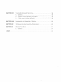
SECTION VII
Trou ble Shooting and Servicing
18
A
General
18
B.
System Trouble Shooting Procedure
C.
Linear Scale Trouble Shooting
,
" 19
19
SECTION VIII
Disassembly and Assembly of Display
SECTION IX
100 Series Encoder Assembly Replacement
,
20
SECTION X
Machine Tool Error
"
21
A
General
"
"
20
,
21
INDEX
"
r J .~
23
1m
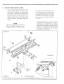
100 SERIES SCALE ASSEMBLY
6NSTAlLATION PROCEDURES
A.
INn~ODUCTION:
The following instructions are guidelines for in
stallation of SARGON'S 100 Series spar, glass
scale and encoder assembly.
NOTE
This manual describes installation
procedures for Bridgeport type knee
mills. All part numbers are located on
individual hardware kit drawings lo
cated in each hardware kit. To order
replacement or additional parts, use
the kit part number and machine
manufacturer reference, as some di
mensions and parts may vary bet
ween manufacturers.
NOTE
Other machine types may require spe
cial hardware fabrication. The actual
scale installation in all cases, follows
the same concepts, custom installa
tions may be completed without
assistance; however, factory assis
tance is available if necessary.
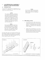
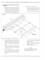
The spar, glass scale, and encoder assembly have
been factory aligned and shipped as a complete
unit. Twotemporary#4-40screwsand metal stand
offs, Fig. 1 B Index 1 & 2, hold the encoder "fin" in its
proper aligned position to the spar.
NOTE
Do not remove the temporary/align
ment screws until the assembly is
bolted in place and the installation
is completed.
B.
IPFUE·H\iSTAlltllTION:
1.
Installation of spar, glass scale and en
coder assembly on most vertical milling
machines is relatively easy and straight
forward. STAI\J DARD MACH 11\1 E SHOP
PRACTICES SHOULD BE EXERCISED
AT ALL TIMES.
2.
Other types of installations may require
different mounting hardware, but at all
times the installer must maintain the speci
fied spar alignment tolerances to achieve
optimal performance and accuracy.
FIGURE 1 B
FIGURE 1A
. -!---:- ~
1-v-_~2
'---_ _1----------+-----7
Scale Assembly
I...-_~~~-----------
Encoder temporary alignment sub-assembly
. Sri
* .;
C.
-'~.-
~
,
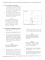
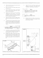
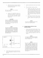
2.
Using a depth micrometerordial indicator.
indicate the glass scale face surface to
parallel the table travel within ±:O.005
inch. Deviations can be corrected by
inserting shim stock between the spar
and table surface. See Figure 2.
liE
.' M
&&.@: ±&?4HS!
S
I
FiGURE 2
Align the glass scale top surface to paral
lel the table travel within ±O.005 inch.
This alignment can be accurately accom
plished by using a depth micrometer or
dial indicator. See Figu re 2.
NOTE
After installation is completed, it is
recommended to recheck ali align
ment tolerances prior to removing the
"fin" screws and stand-offs, inspect
for any movement in the encoder
assembly. Any encoder movement
will require re-alignment.
Glass scale alignment procedure
lONGITUDINAL TRAVlElINSTALlATION:
1.
Position the table in the middle of it's
travel (halfway).
2.
Remove the mechanical stops from the T
slot in the front of the machine tool table.
3.
Remove the table stop bracket on the
front of the saddle and mount the reader
head bracket, Fig. 4A Index 3, usi ng two
bolts, Fig. 4A Index 1, and two washers,
Fig. 4A Index 2. The bracket should be
mounted as high as possible without
rubbing against the table. Bracket may
need to be milled or angle changed, for
some machines.
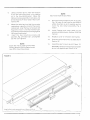
table and tighten, making sure that the
encoder casting box is at the same height
as its mounting bracket. See Figure 4C.
NOTE
For some machines the encoder
mounting bracket is off-center. To
accomodate this, the scale should be
adjusted that same amount to the side
of the off-set.
NOTE
Be sure that the scale does not effect
the table lock If this occurs a table
lock extension is available for your
machine. Fig. 4A Index 8 & 9.
NOTE
For Lagun mills and mills that do not
have a tapered angle to the front of
the saddle, refer to Figure 4B.
4.
Reference Figure 1A, remove the end
caps, gaskets and cover from the scale.
5.
Utilizing the T-slot in the front of the table,
mount the scale to that surface as per
Figure 3. Be sure that the top of the scale
assem bly does not sit above t he top of the
- "1--'""
2
s.. -&
SPAR AUGNMENT TOlIERAi\'lCIES:
1.
D.
'+?U;;;+
- 9
6& *W"~+*,-
6.
Align spar as per procedure depicted in
above Paragraph C(SCALEALlG~IMENT
TOLERANCES).
7.
Encoder casting box should now be direct
ly in front of its mounting bracket. Remove
the cover from the encoder casting box.
See Figure 4A Index 4 & 5.
6E
-~+
5"'
.
fd%s if/b··S' ·hi'
SF
E
8.
Using a transfer punch, mark the location
of the two mounting holes in the casting
on to the mounting bracket. Move the
table and scale assembly to one side. and
drill and tap two #10-32 holes in the mount
ing bracket.
9.
10.
Move the table back so that the encoder
casting box is directly in front of the mount
ing bracket. Align the four set screws, see
Figure 4C Index 1, into the encoder cast
ing until the set screws are just snug against
the mounting bracket.
Insert the two mounting screws and
washers, Fig. 4A Index 6 & 7, and tighten
(do not over-tighten).
NOTE
Each axis has a green ground wire
locking terminal that is placed under
one of the mounting screws.
!ii£Sio"
NOTE
Each axis must be grounded.
11.
Remove the two temporary #4-40 screws,
Fig. 1 f3 Index 2, and traverse the table to
either direction so as to expose and re
move the two metal stand-offs, Fig. 2
Index 1.
12.
Install Display and route cable as per
procedure described in Section III of this
manual.
13.
Replace cover on encoder casting box.
14.
Execute performance test as depicted in
Section IV.
15.
Assemble spar's cover as per Figure 1 A.
WARNINGI Ensurewires going to encoder
do not rub against spar cover or fin.
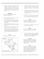
FIGURE 3
<,
>
Longit/ldinal scale assembly mounting procedure
3
Q
641&5
5?&
;
.
-
k
2
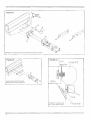
FIGURE4A
/~
-r:
"(z)
3
,
, encoder mounting procedure
Bridgeport longitudinal
exis
FIGURE4C
scale 100
'~
axis
Lagun type IOn iiuolnet
procedur~
encoder moun t7ng_
~
1
~~
table
bolt
Bridgeport l.onq!'tucinet
, f
exts' cross sect/on Vleill
4
~
I
V-bracket
E.
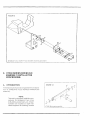
CROSS TRAVEL INSTAllATION
1.
Select preferred side of the saddle, Posi
tion the cross travel at the center of its
travel and lock saddle. Review Figures
5A, 5B and 6. Locate the mounting position.
Mount back plate, Figure 5A Index 7 or
Figure 6 Index 1, to the knee via two
spacers, Figure6lndex2, with the screws,
Figure 6 Index 3, or washers, Figure 5A
Index 1.
drill and/or re-tap the threads to the
size required for your machine (see
your hardware parts list for bolt size).
On some machines there are no holes
pre-drilled. If this is the case utilize
the universal backing bar, see Figure
5A Index 7,
2.
NOTE
For some machines the holes are
either not drilled, untapped, or are
clogged with paint. If this is the case,
FIGURE 5A
Align back plate as per paragraph C (SPAR
ALIGNMENT TOLERANCES), If the uni
versal type back plate is being installed,
adjust the four (4) jack screws to align the
parallel axis. WARNINGI DO NOTWARP
OR TWIST THE BACK PLATE BY JACK
SCREW MISALlGt\IMEt\IT.
[ , <,
I
I
1~
2
I
~
3
7
FIGURE 58
100
8
FIGURE 5C
10
16
Universal cross-travel
mounting procedure
5
.±is :,:
'* £ii
sei·;;:'&h· 04
3.
Remove the end caps and cover from the
scale. See Figure 1 A.
4.
Mount the spar to the back plate as per
Figure 5A or 6.
5.
Align (indicate) the scale to the travel
(ways) using standard alignment proce
dures, see Paragraph C.
6.
Remove the cover from the encoder
casting box, Fig. 8 index 1, 2 & 3, and
temporarily bolt the encoder mounting
bracket, Fig. 8 Index 4, to it usi ng two each
#10-32 screws and washers.
7.
Adjust the table so that the saddle aligns
with the encoder bracket, Fig. 8 Index 1,4
& 7.
8.
Transfer the holes located on the encoder
bracket onto the saddle. Move the saddle
to allow room for drilling Drill and tap two
V4-20 x 1" deep holes where marked, Fig. 8
Index 7.
9.
Unbolt the encoder bracket and mount it
to the machine, using the two V4-20 bolts
and washers, Fig. 8 Index 4,5,6 &7.
10.
Readjust the saddle so that the encoder
bracket holes line up with the holes in the
encoder casting box. Adjust the four set
screws, Fig. 7 Index 1, until the set screws
are just snug against the mounting brac
ket.
11.
+a
Insert the two mounting screws and
washers, and tighten. DO NOT OVER
TIGHTEI\J. See Figure 8 Index 8 & 9.
a green ground wire
%'f{)9J$ing,terminal thatis placed under
12.
Review Figure 5A Index 8, 9 & 10 for an
installation concept of Universal cross
axis encoder bracket.
FIGURE 7
fur sOl1le types
of back plates
2'
I"rf~:,±,----
------
X4)
FIGURE 6
4
5
5
Bridgeport Tvp e cross-travel mounting procedure
f
6
Universal cross-travel
~
IT
ff&hl~f
mounting cross section
q;
r------~-------------------~--~-~---
FIGURE 8
Bridgeport cross travel (Y Axis) encoder mounting procedure
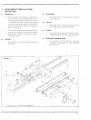
II. XT200 SERIES MU\USCAlE
ASSEMBLY INSTALLATION
PROCEDURES:
A.
INTRODUCTION:
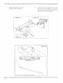
FIGURE 14
The following instructions are guidelines for installa
tion of SARGON'S XT200 SERIES rvI11\lISCALES
assernbly.
NOTE
This section describes installation pro
cedures for Bridgeport-type knee
mills, lathes and grinders, etc. All part
numbers are located on each indi
vidual hardware kit drawing, located
4
XT200 Miniscale assembly
;g
7
EM··
--9£ &
C.
in each hardware kit. To order replace
ment or additional parts, use the kit
part number and machine manufac
turer reference, as some dimensions
and parts may vary between manufac
t u rers.
NOTE
Other machine types may require spe
cial hardware fabrication. The actual
scaie installation follows the same
concepts. Custom installations may
be completed without assistance;
however, factory assistance is avail
able if necessary.
The alignment bracket (transportation bracket)
assembly, Fig. 1 Index 2 and 3, keeps the encoder in
its pre-aligned calibrated state.
1.
Using a micrometer or dial indicator, indi
cate scale housing surface to parallel the
table travel within ±O.005 inch. Devia
tions can be corrected by inserting shim
stock between the scale housing and
table surface. See Figure 15 Dial Indi
cator.
2.
Align the scale housing top surface to
parallel the table top within ±O.005 inch.
This alignment can be accurately accom
plished by using a depth micrometer or
dial indicator. See Figure 15 Dial Indi
cator.
NOTE
After installation is completed, it is
recommended to recheck all align
ment tolerances prior to removing the
alignment bracket. I nspect for any
movement in the encoder assembly.
Any encoder movement will require
re-alignment.
FIGURE 15
PRE-INSTALLATION:
Installation of the miniscale and encoder assembly
on most vertical milling machines, lathes and grinders
etc., is relatively easy and straight forward. STAI\J
DARD MACHINE SHOP PRACTICES SHOULD BE
EXERCISED AT ALL TIMES.
I
~
\
Other types of installations may require different
mounting hardware, but at all times the installer
must maintain the specified scale housing align
ment tolerances to achieve optimal performance
and accu racies.
@
XT200 Series housing alignment procedure
8
:•.,;sB
SCALE AliGNME/II:lT TOLERANCES:
NOTE
The bracket should not be removed
until installation is completed.
B.
&
- i3
D.
E51i
'4
LONGITUDiNAL TRAVEL INSTALLATiON:
(X AXIS)
1.
5&3&:
?F
5.
Mounting and Alignment of Miniscale
Housing. It is recommended to mount the
longitudinal scale on the backof the table
and mount the encoderto the saddle. Full
scale protection can be realized by using
Sargon Industries specially designed
515-C Guard cover. See Figure 16.
,iMi"
Mounting of Encoder Assembly:
a.
Review gap between encoder as
sembly and saddle and ensure that it
is 0.200 inch or smaller between the
encoder and machine surface.
b.
Transfer the two holes, Fig. 16 Index
FIGURE 16
~Front
8
o
I
Longitudinal scale assembly mounting procedure
2.
3.
4.
Position the longitudinal table at center of
its full travel and lock it. Position the scale
assembly against the rear of the table so
that the bottom longitudinal edge of the
scale is flush with the lower edge of the
table.
Transfer the two 0.3" mounting holes to
the table. Drill and tap for%-20 5/8" bolts
and mount scale assembly as per Figure
16Index2,5&6.
Using a depth micrometer, or indicator,
indicate the scale housing by adjusting
the two scale ends horizontal to each
other within 0.005 inch or better, See
Figure15.
\Scale
8
-:
7
c.
4, to the machine surface and drill
and tap for two #4-40 x 3/4 Socket
head cap screws.
Adjust the four jack screws, Fig. 17
Index 1, until they just touch the
mounting surface.
(DO NOT TIGHTEN TH EM.)
NOTE
Misadjustment can force the encoder
out of its calibrated position and create
erratic scale performance.
'.".'.-~
9
%
d.
? B
&.0
Reference Figure 16 Index 9. Mount
the encoder with two 4-40 x 3/4 soc
ket head cap screws.
7.
Execute performance test as per Section
V.
8.
SCALE COVER INSTALLATION:
a.
Position the guard over the scale
case ensuring that the guard is rest
ing on the top surface of the scale
case. The guard ends should fit bet
ween the scales two bushings and flat
against the scale case. The encoder
cable should be tucked inside the
guard.
b.
As per Figure 6 Index 3 and 8, locate,
drill and tap for four each 8-32
screws. Mount cover as per Figure
3.
NOTE
Do not over-tighten the encoder
mounting screws.
e.
Remove the alignment bracket as
sembly (Fig 14 Index 1,2 and 3), and
store the bracket assembly in a safe
place for future use and/or system
realignment.
CAUTION
Move the longitudinal table to its two
extreme positions while monitoring
the encoder travel. Ensure that the
table travel is not longer than the
encoder travel.
NOTE
If the encoder travel exceeds approxi
mately V4 inch from the scale mounting
bushing scale and/or encoder will be
permanently damaged. If machine
travel is greater than encoder travel,
table stop must be incorporated to
limit table travel.
reader head
set s c r ews
x4
XT200 Series
Cross Section
10
lEo
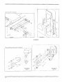
CROSiS TRA.\n~lIN§TAlLATION
INSTRUCTIONS
1.
Select preferred side of the saddle. Posi
tion the cross travel at the center of its
travel and lock saddle. Review Figure 18
or 19. Locate the mounting position.
Mount scale back plate, Fig. 18 or 19
Index 11.
NOTE
The style of the mounting brackets
are determined by type of machine
and/or hardware kit.
FIGURE 17
6.
NOTE
Ensure"O" ring gasket is fitted in the
guard cover's gasket groove.
Install display and route cable as per pro
cedures described in Section III of this
manual.
NOTE
On some machines the holes are
either not drilled, untapped, or are
clogged with paint. If this is the case
drill and/or re-tap the threads to the
size required by your machine (see
your hardware parts list for bolt size).
On some machines there are no holes
pre-drilled. If this is the case utilize
the universal backing bar, see Figure
19A Index 11.
..
2.
Align the backplate to the cross travel
(saddle) via standard alignment pro
cedures, see Figure 15 Para. C (Scale
Alignment Procedures). If the Universal
type backplate is being installed, adjust
the four (4) jack screws to align the paral
lel axis.
WARNING
Do not warp or twist the backplate by
jack screw misalignment.
3.
Mount the scale assembly to the back
plate as per Figure 1B or 19.
4.
Align (indicate) the scale housing to the
travel (ways) using standard alignment
procedures, see Para. C (Scale Alignment
Proced u re).
5.
Reference Figure 1B Index 3 & 7, tem
porarily bolt the encoder to Y axis encoder
bracket.
6.
Adjust the table so that the saddle is in the
center of the Y axis encoder bracket.
7.
Transfer the holes in the encoder bracket
onto the sadd Ie. Readjust t he axis to allow
room for drilling. 0 rill and tap two %-20 x 1
inch deep holes where marked, Fig. '17 &
1B.
dE
B.
Unbolt the encoder bracket from the
encoder and the encoder bracket to the
machine, using the two each 114-20 bolts
and washers, see Figure 1B Index 2 and
6.
9.
Readjust the saddle so that the encoder
bracket holes line up with the two #4-40
screw holes in the s'lcoder casting box.
See Figure 1Bind' .,
10.
Adjust the four (4) jack screws, Fig. 17
Index 1 until they just touch the saddle
surface (DO NOT TIGHTEN TH EM).
NOTE
Misadjustment can force the encoder
out of its calibrated position and
create erratic scale performance.
11.
FIGURE 18
Scddl ..
Bridgeport Cross Travel
(Y Axis) Mounting Procedure
Mount the encoder with two #4-40 x 3/4
socket head cap screws.
NOTE
Do not over-tighten the encoder
mounting screws. See Figure 181 ndex
7.
12.
NOTE
Bridgeport machines are pre-drilled.
5S
Remove the alignment bracket assembly
(Figure 14 Index 1,2 and 3), and store the
bracket assembly in a safe place forfutu re
use and/or system realignment.
CAUTION
Move the Cross-travel table to its two
extreme positions while monitoring
the encoder travel. Ensure that the
table travel is not longer than the
encoder travel.
NOTE
If the encoder travel exceeds approx
imately % inch from the scale block
bushing, the scale and/or reader head
will be permanently damaged. If
machine travel is greater than en
coder travel, table stop must be incor
porated to limit table travel.
11
13.
ENCODER CABLE ROUTING:
See SECTION III PARA. B.
FIGURE 19A
14.
Install connector as described in the dis
play section of this manual. Turn on dis
play and perform performance test as
prescribed in Section IV Para. A.
FIGURE 19B
11
FIGURE 19C
FIGURE 19D
Universal Cross Travel Mounting Procedure
12
o
FA
rn,
rHSPlAV SNSTJU.,lATBON AND
CA.BlE ROUTU\IlG
A.
iJiSPlAV INSTALLATION:
1.
NOTE
Figure 20 depicts a typical Sargon display
installation. The first step is to remove the
large eye bolt located on top of the milling
machine column, Fig. 20 Index 1, and mount
the arm (Index 2), as per Fig. 20. The next
step is to bolt the display to the display
mounting arm with a5/16-18 boltfound in
the Hardware Kit. See Figure 20 Index
Cable can be fixed to exit either right
or left of the encoder box. Ensure
sufficient cable loops to allow the
table to move to both left and right
extremes without exerting tension on
the cable, The cable slack should not
lie on the floor, or in a situation where
it could get pinched, cut or con taminated by toxic chemicals. All
damaged cables MUST be replaced.
4.
2.
The display can be mounted to the bottom
of the mounting arm by removing the screws
from the top sides of the display case ex
trusion and then removing the top and
bottom half of the case extrusion. Mount
the bottom case half on the top side of dis
play. Mount the top half of the case extru
sion tothe bottom half of the display After
completion, the top half should now have
a mounting hole in its center which you
use to bolt to the arm.
2.
Each cable connector is terminated into
its appropriate mating connector located
on the back of the display. Example: X axis
scale cable assembly connector will mate
with the connector called "X-I N" located
on back of the display,
1
/
c'"
2
4
Display mounting
procedure
FIGURE 20
IV. PERFORMA.NCE TEST
e.
ENCODER ROUTiNG:
1.
Route the cable from the encoder assem
bly to the display.
fuBitB&W~
A.
OPERATiONAL TEST:
1.
"'"
Plug in the display power cord to the A.c.
Power and turn on the Display power. The
Display ON/OF-F power switch is located
on the upper right hand side of the display
back panel.
13
'E
2.
ZERO the display by pushing the ZERO
button. The display should now read
"ZERO".
3.
Adjust the machine tool lead screw dial
clockwise to read "ZERO".
4.
With both machines and display on a
ZERO reference, crank the table and note
if the display is counting. If not consult
Section XI (Trouble Shooting Chart Sec
tion) for guidance.
5.
Measure a given travel and compare the
lead screw dial to the display. They should
be relatively close. If not consult the trou
ble shooting Section.
6.
Tighten the knee and table lock so the
table and knee cannot move.
7.
Turn the machine tool power on and off
several times. The display should NOT
add any new numbers to its count. If it
does, check the machine and display
grounding system.
8.
Check and/or adjust the mac hine tools
ways, gibs, and lead screw for good con
dition.
9.
Ensure that a #20 ground wire is connec
ted from the "GND" terminal located on
the Display back panel to the "MAINS"
earth, ground, such as the conduit for
"AS." buildinq power.
1 O.
B.
4.
Move the machine tool table to its other
extreme then bring the table back just past
the indicator zero position. Forward the
table to read zero on the Dial Indicator.
Both the Dial Indicator and ORO display
should now read zero plus or minus one
count.
5.
Perform step 4 at least three (3) times to
ensure good repeatability.
6.
If repeatability is not realized as per above,
consult the trouble shooting Section on
repeatability for guidance.
ACCURACY:
1.
Accuracy test procedures will only verify
the machine tool, and ORO installation
accu racy. The Sargon glass scale accura
cies are at least one thousand times more
accurate than most machine tools. Sar
gon glass scales are traceable to the
National Bureau of Standards (N.B.S.).
2.
To check accuracy, place reference stan
dard such as certified gage block and/or
indicator on the working surface of the
table. SimUltaneously compare the ORO
and reference standard accuracies to each
other. Repeat the measurements at least
three times. If there is a major discrepancy
between the two measurements, recheck
the scale installation. Generally speak
ing, accuracy deviation is contributed to
the following:
Proceed to the REPEATABILITY and AC
CURACY Test below:
REPEATABILITY:
1.
2.
3.
14
C.
Repeatability is verified by this test; Machine
tool and Digital Readout performance
should be periodically checked by this
procedure:
Mount a dial indicator on the machine tool
table in such a manner that the indicator
probe tip touches the scale assembly's
black end plate when the table is at one of
its positions limits.
Set dial indicator and the Digital Readout
display to zero.
.
3.
a.
Machine tool working area distance
from scale. (Abby error)
b.
Adjustment of machine tool "ways"
and "gibs."
c.
Machine tool basic accuracy.
d.
Scale encoder installation.
e.
Scale assembly mechanical align
ment.
For a better understanding of accuracy
review Section X (Machine Tool Error) of
this manual.
v.
EQlU PMIENT
VAfUATIOINJ
A.
GEi"IiEIRAL:
1.
2.
B.
~NSTAllATiON
C.
The enclosed mounting procedures for
both 100 Series and XT200 Series can be
adopted to other types of mach i ne tools. It
is important that the installer uses good
machine shop practices and follows the
general concepts of all procedures depic
ted in this manual.
The installer should be prepared to modify
and/or manufacturer various hardware
assemblies. Typical mounting lay-outs are
portrayed below:
1.
1.
D.
E.
See Figure 23 for typical vertical Milling
machine quill mounting assembly.
KNEE:
1.
See Figure 24 for typical vertical! horizontal
milling machine knee mounting assembly.
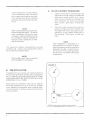
CUSTOM FABRICATION:
1.
See Figure 21 for typical lathe mounting
assembly.
See Figure 22 for typical grinder mount
ing assembly.
QUilL:
1.
F.
LATHE:
GRINDER:
The installer can fabricate the required
hardware assemblies by understanding
this manuai.
FIGURE 21
lDo0808c4 DHWUl
Typical lathe installation
r
*%
*¥
5*-;-8ȣ-
£
=
15
ruR &i
'Sb&ibh
5
&
Typical grinder
.
inst aII alton
.
..--
/
FRONT
_ _---!:!LD~O())\l\l:22 84<>G'
FIGURE 22
Typical
----=.-m,~a ch I.ne qUill
. 'Installation
_ _ _milling
/
~
I
/IO~~/ ~() 1/
~/ -"~TJ
/
/-\.":J..'
6'".'
16
*
oY'
FIGURE 23
Type A
*
FIGURE 23
Type B
55
Typical milling machine
&F±&
S&
-,
&"
"M
FIGURE 24
knee installation
VU. PiRlEVENTA"nVIE MAINTENANCE
A.
ClEANBMG:
1.
DISPLAY:
Dirt on components acts as an insulating
blanket and prevents efficient heat dis
sipation. It also provides an electrical con
duction path that can result in instrument
failure. The recommended way to clean
the interior is to blow off the accumulated
dust with dry, low pressure air (approx
imately nine pounds per square inch). Re
move any dirt that remains with a soft brush
or acloth dampened with a mild detergent
and water solution. A cotton-tipped appli
cator is usefu I for cleani ng narrow spaces,
or for cleaning circuit boards. Then blow
dry the dampened area.
a.
Exterior areas may be cleaned with a
soft cotton cloth, small paint brush,
or soft tissue paper. The paint brush
is particularly useful for dislodging
dirt on, and around, the front-panel
controls. Dirt that remains can be
removed with a soft cloth or brush
dampened in a mild detergent and
water solution or isopropyl alcohol.
NEVER USE ABRASIVE OR SOL
VENTS.
CAUTION:
b.
The counter display LED filter may
easily be scratched when using the
above cleaning procedures with dry
lense tissue.
Recommended method is:
Gently wash the filter with a soft clean
damp cotton cloth and clean water,
blow dry with low-pressure dry air.
Greasy residues or dirt may be re
moved with a solution of warm water
and a neutral pH liquid detergent, rub
gently with a soft cotton cloth.
c.
After cleaning, a visual inspection
should be performed to find such de
fects as broken connectors, heat
damaged and/or loose electronic parts,
and loose/broken wires. Overheat
ing parts usually indicates other pro
blems or potential trouble in the
electronics; therefore, it is recom
mended to contact the local service
center, or the factory.
17
2
a.
SHOOTH\~G AND
~ER\fICING
VUe TROUBLE
SCALE:
There is no preventive maintenance
required for the electronic and opti
cal circuits within the scale encoder
In everyone to three years, dust, dirt,
cutting fluid, ;:>.:lC loose chipping could
present a problem. Cleaning pro
cedures are the same as section 1 a.
above.
b.
100 Series glass scales and reticle
should be cleaned with isopropyl al
cohol and dried with a clean cloth or
paper towel. Special care should be
taken to follow the disassembly and
assembly procedures as depicted in
the scale installation section. Make
sure the scale assembly is secured
tightly and aligned properly.
c.
Cleaning procedure for the XT200
Series miniscale is as follows:
1.
Position table so encoder is at
one extreme location on the
scale housing.
2.
Using no more than 20 PSI of air,
gently insert the air nozzle through
the rubber flaps entrance of the
scale housi ng and blow air away
from the encoder towards other
end of the scale.
3.
Apply the air pressure in such a
manner that dirt and particles
will migrate to the other end of
the glass scale and fallout
4.
Move the encoder to the oppo
site end of the scale and apply
air pressure as per above instruc
tions.
5.
Using a spray dispenser spray
and saturate the glass scale with
alcohol.
A,
GENERAL:
1.
The following information is provided to
facilitate system trouble shooting pro
cedures and aid the user in communicating
problems to the local service center or fac
tory. It is not necessary to understand the
circuit operation to find the sub-assembly
that is at fault The factory has individually
set up and tested the overall performance
before each system is packaged and
shipped. In general the system will serve
the user without any operating difficulty,
and operate to full satisfaction when the
system is properly installed and cared
for.
2.
In the event of an operating difficulty or
problem refer to the below appropriate
trouble-shooting information guide and
see if t he problem can be corrected; if not,
contact the local Dealer/Service Center,
or factory for advice. Depending on the
nature of the problem, it may be necessary
to ship one of the sub-assemblies or units
back to the Dealer orfactory. The Cou nter
mother board or power su pply replace
ment is easy when instructions are fol
lowed.
NOTE
Do not ship any package to the dealer
or factory without prior notification
and approval. In such a case, pac
kage the components and furnish
information as follows:
a.
If shipping scales, make sure to lock
the encoder assembly to the spar as
per instructions.
b.
Install the component in a sturdy box
that is well packaged. If possible use
the original box received from fac
tory
c.
Prepare and enclose in the box a
detailed report describing the pro
blem in full. Address the report to
your contact who authorized the ship
ment
d.
H ave the freig ht prepaid, and the
shipment insured
NOTE
Never blow air or alcohol toward the
encoder.
6.
18
Using a "0" tip or equivalent,
gently rub and clean the glass
scale.
¥+Wh~¥&§l
6 ?
B.
SYSTEM TROUBLE SHOOTI NG
PROCEDURE:
1.
2.
c.
FAULT: One axis is malfunctioning or
seems erratic:
Procedure: Note the malfunctioning read
ing and switch the "X" and "Y" encoder
cables on the back panel of the display.
Operate the machine as before, and ob
serve the axis suspected of malfu nction. If
the fault still appears on the same axis of
the display as before the display is at fault.
If the malfunction has moved to the other
axis, the fault is in the scale assembly. To
verify the find in g, retu rn the ca b Ies to t hei r
original connection and repeat the above
steps carefully, noting all display readings.
FAULT: System does not work and the
display LED's do not light up:
Procedure: Check the display power cable
to make su re that it is pi ugged into" Mains
Outlet". Ensure power is at the "Mains"
outlet socket by plugging in another elec
trical device, and observe operation. Check
display's power fuse located in the back
panel of the display. If the fuse has
"burned" replace with a 3 AG fuse of pro
per value. If the fuse burns again or dis
play still does not light up disconnect the
scale cables from the display and try again
with a new fuse. If the display LED's light
up, con nect one scale cable at a ti me u nti I
the display LED's light goes out. When an
individual scale has been identified to be
the fault proceed to Para C. If t he display
continues to blow fuses when the scale
cable is disconnected, the fault is the dis
play.
LINEAR SCALE <rROUBlE SHOOTING:
1.
100 SERI ES TROUBLE SHOOTI NG PRO
CEDURES.
a.
Fau It: Scales operation is erratic and
numbers are jumping.
Possible remedies:
1.
Check scale for cleanliness.
2.
Checkencoder'loading" spring
for proper tension.
3.
Check the red, black, blue, and
green wires that are connected
to the encoder for good co ntact.
They should not be rubbing
against the spar cover.
b.
4.
Check encoder box for tight
ness and make sure it is not coc
ked or rubbing against the spar.
Ensure the four (4) jack screws
in the encoder box are properly
adjusted.
5.
Ensu re connector that mates
with the display connector is
secure.
6.
If the above possible remedies
do not resolve your problem con
tact your local service center or
the factory for guidance.
FAULT: Scale does not operate.
Possible remedies:
1.
Check para C 1 a, 2, 3, 4 and 5
above.
2.
Replace encoder I.e. chips
3.
Replace encoder reader head.
NOTE
Reader head replacement is simple,
see section IX for guidance. Most
Sargon dealers and sales represen
tatives have spare encoder reader
heads. Approximate time required to
change a reader head is five (5)
minutes. No special tools or elec
tronic equipment is required.
2.
XT200 SERIES MIN/SCALE TROUBLE
SHOOTING PROCEDURES
a.
Scale operation is erratic and num
bers are jumping.
Possible remedies:
1.
Check scale for cleanliness.
2.
Check the encoder box for tight
ness and make sure it is not
cocked or rubbing against the
scale housing.
3.
Check the encoder box for paral
lelism to the scale housing.
4.
Check the encoder box four (4)
alignment jack screws for cor
rect adjustment.
5.
Check the encoder cable assem
bly for proper routing, and make
sure cable is not pulling or drag
ging the encoder box.
19
6.
b.
Check scale assembly connec
tor for proper mating and that it
is secured to the display rear
panel mating connector.
D.
DiSASSEMBLY OF POWER SUPPLY:
1.
Disconnect 10 VDC Red/Black power plug.
2.
Remove Power Supply and back panel
from the cabinet.
Scale assembly does not operate.
1.
Replace I.C chip inside the scale
connector housing.
2
Replace encoder/cable assem
bly.
E.
ASSEMBLY OF MOTHER BOARD:
Perform Para C in reverse
F.
ASSEMBLY OF POWER SUPIPLV:
Perform Para D in reverse.
CAUTION
Reader head replacement requires
some experience and is enhanced
by a Sargon Jig PIN J-200.
G.
Perform Para B in reverse.
rx,
A.
A.
B.
C.
ASSEMBLY OF CABINET:
'i 00 SE~HES ENCODER
ASSEMBLY REPLACEMENT
INSTRUCTION FOR REPLACEMENT OF
PIN RP 6 OR SIMILAR ENCODERS:
DISASSEMBLY AND ASSEMBLY
OF DSSPlAV
1.
GENERAL
The display is disassembled and assembled in
the below steps:
Remove the scale assembly end plates
and spar cover as per Section 1 Fig 1 A of
Instruction Manual.
2.
Disconnect the red, black, blue and green
wires connected to the encoder by gold
"quick" disconnect pins.
3.
Gently lift the spring that connects the
encoder to the encoder box with needle
nose pliers and slide the encoder off the
left end of the glass scale.
DISASSEMBLY OF DISPLAY CABINET:
1.
Remove the top black #8 screws on each
side of the cabinet.
2.
Firmly holding the bottom half of the cabi
net with one hand, pull the top half of the
cabinet with the other until it is free from
the display.
CAUTION
Place a piece of paper between the
glass and spring, so as not to sqr atch
the glass.
DISASSEMBLY OF MOTHER BOARD:
1.
Remove Mother Board and front panel
clear from the bottom half of the cabinet.
Be careful not to apply stress on the cable
and connector that interface the Mother
Board to the Power Supply board.
2.
Disconnect the plug attaching the two
boards together.
3.
Remove the flat ribbon cable connector
from rear connector assembly.
4.
Remove the red button cap and nuts from
the front panel ZERO momentary switches.
NOTE
In some cases, the spar mounting bolt
may be in the way of the encoder. If
so, remove bolt and realign the spar
as per Section 1 C of this manual after
encoder replacement has been com
pleted.
4.
NOTE
This step does not apply to Displays
automatic preset/reset option or BCD
IN or OUT.
Slide the new encoder on to the scale and
reconnect spring and wires as per below
Fig 25.
eescsesssssssas
20
CAUTION
cemented in the spar. Repeat the
above step until the spring memory
positions the spring eye as per above.
Do not allow the glass scale to rub, or
touch the four (4) each encoder
infrared LEO's located on the bottom
printed circuit board that sandwiches
the glass scale.
A,
NOTE
Prior to installing the new encoder,
inspect the encoder spring to ensure
it is "loaded" properly. The spring
tension should be loaded in such a
manner that the eye is firmly resting
on the glass scale center open line.
The spring eye should not be 'cocked."
SPRING LOADING !"DJUSTMENT IS
AS FOLLOWS: Using a pair of "duck
billed" pliers, firmly grasp the spring
close to its termination, and bend it
down to the point where the glass is
Some sources of error include the following:
FiGURE 25
RED
1.
Crooked ways.
2.
Worn out and loose ways and gibs.
3.
Bending and deflection of tables caused
by gravity, etc.
4.
Deflection and distortion caused by cut
ting and driving forces.
5.
Geometric distortion of machine due to
temperature.
An example of non-linear movement is over,
hang in knee-type mills. This is shown in Fig.
26. Because of the pull of gravity on the table
as it moves to the sides, its movement is likely
to conform to a circular arc around a center far
below the machine.
BL\CK
BLUE
For obvious reasons, scales cannot be moun
ted right where machine work is going to take
place. A standard vertical milling machine
using linear scales would not have any error if
it's table movement followed a perfect straight
line. Since this is not always the case, and often
tabl e movement deviates somewhat, there
will be transfer error. Transfer error refers to
the difference between the displacement of
the scales reader head and the machine tool
cutter.
RP 6. Type
Encoder
- - - - - - -.. _-
FIGURE 26
(~
,--{_~~.I--
Typical overhanging table travel arc
21
-£
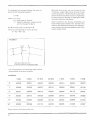
To illustrate this concept further, the error is
given by the following equation:
E= 8h
where E = error,
8 = pitch angle in radians
h = distance between working plane
and the measuring plane.
A & B are radii, and C is parallel to B.
Here, AC corresponds to the arc of error:
E = AC = AS - DE.
I
Machine tool errors are not limited to old
machines. Large table errors can exist in new
machines as well. Askilled machinist can iden
tify errors of his machine and can compensate
for them by either leading or lagging the table
and meet required tolerances.
Table movement will deviate somewhat and
there will be some transfererror. Transfererror
refers to the difference between the displace
ment of work place and the displacement of the
scale's reader head.
FIGURE 27
~,c -1--~
-8
I
•
J
Typical geometrical error
of miffing machine longitudinal table
For convenience, the following table shows
some resu Its of the error function.
FIGURE 28
SEC.
5 SEC.
15 SEC.
30 SEC.
1 MIN.
3 MIN.
5 MIN.
.5"
.00000
.00001
.00004
.00008
.00015
.00044
.00072
1"
.00000
.00002
.00007
.00015
.00029
.00087
.00145
2"
.00001
.00005
.00015
.00029
.00058
.00175
.00291
4"
.00002
.00010
.00029
.00058
.00116
.00349
.00582
8"
.00004
.00020
.00058
.00116
.00233
.00698
.01164
16"
.00008
.00038
.00116
.00233
.00465
.01396
.02327
Typical machine tool table transfer error
i§
22
M3
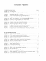
~NDEX
OF FIGURES
100 SERIES DRAWINGS
PAGE
FIGURE 1A
Scale Assembly..........
FIGURE 1 B
Encoder Temporary Alignment SUb-assembly. .
. . . . . . . . .. . . . .
1
FIGURE 2
Glass Scale Alignment Procedure....................................
2
FIGURE 3
Longitudinal Scale Assembly Mounting Procedure...................
4
FIGURE 4A
Bridgeport Longitudinal Axis Encoder Mounting Procedure...........
4
FIGURE 4B
Lagun Type Longitudinal Axis Encoder Mounting Procedure.. . . .. . ..
4
FIGURE 4C
Bridgeport Longitudinal Axis Cross Section View.. . . .. . . .. . . . . . .. . . ..
4
FIGURE 5A
Universal Cross-Travel Mounting Procedure..........................
5
FIGURE 5B
Universal Cross-Travel Mounting Procedure..........................
5
FIGURE 5C
Universal Cross-Travel Mounting Procedure..........................
5
FIGURE 6
Bridgeport Type Cross-Travel Mounting Procedure................. ..
6
FIGURE 7
Universal Cross-Travel Mounting Cross Section......................
6
FIGURE 8
Bridgeport Cross-Travel (Y Axis) Encoder Mounting Procedure.......
7
1
..
XT 200 SERIES DRAWINGS
FIGURE 14
XT200 lV1iniscale Assembly.
.
. .. . . . ..
7
FIGURE 15
XT200 Series Housing Alignment Procedure......
.
... . ..
8
FIGU RE 16
Longitudinal Scale Assembly Mounting Procedure. . . . . . . . . . . . . . . . . . .
9
FIGURE17
XT200SeriesCrossSection
10
FIGURE 18
Bridgeport Cross-Travel (Y Axis) Mounting Procedure
11
FIGURE 19
Universal Cross-Travel Mounting Procedure
12
FIGURE 20
Display Mounting Procedure
13
FIGURE 21
Typical Lathe Installation
FIGURE 22
Typical Grinder Installation
16
FIGURE 23
Typical Milling Machine Quill Installation
16
FIGURE 24
Typical Milling Machine Knee Installation
17
FIGURE25
RP6,TypeEncoder
21
FIGURE 26
Typical Overhanging Table Travel Arc
21
FIGURE 27
Typical Geometrical Error of Milling Machine Longitudinal Table
22
FIGURE 28
Typical Machine Tool Table Transfer Error
22
.
_
,
15
23
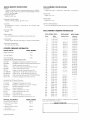
DIGITAL READOUT SPECIFICATION
SCALE ASSEMBLY SPECIFICATIONS
DISPLAY:
7 digits and ± sign per axis using high performance nitrogen
doped, GcAsp on GapO.560" LED's that are readable to over20'
at 150° viewing angle.
DISPLAY RESOLUTION:
0.0005" or 001 mm.
ACCURACY:
0.0003" total within 3', Beyond 3'., add 0.0001" total per foot.
MAXIMUM DISPLAY RANGE:
INCH: ± 999.9995. METRIC:
REPEATABILITY:
0.0004",0.01 mm
± 9999.99 mm.
CIRCUITRY:
All integrated circuitry, including LSI and CMOS logic
technology.
RESPONSE SPEED:
50 kHz
RESOLUTION:
0.0005",0.01 mm
OUTPUT CHARACTERISTICS:
Two 5 volt quadrature square waves that are TIL compatible.
SCALE ASSEMBLY ORDERING INFORMATION
SIGNAL INPUTS:
One encoder/instrument interface connector per axis.
OPERATING TEMPERATURE:
DoC (32°F) to 50°C (122°F)
COUNTER ORDERING INFORMATION
MODEL NUMBER
Single Axis Display
711A
Two Axis Display
712A
Three Axis Display
Hardware Kits 100 Series Regular Scales:
713A
509-00BP
509-00BPC
509-EX
509-00-K
509-KDIA
509-00l
509-30SMAX
509-34SMAX
509-00-WIX
509-XX-100
Bridgeport mounting hardware kit and arm
Bridgeport Universal mounting hardware kit & arm
Excello hardware kit and arm
Knee Z axis mounting hardware kit and arm
Kondia hardware kit and arm
Lagun mounting hardware kit and arm
Supermax 30" travel hardware kit and arm
Supermax 34" travel hardware kit and arm
Wells mounting hardware kit for 747,847,887,lndex
Universal hardware kit and arm for mills
Hardware Kits 200 Series Miniscoles:
515-M-BP
515-M-BPC
515-M-EX
515-M-K
515-M-KDIA
515-M-L
515-M-Q
515-M-SMAX
515-XX-200
Bridgepcrt hardware kit and arm
Bridgeport hardware kit and arm Universal
Excello hardware kit and arm
Knee hardware kit
Kondia hardware kit and arm
Lagun hardware kit and arm
Quill hardware kit
Supermax hardware kit and arm
Universal hardware kit and arm for mills
OPTIONAL ACCESSORIES
Instrument Mounting Arm
Instrument Control Cable
15' Extension
instrument Control Cable
20' Extension
Stiielded Power Cord
SARGON 202412/3-85
MODEL NUMBER
10500
190-15
190-20
190-PC
MODEL NUMBER
Regular Scales
2"
4"
5"
6"
8"
10"
12"
14"
16"
18"
20"
24"
26"
28"
30"
32"
36"
40"
42"
46"
48"
50"
54"
60"
62"
65"
70"
80"
90"
96"
100"
110"
120"
130"
140"
150"
POWER INPUT:
115VAC ± 20%, 48-62Hz switehable to 100,230 and 240 VRMS.
DIGITAL DISPLAY
SCALE ASSEMBLY LENGTH
Inches
Metric
( 50 mm)
( 100 mm)
( 125 mm)
( 150 mm)
( 200 mm)
( 250 mm)
( 305 mm)
( 355 mm)
( 405 mm)
( 455 mm)
( 505 mm)
( 610 mm)
( 660 mm)
( 700 mm)
( 760 mm)
( 800 mm)
( 915 mm)
(1000 mm)
(1065 mm)
(1165mm)
(1220 mm)
(1310 mm)
(1370 mm)
(1525 mm)
(1550 mm)
(1650 mm)
(1778 mm)
(2000 mm)
(2250 mm)
(2400 mm)
(2500 mm)
(2750 mm)
(3000 mm)
(3250 mm)
(3500 mm)
(3750 mm)
........
........
........
100-06-X
100-08-X
100-10-X
100-12-X
........
100-16-X
100-18-X
100-20-X
100-24-X
........
100-28-X
100-30-X
100-32-X
100-36-X
1OO+X
100-42-X
........
100-48-X
........
........
MODEL NUMBER
Miniscale
XT-250-02
XT-250-04
XT-250-05
XT-250-06
XT-250-08
XT-250-1O
XT-250-12
XT-250-14
XT-250-16
XT-250-18
XT-250-20
XT-250-24
XT-250-26
XT-250-28
XT-250-30
XT-250-32
XT-250-36
XT-250--40
XT-250-42
XT-250-46
XT-250-48
XT-250-50
XT-250-54
100-60-X
100-62-X
100-65-X
100-70-X
1oo-80-X
100-90-X
100-96-X
1OO-100-X
100-110-X
100-120-X
100-130-X
100-140-X
100-150-X
Sargon Industries reserves the right to change specifications. designs
prices and models without notice
DEALER IN YOUR AREA:
l