1
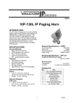
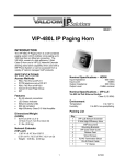
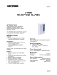
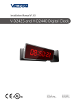
Issue 6
V-VCU
CLOCK CONTROLLER PACKAGE
GENERAL
The Valcom Clock Controller provides 24VDC
power as well as automatic synchronization and
correction to Valcom clocks when used with a
V-DCPI Digital Clock Protocol Interface, a
V-D11025 2.5” Digital Clock, a V-D11040 4.0”
Digital Clock, a V-WMC Wireless Master Clock
Transceiver, a V-GPS GPS Receiver, a VERCA
Remote Card Adapter or a clock output from
another V-CCU.
Environmental
Operating Temperature:
-0 to +40° C
Humidity:
0-95% non-precipitating
PACKAGE INCLUDES
1 Valcom V-CCU Clock Controller
1 Valcom 24V Power Supply V-C6124P
1 24V Wiring Harness
1 6-Pin Silver-Satin Cord
1 6-Pin RJ-11 Wiring Block
Wiring Requirements
24AWG UTP, CAT 3/5/5E/6
INSTALLATION
Precautions
Failure to observe the following precautions could
result in damage to the V-CCU.
Make all connections to the V-CCU and
associated equipment with the input power
removed. Check and verify all connections
before applying power.
SPECIFICATIONS
Outputs
Three individual 2 Amp, 24VDC outputs are
provided to power up to 120 Valcom Analog clocks,
36 Valcom 2.5” Digital Clocks or 30 Valcom 4.0”
Digital Clocks.
V-C6124P Mounting Instructions
Inputs
Locate an area on the wall capable of
supporting the weight of the power supply
(approximately 5 pounds) within six feet of an
AC receptacle.
Using the mounting bracket as a template, mark
the two slotted holes on the mounting surface.
Using the two #8 screws enclosed, mount the
bracket to the mounting surface as shown
(See Figure 1).
Slide the V-C6124P onto the mounting bracket.
Correction data
24VDC input power
Features
Supports two wire clock operation
Individual current limited 2 Amp outputs
User selectable correction intervals
Data error LED indicators
Power/Data output LED indicators
Dimensions/Weight
V-C6124P Wiring Instruction
2.63”H x 12.36”W x 7.75”D
(6.7cm H x 31.4cm W x 19.7cm D)
7lbs. ( 3.2 kg ) (with power supply)
Plug the AC cord into the V-C6124P only.
(Do NOT plug into the AC outlet)
Plug the wiring harness packaged with the
V-CCU into the output connector of the
V-C6124P (See Figure 1).
Power Requirements
The V-CCU requires 24VDC 2 Amps per output
(V-C6124P included).
1
947036
V-CCU Mounting
Plug the 24V wiring harness from the
V-C6124P into the POWER IN connector of the
V-CCU.
Position the V-CCU directly below the
V-C6124P. Using the 24V wiring harness as a
measure, align the V-CCU under the
V-C6124P where the wiring harness is not
stressed (See Figure 1).
Using the unit as a template, mark the mounting
hole locations on the mounting surface.
Disconnect the wiring harness and mount the
V-CCU to the wall.
V-CCU Wiring
Re-attach the 24V harness to the V-CCU.
Dipswitch functionality requires that 24V be
applied to all three 24V inputs.
Connect the data out from a V-DCPI Digital
Clock Protocol Interface, a V-D11025 2.5”
Digital Clock, a V-D11040 4.0” Digital Clock, a
V-WMC Wireless Master Clock Transceiver, a
V-GPS GPS Receiver, a VERCA Remote Card
Adapter or a clock output from another V-CCU
to the “DATA IN” RJ-11 on the V-CCU. Dress
the wires behind the V-CCU as shown.
NOTE: The V-CCU data input is not polarity
sensitive. See FIGURE 2 for data
connection detail.
Dress the peripheral clocks home run wiring
behind the V-CCU as shown (See Figure 1).
If your system will use more than one
V-CCU, you must connect a common
ground. Simply connect one of the negative
(-) outputs of each V-CCU’s V-C6124P power
supply together.
Connect the home runs to the plug-in terminal
strip provided.
NOTE: Maximum of 2 Amps per Clock output.
Plug the terminal strip into the Clock Output
connector on the V-CCU.
DO NOT APPLY POWER YET! The clock
correction interval must be set prior to
energizing the unit. See Setup and
Programming.
2
947036
Otherwise, when initial setup is complete, change
the V-CCU dipswitches to send data every hour.
Setup and Programming
If using a V-GPS, a V-WMC or a V-D110XX
Digital Clock as a data source, set the clock
data correction interval on these units for “one
second”. (Refer to the individual product
manuals for details). If using a V-DCPI or a
VERCA as a data source, program the Valcom
intercom to provide “digital out” and “24-Hour
Enhanced”.
Using the V-CCU dipswitches set the desired
clock correction intervals using chart 1 below.
Switch
1
Down
Up
Up
Up
Switch
2
Up
Down
Up
Up
Switch
3
Up
Up
Down
Up
Pin 1 24V out to V-DCPI
Pin 2 GND out to V-DCPI
Pin 3 Data
Pin 4 Data
Pin 5 GND out to DCPI
Pin 6 24V out to V-DCPI
FIGURE 2: DATA IN RJ-11 DETAIL
Data is connected via the two center pins of the
“DATA IN” RJ-11 connector. Electrical shorting of
any RJ-11 pins or terminations may result in unit
failure.
Switch
4
Up
Up
Up
Down
1 SEC
1 MIN
10 MIN
1 HR
SLAVE
Down
Down
Down
Down
MODE
CHART 1: CORRECTION INTERVAL
The 24V and GND connections are provided as a
power source for the V-DCPI Digital Protocol
Interface.
Initialization Self Test
Plug the V-C6124P into the AC receptacle. After
approximately two seconds, the three RED LEDs
on the V-CCU should blink twice and then
extinguish when the unit begins to receive data
from the master clock. This indicates that the unit is
energized and operating properly.
Spare pairs in multi conductor talkback speaker
cables, as are often used for classrooms, may be
used to distribute Valcom 2-wire digital clock
correction signals. Do Not use spare pairs in multi
conductor one-way speaker cables to distribute
clock correction signals – use dedicated clock
cabling for one-way speaker areas.
NOTE: During the power up self-test, it is normal
for the LEDs to blink out of sequence.
Dedicated clock cabling should also be used for
digital display clocks that will be utilized to display
the word “Fire” or “Bell”.
During initial setup, the V-CCU dipswitches should
be set to send data every second.
After the initialization self test, the three GREEN
LEDs should illuminate, indicating that 24V is being
supplied to the clocks. The GREEN LEDs will
flicker periodically following data transmission to the
clocks.
Once initial setup is complete:
OPERATION
The V-CCU provides 24VDC power and correction
data over a single pair of wires to Valcom clocks.
The unit can be programmed to send the correction
data out once every second, every minute, every
ten minutes or every hour. RED LEDs indicate that
the unit is not receiving input data. GREEN LEDs
indicate that 24VDC is being supplied to the clocks.
The GREEN LEDs will flicker when correction data
is supplied to its respective output.
If the V-CCU is connected to the clocks through
dedicated cabling then the V-CCU dipswitches
should be set to send data every ten minutes.
If the V-CCU is used with a Class Connection
VECPU-5, a VECPU rev 4.02 or higher or a VCPU4 rev 3.16 or higher, then the V-CCU
dipswitches should be set to send data every ten
minutes.
Master/Slave Mode
If the V-CCU is used with digital display clocks that
will be utilized to display the word “Fire” or “Bell”,
then the V-CCU dipswitches should be set to send
data every second.
Systems requiring multiple V-CCUs may be wired in
a master/slave configuration with one of the clock
outputs connected to the “Data In” of one or more
slaves. Slave units must be mounted within 500
feet of the master and must have all of their
dipswitches set to the “down” position (slave mode).
3
947036
Option switches
are used to set the
frequency of data
transmission and
slave mode (see
chart 1)
Data error LEDs are
normally off and
illuminate to indicate
the absence of input
data.
Connect to V-C6124P
power supply using the
cable supplied in the
V-VCU package.
Visit www.valcomclocks.com for
clock connection diagrams and
CAD drawings.
Data in may be provided
from a V-DCPI Digital
Clock Protocol Interface, a
V-D11025 2.5” Digital
Clock, a V-D11040 4.0”
Digital Clock, a V-WMC
Wireless Master Clock
Transceiver, a V-GPS
GPS Receiver, a VECRA
Remote Card Adapter or a
clock output from another
V-CCU.
Data output LEDs
flicker each time data
is sent to the clocks.
3 clock outputs are
provided. Each output
can be connected to
up to 40 Valcom
Analog clocks, 12
Valcom 2.5” Digital
Clocks or 10 Valcom
4.0” Digital Clocks.
2 Amps are available
per output.
The V-CCU is not field repairable. Valcom, Inc.
maintains repair facilities in Roanoke, VA. Should
repairs be necessary, attach a tag to the unit clearly
stating your company name, address, phone
number, contact person and the nature of the
problem. Send the unit to:
Valcom, Inc.
Repair and Return Dept.
5614 Hollins Road
Roanoke, Virginia 24019-5056
TECHNICAL SUPPORT
When trouble is reported, verify that power is being
supplied to the unit and that there are no broken
connections. Check input power for correct polarity.
Assistance in troubleshooting is available from the
factory. When calling, you should have a VOM,
several clip leads and be calling from the site. Call
(540) 563-2000 and press 1 for Technical Support
or visit our website at www.valcom.com.
VALCOM LIMITED WARRANTY
Valcom, Inc. warrants its products to be free from defects in materials and workmanship under conditions of normal use and service for a period of one year from
the date of shipment. The obligation under this warranty shall be limited to the replacement, repair or refund of any such defective device within the warranty
period, provided that:
1. inspection by Valcom, Inc. indicates the validity of the claim;
2. the defect is not the result of damage, misuse or negligence after the original shipment;
3. the product has not been altered in any way or repaired by others and that factory sealed units are unopened (a service charge plus
parts and labor will be applied to units defaced or physically damaged);
4. freight charges for the return of products to Valcom are prepaid;
5.
all units 'out of warranty' are subject to a service charge. The service charge will cover minor repairs (major repairs will be subject to
additional charges for parts and labor).
This warranty is in lieu of and excludes all other warranties, expressed or implied and in no event shall Valcom, Inc. be liable for any anticipated
profits, consequential damages, loss of time or other losses incurred by the buyer in connection with the purchase, operation or use of the product.
This warranty specifically excludes damage incurred in shipment. In the event a product is received in damaged condition, the carrier should be notified
immediately. Claims for such damage should be filed with the carrier involved in accordance with the F.O.B. point.
Headquarters:
Valcom, Inc.
5614 Hollins Road
Roanoke, VA 24019-5056
Phone: (540) 563-2000
FAX: (540) 362-9800
4
947036