1
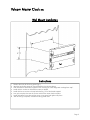
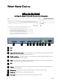
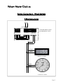
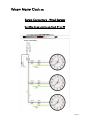
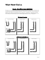
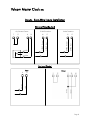
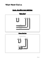
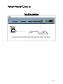
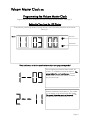
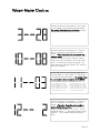
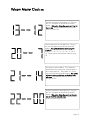
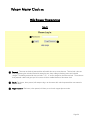
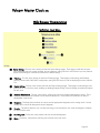
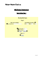
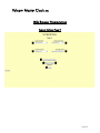
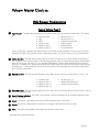
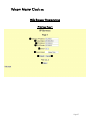
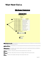
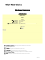
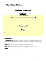
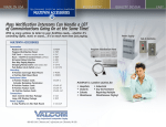
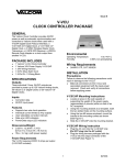
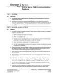
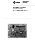
Valcom Master Clock (V2) V-WMCA V-GPSA V-GPS-TX Valcom, Inc. 5614 Hollins Road Roanoke, VA 24019 Valcom Master Clock (V2) Table of Contents Installation Instructions Wall Mount…………….....………………………………………................. Page 3 Before You Get Started Rear View of Unit…………..………………………………………................ Page 4 System Connection Diagrams 2 Wire Communication.......................................................................... Page 5 Sync Wire Communication…………………………………………………... Page 6 Input Connections Sync-Wire Inputs..................................................................................... Pages 7 - 9 Patch Cable Installation.......................................................................... Page 10 Programming the Valcom Master Clock Setting the Time...................................................................................... Setting the Date...................................................................................... Technical Mode...................................................................................... Setting the RS485 Data Rate.................................................................... Setting Daylight Savings Time.................................................................. Setting 12 or 24 Hour Mode................................................................... Setting Clock #1 Relay Output................................................................ Setting Clock #2 Relay Output................................................................ Setting the Primary Input.......................................................................... Setting the Secondary Input..................................................................... Setting the Offset.................................................................................... Setting the Bias Seconds.......................................................................... Setting Once a Day Pulse Input................................................................ Sending Diagnostics............................................................................... Sync-Wire Protocol Definitions................................................................. Page 11 Pages 11-12 Page 12 Page 12 Page 12 Page 13 Pages 13-14 Pages 14-15 Page 15 Page 16 Page 16 Page 16 Pages 16 - 17 Page 18 Page 18 Log-In.................................................................................................... Main Menu............................................................................................ Technician Level..................................................................................... System Settings....................................................................................... IP Settings.............................................................................................. Clock Features....................................................................................... Database Maintenance........................................................................... Page 20 Page 21 Page 22 Pages 23 - 26 Pages 27 - 30 Page 31 Page 32 Web Browser Programming Support Frequently Asked Questions..................................................................... Page 33 Troubleshooting..................................................................................... Page 34 Page 2 Valcom Master Clock (V2) Wall Mount Installation Fig 1 Instructions 1. 2. 3. 4. 5. 6. 7. 8. Remove the cover of the wiring panel (Fig 1). Mark the four drilling points on the wall based on the drawing above. Drill the holes for the anchors supplied in the mounting kit at the designated markings from step 1. Install the four anchors in the holes that were just drilled. Install the first two screws in the top holes leaving 1/8” of the thread exposed. Line up the top key slots over the screws and lock the master clock into place. Install the bottom screws through the wiring access panel and tighten into place. After all wiring is complete, re-install the wiring panel cover. Page 3 Valcom Master Clock (V2) Before You Get Started Installing the Master Clock with the Line Cord Receptacle 6” Rear View of Unit Remainder of cord not shown 0.5” Caution! Do not plug in the power cord until the following steps are completed. 1. 2. 3. 4. The square knockout on the wiring chassis must be removed. The Heyco bushing must be attached to the power cord as shown. Use pliers to push both halves of the bushing together until they lock. Put the wires through the knockout and push the bushing into the metal until it locks into place. The word Heyco on the bushing faces up. Put each wire into the supplied connector and tighten the screws. The wiring label located on the chassis will show where to connect the wires. Rear View of Unit 1 2 3 4 5 6 7 8 9 10 1 N/A 2 N/A 3 Clock 1 & 2 Sync-Wire Outputs - This terminal block is where connections would be landed for Clock 1 and Clock 2 sync-wire communication relay outputs. 4 RS485 Input/Output - This terminal block is where connections would be landed for RS485 communication to and from other Valcom systems. 5 Inputs - This terminal block is where connections would be landed to use the Valcom Master Clock as a slave clock when being controlled by another system. N/A 6 7 Ethernet - This RJ45 jack is used for connecting the master clock to a network for programming and/ or timekeeping capabilities. 8 GPS Antenna - This port is for connecting the GPS Antenna (V-GPSA or V-GPS-TX only). 9 RS232 Port- This RS232 port is used for debugging only. 10 Power Input- This power outlet is used to power up the Valcom master clock. Page 4 Valcom Master Clock (V2) System Connections - Wired Systems 2 Wire Communication 19 18 DATA IN V-C6124P V-CCU 24 volt outputs + - + - + - 24 VDC IN + - + - + - V-C6124P and the V-CCU are ordered as a V-VCU 2 Wire Digital Output to Clocks Orange Yellow V-D2425 or V-D2440 Black White V-A2412 or V-A2416 Page 5 Valcom Master Clock (V2) System Connections - Wired Systems Sync-Wire Communication via Clock #1 or #2 10 Amp Contact Rating Page 6 Valcom Master Clock (V2) Inputs - Sync-Wire Inputs Installation This system can accommodate both a primary and secondary (for backup) auxiliary time synchronization input. The following protocols cannot be used simultaneously: 59 minute sync, 58 minute 1-4 sync, National Time/ Rauland, Dukane Digital, Rauland Digital and once a day Pulse. An example of a configuration would be SNTP being the primary input and 58 minute correction being a secondary input. Setting the primary source to 59 minute sync and the secondary source to Dukane digital would be an incorrect configuration. 59 Minute Correction 12 16 N.O. 17 15 17 24VAC Hot 8 24VAC Interface 24VAC Neutral 17 110VAC Neutral 7 110VAC Interface 110VAC Hot Dry Contact Closure COM 58 Minute Corrections 1-4 N.O. 12 16 17 15 17 24VAC Hot 8 24VAC Interface 24VAC Neutral 17 110VAC Hot 7 110VAC Interface 110VAC Neutral Dry Contact Closure COM Page 7 Valcom Master Clock (V2) Inputs - Sync-Wire Inputs Installation National Time/Rauland 16 17 15 17 24VAC Hot N.O. 12 24VAC Neutral 8 24VAC Interface 110VAC Hot 17 COM Rauland Digital Input Output 17 +5V 11 Dig Line 7 110VAC Interface 110VAC Neutral Dry Contact Closure Page 8 Valcom Master Clock (V2) Inputs - Sync-Wire Inputs Installation Dukane Digital 7 17 14 13 8 Reset Minute Pulse Ground Once a Day Pulse Dry Contact Closure 7 17 8 12 N.O. COM Page 9 Valcom Master Clock (V2) Patch Cable Installation Fig 1.1 Wall Jack to Network 1) Connect a patch cable to the RJ45 port on the Valcom Master Clock as shown in Fig 1.1. 2) Connect the other end of the patch cable to an Ethernet jack connected to the network. Page 10 Valcom Master Clock (V2) Programming the Valcom Master Clock Programming may be accomplished manually or through the web interface. See page 19. Setting the Time from the LED Display To set the time, press the top button to change the hour and/or the bottom button the set the minute. See Fig 2.1. Fig 2.1 Set Hour Set Minute *Press both buttons on the front panel simultaneously to enter programming mode.* Once programming mode has been entered, the number “1” will appear in the far left position. This prompt allows the user to set the year. Use the bottom button to scroll from “00-99” on the display and set the year. Press the top button to enter option 2. The number “2” will appear on the left side of the LED display. This prompt allows the user to set the month. Use the bottom button to scroll between “01-12”. Page 11 Valcom Master Clock (V2) Press the top button to enter option 3. The number “3” will appear on the left side of the LED display. This prompt allows the user to set the day. Use the bottom button to scroll between “01-31”. Press the top button to enter option 10. The number “10” will appear on the left side of the LED display. This prompt allows the user to enter into technical mode. If technical mode is desired, press the bottom button until “08” is reached. Setting option 10 to “08” will allow the user access to options 11-13 when the top button is pressed. Any other value will go directly to option “20” when the top button is pressed. Press the top button to enter technical mode which starts with option 11. The number “11” will appear on the left side of the LED display. This prompt allows the user to set the data transmission for the RS485. Press the bottom button to scroll between “01-12”. 01 - Data is transmitted every second 02 - Data is transmitted every 5 seconds 03 - Data is transmitted every 10 seconds 04 - Data is transmitted every 15 seconds 05 - Data is transmitted every 30 seconds 06 - Data is transmitted every minute 07 - Data is transmitted every 2 minutes 08 - Data is transmitted every 5 minutes 09 - Data is transmitted every 10 minutes 10 - Data is transmitted every 15 minutes 11 - Data is transmitted every 30 minutes 12 - Data is transmitted every hour Press the top button to enter option 12. The number “12” will appear on the left side of the LED display. This option allows the user to enable or disable Daylight Savings Time. Press the bottom button to scroll between “d”, “1”, or “2”. “d” will disable this option. “1” will enable daylight savings pre 2007. “2” will enable daylight savings post 2007. Page 12 Valcom Master Clock (V2) Press the top button to enter option 13. The number “13” will appear on the left side of the LED display. This option allows the user to set 12 or 24 hour mode. Press the bottom button to scroll between “12” and “24”. Press the top button to enter option 20. The number “20” will appear on the left side of the LED display. This option allows the user to program Clock #1. Press the bottom button to scroll through “1”, “2”, “3”, “4”, “5”, “6”, “7”, “8” & “9”. Please refer to relay selection mode on page 18. This option is only available if “8” is selected in option 20 for once a day pulse. Press the top button to enter option 21. The number “21” will appear on the left side of the LED display. This option allows the user to set the hour at which the relay will close. Press the bottom button to scroll through “00-23”. Press the top button to enter option 22. The number “22” will appear on the left side of the LED display. This option allows the user to set the minutes at which the relay will close. Press the bottom button to scroll through “00-59”. Page 13 Valcom Master Clock (V2) Press the top button to enter option 23. The number “23” will appear on the left side of the LED display. This option allows the user to set the seconds at which the relay will close. Press the bottom button to scroll through “00-59”. Press the top button to enter option 24. The number “24” will appear on the left side of the LED display. This option allows the user to set the duration (in seconds) that the user wishes the relay to close. Press the bottom button to scroll through “00-99”. Press the top button to enter option 25. The number “25” will appear on the left side of the LED display. This option allows the user to program Clock #2. Press the bottom button to scroll through “d”, “1”, “2”, “3”, “4”, “5”, “6”, “7” & “8”. Please refer to relay selection mode on page 18. This option is only available if “8” is selected in option 25 for once a day pulse. Press the top button to enter option 26. The number “26” will appear on the left side of the LED display. This option allows the user to set the hour at which the relay will close. Press the bottom button to scroll through “00-23”. Page 14 Valcom Master Clock (V2) Press the top button to enter option 27. The number “27” will appear on the left side of the LED display. This option allows the user to set the minutes at which the relay will close. Press the bottom button to scroll through “00-59”. Press the top button to enter option 28. The number “28” will appear on the left side of the LED display. This option allows the user to set the seconds at which the relay will close. Press the bottom button to scroll through “00-59”. Press the top button to enter option 29. The number “29” will appear on the left side of the LED display. This option allows the user to set the duration (in seconds) that the user wishes the relay to close. Press the bottom button to scroll through “00-99”. Press the top button to enter option 30. The number “30” will appear on the left side of the LED display. This option allows the user to select the primary auxiliary input. Press the bottom button to scroll between “1-13” to select the input. 00 - Real Time Clock 01 - SNTP 02 - 59 Minute Correction 03 - 58 Minute Correction (1) 04 - 58 Minute Correction (2) 05 - 58 Minute Correction (3) 06 - 58 Minute Correction (4) 07 - National Time/Rauland 08 - Dukane 09 - Rauland Digital 10 - Wireless Repeater 11 - Once a Day Pulse* 12 - GPS 13 - RS485 * - Selecting this allows access to options 34-36 Page 15 Valcom Master Clock (V2) Press the top button to enter option 31. The number “31” will appear on the left side of the LED display. This option allows the user to select the secondary auxiliary input. Press the bottom button to scroll between “1-13” to select the input. 01 - SNTP 02 - 59 Minute Correction 03 - 58 Minute Correction (1) 04 - 58 Minute Correction (2) 05 - 58 Minute Correction (3) 06 - 58 Minute Correction (4) 07 - National Time/Rauland 08 - Dukane 09 - Rauland Digital 10 - Wireless Repeater 11 - Once a Day Pulse* 12 - GPS 13 - RS485 * - Selecting this allows access to options 34-36 Press the top button to enter option 32. The number “32” will appear on the left side of the LED display. This option allows the user to set the offset of the user’s time zone location. Press the bottom button to scroll through “-12 to 12”. See Fig 3.1 on page 23 for examples of common offsets. Press the top button to enter option 33. The number “33” will appear on the left side of the LED display. This option allows the user to set the bias seconds which allows the user to adjust the input’s time plus or minus 7500 seconds. Press the bottom button to scroll through “-9999 to 7500”. Press the top button to enter option 34. The number “34” will appear on the left side of the LED display. This option allows the user to set the hour that the time is to go to when Once A Day Pulse is selected. Press the bottom button to scroll through “00-23”. *This option is only available if option 30 or 31 is set to 11. Page 16 Valcom Master Clock (V2) Press the top button to enter option 35. The number “35” will appear on the left side of the LED display. This option allows the user to set the minutes that the time is to go to when Once A Day Pulse is selected. Press the bottom button to scroll through “00-59”. *This option is only available if option 30 or 31 is set to 11. Press the top button to enter option 34. The number “34” will appear on the left side of the LED display. This option allows the user to set the seconds that the time is to go to when Once A Day Pulse is selected. Press the bottom button to scroll through “00-59”. *This option is only available if option 30 or 31 is set to 11. Press the top button to enter option 40. The number “40” will appear on the left side of the LED display. This option displays the last time the clock received an input signal (in hours). The display will be between 00 - 99. This option is read only. It cannot be modified. Press the top button to enter option 44. The number “44” will appear on the left side of the LED display. This option displays whether the clock is receiving an Internet Connection. A “01” will appear on the right side if the master is receiving an Internet Connection. A “00” will appear on the right side if it is not receiving an Internet Connection. This option is a read-only option. Page 17 Valcom Master Clock (V2) Press the top button to enter option 50. The number “50” will appear on the left side of the LED display. This option allows the user to enter diagnostic mode. Press the bottom button to scroll between “E - d”. Setting the option to “E” will enable the option and will enter diagnostic mode. Setting the option to “d” will disable the option and upon depressing the top button, the clock will return to the time. Press the top button to enter option 51. The number “51” will appear on the left side of the LED display. This option allows the user to send the diagnostic to the slave clocks. Pressing the bottom button will scroll from “1-5 and 9”. 01 - Protocol Verification 02 - Comprehensive Test 03 - Manufacturer’s Default 04 - Combination of 02 & 03 (button must be pressed on V-A2412/V-A2416) 05 - Combination of 02 & 03 (no need to press button on V-A2412/V-A2416) 09 - Overrides the Previous Diagnostic and Goes Back to the Time Pressing the top button will advance to option 52. The number “52” will appear on the left of the LED display. This option allows the user to set how long (in minutes) that the information display from the diagnostic will stay on the clock. Pressing the bottom button will scroll from “00-60”. Pressing the top button will go back to the displayed time. Page 18 Valcom Master Clock (V2) System Connections - Wired Systems Sync-Wire Communication - Protocol Definitions “1” = 58th minute (1) - The hourly correction for 55 seconds every hour from XX:58:05 to XX:59:00. The daily correction (5 a.m. & 5 p.m.) is ten correction cycles sent to the relay (each for 95 seconds) beginning at 5:05:00, 5:07:00, 5:09:00, 5:11:00, 5:13:00, 5:15:00, 5:17:00, 5:19:00, 5:21:00, and 5:23:00. “2” = 58th minute (2) - The hourly correction for 60 seconds every hour from XX:58:00 to XX:59:00. The daily correction (5 a.m. & 5 p.m.) is twelve correction cycles sent to the relay (each for 65 seconds on and 25 seconds off) beginning at 5:05:00 to 5:22:35. “3” = 58th minute (3) - The hourly correction for 60 seconds every hour from XX:58:00 to XX:59:00. The daily correction (5 a.m. & 5 p.m.) is twelve correction cycles sent to the relay (each for one minute on and two minutes off) beginning at 5:06:00. “4” = 58th minute (4) - The hourly correction for 55 seconds every hour from xx:58:05 to XX:59:00. The daily correction (5 a.m. & 5 p.m.) is 12 correction cycles for 55 seconds. The timings will be 05:03:05, 05:07:05, 05:11:05, 05:15:05, 05:19:05, 05:23:05, 05:27:05, 05:31:05, 05:35:05, 05:39:05, 05:43:05 and 05:47:05. “5” = 59th minute - The hourly correction for 8 seconds every hour from XX:57:54 to XX:58:02. The daily correction (5 a.m. & 5 p.m.) is a 14 second pulse from 5:57:54 to 5:58:08. “6” - National Time & Rauland_1 – The hourly correction is for 25 seconds every hour from XX:00:00 to XX:00:25. The daily correction (6 a.m. & 6 p.m.) is 25 seconds on, 35 seconds off every minute for 24 minutes. “7” = National Time & Rauland_2 – The hourly correction is for 25 seconds every hour from XX:00:00 to XX:00:25. This option only has hourly corrections. “8” - Once a Day Pulse - The Once a Day Pulse allows the user to manually configure when the relay will close and for how long it needs to close for. If this option is selected on either option 20 or 25, and the top button is pressed, a new set of parameters may be accessed to set the Once a Day closure settings. They are the following: Option 21 (Clock 1) & Option 26 (Clock 2) = Set Hour for relay to close Option 22 (Clock 1) & Option 27 (Clock 2) = Set Minutes for relay to close Option 23 (Clock 1) & Option 28 (Clock 2)= Set Seconds for relay to close Option 24 (Clock 1) & Option 29 (Clock 2) = Set Duration for relay to close “9” - Rauland Digital - The relay closes for a half second for every minute that it needs to advance. Page 19 Valcom Master Clock (V2) Web Browser Programming Log-In 1 2 1 2 3 3 Password - There are two levels of passwords that will enable the user to access features. The first level is the user level programming that includes features like setting the time, date, adding and editing events and schedule changes. The default password for the user level is 1111. It can be changed in the technician level. The technician level password is 6063 and gives you full access to all of the enabled features of the master clock. Log In - This button, when pressed, will attempt to log in to the master clock with the password that was entered in the field above. Forgot Password - This button, when pressed, will direct you to the tech support phone number. Page 20 Valcom Master Clock (V2) Web Browser Programming Main Menu 1 2 3 4 5 1 Technician Menu - This link will access the Technician Menu log-in page. The Technician Menu is password protected and has access to system settings, IP settings, as well as feature settings for the master clock. 2 Time - This field is where the current time is displayed. The time can be edited by clicking within the field, and typing in the desired time. The time must be entered in 24 hour format (HH:MM:SS). After typing in the desired time, click the Submit button to set the time on the unit (if there is no input connected). 3 Date - This field is where the current date is displayed. The date can be edited by clicking within the field, and typing in the desired date. The date must be entered in mm/dd/yyyy format. After typing in the desired time, click the Submit button to set the date on the unit (if there is no input connected). 4 Submit - This button, when pressed, will submit the date and time shown on the screen to the master clock. 5 Log Out - This button, when pressed, will log the user out of the browser interface. Page 21 Valcom Master Clock (V2) Web Browser Programming Technician Level Menu 1 2 3 4 5 6 7 8 1 2 3 4 5 6 System Settings - This link, when clicked, will enter the System Settings pages. These pages include the user password, the RS485 data rate, setting the offset, the input selection, setting Clock #1 and Clock #2 sync-wire protocol outputs and resetting the unit back to manufacturer’s default settings. IP Settings - This link, when clicked, will enter the IP Settings pages. These pages include setting the IP address, gateway, subnet mask, DNS, DHCP configuration, setting the NTP servers, as well as displaying the status of the device. Feature Settings - This link, when clicked, will enter the Feature Settings pages. These pages include setting the display format in 12 or 24 hour mode, enabling or disabling Daylight Savings Time and editing the standard durations for each zone. Database Maintenance - This link, when clicked, will bring the user to the Database Maintenance section. This is where all of the events and schedules can be saved and backed up. Saved events and schedules can also be downloaded in this section. Diagnostic - This drop-down list allows the user to send the appropriate diagnostics to the analog clocks. See the analog clock’s manual for descriptions of each diagnostic. Duration - This field is where the user can select how long (in minutes) that the user wants the diagnostic to display on the face of the clock. 7 Start Diagnostic - This button, when pressed, will start the selected diagnostic. 8 Menu - This button, when pressed, will bring the user back to the main menu. Page 22 Valcom Master Clock (V2) Web Browser Programming System Settings Page 1 2 1 3 4 5 6 7 Page 23 Valcom Master Clock (V2) Web Browser Programming System Settings Page 1 (cont.) 1 2 3 4 User Password - This field allows the user to enter a new password for the user level programming. The default is 1111. RS485 Data Rate - These fields allow the user to set how often RS485 will be transmitted from the master clock. Bias Seconds - This field allows the user to offset how many seconds off, plus or minus, the time will be when receiving an input. This field can range between –7500 to 9999 seconds. GMT Offset - This field sets the positive or negative offset for GMT time. For instance, eastern time zone is a negative five hour offset. See Fig 3.1 for typical offsets. Fig 3.1 Time in Greenwich Local Time Positive Offset Negative Offset Philadelphia (Eastern Standard Time) 12:00 p.m. (Noon) 7:00 a.m. 0 5 Chicago (Central Time) 12:00 p.m. (Noon) 6:00 a.m. 0 6 Denver (Mountain Time) 12:00 p.m. (Noon) 5:00 a.m. 0 7 Los Angeles (Pacific Time) 12:00 p.m. (Noon) 4:00 a.m. 0 8 5 Submit - This button, when pressed, will save any changes made on the page. 6 Cancel - This button, when pressed, will clear out any fields and not save any data. 7 Menu - This button, when pressed, will bring the user back to the main menu. Page 24 Valcom Master Clock (V2) Web Browser Programming System Settings Page 2 1 2 3 4 5 6 7 8 Page 25 Valcom Master Clock (V2) Web Browser Programming System Settings Page 2 1 Input Selection - This drop-down list allows the user to select which input will control the master clock. The choices are: Real Time Clock • 58 Minute Sync_3 GPS • 58 Minute Sync_4 SNTP • National Time_Rauland 59 Minute Sync • Dukane Digital 58 Minute Sync_1 • Rauland Digital 58 Minute Sync_2 • Once a Day Pulse If Once a Day Pulse is selected, then fields for hours, minutes and seconds will appear. Enter the time (in 24 hour mode) that the clock is to go to when a once a day pulse is present. It must be a minimum of a two second pulse. 2 3 Backup Selection - This drop-down list allows the user to select a backup input in case of the loss of the primary input. In order to use the Backup Selection, the following protocols cannot be used as both a primary and secondary input: 59 minute sync, 58 minute 1-4 sync, National Time/Rauland, Dukane Digital, Rauland Digital and once a day Pulse. An example of a configuration would be SNTP being the primary input and 58 minute correction being a secondary input. Setting the primary source to 59 minute sync and the secondary source to Dukane digital would be an incorrect configuration. Clock #1 Circuit - This drop-down list allows the user to select the sync-wire output for the Clock #1 circuit. The choices are: 59 Minute Sync* 58 Minute Sync_1* 58 Minute Sync_2* 58 Minute Sync_3* • 58 Minute Sync_4* • National Time_Rauland_1* • National Time_Rauland_2* 4 Clock #2 Circuit - This drop-down list allows the user to select the sync-wire output for the Clock #2 circuit. See #3 above for the list of choices. 5 Reset All Settings to Default - This button, when pressed, will revert all settings back to the default settings that were sent from the factory. 6 Submit - This button, when pressed, will save all of the information to the master clock. 7 Cancel - This button, when pressed, will clear out any changes made and will not save any data. 8 Menu - This button, when pressed, will bring the user back to the main menu. * See page 18 for protocol definitions Page 26 Valcom Master Clock (V2) Web Browser Programming IP Settings Page 1 1 2 3 4 5 6 7 8 9 Page 27 Valcom Master Clock (V2) Web Browser Programming IP Settings Page 1 (cont.) 1 Gateway IP Address - This field allows the user to set the Gateway IP address for the master clock. 2 Subnet Mask - This field allows the user set the Subnet Mask for the master clock. 3 IP Address - This field allows the user to set the IP address for the device. 4 5 DNS Router - This field allows the user to set the DNS Router address. The default address will typically work for most applications, however some modification may be needed for certain networks. DHCP - This drop down list allows the user to turn DHCP on or off. DHCP allows the master clock to look for an IP address on its own if the network has a DHCP server. 6 Device Name - This field allows the user to name the device a unique name. 7 Submit - This button, when pressed, will save all of the information to the master clock. 8 Cancel - This button, when pressed, will clear out any changes made and will not save any data. 9 Menu - This button, when pressed, will bring the user back to the main menu. Page 28 Valcom Master Clock (V2) Web Browser Programming IP Settings Page 2 1 2 3 4 5 6 1 Retry Failed Server After - This field allows the user to specify how many times it will attempt to access the time from a server before it moves on to the next one. 2 Server Addresses - This field allows the user to specify which NTP servers that the master clock will try to acquire time from. 3 Rotate Servers - This checkbox, when checked, allows the master clock to rotate through all the server addresses to access the time on a continual basis. 4 Submit - This button, when pressed, will save all of the information to the master clock. 5 Cancel - This button, when pressed, will clear out any changes made and will not save any data. 6 Menu - This button, when pressed, will bring the user back to the main menu. Page 29 Valcom Master Clock (V2) Web Browser Programming IP Settings Page 3 1 2 3 4 (GPS, SNTP Client) 5 1 MAC Address (Read Only) - This displays the MAC address for the master clock. 2 IP Address - This display the IP address for the master clock. 3 Device Name - This displays the device name for the master clock. 4 Paid Provisioned Features - This displays the options that are enabled on your device. 5 Menu - This button, when pressed, will bring the user back to the main menu. Page 30 Valcom Master Clock (V2) Web Browser Programming Clock Features 1 2 3 4 5 1 2 Display Format - This drop-down list allows the user to select whether they want 12 hour or 24 hour mode to be displayed on the LED display. Daylight Savings Time - This drop-down list allows the user to select which daylight savings time option they want. The option can be disabled, pre-2007 and post-2007. Pre-2007 has the old-style daylight savings time format that was enacted prior to 2007. Post-2007 daylight savings time is the current, newer format that is followed today. 3 Submit - This button, when pressed, will save all of the information to the master clock. 4 Cancel - This button, when pressed, will clear out any changes made and will not save any data. 5 Menu - This button, when pressed, will bring the user back to the main menu. Page 31 Valcom Master Clock (V2) Web Browser Programming Database Maintenance 1 2 3 4 1 Upload Database - This button, when pressed, will upload the current schedules and events, and place it in a file for backup purposes. 2 Choose File - This button, when pressed, will allow the user to browse for the saved .db file that contains the saved events and schedules. 3 Download - This button, when pressed, will download the selected file and reset the master clock with those events and schedules already configured. 4 Menu - This button, when pressed, will bring the user back to the main menu. Page 32 Valcom Master Clock (V2) Frequently Asked Questions Can I use any SNTP server for downloading the time? Yes, any site that sends out the SNTP protocol may be used as an input to the master clock. What browsers are compatible with the Valcom master clock web interface? The Valcom web interface is compatible with Microsoft Internet Explorer, Mozilla Firefox, Safari, Opera and Chrome. Can I connect to the web browser through a cross-over cable? Yes, the Valcom Master Clock can be accessed through a cross-over cable or via a LAN connection. What is the maximum length I can go with the GPS cable? When the GPS option is purchased, a 75 foot cable comes standard with the unit. This is Valcom’s recommended longest distance. What inputs can the Valcom Master Clock accept? The Valcom Master Clock can accept an input from a SNTP server, 59 minute correction, four different versions of the 58 minute correction, National Time/Rauland, Dukane digital, Rauland digital, Valcom Wireless Repeater, Once a Day pulse, GPS and Valcom’s RS485 protocol. Page 33 Valcom Master Clock (V2) Troubleshooting The master clock will not power up. What do I do? Make sure the power cord is securely connected to the power outlet and to the back of the Valcom Master Clock. Upon being connected to power, the master clock should boot up instantly. There is not an on/off switch. What do I do if I cannot connect to the browser? Verify that the IP address your attempting to access is correct. If the IP address is correct, verify that there aren’t any provisions in the firewall preventing you from accessing it. If all else fails, try connecting via a crossover cable. What do I do if the GPS isn’t receiving a signal? Check the antenna to make sure it is in an unobstructed area that is in complete view of the sky. Also, check to make sure the connections on each end of the cable are securely tightened. Lastly, verify that there are no kinks or breaks in the supplied GPS cable. My sync-wire system doesn’t seem to be getting the correct time. What should I do? The clock 1 and clock 2 outputs control the sync-wire systems. Verify that the correct system is set for the designated clock circuit. Protocol details are listed on page 18. Why didn’t my Valcom Master Clock change for Daylight Savings Time? A few things could cause the Valcom Master Clock not to change for Daylight Savings Time. The first item to check is the date to verify if it’s correct. If the date is not correct, the clock will not change. If the date is correct, verify that the clock is set for the correct version of Daylight Savings Time. See page 14 for more information. Page 34