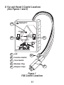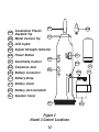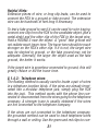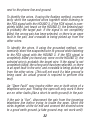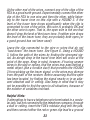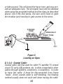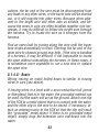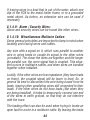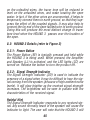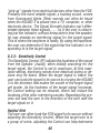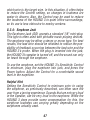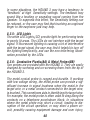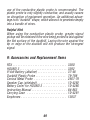
1
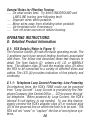
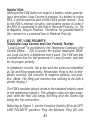
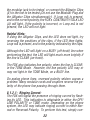
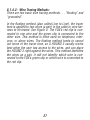
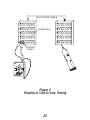
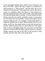
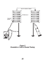
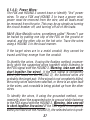
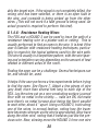
TRIPLETT
Fox &
Hound 3
The
Instruction Manual
1
Fox and Hound 3 Instruction Manual
Table of Contents
1. Introduction . . . . . . . . . . . . . . . . . . . . . . . . . . . . . 2 - 3
2. FOX Features . . . . . . . . . . . . . . . . . . . . . . . . . . . . . . . 3
3. HOUND 3 Features . . . . . . . . . . . . . . . . . . . . . . . . . . . 4
4. Safety Warnings and Cautions . . . . . . . . . . . . . . . . 5 - 6
5. Specifications . . . . . . . . . . . . . . . . . . . . . . . . . . . . 7 - 10
6. Control Locations . . . . . . . . . . . . . . . . . . . . . . . . . 11 - 12
7. Getting Started . . . . . . . . . . . . . . . . . . . . . . . . . . . 13 - 20
8. Operating Instructions: Detailed Information . . . 20- 49
9. Accessories and Replacement Parts . . . . . . . . . . . . . . . 49
10. Warranty . . . . . . . . . . . . . . . . . . . . . . . . . . . . 50 & 51
1: Introduction
The FOX and HOUND 3 wire tracing kit consists of a classic
FOX Tone Generator (Toner) and a newly designed HOUND 3
Inductive Amplifier (Probe). The FOX is a battery operated
handheld lightweight multi-function Toner that can generate
3 different tones (Hi, Lo, and Warble), perform some basic
telephone line tests (loop mA and line polarity), and provides a visual continuity test. The HOUND 3 is a battery operated handheld lightweight Probe, with a thumbwheel Sensitivity control and Signal Strength indicator LED. It improves
on previous designs (the HOUND and HOUND 2) with builtin LED illuminators, a bandpass filter, an earphone jack, and
an easy access battery cover. An included convenient carrying case (with belt loop attachment) provides ease of use
and protective storage for the FOX and HOUND 3.
84-863
2
When used together, the FOX and HOUND 3 aids in identifying, locating, and tracing wires, cables, and other conductors. When the FOX is used to apply a “tone” to a wire, the
HOUND 3 can usually locate the wire inside of, or behind
electrically non-conductive surfaces (plastic, wood, drywall,
etc), up to 12 inches away. The HOUND 3 does not have to
contact a wire to identify it . . . i.e. no stripping needed.
FOXs and HOUNDs have been used in the telephone, electrical, security, sound reinforcement, video, automotive, and
boating industries, to name a few.
2: Key Features of the FOX
•
•
•
•
•
Generates 3 distinct tones usable for wire tracing
Performs a variety of tests on telephone lines
Line powered in Tone Mode
LED Indicator for continuity
Supplies “Talk Power” to allow communicating
between handsets (talksets) or powering a telephone
• Alligator clips and modular plug allow for connection to
stripped wires, terminal panels, or a standard
modular jack (single line)
• Powered by a standard 9V battery (not included)
• One Year Warranty
3
3: Key Features of the HOUND 3
• New Headlights to help light your way in dark areas
and reduce florescent light noise!
• Streamlined Design allows for better access in
hard-to-reach areas
• New Shielded Design to suppress “Feedback Squeal”
• Bandpass Filter to suppress 60Hz and Hi Frequency Noise
• Earphone Jack for use in quiet or noisy environments.
• Improved Sensitivity and Loudness
• Includes New Conductive Plastic Duck-Bill Tip for Safer,
Easier Penetration in cable bundles Metal tip also included
• Easy Access Battery Door
• Adjustable volume / sensitivity control
• LED gets brighter as the signal gets stronger
- LED indication even works when Earphones are used!
• Contains a hi-gain, hi-impedance amplifier
• Capable of identifying the Fox’s tone up to 12 inches away
• Rugged, moisture resistant, mylar cone speaker
• Powered by a standard 9V battery (not included)
• One Year Warranty
4
4: Safety Warnings and Cautions
4.1
Do not connect FOX or HOUND 3 to any source of AC power.
AC voltages above 30 volts can be dangerous, and may result in user injury. The FOX and HOUND 3 is not intended to
trace live AC power lines. The FOX will be damaged if connected to a live AC power line.
4.2
Use care when using the HOUND 3 to probe any wire or cable.
An unexpected dangerous voltage may be present, which
may result in injury to the user.
4.3
Potentials applied to the HOUND 3’s probe may appear,
greatly reduced, at the earphone jack. This could pose a shock
hazard to the user, if for example, the probe is brought in
contact with a high voltage potential.
4.4
The HOUND 3’s metal probe can accidentally short out a circuit that is being tested. Use care when testing live circuitry,
or an accidental short may result in equipment damage or
user injury.
5
4.5
Use caution when working with telephone lines. They can
support dangerous voltages. 50VDC is often present, and
100VAC may be present during ringing. Additionally, telephone lines may support dangerous levels of common mode
voltages. In some circumstances, user injury may result.
4.6
Use caution when working with any long unconnected wire
or cable. Under some conditions, unconnected wires may
“float up” to dangerous potentials, and touching them may
result in user injury.
4.7
Use care when connecting the FOX to any wire or cable. An
unexpected dangerous voltage may be present, which may
result in injury to the user.
4.8
Potentials applied to any connection of the FOX may appear
on other FOX connections. For example, a potential applied
to the RJ-11 plug may appear on the alligator clips. This
could pose a shock hazard to the user, if for example, a telephone cable with 120VAC on it is connected to the FOX . The
120VAC may appear on the alligator clips, and shock the
user.
6
5: Specifications
5.1: FOX Specifications
5.1.1: Telephone Loop mA and Line Polarity Test:
Indication: Red LED lights to indicate presence of Loop mA
in correct polarity
Load: Approx. 13mA at 50VDC (usually less than off-hook
recognition current)
5.1.2: Visual Ring Indication:
Indication: Red LED flashes to indicate ringing
5.1.3: Tracer Tone (with fresh battery):
Waveform:
Square Wave or Differentiated Square Wave Level:
Approx. 8Vpp (+14dBu, 600 Ohm) into an open circuit
(un-terminated cable or telephone line)
Approx. 5Vpp (differentiated) +2dBm into a 600 Ohm
load (terminated telephone line)
Frequencies (3 types):
LO - approx. 800Hz
HI - approx 1000Hz
WARBLE - alternates between LO and HI
5.1.4: Connections:
RJ-11 Plug for connection to telephone lines
Color Coded Alligator Clips for connection to stripped wires
or terminals
7
5.1.5: Visual Continuity:
LED lights when continuity is established
Open Circuit Voltage: 10v max.
Test Current:
35mA max
5.1.6: Talk Power:
Open Circuit Voltage: 10v max.
Current (Short Circuit): 35mA max
Current with 1K Loop: Typically 6mA with new 9v battery
5.1.7: Protection:
Will withstand 56V with 400 Ohms series resistance applied
across outputs. Will withstand 175V peak with 100 Ohms
series resistance, superimposed on 56V, for 100mS (standard telco “ring” signal). DO NOT CONNECT TO LIVE AC
POWER LINES.
5.1.8: Power:
Battery:
Standard 9v Alkaline Battery
(NEDA 1604A, Eveready 522)
Battery Life: Approx 500 hours continuous in
Tone Generator mode
Telephone Line Powered Operation:
Tone Generator operates without 9v battery
installed. Operates from standard telephone
line (46 to 53v, 400 to 1800 Ohms) in
normal or reverse polarity.
8
5.1.9: NiCad Charging Current:
Approx. 9mA
5.1.10: Dimensions:
Case:
3.7"H x 2.4"W x 1.1"T
(93mm x 61mm x 28mm)
Leads:
Alligator Clips: Typically 11 inches long
RJ-11: Typically 9 inches long
5.1.11: Weight:
Less than 7 ounces including battery
5.2: HOUND 3 Specifications
5.2.1: Amplifier
High impedance bootstrapped FET input for high gain and
sensitivity. Incorporates a bandpass filter to improve sensitivity to FOX signals while suppressing 60Hz.
5.2.2: Sensitivity
Detects FOX’s tone up to 12 inches away.
5.2.3: Speaker
1-1/2" mylar coned speaker with high strength alnico magnet is rugged and moisture resistant.
5.2.4: Probes (2 provided)
a) Solid aluminum conical probe for low resistance contact
testing
b) Conductive Plastic duckbill probe with metal threads for
sensitive non-shorting testing.
9
5.2.5: Earphone Jack
Accepts standard 1/8" (3.5mm) mini phone plug, either mono
or stereo. For use with electromagnetic (dynamic) earphones
from 8 Ohms to 2000 Ohms. Automatically mutes loudspeaker when earphone is used. An earphone with a shielded
cable is suggested to reduce the possibility of feedback from
the cable to the probe tip.
5.2.6: Signal Strength Indicator
Bright red LED signal strength indicator maintains sensitivity, even when the earphone is used.
5.2.7: Power
A standard 9 volt alkaline battery (NEDA 1604A, Eveready
522) provides power for all circuitry. The battery is accessible by removing a convenient snap-on door (no tools
required). The HOUND 3 is protected against the accidental
reversal of the battery polarity.
5.2.8: Illumination
2 efficient bright white LEDs powered from separate current
sources provide constant illumination until battery is mostly
depleted (about 6 volts).
5.2.9: Size
1-7/8" dia at speaker, 1-3/8" dia at body, 8-1/4" long with
metal probe, 9-1/4" with conductive plastic probe.
5.2.10: Weight
Less than 8 ounces including battery
10
6: Fox and Hound 3 Control Locations
(See Figures 1 and 2)
A
TRIPLETT
CONTINUITY
TALK
B
TONE
HI
WARBLE
LO
C
OFF / LINE POLARITY
A LED
D
B Function Switch
C Tone Switch
D Modular Plug
E
E Alligator Clips
Figure 1
FOX Control Locations
11
AA
Conductive Plastic
Duckbill Tip
BB Metal Conical Tip
BB
AA
CC
CC
LED Lights
DD
Signal Strength Indicator
EE
Power Button
FF
Sensitivity Control
GG
Earphone Jack
FF
DD
HH
II
GG
JJ
EE
HH
Battery Connector
Battery Strap
JJ Battery Cover
KK Battery (not included)
LL Speaker Cover
LL
Figure 2
Hound 3 Control Locations
12
KK
II
7: Getting Started
7.1: The FOX
7.1.2: Installing a standard 9 volt battery in the FOX
Remove the screw on the back of the case. Remove the
case front. Install / replace the battery. Reassemble the
case.
7.1.3: Using a rechargeable battery in the FOX
The FOX can recharge a 9 volt Nicad battery by using telephone Loop Current (CO power). To use this feature, simply
replace the standard 9 volt battery with a 9 volt Nicad battery. To charge the Nicad, set the FOX to OFF/LINE POLARITY, and connect the alligator clips to the line in Reversed
Polarity (Red to positive and Green to negative). Connecting to the line in Normal Polarity WILL NOT CHARGE the
battery. Approximately 16 hours is required to fully charge
a typical Nicad battery (refer to battery manufacturer specs).
Emergency Fast Charge:
The FOX’s circuitry incorporates a fast charge mode. This
mode is not recommended for casual use because it exceeds
the battery’s nominal charge current and will shorten the
battery’s life. Charging current could be as high as 90 mA.
To use this feature, set the FOX to CONTINUITY / TALK and
connect the alligator clips to a powered line in Reversed
Polarity (Red to positive and Green to negative). DO NOT
charge the battery for more than 30 minutes. Irreversible
13
shortening of the battery’s life may result. DO NOT connect
to the line in Normal Polarity. Damage to the battery may
result.
7.1.4: Testing the Battery in the FOX
After installing the battery, a basic test can be performed to
verify that the battery is powering the FOX. Set Function
Switch (B) to its CONTINUITY / TALK position. Whiles observing LED (A), short alligator clips (E) together. If the battery is OK, the LED will light. A bright LED indicates a fresh
battery . . . a dim LED indicates a weak battery . . . no light
from the LED indicates a dead battery.
Helpful Hint:
Although a weak battery in the FOX may not provide adequate
power to operate several talksets, the TONE feature often
works with a weak battery, and the POLARITY test does not
require a battery to work.
7.2: The HOUND 3
7.2.1: Installing a 9 volt battery in the HOUND 3
Remove Battery Cover (JJ) by pressing the release tab towards probe end of the case. Remove Battery Connector (HH)
and Battery Strap (II). Snap Connector to 9 volt battery and
slide Strap over battery. Position Strap so that the finger tab
is on the side of the battery. Insert battery into HOUND 3
case, placing bottom of battery against foam, and compressing the foam while completing the battery insertion. Lead
wires should be behind battery and “dressed” to allow bat14
tery to be fully inserted. The finger tab on the Strap should
be sticking out of the Battery Compartment. This tab is used
to remove the battery. Fold the tab over, and secure the Battery Cover to the case by inserting the end near the Earphone Jack (GG) first, and snapping the opposite end of the
Cover to the case.
7.2.2: Testing the battery in the HOUND 3
The battery in the HOUND 3 will not last as long as the battery in the FOX. The LED Lights (CC) can be used as a rough
indication of battery charge. With a fresh battery, the Lights
will be bright, and the HOUND 3’s Speaker (LL) will produce
a loud, strong, signal from the FOX. As the battery is drained,
the signal from the FOX will not sound as loud in the HOUND
3’s Speaker. When the Lights begin to dim, the battery should
be replaced.
7.3: A Few Basic Tests
Turn on the FOX by sliding the Function Switch to the TONE
position. Set Tone Switch (C) to the WARBLE position. This
is the position that most users prefer for wire location and
tracing.
Rotate the HOUND’s Sensitivity Control (FF) to its mid-position. Turn on HOUND 3 by pressing and holding the Power
Button (EE). Bring the HOUND 3’s probe (AA or BB) near the
FOX’s alligator clips. The warbling signal from the FOX should
be heard in the HOUND 3’s Speaker (LL). Adjust the Sensitivity Control for the desired loudness. Move the probe of
the HOUND 3 closer to and farther away from the FOX’s alli15
gator clips. Notice how the loudness of the warble sound
increases, and how the brightness of the Signal Strength
Indicator (DD) increases as the probe approaches the alligator clips.
In general, the HOUND 3 is used by bringing it into proximity with the wire/cable that the FOX is connected to, listening
for the TONE signal from the FOX, and moving the HOUND 3
in such a manner as to increase the loudness of the TONE
signal from the HOUND 3’s speaker . . . i.e. searching for
the loudest TONE signal.
The HOUND 3’s Sensitivity Control is usually set to maximum when tracing wires through walls and ceilings, and is
set to a lower setting when in close proximity to the signal
carrying wires. In situations where there is a lot of acoustic
noise, observing the brightness of the LED, or using earphones, may prove more useful than attempting to hear the
signal from the speaker.
Helpful Hints:
It is normal to hear a humming or buzzing noise coming
from the HOUND 3’s speaker when it is in an area with fluorescent lights, neon signs, transformers, etc. In fact, an easy
test to verify the HOUND’s is working is to move it toward an
operating fluorescent light and note that the buzzing sound
gets louder, and the brightness of the LED increases.
If the buzzing sounds from fluorescent lights interfere with
tracing/locating wires, the user may consider turning the fluo16
rescent lights off and using the HOUND 3’s built in lights
(which do not produce any noise).
7.4: Choosing a Probe Tip
The HOUND 3 is supplied with 2 Probe Tips. The metal conical tip provides the strongest signal in most cases, because
it can make a metallic electrical connection with a wire carrying the FOX signal. In some cases, the metal tip can be a
safety hazard . . . because it might short out a live circuit
that the user is “probing”. The metal tip is rather short and
large in diameter, making it difficult to insert into wire bundles
while searching for the target wire.
The conductive plastic duckbill tip will not short out most
electrical circuits. The conductivity of the probe is very low
compared to the metal tip. Additionally, the slender duckbill
shape allows the tip to be inserted into wire bundles while
searching for the target wire. Most users prefer this tip, although it is not quite a rugged as the solid metal tip.
7.5: Earphone Jack
The HOUND 3 has a Jack (GG) for connecting external Earphones (Headphones). When using the external earphones,
the HOUND’s internal speaker is turned off. The earphones
are usually used when there is so much ambient noise that
the speaker cannot be heard, or when the sound of the
speaker may be annoying to others in the vicinity.
17
Helpful Hint:
Almost any type of earphones whose plug will fit into the
Earphone Jack will work. Some types will work better than
others. An earphone with shielded wires is recommended.
Use of earphones with unshielded wires may cause a squealing sound to be heard.
7.6: How it works
The HOUND 3 works by capacitively sensing the electrostatic
field radiated by wires carrying a signal from the FOX. The
greater the radiated field, the better the HOUND 3’s ability to
locate a wire. Anything that reduces the intensity of the field
will impair the HOUND 3’s effectiveness in locating a wire.
In general, several things affect field intensity . . . shielding,
signal (tone) amplitude on the wire, and wire dress. In instances where a system is shielded (shielded wires, metal
junction boxes, metal conduit, etc.), the effectiveness of the
HOUND 3 is impaired. In multi-wire cables, grounded wires,
or wires connected to low impedance circuits, adjacent to
the target wire can act as shields, reducing the HOUND 3’s
ability to sense properly. Spreading the wires apart will reduce the shielding effect and allow the HOUND 3 to work
better. Defects in a cable or wires, such as shorts or opens,
will reduce the signal amplitude and hence the HOUND 3’s
ability to locate the target wire. Terminating a wire or line in
a low impedance also reduces signal amplitude and the
HOUND 3’s locating ability. It is also possible for wire position to cause nullification of the field.
18
If the target wire is connected to other wires and circuits,
for example, to switches, lights, relays, transformers, etc.,
the FOX TONE will pass through these devices and out onto
other wires connected to these devices . . . making tracing
of the target wire very difficult, if not impossible.
In general, the FOX and HOUND 3 cannot be use to trace
wires buried underground or in concrete. This is because
the moisture content of the earth or of concrete allows the
surface to be electrically conductive, causing it to act as a
shield around the buried wire.
Wet drywall, wet cinder block walls, or any wet wall surface
will also shield the FOX signal, preventing the HOUND 3 from
detecting its presence.
The actual wire being wet can shield the signal. The wire can
be wet internally, shielding the signal. This phenomena has
been observed in “Romex” electrical wire. The internal paper separator can get wet from exposure to the weather. The
exterior surface of the Romex can be dry, but because the
internal paper separator is wet, it shields the tracer signal.
Extremely high humidity will damp (collapse) the electrostatic field, reducing the effectiveness of the HOUND 3 in
finding the FOX signal. Condensing atmospheres may even
cause the products to malfunction until they dry out.
The HOUND 3 will not trace wires through a metal conduit.
It can, however, identify the wires after they exit from the
conduit.
19
General Rules for Effective Tracing:
…. Do what works best. Try both LINE/GROUND and
LINE/LINE tracing (see following text).
…. Separate wires when possible.
…. Move wires away from shielding when possible.
…. Un-terminate wire if necessary.
…. Turn off noise sources to reduce buzzing
OPERATING INSTRUCTIONS:
8: Detailed Product Information
8.1: FOX Details (Refer to Figure 1)
The Function Switch (B) sets the basic operating mode. The
3 positions each have several testing functions associated
with them. The follow text describes these test features in
detail. The Tone Switch (C) selects a HI, LO, or WARBLE
tone. The alligator clips (E) and the modular plug (D) allow
the FOX to be connected to a variety of different wires and
cables. The LED (A) provides indication of line polarity and
continuity.
8.1.1: Telephone Loop Current Powering: Line Powering
On telephone lines, the FOX’s TONE mode can be powered
from “Loop Current”. Loop Current is provided by the Telephone Company (the Central Office…. CO) to power the typical telephone. When powered by Loop Current, the FOX’s
internal 9 volt battery is not needed. To use this feature,
simply connect the FOX’s alligator clips (E) or modular plug
(D) to the powered line on which the tone is to be sent. The
FOX will not “seize” or “capture” the line of most phone systems.
20
Helpful Hint:
Although the FOX does not require a battery when generating a tone when Loop Current is present, if a battery is in the
FOX, it will be used as part of the FOX’s power source. Due
to the FOX’s internal circuitry, less battery power is used if
the FOX is connected to the line in Reverse Polarity, i.e. Tip
to Negative, Ring to Positive. Therefore, for greatest battery
life, connect to a powered line in Reverse Polarity.
8.1.2: OFF / LINE POLARITY:
Telephone Loop Current and Line Polarity Testing:
“Loop Current” is provided by the Telephone Company (the
Central Office…. CO) to power the typical telephone. Without Loop Current, a telephone won’t work. The FOX can test
a telephone line for the presence of Loop Current, and test
for its proper polarity.
In telephone circuits, the green and red wires are identified
as Tip and Ring respectively. Remember, Ring is red. In telephone circuitry, the red wire is negative polarity, not positive. (Note: The Ring just mention has nothing to do with a
phone ringing.) .
The FOX’s modular plug is wired in the standard polarity used
in the telephone industry. The alligator clips are also polarized, with the Red clip being the Ring and the Green clip
being the Tip connection.
Referring to Figure 1, set the Function Switch (B) to its OFF/
LINE POLARITY position. Plug the Modular Plug (D) into
21
the modular jack to be tested, or connect the Alligator Clips
(E) to the line to be tested (Do not use the Modular Plug and
the Alligator Clips simultaneously). If Loop mA is present,
and in the correct polarity, the FOX’s CONTINUITY/TALK LED
(A) will light. If the polarity is incorrect, or Loop mA is not
present, the LED will not light.
Helpful Hints:
If using the Alligator Clips, and the LED does not light, try
reversing the positions of the clips. If the LED then lights,
Loop mA is present, and in the polarity indicated by the clips.
Although the LED will light on a BUSY (off-hook) line when
performing the test, the LED will light much more brightly if
the line is CLEAR (on-hook).
The FOX also indicates line polarity, when the line is CLEAR,
in the TONE Mode. However, the line polarity LED may or
may not light in the TONE Mode, on a BUSY line.
On analog phone lines, reversed polarity seldom causes a
problem. Many modular cords and couplers reverse the polarity of the phone line passing through them.
8.1.2.1: Ringing Current:
The FOX will signal the presence of ringing current by flashing its LED. This indication is obtainable in either the OFF/
LINE POLARITY or TONE mode. Depending on the phone
system, the LED may indicate ringing current in either Normal or Reversed Polarity. To perform this test, simply con22
nect the alligator clips or the modular plug to the line to be
tested. The FOX will not seize the line on most phone systems.
8.1.3: CONTINUITY / TALK
When the Function Switch is set to the CONTINUITY / TALK
position, the FOX can perform basic Continuity tests, or supply Talk Power to several “talksets”.
8.1.3.1: Continuity Testing:
The FOX can be used as a visual continuity indicator. Set the
FOX’s Function Switch to CONTINUITY / TALK. When the
FOX’s red and green alligator clips are touched together, the
LED will light, indicating continuity. To check continuity,
connect the red and green alligator clips to the circuit under
test and observe the LED. Continuity from zero to 10K ohms
will be indicated by the brightness of the LED. The LED will
be bright at low resistances and dim at high resistances.
Do not attempt to measure continuity on a powered line.
8.1.3.2: Talk Power:
The FOX will supply power to operate handsets. This feature is particularly useful when two installers are working at
terminal panels that have at least one identified pair connected between them, but are not yet connected to the CO
battery. The FOX allows the installers to communicate using their handsets. Set the FOX’s Function Switch to Continuity / TALK and connect the handsets as shown in Figure 3.
The FOX’s LED will light when supplying Talk Power.
23
NOTE: Some handsets may not operate properly at the power
level supplied by the FOX.
TALK SET
TALK SET
WIRE PAIR
TRIPLETT
CONTINUITY
TALK
TONE
HI
WARBLE
LO
OFF / LINE POLARITY
Figure 3
FOX supplying “Talk Power”
24
8.1.4: TONE: Wire Tracing, Identification, & Open Faults
The uses of the FOX Tone mode can usually be divided into
three categories . . . tracing, identification, and locating open
faults.
8.1.4.1: General Wire Tracing Information:
The FOX and HOUND 3 will not trace “live” AC or DC power
wires.
The only type of “live” circuit that the FOX and HOUND 3 will
trace is a telephone circuit.
The FOX’s tracer tone will not penetrate electrically conductive materials . . . like any kind of metal or wet earth. This
means that the HOUND 3 cannot pickup the tone if the target
wire is in a metal conduit or is underground. The HOUND 3
will pickup the tone at locations where the target wire emerges
from the conduit or the earth.
The FOX’s tracer tone will penetrate wood frame walls and
ceilings, and plaster and drywall. Under good conditions, a
HOUND 3 can pickup the tone from a foot or more away
from the target wire.
The FOX’s tracer tone will pass through any electrical circuitry connected to the target wire(s). Hence, to identify a
specific wire, it will be necessary to disconnect all loads and
circuitry from the wire. This includes switches, capacitors,
resistors, coils, transformers, lights, motors, etc.
25
The FOX’s tracer tone can be shorted out by any loads on
the target wire. All loads must be disconnected from the target wire.
Crosstalk may occur in multiwire cables, in wires bundled
together into a harness, or in wires that run parallel to each
other for long distances . . . making identification of the target pair difficult.
Crosstalk is the bleeding of the tracer tone from the target
wire onto adjacent wires. A tracer tone applied to a target
wire or wires may crosstalk onto adjacent wires. Some wires/
cables are constructed to reduce the crosstalk, but other wire/
cables crosstalk readily. So much crosstalk can occur that
the tracer tone on the adjacent wires can be almost as large
as the original tone on the target wire. This can make it difficult to identify the target wire with the HOUND 3. A method
of trying to determine if the tone being received is the original tone, or is crosstalk, is to short out the wires with the
tone at the location where the HOUND 3 is being used. The
FOX supports the Remote Tone Kill method. Shorting the
output of the FOX, anywhere along the length of the target
wire, kills the tone everywhere along the wire. If shorting
the wires only reduces the tone’s level, but does not completely kill it, then the shorted wires have crosstalk on them,
and are not the target wires. If shorting the wires completely
kills the tone, then its likely that the wires are the target wires.
Unfortunately, this test is not 100% effective.
26
8.1.4.2: Wire Tracing Methods:
There are two basic wire tracing methods . . . “floating” and
“grounded”.
In the floating method (also called Line to Line), the tracer
tone is applied to two wires (a pair) in the cable or wire harness to be tested. See Figure 4. The FOX’s red clip is connected to one wire and the green clip is connected to the
other wire. This method is often used on telephone, intercom, or alarm wires. The floating method tends to cancel
out some of the tracer tone, so a HOUND 3 usually works
best when the user has access to the wires, and can place
the HOUND 3 right against the wires. This method identifies
the wires as a pair. It will not identify which wire is connected to the FOX’s green clip or which wire is connected to
the red clip.
27
MULTI-WIRE CABLE
TERMINALS
TARGET
WIRES
TRIPLETT
CONTINUITY
TALK
TONE
HI
WARBLE
LO
OFF / LINE POLARITY
Figure 4
Floating or Line-to-Line Tracing
28
In the grounded method (also called Line to Ground), one
clip of the FOX (either the red or green) is connected to
earth ground or a “fake ground”, and the other clip is connected to the target wire. The target wire can be one wire of
a pair or a multiwire cable. See Figure 5. This method creates the strongest tracer tone, and is often used when wires
are traced through walls or ceiling. It is also useful for identifying a specific wire within a bundle of wires. If connection
to a true ground is not available, a large metal object can be
used as a fake ground. For example, a large metal desk or a
metal file cabinet can be used. When tracing wires in a car,
trailer, or RV, etc. the metal frame or body can be used as a
ground. When tracing wires in a boat (that is in the water)
with a wood or fiberglass glass hull, any piece of metal that
comes in contact with the water can be used as a ground.
Simply connect one clip of the FOX to the ground or fake
ground, and the other clip to the target wire.
29
MULTI-WIRE CABLE
TERMINALS
TARGET
WIRE
TRIPLETT
CONTINUITY
TALK
TONE
HI
WARBLE
LO
OFF / LINE POLARITY
Figure 5
Grounded or Line-to-Ground Tracing
30
Helpful Hints:
Extension pieces of wire, or long clip leads, can be used to
connect the FOX to a ground or fake ground. The extension
wire can be hundreds of feet long if necessary.
To test a fake ground to see if it can be used for wire tracing,
connect one clip from the FOX to the candidate object (like a
metal desk) and the other clip of the FOX to the target wire.
Hold a HOUND 3 near the object. A “good” fake ground will
not radiate much tracer tone. The tracer tone should be much
stronger on the FOX’s other clip. If it is not, the target wire
may be shorted to ground, or the fake ground may not be
adequate. Generally, the larger the object used as the fake
ground, the better it works.
If the target wire is somehow connected to ground, this will
greatly reduce or kill the tracer tone.
8.1.4.3: Telephone wires:
The floating method is usually used to locate a pair of wires
in a telephone junction block. If the wires are already terminated into a modular telephone jack, simply plug the FOX
into the jack. This method works with the phone line connected or disconnected from the wires going to the telephone
company. A stronger trace is usually obtained if the wires
are not connected to the telephone company.
If the wires are not connected to the telephone company,
the grounded method can be used to trace telephone wires
through a wall or ceiling. Use the green and red clips to con31
nect to the phone line and ground.
To identify the wires, if using the floating method, momentarily short the suspected wires together while listening to
the FOX signal with the HOUND 3. If the FOX signal is completely killed (not heard on the HOUND 3), the selected pair
is probably the target pair. If the signal is not completely
killed, the wrong pair has been selected, or there is an open
fault in the pair, and crosstalk is being picked up from the
other wires.
To identify the wires, if using the grounded method, momentarily short the suspected wire to ground while listening
to the FOX signal with the HOUND 3. If the FOX signal is
completely killed (no heard any more on the HOUND 3), the
selected wire is probably the target wire. If the signal is not
completely killed, the wrong wire has been selected, or there
is an open fault in the wire, and crosstalk is being picked up
from the other wires. (This will not work if a fake ground is
being used. An actual ground is required to perform this
test).
An “Open Fault” may involve either one or both wires of a
telephone wire pair. Finding the open will only work if there
are no other faults (like a short to earth ground) in the pair.
If the pair is “live”, disconnect the pair from the incoming
telephone line before trying to locate the open. Short the
wires together at the far end and connect the shorted wires
to a good earth ground (a fake ground may not work well).
32
At the other end of the wires, connect one of the clips of the
FOX to a good earth ground. Experimentally connect the other
clip of the FOX to one wire and then the other, while listening to the tracer tone on this clip with a HOUND 3. If the
level of the tracer tone drops significantly when the clip is
connected to one of the wires, this wire is probably OK and
the other wire is open. That is, the open wire is the one that
doesn’t drop the level of the tracer tone. If neither wire drops
the level of the tracer tone, they are probably both open (or
a good ground has not been used).
Leave the clip connected to the wire or wires that do not
“load down” the tracer tone. See Figure 6. Using a HOUND
3, follow the path of the wires by finding the strongest signal. An abrupt drop in the tracer tone level will occur at the
point of the open. Keep in mind, however, if tracing unseen
wires in the wall or ceiling, that the wires may pass behind a
metal object (like a furnace duct) that prevents the HOUND
3 from picking up the tracer signal, or the wires may diverge
from the path of the receiver. Before assuming that the open
has been located, try finding the signal nearby or in an adjacent attached wall or ceiling. Also keep in mind that it may
not be possible to find the open in all situations, because of
the number of variables involved.
Helpful Hints:
If attempting to trace a telephone wire terminated in a modular jack, but not connected to the telephone company, through
a wall or ceiling, insert the FOX’s modular plug into the jack,
and then connect either the red or green clip lead to a ground
33
or fake ground. This will boost the tracer tone, and may provide an adequate trace. The strongest trace will be obtained
when using the grounded method and the clips (as described
above), but if the hint works, the user won’t have to open
the modular jack housing to gain access to the wires.
STRONG
TONE
OPEN FAULT
WEAK TONE
TRIPLETT
CONTINUITY
TALK
TONE
HI
WARBLE
LO
OFF / LINE POLARITY
Figure 6
Locating an Open
8.1.4.4: Coaxial Cable:
Coaxial cable, like that used for cable TV, satellite TV, closed
circuit TV, early LAN systems, etc. is often connected to other
cables through splitters, combiners, or amplifiers. In order
to trace the cable, it must be disconnected from these
“loads”. Since coaxial cable is self-shielding, the floating
method usually does not work well when tracing the cable.
34
It can be done, but the HOUND 3 must be held very close to
the end of the cable to pick up any signal. To apply a floating
signal to a coax, connect one clip of the FOX to the center
conductor of the coax, and the other clip to the shield of the
coax.
The grounded method often works better for tracing coaxial
cables. Connect one clip of the FOX to a ground or fake
ground, and the other clip to the shield of the coax. This
method will cause the coax to radiate enough tracer tone to
trace the coax thru drywall.
To identify the coax, if using the floating method, momentarily short the shield and center conductor together while
listening to the FOX signal with the HOUND 3. If the FOX
signal is completely killed (not heard on the HOUND 3), the
selected coax is probably the target coax. If the signal is not
completely killed, the wrong coax has been selected, or there
is an open fault in the coax, and crosstalk is being picked up
from the other wires.
To identify the coax, if using the grounded method, momentarily short the shield to ground while listening to the FOX
signal with the HOUND 3. If the FOX signal is completely
killed (not heard on the HOUND 3), the selected coax is probably the target coax. If the signal is not completely killed,
the wrong coax has been selected, or there is an open fault
in the coax, and crosstalk is being picked up from the other
coaxes. (This will not work if a fake ground is being used.
An actual ground is required to perform this test).
35
It is not unusual for the loose turn-able part of a coaxial
connector to have poor electrical contact to the cable shield
until it is screwed on to its mating connector. Consider this
when making connection to a coax.
Because of the way that coax is constructed, it is not possible to find an open in the center conductor. It is possible to
find an open in the shield, if the shield is not shorted to the
center conductor or ground. Connect the center conductor
of the coax to earth ground. Connect the shield and center
conductor at the far end of the coax to earth ground. Connect one clip of the FOX to an earth ground. Experimentally
connect the other clip of the FOX to the shield of the coax,
while listening to the tracer tone on this clip with a HOUND
3. If the level of the tracer tone drops significantly when the
clip is connected to the shield, the shield is probably
grounded and can’t be traced to the open.
If the level of the tracer tone doesn’t drop much, leave the
clip connected to shield. Using a HOUND 3, follow the path
of the coax by finding the strongest signal. An abrupt drop
in the tracer tone level will occur at the point of the open.
Keep in mind, however, if tracing unseen coaxes in the wall
or ceiling, that the coaxes may pass behind a metal object
(like a furnace duct) that prevents the HOUND 3 from picking up the tracer signal, or the coaxes may diverge from the
path of the receiver. Before assuming that the open has been
located, try finding the signal nearby or in an adjacent attached wall or ceiling. Also keep in mind that it may not be
possible to find the open in all situations, because of the
number variables involved.
36
8.1.4.5: Power Wires:
The FOX and HOUND 3 cannot trace or identify “live” power
wires. To use a FOX and HOUND 3 to trace a power wire,
power must be removed from the wire, and all loads must
be removed from the wire. This may be as simple as turning
the circuit breaker off, and turning off all of the loads.
NM-B (Non-Metallic wires, sometimes called “Romex”) can
be traced by putting one clip of the FOX on the ground or
neutral, and the other clip on the hot wire. Trace the wires
using a HOUND 3 in the usual manner.
If the target wires are in a metal conduit, they cannot be
traced until they emerge from the conduit.
To identify the wires, if using the floating method, momentarily short the suspected wires together while listening to
the FOX signal with the HOUND 3. Warning, take care not to
short together live wires! If the FOX signal is completely
killed (not heard on the HOUND 3), the selected wires are
probably the target pair. If the signal is not completely killed,
the wrong wires have been selected, or there is an open fault
in the wires, and crosstalk is being picked up from the other
wires.
To identify the wires, if using the grounded method, momentarily short the suspected wire to ground while listening
to the FOX signal with the HOUND 3. Warning, take care not
to short together live wires! If the FOX signal is completely
killed (not heard on the HOUND 3), the selected wire is prob37
ably the target wire. If the signal is not completely killed, the
wrong wire has been selected, or there is an open fault in
the wire, and crosstalk is being picked up from the other
wires. (This will not work if a fake ground is being used. An
actual ground is required to perform this test).
8.1.4.6: Resistance Heating Wires:
The FOX and a HOUND 3 can be used to trace the path of a
resistance heating wire in a plaster wall or ceiling. This is
usually performed to find an open in the wire. It is best if the
user is familiar with resistance heating techniques, particularly in regard to the typical patterns used for the wire path.
The wire is usually in a serpentine pattern, with the wire spacing and orientation varying depending on the amount of heat
needed in different areas of the room.
Finding the open can be a challenge. Several techniques can
be, and should be, used.
It helps if the user performs a few experiments before trying
to find the open. See Figure 7. Attach a few pieces of wire
(any kind) more than several feet long to each clip of the
FOX. Lay the wires out on a non-conducting surface (a wood
floor with no metal in the vicinity..... nails are OK, but make
sure there’s no metal furnace duct below the floor) parallel
to each other, about 4 “ apart. Using a HOUND 3, trace along
one of the wires, in normal fashion, noting how the tracer
tone becomes stronger as the wire is approached. Now trace
along the other wire, noting that it behaves just like the previous wire. Now, slowing move the HOUND 3 from one wire
38
to the other wire. Notice that at approximately the midpoint
between the wires, the tracer tone becomes very weak. This
is the “null point” . . . the place where the signal from one
wire cancels the signal from the other wire. Notice how this
null differs from simple loss of signal . . . that is, there’s a
very narrow zone where the null occurs, and the signal gets
stronger quite rapidly on either side of the null. By waving
the HOUND 3 back and forth while slowly moving along the
length of the wire, the path of the null point can be followed
between the wires. These wires can be thought of as being
on either side of the open fault . . . so by using this technique, it will be possible to localize the area in which the
fault occurs.
STRONG
SIGNAL
TRIPLETT
NULL
CONTINUITY
TALK
TONE
HI
WARBLE
LO
OFF / LINE POLARITY
SIGNAL
FADES
Figure 7
39
Reposition the test wires so that they are inline with each
other, with a small gap between them (1/16" to 1/8"). See
Figure 8. Again, trace along the length of the wire and note
how a null point occurs at the gap. This technique can be
used to find the open fairly precisely, if the spacing of the
wires and the location of the open lends its to this approach.
STRONG
SIGNAL
NULL
OPEN
TRIPLETT
CONTINUITY
TALK
TONE
HI
WARBLE
LO
OFF / LINE POLARITY
Figure 8
40
Now, attach one of the clips and the wire attached to it to a
good earth ground. See Figure 9. The HOUND 3 should pickup
very little signal from the grounded wire. Move the HOUND
3 along the length of the wire and note how a strong signal
is picked up on one side of the open fault, and very little
signal is picked up on the other side of the fault.
STRONG
SIGNAL
WEAK SIGNAL
OPEN
GROUND
TRIPLETT
CONTINUITY
TALK
TONE
HI
WARBLE
LO
OFF / LINE POLARITY
Figure 9
41
For the most accurate simulation, lay out a serpentine pattern on the floor similar to that in the ceiling, and locate the
open in different places, using the nulling and the grounding
technique. Have an assistant position the open fault while
you are out of the room, and then cover the wire with cardboard, newspaper, plywood, etc. . . . and see if you can find
the open. You’ll probably find that the open is sometimes
found in the wrong place. Notice what wire configuration
causes this to happen and experiment with the nulling and
grounding techniques to see if a method can be figured out
that will work in these situations.
To test the actual resistance heating circuit, disconnect the
ends of the heating wires from the power source. This can
usually be done at the thermostat that controls the room.
Attach the clips of the FOX to the wires (one clip to each
wire) and use the nulling and grounding techniques discussed above, and any other methods learned from your
experiments, to find the open fault.
8.1.4.7: Cars:
Wires can be traced in cars or similar metal bodied vehicles
using the grounded method. The metal body of the car acts
as a ground, and as a shield. This means that, compared to
tracing in a wood frame structure, it will be necessary to
place the HOUND 3 closer to the target wire to pick up a
tracer tone.
Connect one clip of the FOX to the metal chassis of the car,
and the other clip to the wire to be traced. As in other appli42
cations, the far end of the wire must be disconnected from
any loads or any other wires, or the tracer tone will be shorted
out, or it will migrate into other wires. Because wires adjacent to the target wire will often acts as shields, and because the wires in cars are often bundled together into harnesses, it may be difficult to follow the target wire through
the harness. Try to locate the wire as it emerges from the
harness.
Find an open fault by tracing along the wire until the tracer
tone drops dramatically in level. Shorting the far end of the
open wire to chassis ground may help. If the wire is bundled
in a harness, it may be difficult, if not impossible to locate
the open without unbundling the harness. In these cases, it
is sometimes more expedient to run a new wire to replace
the open wire.
8.1.4.8: Boats:
Wiring tracing on metal hulled boats is similar to tracing
wires in cars (see above).
If tracing wires in a boat with a non-conductive hull (wood
or fiberglass) that is in the water, the grounded method can
be used, but the water will act as the ground. Attach one clip
of the FOX to a metal object that is in contact with the water,
and the other clip to the wire to be traced. If necessary, attach an extension wire to the FOX so that the clip will reach
the “grounded” metal object. If there is no grounded metal
object, simply drop the extension wire overboard into the
water.
43
If tracing wires in a boat that is out of the water, attach one
clip of the FOX to the metal trailer frame, or to a grounded
metal object. As before, an extension wire can be used if
necessary.
8.1.4.9: Alarm / Security Wires:
Alarm and security wires can be traced like other wires..
8.1.4.10: Miscellaneous Multiwire Cables:
Some general principles are important to keep in mind when
locating and tracing wires and cables.
Any wire with a signal on it, which runs parallel to another
wire or wires tends to couple its signal to the other wires
(crosstalk). The closer the wires are together, and the longer
the parallel run, the more signal that is coupled. This situation occurs in multiwire cables, and when wires are bundled
together when installed.
Luckily, if the other wires are low impedance (they have loads
on them), the coupled signal will be lower in level. So, in
general its best to disconnect the wire being traced from its
loads, leaving other paralleling wires still connected to their
loads. If the other wires do not have loads (like when they
are being installed), it helps to temporarily connect one end
of the wires to earth ground, so that they do not interfere
with the trace.
The loading effect can also be used when trying to locate an
open fault in a wire in a multiwire cable. By leaving the loads
44
on the unfaulted wires, the tracer tone will be reduced in
level on the unfaulted wires, and make locating the open
easier. In fact, if the other wires are unconnected, it helps to
temporarily connect them to earth ground, so that they suppress the effect of the coupled signals. It may also help to
connect the far end of the open faulted wire to earth ground.
Doing this will produce the most distinct change in tracer
tone level when the HOUND 3 passes over the location of
the open.
8.2: HOUND 3 Details (refer to Figure 2)
8.2.1: Power Button
The Power Button (EE) is typically pressed and held while
the HOUND 3 is being used. When pressed, the Amplifier
and Speaker (LL) is activated, and the LED lights (CC) are
turned on. Release the button to turn the product off.
8.2.2: Signal Strength Indicator
The Signal Strength Indicator (DD) is used to indicate the
presence of a signal when it may be difficult to hear the signal coming from the speaker (because of high ambient noise
levels). It will glow brighter as the received signal strength
increases. The brightness will be seen to pulsate with the
characteristics of the received signal.
Helpful Hint
The Signal Strength Indicator responds to any received signal. Any sound normally heard in the speaker will cause the
Indicator to light. The user will note that the HOUND 3 will
45
“pick up” signals from electrical devices other than the FOX.
Probably the most notable signal, a buzzing sound, comes
from fluorescent lights. Other sounds can often be heard
when the HOUND 3 is placed near a TV, computer, or other
electronic device. The Signal Strength Indicator can’t differentiate between these signals…… so if the user is observing just the Indicator, without being able to hear the speaker,
he may mistake an interfering signal for the target signal.
This is where the earphone is handy. By using the earphone,
the user can determine if the signal that the Indicator is responding to is the target signal.
8.2.3: Sensitivity Control
The Sensitivity Control (FF) adjusts the loudness of the sound
from the Speaker. Usually, when initially searching for the
target signal, the Control is set to maximum. At this maximum setting, electronic noises from electrical wiring or devices may be heard. When the target signal is heard, the
user can track the signal to its source by moving the HOUND
3 in the direction that makes the sound of the target signal
get louder. As the loudness of the target signal increases,
the Control setting can be reduced, which will reduce the
loudness of the other interfering sounds. Repeating this process will lead the user in the direction of the wire with the
target signal on it.
Helpful Hint
The user can often track the FOX signal to its source without
adjusting the Sensitivity Control. When the target wire is in
a group of wires, adjusting the Control can help determine
46
which wire is the target wire. In this situation, it often helps
to reduce the Control setting, so changes in loudness are
easier to discern. Also, the Control may be used to reduce
the loudness of the HOUND 3 in quiet office surroundings,
so its use is less obtrusive to nearby workers.
8.2.4: Earphone Jack
The Earphone Jack (GG) accepts a standard 1/8" mini-plug.
This type is often used with portable music playing devices.
The earphone may be either a stereo or mono type. For best
results, the lead wire should be shielded to reduce the possibility of feedback occurring between the lead wire and the
HOUND 3’s probe. When the plug is inserted into the jack,
the HOUND 3’s speaker is turned off, and the sound can only
be heard through the earphone.
To use the earphone, set the HOUND 3’s Sensitivity Control
to minimum, plug the earphone into jack, and press the
Power button. Adjust the Control for a comfortable sound
level in the earphone.
Helpful Hint
Setting the Sensitivity Control to minimum prior to using
the earphone, as previously described, can often save the
user from a jarring experience. Sounds that are not very loud
in the Speaker, can be very loud in the earphone. While the
HOUND 3 does provide some compensation for this, the
earphone loudness can varying greatly depending on the
earphones actually used.
47
In some situations, the HOUND 3 may have a tendency to
“feedback” at high Sensitivity settings. The feedback may
sound like a howling or squealing sound coming from the
Speaker. To suppress this effect, the Sensitivity setting can
be reduced, or the user may find that touching an ungloved
finger to the earphone jack may help.
8.2.5: LED Lights
The white LED Lights (CC) provide light for performing tests
in poorly lit areas. The LEDs do not interfere with the target
signal. If fluorescent lighting is causing a lot of interference
with the target signal, the user may find it helpful to turn off
the lighting temporarily, and use the non-interfering illumination provided by the LEDs.
8.2.6: Conductive Plastic(AA) & Metal Probes(BB)
Two probes are provided with the HOUND 3. They are easily
changed by screwing and un-screwing them from the tip of
the HOUND 3.
The metal conical probe is rugged and durable. If working
with low voltage wiring, the metal probe can provide a significant increase in signal loudness when the metal in the
target wire, or a metal contact connected to the target wire,
is touched. This sometimes aids in identifying the target wire.
For example, the metal probe is often used to drag along the
contacts on a telephone punchdown block. In situations
where the metal probe may short a circuit, leading to disruption of the circuit operation, or may short a power circuit, possibly causing equipment damage and user injury,
48
use of the conductive plastic probe is recommended. The
plastic probe is only slightly conductive, and usually causes
no disruption of equipment operation. An additional advantage is its “duckbill” shape, which allows it to penetrate deeply
into a bundle of wires.
Helpful Hint
When using the conductive plastic probe, greater signal
pickup will be obtained if the wire being probed is laid against
the flat surface of the duckbill. Laying the wire against the
tip or edge of the duckbill will not produce the strongest
signal.
9: Accessories and Replacement Items
FOX . . . . . . . . . . . . . . . . . . . . . . . . . . . . . . . . 3380
HOUND 3 . . . . . . . . . . . . . . . . . . . . . . . . . . . . 3392
9 Volt Battery (alkaline) . . . . . . . . . . . . . . . . . 37-48
Duckbill Plastic Probe . . . . . . . . . . . . . . . . . . 79-798
Conical Metal Probe . . . . . . . . . . . . . . . . . . . 2567-79
Speaker Cap (shielded) . . . . . . . . . . . . . . . . . 10-4292
Battery Cover for HOUND 3 . . . . . . . . . . . . . . 10-4286
Instruction Manual . . . . . . . . . . . . . . . . . . . . . 84-863
Carrying Case . . . . . . . . . . . . . . . . . . . . . . . . 10-4291
Earphones . . . . . . . . . . . . . . . . . . . . . . . . . . . 13837
49
10: Warranty Info
ONE YEAR LIMITED WARRANTY
The Triplett Corporation warrants instruments and test equipment
manufactured by it to be free from defective material or workmanship and agrees to repair or replace such products which, under
normal use and service, disclose the defect to be the fault of our
manufacturing, with no charge within one year of the date of original
purchase for parts and labor. If we are unable to repair or replace
the product, we will make a refund of the purchase price. Consult
the Instruction Manual for instructions regarding the proper use and
servicing of instruments and test equipment. Our obligation under
this warranty is limited to repairing, replacing, or making refund on
any instrument or test equipment which proves to be defective within
one year from the date of original purchase.
This warranty does not apply to any of our products which have been
repaired or altered by unauthorized persons in any way so as, in our
sole judgment, to injure their stability or reliability, or which have
been subject to misuse, abuse, misapplication, negligence, accident
or which have had the serial numbers altered, defaced, or removed.
Accessories, including batteries and fuses, not of our manufacture
used with this product are not covered by this warranty.
To register a claim under the provisions of this warranty, return the
instrument or test equipment to Triplett Corporation, Service Department, One Triplett Drive, Bluffton, Ohio 45817, transportation
prepaid. Upon our inspection of the product, we will advise you as
to the disposition of your claim.
50
ALL WARRANTIES IMPLIED BY LAW ARE HEREBY LIMITED TO A
PERIOD OF ONE YEAR FROM DATE OF PURCHASE, AND THE PROVISIONS OF THE WARRANTY ARE EXPRESSLY IN LIEU OF ANY
OTHER WARRANTIES EXPRESSED OR IMPLIED.
The purchaser agrees to assume all liability for any damages and
bodily injury which may result from the use or misuse of the product by the purchaser, his employees, or others, and the remedies
provided for in this warranty are expressly in lieu of any other liability Triplett Corporation may have, including incidental or consequential damages.
Some states (USA ONLY) do not allow the exclusion or limitation of
incidental or consequential damages, so the above limitation or exclusion may not apply to you. No representative of Triplett Corporation or any other person is authorized to extend the liability of Triplett
Corporation in connection with the sale of its products beyond the
terms hereof.
Triplett Corporation reserves the right to discontinue models at any
time, or change specifications, price or design, without notice and
without incurring any obligation.
This warranty gives you specific legal rights, and you may have other
rights which vary from state to state.
51
TRIPLETT
Triplett Corporation One Triplett Drive
800-TRIPLETT
FAX: 419-358-7956
Bluffton, OH 45817
www.triplett.com
© Triplett Corporation
All Rights Reserved
52