1
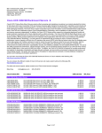
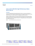
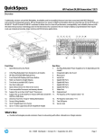
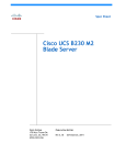
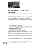
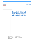
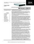
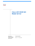
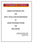
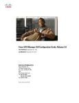
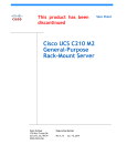
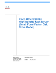
Spec Sheet
Cisco UCS B440 M2
Blade Server
CISCO SYSTEMS
170 WEST TASMAN DR.
SAN JOSE, CA, 95134
WWW.CISCO.COM
PUBLICATION HISTORY
REV A.15
MAY 16, 2013
CONTENTS
OVERVIEW . . . . . . . . . . . . . . . . . . . . . . . . . . . . . . . . . . . . . . . . . . . . . . . 3
DETAILED VIEWS . . . . . . . . . . . . . . . . . . . . . . . . . . . . . . . . . . . . . . . . . . . 4
Chassis Front View . . . . . . . . . . . . . . . . . . . . . . . . . . . . . . . . . . . . . . . . . . . . . . . . . . .4
BASE SERVER STANDARD CAPABILITIES and FEATURES . . . . . . . . . . . . . . . . . 5
CONFIGURING the SERVER . . . . . . . . . . . . . . . . . . . . . . . . . . . . . . . . . . . . 6
STEP
STEP
STEP
STEP
STEP
STEP
STEP
STEP
STEP
ORDER
1 VERIFY BASE SKU . . . . . . . . . . . . . . . . . . . . . . . . . . . . . . . . . . . . . . . . . . . . . . 7
2 CHOOSE CPU(S) . . . . . . . . . . . . . . . . . . . . . . . . . . . . . . . . . . . . . . . . . . . . . . 8
3 CHOOSE MEMORY . . . . . . . . . . . . . . . . . . . . . . . . . . . . . . . . . . . . . . . . . . . . . 9
4 CHOOSE HARD DISK DRIVES or SOLID-STATE DRIVES . . . . . . . . . . . . . . . . . . . . . . 13
5 CHOOSE RAID CONFIGURATION . . . . . . . . . . . . . . . . . . . . . . . . . . . . . . . . . . . 14
6 CHOOSE MEZZANINE OPTION CARD(S) . . . . . . . . . . . . . . . . . . . . . . . . . . . . . . . 15
7 CHOOSE OPERATING SYSTEM AND VALUE-ADDED SOFTWARE . . . . . . . . . . . . . . . . 16
8 CHOOSE OPERATING SYSTEM MEDIA KIT . . . . . . . . . . . . . . . . . . . . . . . . . . . . . . 19
9 CHOOSE SERVICE and SUPPORT LEVEL . . . . . . . . . . . . . . . . . . . . . . . . . . . . . . 20
OPTIONAL KVM CABLE . . . . . . . . . . . . . . . . . . . . . . . . . . . . . . . . . . . . . . . . . . . 25
SUPPLEMENTAL MATERIAL . . . . . . . . . . . . . . . . . . . . . . . . . . . . . . . . . . . 26
Motherboard . . . . . . . . . . . . . . . . . . . . . . . . . . . . . . . . . . . . . . . . . . . . . . . . . . . . . . 26
DIMM and CPU Layout . . . . . . . . . . . . . . . . . . . . . . . . . . . . . . . . . . . . . . . . . . . . . . . . 27
Memory Population Recommendations . . . . . . . . . . . . . . . . . . . . . . . . . . . . . . . . . 27
TECHNICAL SPECIFICATIONS . . . . . . . . . . . . . . . . . . . . . . . . . . . . . . . . . . 29
Dimensions and Weight . . . . . . . . . . . . . . . . . . . . . . . . . . . . . . . . . . . . . . . . . . . . . . . 29
Power Specifications . . . . . . . . . . . . . . . . . . . . . . . . . . . . . . . . . . . . . . . . . . . . . . . . 29
Cisco UCS B440 M2 Blade Server
2
OVERVIEW
OVERVIEW
The Cisco® UCS B440 M2 Blade Server is a four-socket, full-width blade server that combines the
performance of the Intel E7-4800/8800 series processors with up to four small form factor (SFF) hard disk
drives (HDDs) or solid-state drives (SSDs), 32 DIMM slots that support up to 1 terabyte (TB) of memory, and
two dual-port mezzanine card connections for up to 40 Gbps of redundant I/O throughput. The Cisco UCS
B440 M2 server is designed to power the most demanding enterprise applications. The UCS B440 M2 server is
shown in Figure 1.
Figure 1
Cisco UCS B440 M2 Blade Server
Cisco UCS B440 M2 Blade Server
3
DETAILED VIEWS
DETAILED VIEWS
Chassis Front View
Figure 2 shows the front of the Cisco UCS B440 M2 Blade Server.
Figure 2
Chassis Front View
1
Hard drive bay 1
9
Right ejector thumbscrew
2
Hard drive bay 2
10
Power button and LED
3
Hard drive bay 3
11
Network link status LED
4
Hard drive bay 4
12
Blade health LED
5
RAID battery backup module (BBU)
13
Local console connection1
6
Left ejector thumbscrew
14
Reset button access
7
Left ejector handle
15
Beaconing button and LED
8
Right ejector handle
Notes . . .
1. For more information regarding the KVM cable connection, see ORDER OPTIONAL KVM CABLE on
page 25
4
Cisco UCS B440 M2 Blade Server
BASE SERVER STANDARD CAPABILITIES and FEATURES
BASE SERVER STANDARD CAPABILITIES and FEATURES
Table 1 lists the capabilities and features of the base server. Details about how to configure the server for
a particular feature or capability (for example, number of processors, disk drives, or amount of memory)
are provided in CONFIGURING the SERVER on page 6.
Table 1 Capabilities and Features
Capability/Feature
Description
Chassis
The B440 M2 Blade Server mounts in a Cisco UCS 5100-series chassis
CPU
Either 2 or 4 Intel® Xeon® E7-4800 or E7-8800 series processors
Chipset
Intel® 7510 chipset
Memory
32 slots for registered DIMMs, up to 1 TB.
Expansion slots
Two dual-port mezzanine slots are provided
Storage controller
LSI SAS2108 6G SAS RAID controller
■
RAID 0 and 1
■
RAID 5 and 6 are optionally available through a license key upgrade
■
Battery backup unit for 1 GB write cache is optionally available
Internal storage devices
Up to four optional front-accessible, hot-swappable hard disk drives (HDDs)
or solid-state drives (SSDs).
Video
The server CIMC chip includes a Matrox G200 core. The first 8 MB of memory
are allocated to the video core.
Interfaces
One front-accessible console connector (see ORDER OPTIONAL KVM CABLE
on page 25)
Power subsystem
Integrated in the Cisco UCS 5100 series chassis
Fans
Integrated in the Cisco UCS 5100 series chassis
Integrated management
processor
The built-in Cisco Integrated Management Controller (CIMC) GUI or CLI
interface enables you to monitor the server inventory, health, and system
event logs.
Cisco UCS B440 M2 Blade Server
5
CONFIGURING the SERVER
CONFIGURING the SERVER
Follow these steps to configure the Cisco UCS B440 M2 Server:
6
■
STEP 1 VERIFY BASE SKU, page 7
■
STEP 2 CHOOSE CPU(S), page 8
■
STEP 3 CHOOSE MEMORY, page 9
■
STEP 4 CHOOSE HARD DISK DRIVES or SOLID-STATE DRIVES, page 13
■
STEP 6 CHOOSE MEZZANINE OPTION CARD(S), page 15
■
STEP 7 CHOOSE OPERATING SYSTEM AND VALUE-ADDED SOFTWARE, page 16
■
STEP 8 CHOOSE OPERATING SYSTEM MEDIA KIT, page 19
■
STEP 9 CHOOSE SERVICE and SUPPORT LEVEL, page 20
Cisco UCS B440 M2 Blade Server
CONFIGURING the SERVER
STEP 1
VERIFY BASE SKU
Verify the product ID (PID) of the base server as shown in Table 2.
Table 2 PID of the Base B440 M2 Server
Product ID (PID)
B440-BASE-M2
Description
UCS B440 M2 Blade Server w/o CPU, memory, HDD, mezzanine
The B440-BASE-M2 base server:
■
Does not include CPUs, memory DIMMs, SSDs, HDDs, or mezzanine cards.
NOTE: Use the steps on the following pages to configure the server with
the components that you want to include.
Cisco UCS B440 M2 Blade Server
7
CONFIGURING the SERVER
STEP 2
CHOOSE CPU(S)
The standard CPU features are:
■
Intel Xeon E7-4800 or E7-8800 series CPUs
■
Intel 7510 chipset
■
Cache size of 18, 24, or 30 MB
Choose CPUs
The available CPUs are listed in Table 3.
Table 3 Available CPUs: Intel Xeon E7-48xx/8867L Family
Product ID (PID)
Intel
Number
Clock
Freq
(GHz)
Power
(W)
Cache
Size (MB)
Cores
QPI
Highest DDR3
DIMM Clock
Support (MHz)
UCS-CPU-E78867L
E7-8867L
2.13
105
30
10
6.40
13331
UCS-CPU-E78837
E7-8837
2.66
130
24
8
6.40
13331
UCS-CPU-E74870
E7-4870
2.40
130
30
10
6.40
13331
UCS-CPU-E74860
E7-4860
2.26
130
24
10
6.40
13331
UCS-CPU-E74850
E7-4850
2.00
130
24
10
6.40
13331
UCS-CPU-E74830
E7-4830
2.13
105
24
8
6.40
13331
UCS-CPU-E74807
E7-4807
1.86
95
18
6
4.80
13332
Notes . . .
1. Maximum operational speed = 1066 MHz
2. Maximum operational speed = 800 MHz
Approved Configurations
(1) Two-CPU Configuration
■
Choose two identical CPUs from any one row in Table 3.
(2) Four-CPU Configuration
■
Choose four identical CPUs from any one row in Table 3.
Caveats
■
8
You must choose either two identical CPUs or four identical CPUs.
Cisco UCS B440 M2 Blade Server
CONFIGURING the SERVER
STEP 3
CHOOSE MEMORY
The standard memory features are:
■
DIMMs
—
Maximum memory bandwidth: 800 MHz for E7-4807, 1066 MHz for all other CPUs
—
Ranks per DIMM: 2 or 4
—
Operational voltage: 1.5 or 1.35 V
—
Registered DIMM (RDIMM)
—
Mirroring option
—
Advanced error correcting code (ECC)
—
Double device data correction (DDDC)
NOTE: DDDC support applies to x4 DIMMs only.
■
Each CPU controls four DDR3 channels. Each of the channels controls a matched pair of
DIMMs. The maximum number of DIMMs that can be installed per CPU is 8 (4 DIMM kits). See
Figure 3.
NOTE: Memory mirroring is supported and settable using the UCSM Service Profile
“Memory RAS Configuration” setting.
Cisco UCS B440 M2 Blade Server
9
CONFIGURING the SERVER
Figure 3
10
B440 M2 Memory Organization
Cisco UCS B440 M2 Blade Server
CONFIGURING the SERVER
Select DIMMs
DIMMs are available as two-DIMM kits. Each of the product IDs in Table 4 specifies two DIMMs.
Table 4 Available DDR3 DIMMs
Product ID (PID)
PID Description
Voltage
Ranks/
DIMM
DIMM Pair Kit Options (2 DIMMs per kit)
UCS-MR-2X041RX-C
2x4GB DDR3 1333-MHz RDIMM/PC3-10600/1R/x4/1.35v
1.5/1.35 V
1
UCS-MR-2X082RX-C
2x8GB DDR3 1333-MHz RDIMM/PC3-10600/2R/x4/1.35v
1.5/1.35 V
2
UCS-MR-2X164RX-D
2x16GB NHS DDR3-1333-MHz RDIMM/PC3-10600/4R/x4/1.35v
1.5/1.35 V
4
UCS-MR-2X324RX-C
2x32GB DDR3 1333-MHz RDIMM/PC3-10600/4R/x4/1.35V
1.5/1.35 V
4
Approved Configurations
(1) 2-CPU Configuration
■
16 DIMMs capacity total
■
Select one, two, or four DIMM kits (2, 4, or 8 DIMMs) per CPU. The DIMMs for each CPU will
be placed by the factory as shown in Table 5.
Table 5 DIMM Placement
Number of DIMMs
DIMM Placement in Numbered/Colored DIMM Slots
(see Figure 6 on page 27)
2
(A0, A1) - blue slots
4
(A0, A1) - blue slots; (C0, C1) - white slots
8
(A0, A1) - blue slots; (C0, C1) - white slots
(B0, B1) - yellow slots; (D0, D1) - black slots
(2) 4-CPU Configuration
■
32 DIMMs capacity total
■
Select one, two, or four DIMM kits (2, 4, or 8 DIMMs) per CPU. The DIMMs for each CPU will
be placed by the factory as shown in Table 5.
Caveats
■
This server does not support odd numbers of DIMMs in a channel, or a configuration of 6
DIMMs per CPU. There are only three supported DIMM configurations. The DIMMs are sold in
Cisco UCS B440 M2 Blade Server
11
CONFIGURING the SERVER
matched pairs, which must be installed in pairs shown in Table 5 on page 11. Switching out
one of the DIMMs within the matched pair will lead to memory errors.
12
■
The B440 M2 server needs at least one DIMM pair installed for each CPU.
■
DIMMs sold as kits are matched pairs and must remain together when installed in a particular
pair of same-colored (blue, white, yellow, or black) pairs of slots.
■
The DIMMs installed in slots for an absent CPU are not recognized.
■
Memory DIMMs should be installed evenly across the installed CPUs, though it is not a
requirement.
■
Mixing DIMM speeds will cause the faster DIMMs to run at the speed of the slower DIMMs.
■
Your selected CPU(s) can have some affect on performance. The CPUs must be of the same
type.
Cisco UCS B440 M2 Blade Server
CONFIGURING the SERVER
STEP 4
CHOOSE HARD DISK DRIVES or SOLID-STATE DRIVES
The standard disk drive features are:
■
Small form factor HDDs or SSDs
■
Hot-pluggable
■
Sled-mounted
Choose Drives
The available drives are listed in Table 6.
Table 6 Available Hot-Pluggable Sled-Mounted HDDs or SSDs
PID Description
Drive
Type
Capacity
A03-D146GC2
146 GB 6 Gb SAS 15K RPM SFF HDD
SAS
146 GB
A03-D300GA2
300 GB 6 Gb SAS 10K RPM SFF HDD
SAS
300 GB
UCS-HDD300GI2F105
300 GB 6 Gb SAS 15K RPM SFF HDD
SAS
300 GB
A03-D600GA2
600 GB 6 Gb SAS 10K RPM SFF HDD
SAS
600 GB
UCS-HDD900GI2F106
900 GB 6 Gb SAS 10K RPM SFF HDD
SAS
900 GB
UCS-SD400G0KA2-G
400GB SATA 2.5" Enterprise Value SSD
SATA
400 GB
UCS-SD300G0KA2-E
300 GB SATA SFF SSD
SATA
300 GB
UCS-SD200G0KA2-E
200 GB SATA SFF SSD
SATA
200 GB
UCS-SD100G0KA2-G
100GB SATA 2.5" Enterprise Value SSD
SATA
100 GB
UCS-SSD100GI1F104
100 GB SATA SFF SSD (STEC)
SATA
100 GB
Product ID (PID)
HDDs
SSDs
Approved Configurations
(1) Zero to Four Drives
■
Select from 0 to 4 drives from Table 6.
Caveats
■
You can mix SAS/SATA drives, but not HDD/SSD drives. See STEP 5 CHOOSE RAID
CONFIGURATION, page 14 for available RAID configurations.
■
You cannot mix HDDs and SSDs.
Cisco UCS B440 M2 Blade Server
13
CONFIGURING the SERVER
STEP 5
CHOOSE RAID CONFIGURATION
The B440 M2 server integrates the LSI SAS2108 6G SAS RAID controller.
Choose RAID Options
If desired, choose the RAID 5, 6 upgrade option and battery backup option listed in Table 7. The
BBU is an intelligent battery backup unit that protects disk write cache data during a power loss
on the RAID controller for up to 72 hours. We recommend that you replace the BBU once per
year or after 1,000 recharge cycles, whichever comes first.
Table 7 Available RAID Options
Product ID (PID)
PID Description
RAID Battery Backup Option
N20-LBBU
Battery backup unit for 1 GB write cache
RAID Configuration
N20-BRAID-K1
RAID upgrade supporting RAID 5 and 6
Caveats
14
■
No RAID option will be effective if you have a mix of SAS and SATA drives.
■
No RAID option is possible if you have no drives.
■
You must have at least one drive installed in order to add an optional battery backup unit.
Cisco UCS B440 M2 Blade Server
CONFIGURING the SERVER
STEP 6
CHOOSE MEZZANINE OPTION CARD(S)
The standard PCIe card offerings are:
■
Converged Network Adapters (CNA)
■
Network Interface Cards (NICs)
Choose a PCIe Option Card
The available PCIe option cards are listed in Table 8.
Table 8 Available PCIe Option Cards
Product ID (PID)
PID Description
Converged Network Adapters (CNA)
N20-AQ0102
Cisco UCS CNA M72KR-Q Qlogic Adapter
N20-AE01022
Cisco UCS CNA M72KR-E Emulex Adapter
UCS-VIC-M82-8P
Cisco UCS VIC 1280 dual 40Gb capable Virtual Interface Card
Network Interface Cards (NICs)
N20-AB00021
Cisco UCS M51KR-B Broadcom 57711 Adapter
Notes . . .
1. A quantity of 0, 1, or 2 N20-AB0002 cards can be selected
Approved Configurations
(1) Select at least one PCIe Mezzanine Cards (mandatory)
You must select at least one card and may select up to two cards.
NOTE: The server must be running UCS Manager v1.3 (N10-MGT005) or later to
support two adapter cards.
To help ensure that your operating system is compatible with the cards you have selected,
please check the Hardware Compatibility List at this URL:
http://www.cisco.com/en/US/products/ps10477/prod_technical_reference_list.html
Cisco UCS B440 M2 Blade Server
15
CONFIGURING the SERVER
STEP 7
CHOOSE OPERATING SYSTEM AND VALUE-ADDED SOFTWARE
Several operating systems and value-added software programs are available. Select as desired
from Table 9.
Table 9 OSs and Value-Added Software (for 4-CPU servers)
PID Description
Product ID (PID)
Microsoft Windows Server
MSWS-08R2-STHV
Windows Svr 2008 ST media R2 ST (1-4CPU, 5CAL)
MSWS-08R2-ENHV
Windows Svr 2008 EN media R2 EN (1-8CPU, 25CAL)
MSWS-08R2-DCHV2S
Windows Svr 2008 R2-2 CPU-Data Center
MSWS-12-ST2S
Windows Server 2012 Standard (2 CPU/2 VMs)
MSWS-12-DC2S
Windows Server 2012 Datacenter (2 CPU/Unlimited VMs)
MSWS-12-ST2S-NS
Windows Server 2012 Standard (2 CPU/2 VMs) No Cisco SVC
MSWS-12-DC2S-NS
Windows Server 2012 Datacenter (2 CPU/Unlim VM) No Cisco Svc
SUSE Linux Enterprise Server
SLES-1A
SLES/1yr subscription/svcs required/0 media
SLES-3A
SLES/3yr subscription/svcs required/0 media
UCS-SLES-TERMS
Acceptance of Terms, Standalone SLES License for UCS Servers Red Hat Enterprise Linux
RHEL-2S-1G-1A
RHEL/2 Socket/1 Guest/1Yr Svcs Required
RHEL-2S-1G-3A
RHEL/2 Socket/1 Guest/3Yr Svcs Required
RHEL-2S-4G-1A
RHEL/2 Socket/4 Guest/1Yr Svcs Required
RHEL-2S-4G-3A
RHEL/2 Socket/4 Guest/3Yr Svcs Required
RHEL-2S-UG-1A
RHEL/2 Socket/U Guest/1Yr Svcs Required
RHEL-2S-UG-3A
RHEL/2 Socket/U Guest/3Yr Svcs Required
RHEL-4S-1G-1A
RHEL/4 Socket/1 Guest/1Yr Svcs Required RHEL-4S-1G-3A
RHEL/4 Socket/1 Guest/3Yr Svcs Required RHEL-4S-4G-1A
RHEL/4 Socket/4 Guest/1Yr Svcs Required RHEL-4S-4G-3A
RHEL/4 Socket/4 Guest/3Yr Svcs Required RHEL-4S-UG-1A
RHEL/4 Socket/U Guest/1Yr Svcs Required RHEL-4S-UG-3A
RHEL/4 Socket/U Guest/3Yr Svcs Required RHEL-HA-2S-1A
RHEL Option/High-Availability/2 Socket/1Yr Svcs Required RHEL-HA-2S-3A
RHEL Option/High-Availability/2 Socket/3Yr Svcs Required 16
Cisco UCS B440 M2 Blade Server
CONFIGURING the SERVER
Table 9 OSs and Value-Added Software (for 4-CPU servers) (continued)
PID Description
Product ID (PID)
RHEL-HA-4S-1A
RHEL Option/High-Availability/4 Socket/1Yr Svcs Required RHEL-HA-4S-3A
RHEL Option/High-Availability/4 Socket/3Yr Svcs Required RHEL-RS-2S-1A
RHEL Option/Resilient Storage w/HA /2 Socket/1 Yr Svcs Reqd RHEL-RS-2S-3A
RHEL Option/Resilient Storage w/HA /2 Socket/3 Yr Svcs Reqd RHEL-RS-4S-1A
RHEL Option/Resilient Storage w/HA /4 Socket/1 Yr Svcs Reqd RHEL-RS-4S-3A
RHEL Option/Resilient Storage w/HA /4 Socket/3 Yr Svcs Reqd RHEL-SFS-2S-1A
RHEL Option/Scalable File System/2 Socket/1 Yr Svcs Required RHEL-SFS-2S-3A
RHEL Option/Scalable File System/2 Socket/1 Yr Svcs Required
RHEL-SFS-4S-1A
RHEL Option/Scalable File System/4 Socket/1 Yr Svcs Required RHEL-SFS-4S-3A
RHEL Option/Scalable File System/4 Socket/3 Yr Svcs Required BMC
BMC-002
BMC BladeLogic CM, Physical Server BMC-012
BMC BPPM Per Server BMC-SE-4C
BMC BladeLogic Standard Edition, 4 Cores, Support Required
BMC-SE-6C
BMC BladeLogic Standard Edition, 6 Cores, Support Required
BMC-SE-8C
BMC BladeLogic Standard Edition, 8 Cores, Support Required
BMC-SE-10C
BMC BladeLogic Standard Edition, 10 Cores, Support Required
BMC-AE-4C
BMC BladeLogic Advanced Edition, 4 Cores, Support Required
BMC-AE-6C
BMC BladeLogic Advanced Edition, 6 Cores, Support Required
BMC-AE-8C
BMC BladeLogic Advanced Edition, 8 Cores, Support Required
BMC-AE-10C
BMC BladeLogic Standard Edition, 10 Cores, Support Required
UCS-BMC-TERMS
Acceptance of Terms, Standalone BMC License for UCS Servers VMWare 5
VMW-VS5-STD-1A
VMware vSphere 5 Standard for 1 Processor, 1 Year, Support Rqd
VMW-VS5-STD-2A
VMware vSphere 5 Standard for 1 Processor, 2 Year, Support Rqd
VMW-VS5-STD-3A
VMware vSphere 5 Standard for 1 Processor, 3 Year, Support Rqd
VMW-VS5-STD-4A
VMware vSphere 5 Standard for 1 Processor, 4 Year, Support Rqd
VMW-VS5-STD-5A
VMware vSphere 5 Standard for 1 Processor, 5 Year, Support Rqd
VMW-VS5-ENT-1A
VMware vSphere 5 Enterprise for 1 Processor, 1 Year Support Rqd
VMW-VS5-ENT-2A
VMware vSphere 5 Enterprise for 1 CPU, 2 Yr Support Rqd
VMW-VS5-ENT-3A
VMware vSphere 5 Enterprise for 1 CPU, 3 Yr Support Rqd
VMW-VS5-ENT-4A
VMware vSphere 5 Enterprise for 1 Processor, 4 Year Support Rqd
Cisco UCS B440 M2 Blade Server
17
CONFIGURING the SERVER
Table 9 OSs and Value-Added Software (for 4-CPU servers) (continued)
PID Description
Product ID (PID)
VMW-VS5-ENT-5A
VMware vSphere 5 Enterprise for 1 CPU, 5 Yr Support Rqd
VMW-VS5-ENTP-1A
VMware vSphere 5 Enterprise Plus for 1 Processor, 1 Year Support Rqd
VMW-VS5-ENTP-2A
VMware vSphere 5 Enterprise Plus for 1 CPU, 2 Yr Support Rqd
VMW-VS5-ENTP-3A
VMware vSphere 5 Enterprise Plus for 1 Processor, 3 Year Support Rqd
VMW-VS5-ENTP-4A
VMware vSphere 5 Enterprise Plus for 1 Processor, 4 Year Support Rqd
VMW-VS5-ENTP-5A
VMware vSphere 5 Enterprise Plus for 1 Processor, 5 Year Support Rqd
VMW-VC5-STD-1A
VMware vCenter 5 Server Standard, 1 yr support required VMW-VC5-STD-2A
VMware vCenter 5 Server Standard, 2 yr support required VMW-VC5-STD-3A
VMware vCenter 5 Server Standard, 3 yr support required VMW-VC5-STD-4A
VMware vCenter 5 Server Standard, 4 yr support required VMW-VC5-STD-5A
VMware vCenter 5 Server Standard, 5 yr support required UCS-VMW-TERMS
Acceptance of Terms, Standalone VMW License for UCS Servers 18
Cisco UCS B440 M2 Blade Server
CONFIGURING the SERVER
STEP 8
CHOOSE OPERATING SYSTEM MEDIA KIT
Choose the optional operating system media listed in Table 10.
Table 10
OS Media
Product ID (PID)
PID Description
RHEL-6
RHEL 6 Recovery Media Only (Multilingual)
SLES-11
SLES 11 media only (multilingual)
MSWS-08R2-STHV-RM
Windows Svr 2008 R2 ST (1-4CPU, 5CAL), Media
MSWS-08RS-ENHV-RM
Windows Svr 2008 R2 EN (1-8CPU, 25CAL), Media
MSWS-08R2-DCHV-RM
Windows Svr 2008 R2 DC (1-8CPU, 25CAL), Media
MSWS-12-ST2S-RM
Windows Server 2012 Standard (2 CPU/2 VMs) Recovery Media
MSWS-12-DC2S-RM
Windows Server 2012 Datacenter (2 CPU/Unlimited VM) Rec Media
Cisco UCS B440 M2 Blade Server
19
CONFIGURING the SERVER
STEP 9
CHOOSE SERVICE and SUPPORT LEVEL
A variety of service options are available, as described in this section.
Unified Computing Warranty, No Contract
If you have noncritical implementations and choose to have no service contract, the following
coverage is supplied:
■
Three-year parts coverage.
■
Next business day (NBD) onsite parts replacement eight hours a day, five days a week.
■
90-day software warranty on media.
■
Ongoing downloads of BIOS, drivers, and firmware updates.
■
UCSM updates for systems with Unified Computing System Manager. These updates include
minor enhancements and bug fixes that are designed to maintain the compliance of UCSM
with published specifications, release notes, and industry standards.
SMARTnet for UCS
For support of the entire Unified Computing System, Cisco offers the Cisco SMARTnet for UCS
Service. This service provides expert software and hardware support to help sustain
performance and high availability of the unified computing environment. Access to Cisco
Technical Assistance Center (TAC) is provided around the clock, from anywhere in the world.
For UCS blade servers, there is Smart Call Home, which provides proactive, embedded
diagnostics and real-time alerts. For systems that include Unified Computing System Manager,
the support service includes downloads of UCSM upgrades. The Cisco SMARTnet for UCS Service
includes flexible hardware replacement options, including replacement in as little as two hours.
There is also access to Cisco's extensive online technical resources to help maintain optimal
efficiency and uptime of the unified computing environment. You can choose a desired service
listed in Table 11.
Table 11
20
Cisco SMARTnet for UCS Service
Product ID (PID)
On Site?
Description
CON-PREM-B440M2
Yes
ONSITE 24X7X2 UCS B440 M2 Blade Server
CON-OSP-B440M2
Yes
ONSITE 24X7X4 UCS B440 M2 Blade Server
CON-OSE-B440M2
Yes
ONSITE 8X5X4 UCS B440 M2 Blade Server
CON-OS-B440M2
Yes
ONSITE 8X5XNBD UCS B440 M2 Blade Server
CON-S2P-B440M2
No
SMARTNET 24X7X2 UCS B440 M2 Blade Server
CON-SNTP-B440M2
No
SMARTNET 24X7X4 UCS B440 M2 Blade Server
CON-SNTE-B440M2
No
SMARTNET 8X5X4 UCS B440 M2 Blade Server
CON-SNT-B440M2
No
SMARTNET 8X5XNBD UCS B440 M2 Blade Server
Cisco UCS B440 M2 Blade Server
CONFIGURING the SERVER
SMARTnet for UCS Hardware Only Service
For faster parts replacement than is provided with the standard Cisco Unified Computing System
warranty, Cisco offers the Cisco SMARTnet for UCS Hardware Only Service. You can choose from
two levels of advanced onsite parts replacement coverage in as little as four hours. SMARTnet
for UCS Hardware Only Service provides remote access any time to Cisco support professionals
who can determine if a return materials authorization (RMA) is required. You can choose a
service listed in Table 12.
Table 12
SMARTnet for UCS Hardware Only Service
Product ID (PID)
Service
Level GSP
On
Site?
Description
CON-UCW7-B440M2
UCW7
Yes
UC PLUS 24X7X4OS UCS B440 M2 Blade Server
CON-UCW5-B440M2
UCW5
Yes
UC PLUS 8X5XNBDOS UCS B440 M2 Blade Server
Unified Computing Partner Support Service
Cisco Partner Support Service (PSS) is a Cisco Collaborative Services service offering that is
designed for partners to deliver their own branded support and managed services to enterprise
customers. Cisco PSS provides partners with access to Cisco's support infrastructure and assets
to help them:
■
Expand their service portfolios to support the most complex network environments
■
Lower delivery costs
■
Deliver services that increase customer loyalty
Partner Unified Computing Support Options enable eligible Cisco partners to develop and
consistently deliver high-value technical support that capitalizes on Cisco intellectual assets.
This helps partners to realize higher margins and expand their practice.
PSS is available to all Cisco PSS partners, but requires additional specializations and
requirements. For additional information, see the following URL:
www.cisco.com/go/partnerucssupport
The two Partner Unified Computing Support Options include:
■
Partner Support Service for UCS
■
Partner Support Service for UCS Hardware Only
Cisco UCS B440 M2 Blade Server
21
CONFIGURING the SERVER
Partner Support Service for UCS provides hardware and software support, including triage
support for third party software, backed by Cisco technical resources and level three support.
See Table 13.
Table 13
Partner Support Service for UCS
Product ID (PID)
Service
Level
GSP
On
Site?
Description
CON-PSJ1-B440M2
PSJ1
No
UCS SUPP PSS 8X5XNBD UCS B440 M2 Blade Server
CON-PSJ2-B440M2
PSJ2
No
UCS SUPP PSS 8X5X4 UCS B440 M2 Blade Server
CON-PSJ3-B440M2
PSJ3
No
UCS SUPP PSS 24X7X4 UCS B440 M2 Blade Server
CON-PSJ4-B440M2
PSJ4
No
UCS SUPP PSS 24X7X2 UCS B440 M2 Blade Server
Partner Support Service for UCS Hardware Only provides customers with replacement parts in as
little as two hours. See Table 14.
Table 14
Partner Support Service for UCS (Hardware Only)
Product ID (PID)
Service
Level
GSP
On
Site?
Description
CON-PSW2-B440M2
PSW2
No
UCS W PL PSS 8X5X4 UCS B440 M2 Blade Server
CON-PSW3-B440M2
PSW3
No
UCS W PL PSS 24X7X4 UCS B440 M2 Blade Server
CON-PSW4-B440M2
PSW4
No
UCS W PL PSS 24X7X2 UCS B440 M2 Blade Server
Unified Computing Combined Support Service
Combined Services makes it easier to purchase and manage required services under one
contract. SMARTnet services for UCS help increase the availability of your vital data center
infrastructure and realize the most value from your unified computing investment. The more
benefits you realize from the Cisco Unified Computing System (Cisco UCS), the more important
the technology becomes to your business. These services allow you to:
22
■
Optimize the uptime, performance, and efficiency of your UCS
■
Protect your vital business applications by rapidly identifying and addressing issues
■
Strengthen in-house expertise through knowledge transfer and mentoring
■
Improve operational efficiency by allowing UCS experts to augment your internal staff
resources
■
Enhance business agility by diagnosing potential issues before they affect your operations
Cisco UCS B440 M2 Blade Server
CONFIGURING the SERVER
You can choose a service listed in Table 15.
Table 15
UCS Computing Combined Support Service
Product ID (PID)
Service
Level
GSP
On
Site?
Description
CON-NCF2-B440M2
NCF2
No
CMB SPT SVC 24X7X2 UCS B440 M2 Blade Server
CON-NCF2P-B440M2
NCF2P
Yes
CMB SPT SVC 24X7X2OS UCS B440 M2 Blade Server
CON-NCF4P-B440M2
NCF4P
Yes
CMB SPT SVC 24X7X4OS UCS B440 M2 Blade Server
CON-NCF4S-B440M2
NCF4S
Yes
CMB SPT SVC 8X5X4OS UCS B440 M2 Blade Server
CON-NCFCS-B440M2
NCFCS
Yes
CMB SPT SVC 8X5XNBDOS UCS B440 M2 Blade Server
CON-NCFE-B440M2
NCFE
No
CMB SPT SVC 8X5X4 UCS B440 M2 Blade Server
CON-NCFP-B440M2
NCFP
No
CMB SPT SVC 24X7X4 UCS B440 M2 Blade Server
CON-NCFT-B440M2
NCFT
No
CMB SPT SVC 8X5XNBD UCS B440 M2 Blade Server
Unified Computing Drive Retention Service
With the Cisco Unified Computing Drive Retention (UCDR) Service, you can obtain a new disk
drive in exchange for a faulty drive without returning the faulty drive. In exchange for a Cisco
replacement drive, you provide a signed Certificate of Destruction (CoD) confirming that the
drive has been removed from the system listed, is no longer in service, and has been destroyed.
Sophisticated data recovery techniques have made classified, proprietary, and confidential
information vulnerable, even on malfunctioning disk drives. The UCDR service enables you to
retain your drives and ensures that the sensitive data on those drives is not compromised, which
reduces the risk of any potential liabilities. This service also enables you to comply with
regulatory, local, and federal requirements.
If your company has a need to control confidential, classified, sensitive, or proprietary data, you
might want to consider one of the Drive Retention Services listed in Table 16.
NOTE: Cisco does not offer a certified drive destruction service as part of this
service.
Cisco UCS B440 M2 Blade Server
23
CONFIGURING the SERVER
Table 16 Drive Retention Service Options
Service Description
Service
Program Name
SMARTnet for UCS
Service with Drive
Retention
UCS DR
SMARTnet for UCS
HW ONLY+Drive
Retention
UCS HW+DR
Service
Level GSP
Service Level
Product ID (PID)
UCSD7
24x7x4 Onsite
CON-UCSD7-B440M2
UCSD7
8x5xNBD Onsite
CON-UCSD5-B440M2
UCWD7
24x7x4 Onsite
CON-UCWD7-B440M2
UCWD5
8x5xNBD Onsite
CON-UCWD5-B440M2
For more service and support information, see the following URL:
http://www.cisco.com/en/US/services/ps2961/ps10312/Unified_Computing_Services_Overview.pdf
For a complete listing of available services for Cisco Unified Computing System, see this URL:
http://www.cisco.com/en/US/products/ps10312/serv_group_home.html
24
Cisco UCS B440 M2 Blade Server
CONFIGURING the SERVER
ORDER OPTIONAL KVM CABLE
The KVM cable provides a connection into the server, providing a DB9 serial connector, a VGA connector for
a monitor, and dual USB 2.0 ports for a keyboard and mouse. With this cable, you can create a direct
connection to the operating system and the BIOS running on the server.
The KVM cable ordering information is listed in Table 17.
Table 17 KVM Cable
Product ID (PID)
PID Description
37-1016-01
KVM Cable
Figure 4
KVM Cable
1
Connector (to server front panel)
3
VGA connector (for a monitor)
2
DB-9 serial connector
4
Two-port USB 2.0 connector (for a mouse and
keyboard)
Cisco UCS B440 M2 Blade Server
25
SUPPLEMENTAL MATERIAL
SUPPLEMENTAL MATERIAL
Motherboard
A top view of the B440 M2 motherboard is shown in Figure 5.
Figure 5
26
B440 M2 Motherboard
Cisco UCS B440 M2 Blade Server
SUPPLEMENTAL MATERIAL
DIMM and CPU Layout
Each CPU controls four memory channels, as follows (refer to Figure 3 on page 10):
■
Channels A, B, C, and D
—
Bank 0: A0 (blue DIMM slot), C0 (white DIMM slot), B0 (yellow DIMM slot), D0 (black
DIMM slot)
—
Bank 1: A1 (blue DIMM slot), C1 (white DIMM slot), B1 (yellow DIMM slot), D1 (black
DIMM slot)
The DIMM and CPU physical layout is shown in Figure 6. Each CPU is located to the right of the DIMMs it
controls.
Figure 6
DIMM and CPU Layout
NOTE: DIMMs installed in slots for an absent CPU are not recognized.
Memory Population Recommendations
See Table 5 on page 11. Note that DIMMs in slots of the same color must be electrically paired with each
other, and should be populated with identically matched DIMMs that were ordered as a pair. Do not swap a
paired DIMM with a DIMM that is not identical in manufacturer part number.
When considering the memory configuration of your server, you should observe the following:
■
There is only one DIMM slot (one bank) in each of the DDR channels. Therefore, all DIMM
pairs in a B440 M2 server must be identical.
■
Your selected CPU(s) can have some effect on performance. All CPUs in the server must be
of the same type.
■
Performance degradation can result from the following:
—
Mixing DIMM sizes and densities within a pair is not allowed and both DIMMs in the
pair will be logically removed from the memory array
Cisco UCS B440 M2 Blade Server
27
SUPPLEMENTAL MATERIAL
28
—
Unevenly populating DIMMs between CPUs
—
Populating channels with an odd number of total ranks (for example, mixing
single-rank and dual-rank DIMMs)
—
Using anything other than 16 or 32 DIMMs properly placed in the system
Cisco UCS B440 M2 Blade Server
TECHNICAL SPECIFICATIONS
TECHNICAL SPECIFICATIONS
Dimensions and Weight
Table 18 UCS B200 M2 Dimensions and Weight1
Parameter
Value
Height
1.95 in. (50 mm)
Width
16.50 in.(419.1 mm)
Depth
24.4 in. (620 mm)
Weight
34.5 lbs (15.65 kg)*
Notes . . .
1. The system weight given here is an estimate for a fully configured system and will vary depending on the
number of CPUs, memory DIMMs, and other optional items.
Power Specifications
For configuration-specific power specifications, use the Cisco UCS Power Calculator at:
http://www.cisco.com/assets/cdc_content_elements/flash/dataCenter/cisco_ucs_power_calculator/.
Cisco UCS B440 M2 Blade Server
29
TECHNICAL SPECIFICATIONS
30
Cisco UCS B440 M2 Blade Server