1
SUPER
SUPERSERVER
7047R-TRF
USER'S MANUAL
Revision 1.0a
®
The information in this User’s Manual has been carefully reviewed and is believed to be accurate.
The vendor assumes no responsibility for any inaccuracies that may be contained in this document,
makes no commitment to update or to keep current the information in this manual, or to notify any
person or organization of the updates. Please Note: For the most up-to-date version of this
manual, please see our web site at www.supermicro.com.
Super Micro Computer, Inc. ("Supermicro") reserves the right to make changes to the product
described in this manual at any time and without notice. This product, including software and
documentation, is the property of Supermicro and/or its licensors, and is supplied only under a
license. Any use or reproduction of this product is not allowed, except as expressly permitted by
the terms of said license.
IN NO EVENT WILL SUPERMICRO BE LIABLE FOR DIRECT, INDIRECT, SPECIAL, INCIDENTAL,
SPECULATIVE OR CONSEQUENTIAL DAMAGES ARISING FROM THE USE OR INABILITY TO
USE THIS PRODUCT OR DOCUMENTATION, EVEN IF ADVISED OF THE POSSIBILITY OF
SUCH DAMAGES. IN PARTICULAR, SUPERMICRO SHALL NOT HAVE LIABILITY FOR ANY
HARDWARE, SOFTWARE, OR DATA STORED OR USED WITH THE PRODUCT, INCLUDING THE
COSTS OF REPAIRING, REPLACING, INTEGRATING, INSTALLING OR RECOVERING SUCH
HARDWARE, SOFTWARE, OR DATA.
Any disputes arising between manufacturer and customer shall be governed by the laws of Santa
Clara County in the State of California, USA. The State of California, County of Santa Clara shall
be the exclusive venue for the resolution of any such disputes. Super Micro's total liability for all
claims will not exceed the price paid for the hardware product.
FCC Statement: This equipment has been tested and found to comply with the limits for a Class
A digital device pursuant to Part 15 of the FCC Rules. These limits are designed to provide
reasonable protection against harmful interference when the equipment is operated in a commercial
environment. This equipment generates, uses, and can radiate radio frequency energy and, if not
installed and used in accordance with the manufacturer’s instruction manual, may cause harmful
interference with radio communications. Operation of this equipment in a residential area is likely
to cause harmful interference, in which case you will be required to correct the interference at your
own expense.
California Best Management Practices Regulations for Perchlorate Materials: This Perchlorate
warning applies only to products containing CR (Manganese Dioxide) Lithium coin cells. “Perchlorate
Material-special handling may apply. See www.dtsc.ca.gov/hazardouswaste/perchlorate”
WARNING: Handling of lead solder materials used in this
product may expose you to lead, a chemical known to
the State of California to cause birth defects and other
reproductive harm.
Manual Revision 1.0a
Release Date: February 21, 2012
Unless you request and receive written permission from Super Micro Computer, Inc., you may not
copy any part of this document.
Information in this document is subject to change without notice. Other products and companies
referred to herein are trademarks or registered trademarks of their respective companies or mark
holders.
Copyright © 2012 by Super Micro Computer, Inc.
All rights reserved.
Printed in the United States of America
Preface
Preface
About This Manual
This manual is written for professional system integrators and PC technicians. It
provides information for the installation and use of the SUPERSERVER 7047R-TRF.
Installation and maintainance should be performed by experienced technicians only.
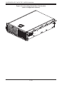
The SUPERSERVER 7047R-TRF is a high-end server based on the SC745TS-920NBP
4U tower/rackmountable chassis and the X9DRi-F serverboard.
Manual Organization
Chapter 1: Introduction
The first chapter provides a checklist of the main components included with the
server system and describes the main features of the X9DRi-F serverboard and
the SC745TS-920NBP chassis.
Chapter 2: Server Installation
This chapter describes the steps necessary to install the A+ Server 7047R-TRF into
a rack and check out the server configuration prior to powering up the system. If
your server was ordered without processor and memory components, this chapter
will refer you to the appropriate sections of the manual for their installation.
Chapter 3: System Interface
Refer here for details on the system interface, which includes the functions and
information provided by the control panel on the chassis as well as other LEDs
located throughout the system.
Chapter 4: System Safety
You should thoroughly familiarize yourself with this chapter for a general overview
of safety precautions that should be followed when installing and servicing the A+
Server 7047R-TRF.
Chapter 5: Advanced Serverboard Setup
Chapter 5 provides detailed information on the X9DRi-F serverboard, including the
locations and functions of connections, headers and jumpers. Refer to this chapter
when adding or removing processors or main memory and when reconfiguring the
serverboard.
iii
SUPERSERVER 7047R-TRF USER'S MANUAL
Chapter 6: Advanced Chassis Setup
Refer to Chapter 6 for detailed information on the SC745TS-920NBP server chassis.
You should follow the procedures given in this chapter when installing, removing
or reconfiguring SAS/SATA or peripheral drives and when replacing system power
supply units and cooling fans.
Chapter 7: BIOS
The BIOS chapter includes an introduction to BIOS and provides detailed information
on running the CMOS Setup Utility.
Appendix A: BIOS POST Error Codes
Appendix B: Installing Windows
Appendix C: System Specifications
iv
Preface
Notes
v
SUPERSERVER 7047R-TRF USER'S MANUAL
Table of Contents
Chapter 1 Introduction
1-1
Overview ......................................................................................................... 1-1
1-2
Serverboard Features ..................................................................................... 1-2
Processors ...................................................................................................... 1-2
Memory ........................................................................................................... 1-2
Serial ATA ....................................................................................................... 1-2
Onboard Controllers/Ports .............................................................................. 1-2
Graphics Controller ......................................................................................... 1-2
Other Features ................................................................................................ 1-3
1-3
Server Chassis Features ................................................................................ 1-3
System Power ................................................................................................. 1-3
Front Control Panel ......................................................................................... 1-3
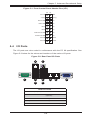
I/O Backplane.................................................................................................. 1-3
Cooling System ............................................................................................... 1-3
1-4
Advanced Power Management (for -F Models Only) ..................................... 1-4
Intel® Intelligent Power Node Manager (NM) ................................................. 1-4
Manageability Engine (ME) ............................................................................. 1-4
1-4
Contacting Supermicro .................................................................................... 1-6
Chapter 2 Server Installation
2-1
Overview ......................................................................................................... 2-1
2-2
Unpacking the System .................................................................................... 2-1
2-3
Preparing for Setup ......................................................................................... 2-1
Choosing a Setup Location ............................................................................. 2-2
Rack Precautions ............................................................................................ 2-2
Server Precautions.......................................................................................... 2-2
Warnings and Precautions! ........................................................................................ 2-2
Rack Mounting Considerations ....................................................................... 2-3
Ambient Operating Temperature ................................................................ 2-3
Reduced Airflow ......................................................................................... 2-3
Mechanical Loading ................................................................................... 2-3
Circuit Overloading ..................................................................................... 2-3
Reliable Ground ......................................................................................... 2-3
2-4
Installing the System into a Rack ................................................................... 2-4
Identifying the Sections of the Rack Rails ..................................................... 2-4
Installing the Chassis Rails ............................................................................. 2-5
Installing the Rack Rails ................................................................................. 2-6
vi
Table of Contents
Installing the Server into the Rack .................................................................. 2-7
2-5
Checking the Serverboard Setup .................................................................... 2-8
2-6
Checking the Drive Bay Setup ........................................................................ 2-9
Chapter 3 System Interface
3-1
Overview ......................................................................................................... 3-1
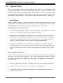
3-2
Control Panel Buttons ..................................................................................... 3-1
Power .............................................................................................................. 3-1
Reset ............................................................................................................... 3-1
3-3
Control Panel LEDs ........................................................................................ 3-2
Power .............................................................................................................. 3-2
HDD................................................................................................................. 3-2
NIC1 ................................................................................................................ 3-2
NIC2 ................................................................................................................ 3-2
Overheat/Fan Fail ........................................................................................... 3-2
Power Fail ....................................................................................................... 3-3
3-4
Drive Carrier LEDs ......................................................................................... 3-3
Chapter 4 System Safety
4-1
Electrical Safety Precautions .......................................................................... 4-1
4-2
General Safety Precautions ............................................................................ 4-2
4-3
ESD Precautions ............................................................................................. 4-3
4-4
Operating Precautions .................................................................................... 4-4
Chapter 5 Advanced Serverboard Setup
5-1
Handling the Serverboard ............................................................................... 5-1
Precautions ..................................................................................................... 5-1
Unpacking ....................................................................................................... 5-1
5-2
Processor and Heatsink Installation................................................................ 5-2
Installing a Passive CPU Heatsink ................................................................. 5-6
Removing the Heatsink ................................................................................... 5-7
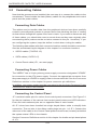
5-3
Connecting Cables .......................................................................................... 5-8
Connecting Data Cables ................................................................................. 5-8
Connecting Power Cables .............................................................................. 5-8
Connecting the Control Panel ......................................................................... 5-8
5-4
I/O Ports .......................................................................................................... 5-9
5-5
Installing Memory .......................................................................................... 5-10
Memory Support ............................................................................................ 5-10
DIMM Module Population Configuration .................................................. 5-12
5-6
Adding PCI Expansion Cards ....................................................................... 5-13
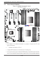
5-7
Serverboard Details ...................................................................................... 5-14
vii
SUPERSERVER 7047R-TRF USER'S MANUAL
H8DGU(-F) Quick Reference ........................................................................ 5-15
5-8
Connector Definitions ................................................................................... 5-16
5-9
Jumper Settings ............................................................................................ 5-24
5-10
Onboard Indicators........................................................................................ 5-26
5-11
SATA Drive Connections ............................................................................... 5-27
5-13
Installing Drivers............................................................................................ 5-28
Explanation of Jumpers ................................................................................ 5-24
Supero Doctor III ........................................................................................... 5-29
Chapter 6 Advanced Chassis Setup
6-1
Static-Sensitive Devices .................................................................................. 6-1
6-2
Front Control Panel ......................................................................................... 6-3
6-3
System Fans ................................................................................................... 6-4
6-4
Drive Bay Installation ...................................................................................... 6-6
Precautions ..................................................................................................... 6-1
Fan Failure ...................................................................................................... 6-4
SAS/SATA Drives ............................................................................................ 6-6
SAS/SATA Backplane...................................................................................... 6-7
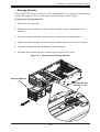
Storage Module ............................................................................................... 6-9
6-5
Power Supply ................................................................................................ 6-10
Power Supply Failure .................................................................................... 6-10
Chapter 7 BIOS
7-1
Introduction...................................................................................................... 7-1
7-2
Main Menu ...................................................................................................... 7-1
7-3
Advanced Settings Menu ................................................................................ 7-2
7-4
Event Logs .................................................................................................... 7-21
7-5
IPMI ............................................................................................................... 7-22
7-6
Boot ............................................................................................................... 7-24
7-7
Security ......................................................................................................... 7-24
7-8
Save & Exit ................................................................................................... 7-25
Starting the Setup Utility ................................................................................. 7-1
System Time/System Date ............................................................................. 7-2
Appendix A BIOS POST Error Codes
Appendix B System Specifications
Drive Bays ....................................................................................................... B-1
Peripheral Drive Bays ..................................................................................... B-1
Expansion Slots .............................................................................................. B-1
Serverboard..................................................................................................... B-2
viii
Chapter 1: Introduction
Chapter 1
Introduction
1-1
Overview
The SUPERSERVER 7047R-TRF is a high-end server comprised of two main
subsystems: the SC745TS-920NBP 4U/tower chassis and the X9DRi-F serverboard.
Please refer to our web site for information on operating systems that have been
certified for use with the system (www.supermicro.com).
In addition to the serverboard and chassis, various hardware components have
been included with the 7047R-TRF, as listed below:
•
Two (2) passive CPU heatsinks (SNK-P0048PS)
•
Three (3) 8-cm system fans (FAN-0074L4)
•
Two (2) 8-cm rear exhaust fans (FAN-0082L4)
•
One (1) air shroud (MCP-310-49001-0N)
•
One (1) 20" front control 16-to-16 pin ribbon cable (CBL-0087)
•
Four (4) 200 mm 4-to-4 Pin Middle Fan Power Extension cables (CBL-0216L)
•
SAS Accessories
One (1) SAS backplane (BPN-SAS-743TQ)
Two (2) 40-cm 8-to-8-pin ribbon cable w/tube for SGPIO (CBL-157L)
Six (6) 35-cm SATA cables (CBL-0061L)
Eight (8) 3.5" drive trays (MCP-220-00092-0B)
•
One CD containing drivers and utilities
•
One rackmount kit (Optional: CSE-PT26)
1-1
SUPERSERVER 7047R-TRF USER'S MANUAL
1-2
Serverboard Features
At the heart of the SUPERSERVER 7047R-TRF lies the X9DRi-F, a dual processor
serverboard based on the Intel PCH C602/C606 chipset. Below are the main
features of the X9DRi-F. (See Figure 1-1 for a block diagram of the chipset).
Processors
The X9DRi-F supports single or dual E5-2600 Series processors in Socket R LGA2011
type sockets. Please refer to our web site for a complete listing of supported
processors (www.supermicro.com).
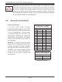
Memory
The X9DRi-F has 16 single/dual/tri/quad channel 240-pin DIMM sockets that can
support up to 512 GB of DDR3 1600/1333/1066/800 MHz registered ECC SDRAM in
two-channel memory bus. Memory sizes of 1GB, 2GB, 4GB, 8GB, 16GB and 32GB
@ 1.35V/1.5V voltages are supported. Please refer to Chapter 5 for installing
memory.
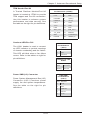
Serial ATA
An on-chip (PCH C606) SATA controller is integrated into theX9DRi-F to provide
a six-port, 3 Gb/sec SATA subsystem, which is RAID 0, 1, 5 and 10 supported.
The SATA drives are hot-swappable units.
Note: You must have RAID set up to enable the hot-swap capability of the SATA
drives. Documentation on RAID setup guidelines can be found on our web site.
Onboard Controllers/Ports
The color-coded I/O ports on the X9DRi-F include two COM ports (one header and
one port), a VGA (monitor) port, eleven USB 2.0 ports (4x rear, 6x header, 1x type
A), PS/2 mouse and keyboard ports, two gigabit Ethernet ports and one dedicated
IPMI LAN port.
Note 1: For more information on IPMI configuration, please refer to the IPMI User's
Guide posted on our website at http://www.supermicro.com/support/manuals/
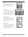
Graphics Controller
The X9DRi-F features an integrated Nuvoton WP450R BMC Base-board Controller
(BMC) chip, which also acts as a video controller..
1-2
Chapter 1: Introduction
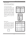
Other Features
Other onboard features that promote system health include onboard voltage
monitors, auto-switching voltage regulators, chassis and CPU overheat sensors,
power management, AC power loss recovery, virus protection and BIOS rescue.
1-3
Server Chassis Features
The following is a general outline of the main features of the SC745TS-920NBP
server chassis.
System Power
The SC745TS-920NBP features a single 920 Watt power supply. Power must be
removed from the server before replacing a failed power supply unless a second
(optional) 920 Watt power module is installed to provide the system with redundant
power.
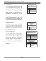
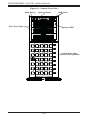
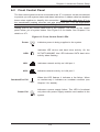
Front Control Panel
The control panel on the SUPERSERVER 7047R-TRF provides you with system
monitoring and control. LEDs indicate system power, HDD activity, network activity,
system overheat and power supply failure. A main power button and a system reset
button are also included. In addition, two USB ports have been incorporated into
the control panel to provide front side USB access.
I/O Backplane
The SC745TS-920NBP is an extended ATX form factor chassis that may be used in
either a tower or a 4U rackmount configuration. The I/O backplane provides seven
tool-less motherboard expansion slots, one COM port, one parallel port, one VGA
port, two USB 2.0 ports, PS/2 mouse and keyboard ports, two gigabit Ethernet ports
and a dedicated IPMI LAN port.
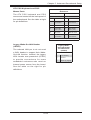
Cooling System
The chassis has an innovative cooling design that includes three 8-cm hot-plug
system cooling fans located in the middle section of the chassis as well as two 8-cm
hot-plug exhaust fans located at the rear of the chassis. An air shroud channels the
airflow from the system fans to efficiently cool the processor area of the system.
The power supply module also includes a cooling fan.
1-3
SUPERSERVER 7047R-TRF USER'S MANUAL
1-4
Advanced Power Management (for -F Models Only)
Intel® Intelligent Power Node Manager (NM)
The Intel® Intelligent Power Node Manager (IPNM) provides your system with
real-time thermal control and power management for maximum energy efficiency.
Although IPNM Specification Version 1.5 is supported by the BMC (Baseboard
Management Controller), your system must also have IPNM-compatible
Manageability Engine (ME) firmware installed to use this feature.
Manageability Engine (ME)
The Manageability Engine, which is an ARC controller embedded in the IOH (I/O
Hub), provides Server Platform Services (SPS) to your system. The services
provided by SPS are different from those proveded by the ME on client platforms.
1-4
Chapter 1: Introduction
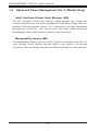
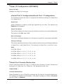
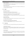
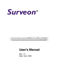
Figure 1-1. Intel PCH C602/C606 Chipset:
System Block Diagram
Note: This is a general block diagram. Please see Chapter 5 for details.
#1
DMI2
#2 #3
PCI-E X16 G3
PCI-E X16 G3
PCI-E X4
PCI-E X4 G3
PCI-E X8 G3
QPI
8GB/s
SAS
DMI2
LANE1/2/3/4
PCI-E X8
SLOT 5
LAN
82580
DMI2 4GB/s
SLOT 1
PCI-E X8
PCI-E X8 G3
PCI-E X16 G3
DDR3
800/1066/1333
P0
QPI
8G
E5-2600 Series
Processor
8 SNB CORE
DDR3
SLOT 4
P1
P1
#2 #3A #3B #1B DMI2 #1A
PCI-E X8 G3
SAS
Ports 0~3
SAS
Ports 4~7
LANE5
3.0 Gb/S
6.0 Gb/S
FOR PORT 0/1
BMC
VGA
SATA
#0~#6
PCH C602/C606
LANE6
PCI-32
USB 2.0
USB
#0~#8
SLOT 3
PCI-E X8
QPI
8G
PCI-E X16
8 SNB CORE
DDR3
DDR3
800/1066/1333
SLOT 2
PCI-E X16
E5-2600 Series
P0
Processor
PCI-E X16
SLOT 6
#1-6
#1-5
#1-4
#1-3
#1-2
#1-1
#0-6
#0-5
#0-4
#0-3
#0-2
#0-1
SPI
MS
KB
1 Type-A
2 Rear
4 Front
SIO
W83527
COM1
External
1-5
COM2
Header
SUPERSERVER 7047R-TRF USER'S MANUAL
1-4
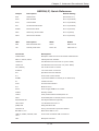
Contacting Supermicro
Headquarters
Address:
Super Micro Computer, Inc.
980 Rock Ave.
San Jose, CA 95131 U.S.A.
Tel:
+1 (408) 503-8000
Fax:
+1 (408) 503-8008
Email:
[email protected] (General Information)
[email protected] (Technical Support)
Web Site:
www.supermicro.com
Europe
Address:
Super Micro Computer B.V.
Het Sterrenbeeld 28, 5215 ML
's-Hertogenbosch, The Netherlands
Tel:
+31 (0) 73-6400390
Fax:
+31 (0) 73-6416525
Email:
[email protected] (General Information)
[email protected] (Technical Support)
[email protected] (Customer Support)
Asia-Pacific
Address:
Super Micro Computer, Inc.
4F, No. 232-1, Liancheng Rd.
Chung-Ho 235, Taipei County
Taiwan, R.O.C.
Tel:
+886-(2) 8226-3990
Fax:
+886-(2) 8226-3991
Web Site:
www.supermicro.com.tw
Technical Support:
Email:
[email protected]
Tel:
+886-(2) 8226-5990
1-6
Chapter 2: Server Installation
Chapter 2
Server Installation
2-1
Overview
This chapter provides a quick setup checklist to get your A+ Server 7047R-TRF up
and running. Following these steps in the order given should enable you to have
the system operational within a minimum amount of time. This quick setup assumes
that your system has come to you with the processors and memory preinstalled. If
your system is not already fully integrated with a serverboard, processors, system
memory etc., please turn to the chapter or section noted in each step for details on
installing specific components.
The 7047R-TRF may be employed either as a tower or mounted in a rack as a 4U
rackmount chassis. If using it as a tower unit, please read the Server Precautions
in the next section and then skip ahead to Section 2-5.
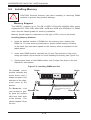
2-2
Unpacking the System
You should inspect the box the system was shipped in and note if it was damaged
in any way. If the server itself shows damage you should file a damage claim with
the carrier who delivered it.
Decide on a suitable location for the A+ Server 7047R-TRF. It should be situated
in a clean, dust-free area that is well ventilated. Avoid areas where heat, electrical
noise and electromagnetic fields are generated. You will also need it placed near
a grounded power outlet. Be sure to read the Rack and Server Precautions in the
next section.
2-3
Preparing for Setup
The box the system was shipped in may include two sets of rail assemblies, two
rail mounting brackets and mounting screws needed for installing the system into a
rack (optional kit). Follow the steps in the order given to complete the installation
process in a minimum amount of time. Please read this section in its entirety before
you begin the installation procedure outlined in the sections that follow.
2-1
SUPERSERVER 7047R-TRF USER'S MANUAL
Choosing a Setup Location
•
•
Leave enough clearance in front of the rack to enable you to open the front door
completely (~25 inches) and approximately 30 inches of clearance in the back
of the rack to allow for sufficient airflow and ease in servicing.
This product is not suitable for use with visual display work place devices
acccording to §2 of the the German Ordinance for Work with Visual Display
Units.
!
Warnings and Precautions!
!
Rack Precautions
•
•
•
•
•
Ensure that the leveling jacks on the bottom of the rack are fully extended to
the floor with the full weight of the rack resting on them.
In single rack installation, stabilizers should be attached to the rack. In multiple
rack installations, the racks should be coupled together.
Always make sure the rack is stable before extending a component from the
rack.
You should extend only one component at a time - extending two or more simultaneously may cause the rack to become unstable.
Slide/rail-mounted equipment is not to be used as a shelf or workspace.
Server Precautions
•
•
•
•
Review the electrical and general safety precautions in Chapter 4.
Determine the placement of each component in the rack before you install the
rails.
Install the heaviest server components on the bottom of the rack first, and then
work up.
Use a regulating uninterruptible power supply (UPS) to protect the server from
power surges, voltage spikes and to keep your system operating in case of a
power failure.
2-2
Chapter 2: Server Installation
•
•
Allow the hot plug SATA drives and power supply modules to cool before touching them.
Always keep the rack's front door and all panels and components on the servers
closed when not servicing to maintain proper cooling.
Rack Mounting Considerations
Ambient Operating Temperature
If installed in a closed or multi-unit rack assembly, the ambient operating
temperature of the rack environment may be greater than the ambient temperature
of the room. Therefore, consideration should be given to installing the equipment
in an environment compatible with the manufacturer’s maximum rated ambient
temperature (Tmra).
Reduced Airflow
Equipment should be mounted into a rack so that the amount of airflow required
for safe operation is not compromised.
Mechanical Loading
Equipment should be mounted into a rack so that a hazardous condition does not
arise due to uneven mechanical loading.
Circuit Overloading
Consideration should be given to the connection of the equipment to the power
supply circuitry and the effect that any possible overloading of circuits might have
on overcurrent protection and power supply wiring. Appropriate consideration of
equipment nameplate ratings should be used when addressing this concern.
Reliable Ground
A reliable ground must be maintained at all times. To ensure this, the rack
itself should be grounded. Particular attention should be given to power supply
connections other than the direct connections to the branch circuit (i.e. the use of
power strips, etc.).
2-3
SUPERSERVER 7047R-TRF USER'S MANUAL
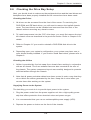
2-4
Installing the System into a Rack
This section provides information on installing the system into a rack unit. Rack
installation requires the use of the optional rackmount kit. If the system has already
been mounted into a rack or if you are using it as a tower, you can skip ahead to
Sections 2-5 and 2-6.
There are a variety of rack units on the market, which may mean the assembly
procedure will differ slightly. The following is a guideline for installing the server into
a rack with the rack rails provided in the rackmount kit. You should also refer to the
installation instructions that came with the rack unit you are using.
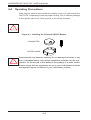
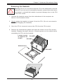
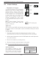
Identifying the Sections of the Rack Rails
The optional rackmount kit includes two rack rail assemblies. Each of these
assemblies consist of three sections: an inner fixed chassis rail that secures to
the chassis, an outer rack rail that secures directly to the rack itself and two rail
brackets, which also attack to the rack (see Figure 2-1.) The inner and outer rails
must be detached from each other to install.
To remove the inner chassis rail, pull it out as far as possible - you should hear a
"click" sound as a locking tab emerges from inside the rail assembly and locks the
inner rail. Depress the locking tab to pull the inner rail completely out. Do this for
both assemblies (one for each side).
Figure 2-1. Identifying the Sections of the Rack Rails
Outer Rail
Inner Rail
Rail Brackets
2-4
Chapter 2: Server Installation
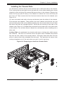
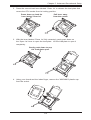
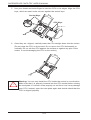
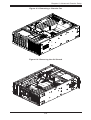
Installing the Chassis Rails
You will need to remove the top cover and the feet to add rack rails to the chassis.
First, remove the top and right covers (top and left covers when standing as a tower
chassis) by first removing the screws that secure them to the chassis. Depress the
button on the top (side if tower) of the chassis to release the cover and then pull
the cover off. Then unscrew the four feet and remove them from the chassis (see
Figure 2-2).
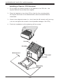
You can now attach rack rails to the top and bottom (now the sides) of the chassis.
First add the rack handles. Then position the inner chassis rail sections you just
removed along the side of the chassis making sure the screw holes line up. Note
that these two rails are left/right specific. Screw the rail securely to the side of the
chassis (see Figure 2-3). Repeat this procedure for the other rail on the other side
of the chassis. You will also need to attach the rail brackets when installing into a
telco rack.
Locking Tabs: As mentioned, the chassis rails have a locking tab, which serves
two functions. The first is to lock the server into place when installed and pushed
fully into the rack, wh