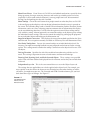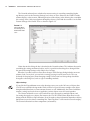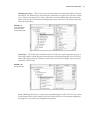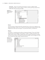
1
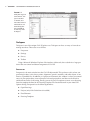
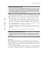
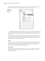
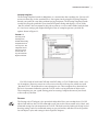
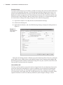
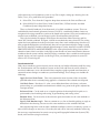
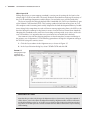
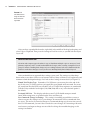
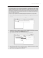
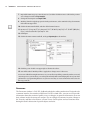
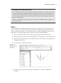
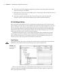
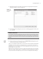
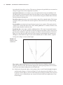
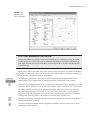
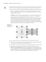
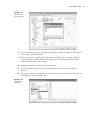
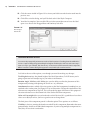
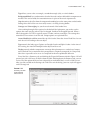
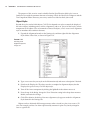
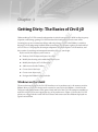
Chapter 1 AL Getting Dirty: The Basics of Civil 3D MA TE RI Understanding Civil 3D’s controls and operation is critical to mastering it. With its dizzying array of options and settings, getting Civil 3D to look and feel comfortable can take some effort. Learning how to use its numerous dialogs and tool palettes, as well as the Ribbon, is critical to driving Civil 3D and getting feedback about your design. This chapter explores the look and feel of Civil 3D as a CAD program, the unique components that make up the Civil 3D interface, and the creation of a working environment that matches the way you design. By the end of this chapter, you’ll learn to: •u Find any Civil 3D object with just a few clicks D •u Modify the drawing scale and default object layers TE •u Modify the display of Civil 3D tooltips •u Add a new tool to the Toolbox GH •u Create a basic label style •u Create a new object style RI •u Navigate the Ribbon’s contextual tabs PY Windows on the Model CO The most obvious change to the Civil 3D interface over its predecessors is the context-sensitive Ribbon. Many of Civil 3D’s design tools can now be accessed via the Ribbon. A facelift to the Toolspace and enhancements to the general look and feel of the Civil 3D workspace combine to make this release easier to navigate than any of its predecessors. Figure 1.1 shows the Civil 3D palette sets along with the AutoCAD Tool Palettes and context-sensitive Ribbon displayed in a typical environment. 2 | Chapter 1 Getting Dirty: The Basics of Civil 3D Figure 1.1 Civil 3D in a typical environment. Toolspace is docked on the left, and Panorama and Tool Palettes float over the drawing window. The Ribbon is at the top of the workspace. Toolspace Toolspace is one of the unique Civil 3D palette sets. Toolspace can have as many as four tabs to manage user data. These tabs are as follows: •u Prospector •u Settings •u Survey •u Toolbox Using a Microsoft Windows Explorer–like interface within each, these tabs drive a large portion of the user control and data management of Civil 3D. Prospector Prospector is the main window into the Civil 3D object model. This palette or tab is where you go mining for data; it also shows points, alignments, parcels, corridors, and other objects as one concise, expandable list. In addition, in a project environment, this window is where you control access to your project data, create references to shared project data, and observe the check-in and check-out status of a drawing. Finally, you can also use Prospector to create a new drawing from the templates defined in the Drawing Template File Location branch in your AutoCAD Options dialog. Prospector has the following branches: •u Open Drawings •u Projects (only if the Vault client is installed) •u Data Shortcuts •u Drawing Templates | Windows on the Model 3 Master and Active Drawing Views If you can’t see the Projects or Drawing Templates branch in Figure 1.1, look at the top of the Prospector pane. There is a drop-down menu for operating in Active Drawing View or Master View mode. Selecting Active Drawing View displays only the active drawing and Data Shortcuts. Master View mode, however, displays the Projects, the Drawing Templates, and the Data Shortcuts, as well as the branches of all drawings that are currently open. In addition to the branches, Prospector has a series of icons across the top that toggle various settings on and off. Some of the Civil 3D icons from previous versions have been removed, and their functionality has been universally enabled for Civil 3D 2011. Those icons are noted here. Item Preview Toggle Turns on and off the display of the Toolspace item preview within Prospector. These previews can be helpful when you’re navigating drawings in projects (you can select one to check out) or when you’re attempting to locate a parcel on the basis of its visual shape. In general, however, you can turn off this toggle—it’s purely a user preference. Preview Area Display Toggle When Toolspace is undocked, this button moves the Preview Area from the right of the tree view to beneath the tree view area. Panorama Display Toggle Turns on and off the display of the Panorama window (which is discussed in a bit). To be honest, there doesn’t seem to be a point to this button, but it’s here nonetheless. Help This should be obvious, but it’s amazing how many people overlook it. Have You Looked in the Help File Lately? The AutoCAD Civil 3D development team in Manchester, New Hampshire, has worked hard to make the Help files in Civil 3D top notch and user friendly. The Help files should be your first line of support! Open Drawings This branch of Prospector contains the drawings currently open in Civil 3D. Each drawing is subdivided into groups by major object type, such as points, point groups, surfaces, and so forth. These object groups then allow you to view all the objects in the collection. Some of these groups are empty until objects are created. You can learn details about an individual object by expanding the tree and selecting an object. Within each drawing, the breakdown is similar. If a collection isn’t empty, a plus sign appears next to it, as in a typical Windows Explorer interface. Selecting any of these top-level collection names displays a list of members in the preview area. Right-clicking the collection name allows 4 | Chapter 1 Getting Dirty: The Basics of Civil 3D you to select various commands that apply to all the members of that collection. For example, right-clicking the Point Groups collection brings up the menu shown in Figure 1.2. Figure 1.2 Context-sensitive menus in Prospector In addition, right-clicking the individual object in the list view offers many commands unique to Civil 3D: Zoom to Object and Pan to Object are typically included. By using these commands, you can find any parcel, point, cross section, or other Civil 3D object in your drawing almost instantly. Many longtime users of AutoCAD have resisted right-clicking menus for their daily tasks since AutoCAD 14. In other AutoCAD products this may be possible, but in Civil 3D you’ll miss half the commands! This book focuses on the specific options and commands for each object type during discussions of the particular objects. Projects The Projects branch of Prospector is the starting point for real team collaboration. This branch allows you to sign in and out of Vault, review what projects are available, manage the projects you sort through for information, check out drawings for editing, and review the status of drawings as well as that of individual project-based objects. Data Shortcuts Simply put, a data shortcut identifies the path to a specific object, in a specific drawing. Many users have found data shortcuts to be ideal in terms of project collaboration for two reasons: flexibility and simplicity. | Windows on the Model 5 Drawing Templates The Drawing Templates branch is added more as a convenience than anything else. You can still create new drawings via the standard File New option, but by using the Drawing Templates branch, you can do the same thing without leaving Prospector. The Drawing Templates branch searches the file path specified in your AutoCAD Options dialog and displays a list of all the .dwt files it finds. You can customize this path to point to a server or other folder, but by default it’s a local user-settings path. Right-clicking the name of a template presents you with the options shown in Figure 1.3. Figure 1.3 Creating a new drawing from within the Drawing Templates branch of Prospector. The templates shown here are located in the folder set in your AutoCAD Options window. Civil 3D is built on both AutoCAD and AutoCAD Map, so Civil 3D 2011 comes with a variety of templates. However, most users will want to select one of the top few, which start with _Autodesk Civil 3D and then have some descriptive text. These templates have been built on the basis of customer feedback to provide Civil 3D with a varying collection of object styles. These templates give you a good starting point for creating a template that meets your needs or the needs of your firm. Settings The Settings tab of Toolspace is the proverbial rabbit hole. Here you can adjust how Civil 3D objects look and how the Civil 3D commands work. You use this tab to control styles, labels, and command settings for each component of Civil 3D. This book starts by looking at the top level of drawing settings and a few command settings to get you familiar, and then covers the specifics for each object’s styles and settings in their respective chapters. 6 | Chapter 1 Getting Dirty: The Basics of Civil 3D Drawing Settings Starting at the drawing level, Civil 3D has a number of settings that you must understand before you can use the program efficiently. Civil 3D understands that the end goal of most users is to prepare construction documents on paper. To that end, most labeling and display settings are displayed in inches for imperial users and millimeters for metric users instead of nominal units like many other AutoCAD objects. Because much of this is based on an assumed working scale, let’s look at how to change that setting, along with some other drawing options: 1. Open the file Sample Site.dwg from the installed tutorial drawings. 2. Switch to the Settings tab. 3. Right-click the filename, and select Edit Drawing Settings to display the dialog shown in Figure 1.4. Figure 1.4 The Drawing Settings dialog Each tab in this dialog controls a different aspect of the drawing. Most of the time, you’ll pick up the Object Layers, Abbreviations, and Ambient Settings from a companywide template. But the drawing scale and coordinate information change for every job, so you’ll visit the Units and Zone and the Transformation tabs frequently. Units and Zone Tab The Units and Zone tab lets you specify metric or imperial units for your drawing. You can also specify the conversion factor between systems. In addition, you can control the assumed plotting scale of the drawing. The drawing units typically come from a template, but the options for scaling blocks and setting AutoCAD variables depend on your working environment. Many engineers continue to work in an arbitrary coordinate system using the settings as shown | Windows on the Model 7 earlier, but using a real coordinate system is easy! For example, setting up a drawing for a the Dallas, Texas, area, you’d follow this procedure: 1. Select USA, Texas from the Categories drop-down menu on the Units and Zone tab. 2. Select NAD83 Texas State Planes, North Central Zone, US Foot from the Available Coordinate Systems drop-down menu. There are literally hundreds, if not thousands, of available coordinate systems. These are established by international agreement; because Civil 3D is a worldwide product, almost any recognized surveying coordinate system can be found in the options. Once your coordinate system has been established, you can change it on the Transformation tab if desired. This tab also includes the options Scale Objects Inserted from Other Drawings and Set AutoCAD Variables to Match. In Figure 1.4, both are unchecked to move forward. The scaling option has been problematic in the past because many firms work with drawings that have no units assigned and therefore scale incorrectly; but you can experiment with this setting as you’d like. The Set AutoCAD Variables to Match option attempts to set the AutoCAD variables AUNITS, DIMUNITS, INSUNITS, and MEASUREMENT to the values placed in this dialog. You can learn about the nature of these variables via the Help system. Because of some inconsistencies between coordinate-based systems and the AutoCAD engine, sometimes these variables must be approximated. Again, you won’t typically set this flag to True; you should experiment in your own office to see if it can help you. Transformation Tab With a base coordinate system selected, you can now do any further refinement you’d like using the Transformation tab. The coordinate systems on the Units and Zone tab can be refined to meet local ordinances, tie in with historical data, complete a grid to ground transformation, or account for minor changes in coordinate system methodology. These changes can include the following: Apply Sea Level Scale Factor Takes into account the mean elevation of the site and the spheroid radius that is currently being applied as a function of the selected zone ellipsoid. Grid Scale Factor Based on a 1:1 value, a user-defined uniform scale factor, a reference point scaling, or a prismoidal transformation in which every point in the grid is adjusted by a unique amount. Reference Point Can be used to set a singular point in the drawing field via pick or via point number, local northing and easting, or grid northing and easting values. Rotation Point Can be used to set the reference point for rotation via the same methods as the Reference Point. Specify Grid Rotation Angle Enter an amount or set a line to North by picking an angle or deflection in the drawing. You can use this same method to set the azimuth if desired. Most engineering firms work on either a defined coordinate system or an arbitrary system, so none of these changes are necessary. Given that, this tab will be your only method of achieving the necessary transformation for certain surveying and Geographic Information System (GIS)– based, and Land Surveying–based tasks. 8 | Chapter 1 Getting Dirty: The Basics of Civil 3D Object Layers Tab Setting object layers to your company standard is a major part of creating the feel you’re after when using Civil 3D in your office. The nearly 50 objects described here make up the entirety of the Civil 3D modeling components and the objects you and other users will deal with daily. The layers listed in this dialog by default reflect a modified AIA CAD Layer Guideline as part of the National CAD Standard (NCS). This layering standard is built into many places in Civil 3D’s templates and is becoming more widely adopted in the land-development industry. In addition to being fairly comprehensive and well known among engineering firms, the NCS has the benefit of being the roadmap for the future in terms of out-of-the-box content from Autodesk. Adopting this standard means you’ll have fewer things to change with every release of the software. Nevertheless, it is important that every user know how to modify these defaults. One common issue with the shipping templates is that the templates assume road design is the primary use of alignments. Use the following procedure to change the Alignment setting to the NCS for laying out a sanitary sewer: 1. Click the Layer column in the Alignment row, as shown in Figure 1.5. 2. In the Layer Selection dialog list, select C-SSWR-CNTR and click OK. Figure 1.5 Changing the Layer setting for the Alignment object One Object at a Time Note that this procedure only changes the Alignment object. If you want to change the standard of all the objects, you need to adjust the Alignment Labeling, Alignment Table, Profile, Profile View, Profile View Labeling, and so on. To do this, it’s a good idea to right-click in the grid view and select Copy All. You can then paste the contents of this matrix into Microsoft Excel for easy formatting and reviewing. | Windows on the Model 9 One common question that surrounds the Object Layers tab is the check box at lower left: Immediate and Independent Layer On/Off Control of Display Components. What the heck does that mean? Relax—it’s not as complicated as it sounds. Many objects in Civil 3D are built from underlying components. Take an alignment, for example. It’s built from tangents, curves, spirals, extension lines, and so on. Each of these components can be assigned its own layer—in other words, the lines could be assigned to the LINES layer, curves to the CURVES layer, and so on. When this check box is selected, the component’s layer exerts some control. In the example given, if the alignment is assigned to the ALIGN layer and the box is selected, turning off (not freezing) the LINES layer will make the line components of that alignment disappear. Deselect this control, and the LINES layer’s status won’t have any effect on the visibility of the alignment line components. Finally, it’s important to note that this layer control determines the object’s parent layer at creation. Civil 3D objects can be moved to other layers at any time. Changing this setting doesn’t change any objects already in place in the drawing. Abbreviations Tab One could work for years without noticing the Abbreviations tab. The options on this tab allow you to set the abbreviations Civil 3D uses when labeling items as part of its automated routines. The prebuilt settings are based on user feedback, and many of them are the same as the settings from Land Desktop, the last-generation civil engineering product from Autodesk. Changing an abbreviation is as simple as clicking in the Value field and typing a new one. Notice that the Alignment Geometry Point Entity Data section has a larger set of values and some formulas attached. These are more representative of other label styles, and we’ll visit the label editor a little later in this chapter. There’s Always More to Learn Until December 2006, James was still advising users to add “t.” to their labels to get “Rt.” or “Lt.” in the final label. He’d forgotten that the abbreviations being used were set here! By changing the Left and Right abbreviation from “L” and “R” to “Lt.” and “Rt.”, respectively, you can skip that step in the label setup. Sometimes there are just too many options to remember them all! Ambient Settings Tab The Ambient Settings tab can be daunting at first. The term ambient means “surround” or “surrounding,” and these settings control many of the math, labeling, and display features, as well as the user interaction surrounding the use of Civil 3D. Being familiar with the way this tab works will help you further down the line, because almost every other setting dialog in the program works like the one shown in Figure 1.6. You can approach this tab in the following ways: •u Top to bottom—Expand one branch, handle the settings in that branch, and then close it and move to the next. •u Print and conquer—Expand all the branches using the Expand All Categories button found at the lower right. 10 | Chapter 1 Getting Dirty: The Basics of Civil 3D Figure 1.6 The Ambient Settings tab with the General branch expanded After you have expanded the branches, right-click in the middle of the displayed options and select Copy to Clipboard. Then paste the settings to Excel for review, as you did with the Object Layers tab. Sharing the Workload The Print and Conquer approach makes it easy to distribute multiple copies to surveyors, land planners, engineers, and so on and let them fill in the changes. Then, creating a template for each group is a matter of making their changes. If you’re asking end users who aren’t familiar with the product to make these changes, it’s easy to miss one. Working line by line is fairly foolproof. After you decide how to approach these settings, get to work. The settings are either dropdown menus or text boxes (in the case of numeric entries). Many of them are self-explanatory and common to land-development design. Let’s look at these settings in more detail (see Figure 1.6). Plotted Unit Display Type Remember, Civil 3D knows you want to plot at the end of the day. In this case, it’s asking you how you would like your plotted units measured. For example, would you like that bit of text to be 0.25” tall or ¼” high? Most engineers are comfortable with the Leroy method of text heights (L80, L100, L140, and so on), so the decimal option is the default. Set AutoCAD Units This displays whether or not Civil 3D should attempt to match AutoCAD drawing units, as specified on the Units and Zone tab. Save Command Changes to Settings This setting is incredibly powerful but a secret to almost everyone. By setting it to Yes, your changes to commands will be remembered from use to use. This means if you make changes to a command during use, the next time you call that Civil 3D command, you won’t have to make the same changes. It’s frustrating to do work over because you forgot to change one out of the five things that needed changing, so this setting is invaluable. | Windows on the Model 11 Show Event Viewer Event Viewer is Civil 3D’s main feedback mechanism, especially when things go wrong. It can get annoying, however, and it takes up valuable screen real estate (especially if you’re stuck with one monitor!), so many people turn it off. We recommend leaving it on and pushing it to the side if needed. Show Tooltips One of the cool features that people remark on when they first use Civil 3D is the small pop-up that displays relevant design information when the cursor is paused on the screen. This includes things such as Station-Offset information, Surface Elevation, Section information, and so on. Once a drawing contains numerous bits of information, this display can be overwhelming; therefore, Civil 3D offers the option to turn off these tooltips universally with this setting. A better approach is to control the tooltips at the object type by editing the individual feature settings. You can also control the tooltips by pulling up the properties for any individual object and looking at the Information tab. Imperial to Metric Conversion This displays the conversion method specified on the Units and Zone tab. The two options currently available are US Survey Foot and International Foot. New Entity Tooltip State You can also control tooltips on an individual object level. For instance, you might want tooltip feedback on your proposed surface but not on the existing surface. This setting controls whether the tooltip is turned on at the object level for new Civil 3D objects. Driving Direction Specifies the side of the road that forward-moving vehicles use for travel. This setting is important in terms of curb returns and intersection design. Drawing Unit, Drawing Scale, and Scale Inserted Objects These settings were specified on the Units and Zone tab but are displayed here for reference and so that you can lock them if desired. Independent Layer On This is the same control that was set on the Object Layers tab. The settings that are applied here can also be applied at the object levels. For example, you may typically want elevation to be shown to two decimal places; but when looking at surface elevations, you might want just one. The Override and Child Override columns give you feedback about these types of changes. See Figure 1.7. Figure 1.7 The Child Override indicator in the Elevation values 12 | Chapter 1 Getting Dirty: The Basics of Civil 3D The Override column shows whether the current setting is overriding something higher up. Because you’re at the Drawing Settings level, these are clear. However, the Child Override column displays a down arrow, indicating that one of the objects in the drawing has overridden this setting. After a little investigation through the objects, you’ll find the override is in the Edit Feature Settings of the Profile View as shown in Figure 1.8. Figure 1.8 The Profile Elevation Settings and the Override indicator Notice that in this dialog, the box is checked in the Override column. This indicates that you’re overriding the settings mentioned earlier, and it’s a good alert that things have changed from the general Drawing Settings to this Object Level setting. But what if you don’t want to allow those changes? Each Settings dialog includes one more column: Lock. At any level, you can lock a setting, graying it out for lower levels. This can be handy for keeping users from changing settings at the lower level that perhaps should be changed at a drawing level, such as sign or rounding methods. Object Settings If you click the Expand button next to the drawing name, you see the full array of objects that Civil 3D uses to build its design model. Each of these has special features unique to the object being described, but there are some common features as well. Additionally, the General collection contains settings and styles that are applied to various objects across the entire product. The General collection serves as the catchall for styles that apply to multiple objects and for settings that apply to no objects. For instance, the Civil 3D General Note object doesn’t really belong with the Surface or Pipe collections. It can be used to relate information about those objects, but because it can also relate to something like “Don’t Dig Here!” it falls into the General category. The General collection has three components (or branches): | Windows on the Model 13 Multipurpose Styles These styles are used in many objects to control the display of component objects. The Marker Styles and Link Styles collections are typically used in cross-section views, whereas the Feature Line Styles collection is used in grading and other commands. Figure 1.9 shows the full collection of multipurpose styles and some of the marker styles that ship with the product. Figure 1.9 General multipurpose styles and some marker styles Label Styles The Label Styles collection allows Civil 3D users to place general text notes or label single entities outside the parcel network while still taking advantage of Civil 3D’s flexibility and scaling properties. With the various label styles shown in Figure 1.10, you can get some idea of their usage. Figure 1.10 Line label styles Because building label styles is a critical part of producing plans with Civil 3D, a later section of this chapter looks at how to build a new basic label and some of the common components that appear in every label style throughout the product. 14 | Chapter 1 Getting Dirty: The Basics of Civil 3D Commands Almost every branch in the Settings tree contains a Commands folder. Expanding this folder, as shown in Figure 1.11, shows you the typical long, unspaced command names that refer to the parent object. Figure 1.11 Surface command settings in Toolspace Survey The Survey palette is displayed optionally and controls the use of the survey, equipment, and figure prefix databases. Survey is an essential part of land-development projects. Because of the complex nature of this tab, all of Chapter 3, “Lay of the Land: Survey,” is devoted to it. Toolbox The Toolbox is a launching point for add-ons and reporting functions. To access the Toolbox, from the Home tab in the Ribbon, select Toolspace Palettes Toolbox. Out of the box, the Toolbox contains reports created by Autodesk, but you can expand its functionality to include your own macros or reports. The buttons on the top of the Toolbox, shown in Figure 1.12, allow you to customize the report settings and add new content. Figure 1.12 The Toolbox palette with the Edit Toolbox Content button circled | Windows on the Model 15 A Toolbox Built Just for You You can edit the Toolbox content and the Report Settings by selecting the desired tool, right-clicking, and then executing. Don’t limit yourself to the default reports that ship in the Toolbox, though. Many firms find that adding in-house customizations to the Toolbox gives them better results and is more easily managed at a central level than by customizing via the AutoCAD custom user interface (CUI) and workspace functionality. Let’s add one of the sample Civil 3D Visual Basic Application (VBA) macros to a new Toolbox: 1. Click the Edit Toolbox Content button shown in Figure 1.12 to open the Toolbox Editor in Panorama. 2. Click the button shown here to add a new root category. 3. Click the Root Category1 toolbox that appears. The name will appear in the preview area, where you can edit it. Change the name to Sample Files, and press ↵ . 4. Right-click the Sample Files toolbox, and select New Category as shown here. 5. Expand the Sample Files toolbox to view the new category, and then click the name to edit it in the preview area. Change the name to VBA, and press ↵ . 6. Right-click the VBA category, and select New Tool. 16 | Chapter 1 Getting Dirty: The Basics of Civil 3D 7. Expand the VBA category to view the new tool, and then click the name to edit it in the preview area. Change its name to Pipe Sample. . Change the Description to Sample VBA. 8 9. Working down through the properties in the preview area, select VBA in the drop-down menu in the Execute Type field. 0.Click in the Execute File field, and then click the More button. 1 11.Browse to C:\Program Files\Autocad Civil 3D 2011\Sample\Civil 3D API\COM\Vba\ Pipe\, and select the file PipeSample.dvb. 2.Click Open. 1 13.Click in the Macro Name text field, and type PipeSample as shown here. 4.Click the green check box at upper right to dismiss the editor. 1 15.You will be asked “Would you like to apply those changes now?” Select Yes. You’ve now added that sample VBA macro to your Toolbox. By adding commonly used macros and custom reports to your Toolbox, you can keep them handy without modifying the rest of your Civil 3D interface or programming buttons. It’s just one more way to create an interface and toolset for the way you work. Panorama The Panorama window is Civil 3D’s feedback and tabular editing mechanism. Designed to be a common interface for a number of different Civil 3D–related tasks, you can use it to provide information about the creation of profile views, to edit pipe or structure information, or to run basic volume analysis between two surfaces. For an example of Panorama in action, change to the View tab, and then select Palettes Event Viewer. You’ll explore and use Panorama more during this book’s discussion of specific objects and tasks. | Windows on the Model 17 Running Out of Screen Real Estate? It’s a good idea to turn on Panorama using this technique and then drag it to the side so you always see any new information. Although it’s possible to turn it off, doing so isn’t recommended—you won’t know when Civil 3D is trying to tell you something! Place Panorama on your second monitor (now you see why you need to have a second monitor, don’t you?), and you’ll always be up to date with your Civil 3D model. And in case you missed it, you were using Panorama when you added the sample VBA macro in the previous exercise. Ribbon As with AutoCAD, the Ribbon is the primary interface for accessing Civil 3D commands and features. When you select an AutoCAD Civil 3D object, the Ribbon displays commands and features related to that object. If several object types are selected, the Multiple contextual tab is displayed. Use the following procedure to familiarize yourself with the Ribbon: 1. Select one of the line labels in the northwest portion of the Sample Site drawing. 2. Notice that both the General Tools and Modify tabs are displayed as shown in Figure 1.13. 3. Select a parcel label (the labels in the middle of the lot areas) and notice the display of the Multiple contextual tab. 4. Use the Esc key to cancel all selections. Figure 1.13 The context-sensitive Ribbon 5. Navigate to the Prospector and expand the Alignments Centerline Alignments collection. 18 | Chapter 1 Getting Dirty: The Basics of Civil 3D 6. Select the Avery Drive alignment, right-click, and choose the Select option on the menu. Notice the change in the Ribbon. 7. Select the down arrow next to the Modify panel. Using the pin at the bottom-left corner of the panel, pin the panel open. 8. Select the Properties command in the General Tools panel to open the AutoCAD Properties palette. Notice that the Modify panel remains opened and pinned. It’s All About Style Before you get into the program itself, it’s important to understand one bit of vocabulary and how it relates to Civil 3D: style. To put it simply, styles control the display properties of Civil 3D objects and labels. Styles control everything from the color of your point markers to the interval of your surface contours, and from your profile-view grid spacing to the text height in the Station-Offset label of your road alignment. Styles truly are where the power lies in Civil 3D. Label styles and object styles are the two major categories. The difficult thing about styles is that it’s hard to talk about them without being specific. Later chapters spend a fair amount of time talking about the specifics of the styles for each object, and this chapter looks at the common aspects of style manipulation; but styles may remain a mystery until you get your hands dirty later in the book. Label Styles To get started, look at the styles in the Spot Elevation branch by expanding the Surface branch and then the Label Styles branch on the Settings tab, as shown in Figure 1.14. Figure 1.14 Spot Elevation label styles There are two basic label styles in the Spot Elevation branch. Let’s create a new one and explore the options for making labels. Remember, almost all of these options are present in other, object-specific label styles. | It’s All About Style 19 1. Right-click the Spot Elevation folder, and select New in the pop-up menu to open the Label Style Composer, as shown in Figure 1.15. Figure 1.15 The Label Style Composer 2. On the Information tab, change the style name to something appropriate. For this example, use JW-EG. Who Built That Style? It’s a good idea to always put something in the style name to indicate it wasn’t in the box. Putting your initials or firm name at the beginning of the style is one way to make it easy to differentiate your styles from the prebuilt ones. Here, JW stands for James Wedding (EG stands for Existing Ground). 3. Switch to the General tab. Change the layer to C-TOPO-TEXT by clicking the layer cell and then the More button to the right of that cell. There are a fair number of options here, so let’s pause the exercise, and look at them further: Text Style is the default style for text components that are created on the Layout tab. It’s a good practice to use a zero-height text style with the appropriate font, because you’ll set the plotted heights in the style anyway. Layer is the layer on which the components of a label are inserted, not the layer on which the label itself is inserted. Think of labels as nested blocks. The label (the block) gets inserted on the layer on the basis of the object layers you saw earlier. The components of the label get 20 | Chapter 1 Getting Dirty: The Basics of Civil 3D inserted on the layer that is set here. This means a change to the specified layer can control or change the appearance of the components if you like. Orientation Reference sets an object to act as the up direction in terms of readability. Civil 3D understands viewpoint rotation and offers the option to rotate or flip labels to keep them plan-readable. Most users set this to View to maintain the most plan-readable labels with the smallest amount of editing later. Forced Insertion makes more sense in other objects and will be explored further. This feature essentially allows you to dictate the insertion point of a label on the basis of the object being labeled. Plan Readable text maintains the up direction in spite of view rotation. This tends to be the “Ooooh, nice” feature that makes users smile. Rotating 100 labels is a tedious, thankless task, and this option handles it with one click. Readability Bias is the angle at which readability kicks in. This angle is measured from the 0 degree of the x-axis that is common to AutoCAD angle measurements. When a piece of text goes past the readable bias angle, the text spins to maintain vertical orientation, as shown in Figure 1.16. Note how the label on the far left has rotated to accommodate the rotation past 110 degrees, the default bias angle. If you set the readability bias to 90.01, which is a typical setting, the text flips at a near-vertical angle. Figure 1.16 Examples of planreadable text Flip Anchors with Text determines how the text flips. Most users find that setting this to False gives the best results, but sometimes flipping an anchor point positions text as needed. You’ll learn more about anchor points on the Layout tab. 4. Switch to the Layout tab. Again, a lot is going on here, so you’ll work through the options and then make changes. As shown in Figure 1.17, each component of the label has a host of options. On the right is a preview of the label you’re creating or editing. You can pan or zoom this view as needed to give you a better feel for the label style’s appearance as you make changes. | It’s All About Style 21 Figure 1.17 Options for the label components A Full Three-Dimensional Label Preview? This preview defaults to a 3D Orbit control. Don’t ask why; we’re as confused as you are. Inevitably, you’ll rotate the view out of a plan-top view, making the plan harder to understand. When this happens, right-click and select Preset Views Ø Top to reorient yourself, or use the Viewcube function to pull to the top. Again, pause and review some of the other options on this tab. Labels are made of individual components. A component can be text, a block, or a line, and the top row of buttons controls the selection, creation, and deletion of these components: The Component drop-down menu activates which component is being modified in the options below. These components are listed in the order in which they were created. The Create Text Component button lets you create new components. These components can be Text, Lines, Blocks, Reference Text, or Ticks. Some options aren’t available for every label style. The ability to label one object while referencing another (reference text) is one of the most powerful labeling features of Civil 3D. This is what allows you to label a spot elevation for both an existing and a proposed surface at the same time, using the same label. Alignments, COGO points, parcels, profiles, and surfaces can all be used as reference text. The Copy Component button does just that. It copies the component currently selected in the Component drop-down menu. The Delete Component button deletes components. Elements that act as the basis for other components can’t be deleted. 22 | Chapter 1 Getting Dirty: The Basics of Civil 3D The Component Draw Order button lets you shuffle components up and down within the label. This feature is especially important when you’re using masks or borders as part of the label. You can work your way down the component properties and adjust them as needed for a label: Name is self-explanatory. It’s the name used in the Component drop-down menu and when selecting other components. When you’re building complicated labels, a little name description goes a long way. Visibility set to True means this component shows on screen. Invisible components can be invaluable when you’re creating complicated labels, as you’ll see in later chapters. Anchor Component and Anchor Point are straightforward, but many users have issues when first using these options. Every component of the label has an anchor component, anchor point, and attachment. The Anchor Component is how you tell Civil 3D where you want to hang the label component. This component is bounded by a box with nine anchor points, as shown in Figure 1.18. In this illustration, the nine possible anchor points are represented with Xs and the nine possible attachments with Os. Figure 1.18 Anchor and attachment points Now let’s continue with the exercise and add a reference text component to this label. 5. Click the arrow on the right side of the component drop-down menu and select Reference Text to open the Select Type dialog as shown in Figure 1.19. 6. Select Surface as the type of reference object, and then click the OK button to exit the dialog. 7. The name of the text component is Reference Text.1 by default. Change the name to Reference Text: Proposed Surface and click the Apply button in the lower-right of the dialog. The middle portion of the dialog changes depending on the type of component, but the concepts are similar. In the case shown here, the middle portion is the Text property. Under Text, the first option is Contents, which determines the actual content of the text: | It’s All About Style 23 Figure 1.19 Reference text object selection 8. Click the Contents Value cell, and then click the ellipsis button that appears to the right to open the Text Component Editor. 9. Click in the preview window of the Text Component Editor. This is a simple text editor, and you can type anything you’d like in a label. You can also insert object information from Civil 3D objects, as you’ll do now. 10. Highlight and delete the text in the preview window. 11. At left, select Surface Elevation from the drop-down list in the Properties text box if necessary. 12. Change the precision to one decimal place by clicking in the column next to Precision and selecting 0.1, as shown in Figure 1.20. Figure 1.20 Setting label precision 24 | Chapter 1 Getting Dirty: The Basics of Civil 3D 13. Click the arrow circled in Figure 1.21 to insert your label text and elevation code into the preview area. 14. Click OK to exit this dialog, and you’ll be back at the Label Style Composer. 15. Your label is complete. You can click OK to exit, but you might want to leave the label open as we discuss the Dragged State and Summary tabs next. Figure 1.21 Don’t forget the arrow! How Many Dialogs Is That? You can see why many Civil 3D instructors refer to label creation as “heading down the rabbit hole.” You’re a couple of dialogs deep just making the simplest of label styles, with one static text component. It’s easy to get confused, but don’t worry—it becomes second nature! The Text Component Editor is another common dialog that appears in every label-style creation exercise. Let’s look at the rest of the options, even though you won’t be making any changes: Text Height determines the plotted height of the label. Remember, Civil 3D knows you’re going to print and will attempt to give you inches or millimeters. Rotation Angle, X Offset, and Y Offset give you the ability to refine the placement of this component by rotating or displacing the text in an x or y direction. Attachment determines which of the nine points on the label components bounding box are attached to the anchor point. See Figure 1.18 for an illustration. Change the attachment of the reference text component to Top Left. This will attach the upper-left corner of this proposed elevation reference text to the bottom left of the Surface Elevation component. Color and Lineweight allow you to hard-code a color if desired. It’s a good idea to leave these values set to ByLayer unless you have a good reason to change them. The final piece of the component puzzle is a Border option. These options are as follows: Visibility is obvious, turning the border on and off for this component. Remember that component borders shrink to the individual component: if you’re using multiple components in a label, they all have their own borders. | It’s All About Style 25 Type allows you to select a rectangle, a rounded rectangle (slot), or a circle border. Background Mask lets you determine whether linework and text behind this component are masked. This can be handy for construction notes in place of the usual wipeout tools. Gap determines the offset from the component bounding box to the outer points on the border. Setting this to half of the text size usually creates a visually pleasing border. Linetype and Lineweight give you the usual control of the border lines. After working through all the options for the default label placement, you need to set the options that come into play when a label is dragged. Switch to the Dragged State tab. When a label is dragged in Civil 3D, it typically creates a leader, and text rearranges. The settings that control these two actions are on this tab. Unique options are explained here: Arrow Head Style and Size control the tip of the leader. Note that Arrow Head Size also controls the tail size leading to the text object. Type controls the leader type. Options are Straight Leader and Spline Leader. At the time of this writing, the AutoCAD multiple leader object can’t be used. Display controls whether components rearrange their placement to a stacked set of components (Stacked Text) or maintain their arrangement as originally composed (As Composed). Most users expect this to be set to As Composed for the most predictable behavior. Every label has a Summary tab, and clicking the Expand All button circled in Figure 1.22 will present you with a full array of details about the label. Working down the Summary tab, you can review all of the options that have been selected for an individual label, as well as look for overrides, just like you did on the Settings tab. Click OK to exit the dialog; your new style will appear on the Settings tab. Figure 1.22 Summary tab with the Expand All button circled 26 | Chapter 1 Getting Dirty: The Basics of Civil 3D The purpose of this exercise wasn’t to build a Surface Spot Elevation label style; it was to familiarize you with the common elements of creating a label: the Label Style Composer and the Text Component Editor. However, you can try out the new label to check your work! Object Styles Beyond the styles used to label objects, Civil 3D also depends on styles to control the display of the native objects, including points, surface, alignments, and so on. Just as in label styles, certain components of the object styles are common to almost all objects, so let’s create a new alignment style to introduce these common elements: 1. Expand the Alignment branch on the Settings tab, and then right-click the Alignment Styles folder. Select New, as shown in Figure 1.23. Figure 1.23 Creating a new alignment style via Prospector 2. Type a new name for your style on the Information tab, and enter a description if desired. 3. Switch to the Display tab. The other two tabs are unique for alignment objects, but the Display tab is part of every Civil 3D object style. 4. Turn off the Arrow component by clicking the lightbulb in the column next to it. 5. Near the top of the dialog, change the View Direction setting in the drop-down menu to Model, and notice the change. 6. Click OK to dismiss the dialog. Your new alignment style appears under the Alignment Styles branch in the Settings tab. Objects can have distinctly different appearances when viewed in a plan view versus a 3D view. For example, surfaces are often represented by contours in plan view, but by triangular faces or a grid in 3D. | The Bottom Line 27 Object styles are a major component of efficient Civil 3D object modeling. Objects appear differently in varying plans. Having a full set of object styles to handle all of these uses can help make plan production as painless as possible. A good way to start creating object styles is to pull out a set of existing plans that accurately represent your firm’s standards. Pick an object, such as alignments or surfaces, and then begin working your way through the plan set, creating a new object style for each use case. Once you complete one object, pick another and repeat the exercise. The Underlying Engine Civil 3D is part of a larger product family from Autodesk. During its earliest creation, various features and functions from other products were recognized as important to the civil engineering community. These included the obvious things such as the entire suite of AutoCAD drafting, design, modeling, and rendering tools as well as more esoteric options such as Map’s GIS capabilities. An early decision was made to build Civil 3D on top of the AutoCAD Map product, which in turn is built on top of AutoCAD. This underlying engine provides a host of options and powerful tools for the Civil 3D user. AutoCAD and Map add features with every release that change the fundamental makeup of how Civil 3D works. With the introduction of workspaces in 2006, users can now set up Civil 3D to display various tools and palettes depending on the task at hand. Creating a workspace is like having a quick-fix bag of tools ready for the job at hand: preliminary design calls for one set of tools, and final plan production calls for another. Workspaces are part of a larger feature set called the custom user interface (referred to as CUI in the help documentation and online). As you grow familiar with Civil 3D and the various tool palettes, menus, and toolbars, be sure to explore the CUI options that are available from the Workspace toolbar. The Bottom Line Find any Civil 3D object with just a few clicks By using Prospector to view object data collections, you can minimize the panning and zooming that are part of working in a CAD program. When common subdivisions can have hundreds of parcels or a complex corridor can have dozens of alignments, jumping to the desired one nearly instantly shaves time off everyday tasks. Master It Open Sample Site.dwg from the tutorials, and find parcel number five without using any AutoCAD commands. Modify the drawing scale and default object layers Civil 3D understands that the end goal of most drawings is to create hard-copy construction documents. By setting a drawing scale and then setting many sizes in terms of plotted inches or millimeters, Civil 3D removes much of the mental gymnastics that other programs require when you’re sizing text and symbols. By setting object layers at a drawing scale, Civil 3D makes uniformity of drawing files easier than ever to accomplish. Master It Change Sample Site.dwg from a 200-scale drawing to a 40-scale drawing. 28 | Chapter 1 Getting Dirty: The Basics of Civil 3D Modify the display of Civil 3D tooltips The interactive display of object tooltips makes it easy to keep your focus on the drawing instead of an inquiry or report tools. When too many objects fill up a drawing, it can be information overload, so Civil 3D gives you granular control over the heads-up display tooltips. Master It Within the same Sample Site drawing, turn off the tooltips for the Avery Drive alignment. Add a new tool to the Toolbox The Toolbox provides a convenient way to access macros and reports. Many third-party developers exploit this convenient interface as an easier way to add functionality without disturbing users’ workspaces. Master It Add the Sample Pipe macro from C:\Program Files\Autocad Civil 3D 2011\Sample\Civil 3D API\COM\Vba\Pipe, and select PipeSample.dvb. Create a basic label style Label styles determine the appearance of Civil 3D annotation. The creation of label styles will constitute a major part of the effort in making the transition to Civil 3D as a primary platform for plan production. Your skills will grow with the job requirements if you start with basic labels and then make more complicated labels as needed. Master It Create a copy of the Elevation Only Point label style, name it Elevation With Border, and add a border to the text component. Create a new object style Object styles in Civil 3D let you quit managing the display through layer modification and move to a more streamlined style-based control. Creating enough object styles to meet the demands of plan production work will be your other major task in preparing to move to Civil 3D. Master It Create a new Surface style named Contours_Grid, and set it to show contours in plan views but a grid display in any 3D view. Navigate the Ribbon’s contextual tabs As with AutoCAD, the Ribbon is the primary interface for accessing Civil 3D commands and features. When you select an AutoCAD Civil 3D object, the Ribbon displays commands and features related to that object. If several object types are selected, the Multiple contextual tab is displayed. Master It Using the Ribbon interface, access the Alignment Style Editor for the Proposed Alignment style. (Hint: it’s used by the Avery Drive alignment.)