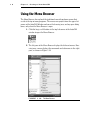
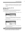
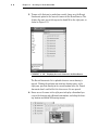
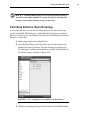
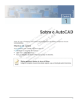
1
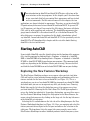
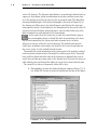
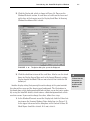
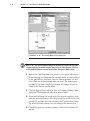
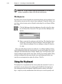
GH
TE
D
MA
TE
RI
AL
CHAPTER 1
CO
PY
RI
Getting to Know
AutoCAD
Opening a new drawing
Getting familiar with the AutoCAD and AutoCAD LT
graphics windows
Modifying the display
Displaying and arranging AutoCAD tools
2
Chapter 1 • Getting to Know AutoCAD
our introduction to AutoCAD and AutoCAD LT begins with a tour of the
user interfaces of the two programs. In this chapter, you’ll also learn how
to use some tools that help you control their appearance and how to find
and start commands. For the material covered in this chapter, the two
applications are almost identical in appearance. Therefore, as you tour AutoCAD,
I’ll point out any differences between AutoCAD and AutoCAD LT. In general, LT
is a 2D program, so it doesn’t have most of the 3D features that come with AutoCAD, such as solids modeling and rendering. The AutoLISP programming language found in AutoCAD is also absent from LT, as is the Action Recorder. The
other differences are minor. As mentioned in this book’s introduction, when I
say AutoCAD, I mean both AutoCAD and AutoCAD LT. I’ll also specifically refer to
AutoCAD LT as LT throughout this chapter and the rest of the book. Starting
AutoCAD is the first task at hand.
Y
Starting AutoCAD
If you installed AutoCAD using the default settings for the location of the program
files, start the program by choosing Start ➣ Programs ➣ Autodesk ➣ AutoCAD
2009 ➣ AutoCAD 2009 or by choosing Start ➣ Programs ➣ Autodesk ➣ AutoCAD
LT 2009 ➣ AutoCAD LT 2009, depending on your program. (This command path
might vary depending on the Windows scheme you are using.) You can also find
and click the AutoCAD 2009 icon or the AutoCAD LT 2009 icon on your desktop.
Exploring the New Features Workshop
The New Features Workshop welcome screen opens when you first start AutoCAD and leads to several animated demonstrations and explanations of the new
features included in the latest release of AutoCAD (see Figure 1.1). This is a
quick and easy way to see how AutoCAD 2009 has improved over AutoCAD 2008
and which tools you can use to augment any skills you already have. Choosing
Maybe Later on the left side of the dialog box causes it to reappear every time
you start AutoCAD. Choosing the No, Don’t Show This To Me Again option dismisses the dialog box indefinitely. If you chose that option, you must then access
the New Features Workshop through the Help option in the Menu Browser, the
menu system that you access by clicking on the large red A in the top-left corner
of the AutoCAD user interface.
Selecting the Yes radio button on the left side of the dialog box opens the New
Features Workshop dialog box (see Figure 1.2). Here, you navigate and select the
feature you want to investigate in the left pane and observe the selection in the
right pane. The drop-down list in the upper-left corner provides access to the
New Features Workshops for other Autodesk products installed on your system.
Starting AutoCAD
F I G U R E 1 . 1 : The AutoCAD welcome screen provides access to the New Features Workshop.
F I G U R E 1 . 2 : The New Features Workshop dialog box
The Customer Involvement Program
Nearly all the latest releases of Autodesk products include the opportunity to
participate in the customer involvement program (CIP). The CIP is designed to
collect nonpersonal information about your Autodesk products and computer
system to help the product programmers and developers design software that
3
4
Chapter 1 • Getting to Know AutoCAD
best meets their customers’ needs. If you haven’t yet agreed or declined to participate, when you first start AutoCAD, the Customer Involvement Program dialog box might prompt you to join.
Participation is strictly voluntary, and if you choose to participate, AutoCAD
will periodically send a small file to Autodesk containing information such as
your software name and version, the commands you use, and your system configuration information. An Internet connection is required, and you must ensure
that your firewall settings don’t prevent the information from being transmitted.
Exploring the AutoCAD User Interface
AutoCAD and LT
offer numerous dialog boxes with various combinations of
buttons and text
boxes. You’ll learn
many of their functions as you progress
through the book.
After bypassing the initial dialog boxes that AutoCAD provides, the program
opens to display the AutoCAD user interface, also called the graphics window.
AutoCAD provides many methods for creating and editing objects, changing the
view of a drawing, or executing AutoCAD file maintenance or other utilities. In
LT, your screen looks similar to Figure 1.3. For AutoCAD, your monitor displays
one of three workspaces:
The 2D Drafting & Annotation workspace (shown in Figure 1.3)
The AutoCAD Classic workspace
For AutoCAD users only, the 3D Modeling workspace (see Figure 1.4)
You’ll be using the 2D Drafting and Annotation workspace for the first 15
chapters in this book. In the final two chapters, you’ll switch to the 3D Modeling workspace, but for now, you need to get your AutoCAD user interface to
look like Figure 1.3.
The figures and graphics is this book show the drawing area of
the AutoCAD user interface with a white background, but the default, and preferred, method is to use a black background to reduce eyestrain. The color
choice in the book is simply for readability.
N O T E
Starting AutoCAD
F I G U R E 1 . 3 : The AutoCAD graphics window using the 2D Drafting & Annotation workspace
Tool Palettes
ViewCube
F I G U R E 1 . 4 : The AutoCAD graphics window using the 3D Modeling workspace
5
6
Chapter 1 • Getting to Know AutoCAD
If your screen looks like Figure 1.4 or isn’t at all like Figure 1.3, you need to
make a few changes:
1. Click the Workspace Switching button in the status bar and choose
2D Drafting & Annotation. Alternately, you can choose Tools ➣
Workspaces ➣ 2D Drafting & Annotation.
2. The 2D Drafting & Annotation workspace may display the tool palettes
on the screen. If the palettes are displayed, you need to turn them off
for now by clicking the X in the upper-right corner. Your workspace
might have different palettes displayed than those shown in Figure 1.5.
If other palettes are still visible, click the X in the upper-right or upperleft corner of each palette to close them.
LT users can skip
step 3 and move on
to step 4
F I G U R E 1 . 5 : The tool palettes
3. The large area in the middle of the screen is called the drawing area.
It might need adjusting. Enter visualstyles↵ to open the Visual Styles
Manager, and then click the 2D Wireframe option (see Figure 1.6).
Close the Visual Styles Manager.
Starting AutoCAD
F I G U R E 1 . 6 : Selecting the 2D Wireframe visual style
4. Enter plan↵ and then world↵ or click the World option in the pop-up
menu if it appears.
If dots appear in the drawing area, the grid is turned on.
5. Move the cursor to the left side of the status bar at the bottom of the
screen, and click the Grid Display button so it’s in the off (unpushed)
position and the dots disappear. Be sure all the other readout buttons
except Dynamic Input are in their off (unpushed) positions. You can
pause your cursor over each button to reveal its name in a tooltip.
Your screen should look similar enough to Figure 1.3 to continue.
7
8
Chapter 1 • Getting to Know AutoCAD
Introducing the AutoCAD
Graphics Window
The title bar and
menu bar at the top
of the LT screen are
identical to those in
AutoCAD except that
AutoCAD LT appears
in the title bar rather
than AutoCAD.
At the top of the graphics window sit the Ribbon, the Quick Access toolbar to the
left, and the InfoCenter and related tools on the right.
Quick Access
Toolbar
The title bar is analogous to the title bar in any Windows program. It contains
the program name (AutoCAD or AutoCAD LT) and the title of the current drawing with its path, as long as any drawing other than the default Drawingn.dwg is
open. Below the title bar is the Ribbon, where you’ll find most of the AutoCAD
commands and tools needed to complete any drawing task. Related tasks are
found under the different tabs, which are further segmented into panels containing similar tools.
To the far right of the title bar are the InfoCenter, Communications Center,
Favorites, and Help buttons. You can enter a question in the field to the left of the
InfoCenter button to quickly access information from the Help system through
the InfoCenter’s drop-down panel. With the Communications Center, you can
determine what type of information, such as software updates, product support,
or RSS feeds, Autodesk sends directly to your system. With the Favorites tool,
you can define a list of help or informational topics that can be quickly accessed
whenever you need them. The Help button is a direct link to the AutoCAD help
system.
The blank middle section of the screen is called the drawing area. Notice the
movable crosshair cursor. The crosshairs on your cursor might extend completely across the screen. Later in this chapter, I will show you how to modify the
length of the crosshairs as well as make a few other changes.
Notice the little box at the intersection of the two crosshair lines. This is one
of several forms of the AutoCAD cursor. When you move the cursor off the drawing area, it changes to the standard Windows pointing arrow. As you begin using
I n t ro d u c i n g t h e Au t o CA D G ra p h i c s Wi n d ow
commands, it will take on other forms, depending on which step of a command
you’re performing.
The icon with a double arrow in the lower-left corner of the drawing area is the
UCS icon (UCS stands for user coordinate system). It indicates the positive
direction for the x- and y-axes. You won’t need it for most of the chapters in this
book, so you’ll learn how to turn it off in Chapter 3.
Below the drawing area is the Command window.
When you enter commands in addition to using the Ribbon or pop-up menus,
the Command window is where you tell the program what to do and where the
program tells you what’s happening. It’s an important area, and you’ll need to
learn how it works in detail. Four lines of text should be visible. You’ll learn how
to increase the number of visible lines later in this chapter in the section “Working in the Command Window.” When the Dynamic Input feature is active, much
of the Command window information is displayed at the cursor as well.
Below the Command window is the status bar.
On the left end of the status bar, you’ll see a coordinate readout window. In the
middle are 10 buttons (LT has only 9) that activate various drawing modes. It’s
important to learn about the coordinate system and most of these drawing aids
(Snap Mode, Grid Display, Ortho Mode, Object Snap, etc) early on as you learn to
draw in AutoCAD. They will help you create neat and accurate drawings. Polar
Tracking and Object Snap Tracking are advanced drawing tools and will be introduced in Chapter 5. Dynamic UCS stands for Dynamic User Coordinate System; it’s
9
1 0
Chapter 1 • Getting to Know AutoCAD
used in 3D drawings. The Dynamic Input button is an on/off toggle that activates or
suppresses the dynamic display of information next to the crosshair cursor when
it’s in the drawing area. For now, keep it in the on (pushed) mode. The Show/Hide
Lineweight button toggles the display of lineweights (discussed in Chapter 14) in
the drawing area. When active, the Quick Properties tool displays the most common properties for the selected object(s) in a dialog box where they can be edited. If
you prefer text-based buttons rather than icons, you can right-click on any of the
tools mentioned here and uncheck the Use Icons option.
At the right side of the status bar are tools for controlling the appearance of annotation objects in AutoCAD, tools for navigating in the drawing area and controlling the display, and tools to control access to other
drawings or features within the current drawing. The padlock icon controls
which types of toolbars and windows are locked in their current positions on
the screen. Leave it in the unlocked mode for now.
To conclude this quick introduction to the various parts of the graphics window, I
need to mention a couple of items that might be visible on your screen. You might
have scroll bars below and to the right of the drawing area; although these can be
useful, they can take up precious space in the drawing area. They won’t be of any use
while working your way through this book, so I suggest you remove them for now.
To remove these features temporarily, follow these steps:
1. Enter options↵ to open the Options dialog box (shown in Figure 1.7). It
has 10 tabs (LT has only 8) across the top that act like tabs on file folders.
F I G U R E 1 . 7 : The Options dialog box
I n t ro d u c i n g t h e Au t o CA D G ra p h i c s Wi n d ow
1 1
2. Click the Display tab, which is shown in Figure 1.8. Focus on the
Window Elements section. If scroll bars are visible on the lower and
right edges of the drawing area, the Display Scroll Bars In Drawing
Window check box will be selected.
F I G U R E 1 . 8 : The Options dialog box open at the Display tab
3. Click the check box to turn off the scroll bars. Also be sure the check
boxes for Display Screen Menu and, in the Layout Elements section,
Display Layout And Model Tabs are not selected. Don’t click the OK
button yet.
Another display setting that you might want to change at this point controls
the color of the cursor and the drawing area background. The illustrations in
this book show a white background and black crosshair cursor, but you’re probably seeing the AutoCAD default, which features a black background and a white
crosshair cursor. If you want to change the colors, follow these steps:
1. In the Window Elements area of the Display tab, click the Colors button to open the Drawing Window Colors dialog box (see Figure 1.9).
In the upper-left corner of the dialog box, in the Context list box, 2D
Model Space should be selected. If it’s not, select it.
LT doesn’t have the
Screen menu, so
the option to turn
it off isn’t on LT’s
Display tab.
1 2
Chapter 1 • Getting to Know AutoCAD
F I G U R E 1 . 9 : The Drawing Window Colors dialog box
N O T E The screen-captured images in this book are taken from AutoCAD
sessions using the Dark Color Scheme. You can set the Color Scheme at the top
of the Window Elements area and choose either the Light or Dark scheme.
2. Move to the Color drop-down list, which is in the upper-right corner.
If your drawing area background is currently white, a square followed
by the word White is displayed. Open the Color drop-down list, and
select Black (or the background color you want). The drawing area
will now be that color, and the cursor color will change to white, as
shown in the Preview window below.
3. Click the Apply & Close button to close the Drawing Window Colors
dialog box. The background and cursor colors change.
4. If you want to change the length of the lines of your crosshair cursor,
go to the lower-right corner of the Display tab (the middle of the right
side for LT), and move the slider to change the Crosshair Size setting.
The crosshair length changes as a percentage of the drawing area.
5. Click OK to apply any remaining changes and close the Options dialog box.
Wo r k i n g i n t h e C o m m a n d Wi n d o w
T I P If you choose a color other than black as the drawing area background color, the color of the crosshair cursor remains the same as it was. To
change the crosshair color, in the Drawing Window Colors dialog box, go to
the Interface Element list box, and select Crosshairs. Then, select a color from
the Color drop-down list.
Working in the Command Window
Just below the drawing area is the Command window. This window is separate
from the drawing area and behaves like a Windows window—that is, you can drag
it to a different place on the screen and resize it, although I don’t recommend you
do this at first. If you currently have fewer than four lines of text in the window,
you should increase the window’s vertical size. To do so, move the cursor to the
horizontal boundary between the drawing area and the Command window until it
changes to an up-and-down arrow broken by two parallel horizontal lines.
Hold down the left mouse button, drag the cursor up by approximately the
amount that one or two lines of text would take up, and then release the mouse
button. You should see more lines of text, but you might have to try this a few
times to display exactly four lines. A horizontal line will separate the top two
lines of text from the bottom line of text. When you close the program, AutoCAD
will save the new settings. The next time you start AutoCAD, the Command window will display four lines of text.
The Command window is where you give information to AutoCAD and where
AutoCAD prompts you for the next step in executing a command. It’s good practice to keep an eye on the Command window as you work on your drawing. Many
errors can occur when you don’t check it frequently. If the Dynamic Input button on the status bar is in the on position, some of the information in the Command window will appear in the drawing area next to the cursor. I’ll cover this
feature when you start drawing.
Before you begin to draw in the next chapter, take a close look at the Ribbon,
Menu Browser, toolbars, and keyboard controls.
N O T E In many cases, you can start AutoCAD commands in a number of
ways: from the Ribbon, the Menu Browser, from the Command window, and
from menus that appear when you right-click. When you get used to drawing
with AutoCAD, you’ll learn some shortcuts that start commands quickly, and
you’ll find the way that is most comfortable for you.
1 3
1 4
Chapter 1 • Getting to Know AutoCAD
Using the Ribbon
New to AutoCAD 2009 is the Ribbon, a consolidated location for nearly all the AutoCAD tools in the form of easily recognizable buttons. A set of tabs delineates the different collections of tools by their purposes: creating and editing objects, adding
notes and dimensions, sending the drawing to a printer or plotter, and so on.
Displaying the Ribbon Tools
The Ribbon self-adjusts according to the width of the AutoCAD window. The panels have the most commonly used command as a button, larger than the others,
centered on the left side (see the top of Figure 1.10). When the width is too narrow to fully display each panel, the panels will begin to collapse first by replacing
the large buttons with smaller buttons and then by replacing the panels with a
single button bearing the name of the panel. The collapsed panel’s tools are displayed by clicking this single button, as shown at the bottom of Figure 1.10.
F I G U R E 1 . 1 0 : The Ribbon fully displaying all panels (top) and with partially and completely collapsed panels (bottom)
Collapsing, Moving, and Hiding the Ribbon
Available drawing area is always at a premium, and you can regain some
of it by collapsing the Ribbon. When you click the Minimize button to
the right of the Ribbon tabs once, the panels are collapsed vertically and only
show their titles. Clicking it a second time collapses the Ribbon further until
only the tabs show. When the Ribbon is in either of these states, you can expand
any panel or tab by clicking its visible panel or tab name. Clicking the Minimize
button a third time returns the Ribbon to its default state.
Using the Ribbon
The Ribbon’s default location is at the top of the screen, but it can be undocked,
or floating over the drawing area, or it can be moved to a second monitor or
docked on either side of the drawing area. To undock the Ribbon, right-click to
the right of the tab names and choose Undock from the pop-up menu.
The Ribbon detaches from the top of the drawing area and floats on the screen
as shown in Figure 1.11. To dock it, click the title bar on the side of the floating
Ribbon and drag it to the side or the top of the drawing area. Experiment with
detaching the Ribbon, but when you are finished, dock it back at the top so that
you can more easily follow the graphics in this book.
F I G U R E 1 . 1 1 : The Ribbon after undocking it from the top of the drawing area
If you don’t want the Ribbon at all, you can turn it off by right-clicking to the
right of the Ribbon tabs and choosing Close. To turn it on, enter ribbon↵. You’ll
use the Ribbon throughout this book.
Using the Ribbon Tools
Each panel contains tools from a related family of functions. For example, all the
common tools for editing objects in the drawing area are consolidated in the
Modify panel. When more tools are available than will fit on the panel, an arrow
is displayed on the panel’s title bar. Clicking the title bar expands the panel and
1 5
1 6
Chapter 1 • Getting to Know AutoCAD
exposes the additional tools. Follow these steps to learn how the Ribbon tools
work and how they display information.
1. Click the Home tab on the Ribbon to expose the Home tab’s panels.
2. Move the cursor over the Modify panel. The panel and panel title bar
change from light gray to white to indicate that that panel has the
program’s focus.
3. Pause the cursor over the Explode button to expose the button’s
tooltip as shown at the top of Figure 1.12. This tooltip displays the
name of the tool, a brief description of its function, the commandline equivalent of clicking the tool, and instructions to click the F1
key to open the AutoCAD Help file to the current tool’s Help page.
F I G U R E 1 . 1 2 : The tooltip for the Explode command (top) and the
extended tooltip (bottom)
4. After a few seconds of hovering over the Explode button, the tooltip
expands to display the extended tooltip (see the bottom of Figure 1.12)
with a more complete description.
5. Pause the cursor over the Copy button in the Modify panel. This time,
after a few seconds, the tooltip is replaced with a cue card, as shown
in Figure 1.13, instead of an extended tooltip. Cue cards show the
step-by-step implementation of the tool.
Using the Ribbon
F I G U R E 1 . 1 3 : The cue card for the Copy tool
6. Click the Modify panel’s title bar to expand the panels and expose all
of the Modify tools.
7. Often, you may find yourself returning to the same tool on an expanded
Ribbon panel. When that happens, you can pin the panel open by clicking the pushpin-shaped button in the bottom-right corner. When the
panel is pinned open, it remains open even when the cursor is not hovering over it.
8. Click the button again to unpin the panel and then move the cursor
off the panel to collapse it.
Customizing the Ribbon
You can customize each panel of the Ribbon, and you can build your own custom
tabs and panels to display only the buttons you use frequently. You can even design
your own buttons for commands that aren’t already represented by buttons on the
toolbars. These activities are for more advanced users, however, and aren’t covered
in this book. To find out more about how to customize toolbars, see Mastering
AutoCAD 2009 and AutoCAD LT 2009 by George Omura (Wiley, 2008).
1 7
1 8
Chapter 1 • Getting to Know AutoCAD
Using the Menu Browser
The Menu Browser has replaced the traditional row of drop-down menus that
reside at the top of many programs. The menus now project from the upper-left
corner of the AutoCAD Window and cover the drawing area, and any open dialog
boxes, only when the Menu Browser is open.
1. Click the large, red A button in the top-left corner of the AutoCAD
window to open the Menu Browser.
2. The left pane of the Menu Browser displays the different menus. Hovering over a menu displays the commands and submenus in the right
pane, as shown in Figure 1.14.
F I G U R E 1 . 1 4 : The Menu Browser
Using the Menu Browser
3. Submenus are identified by the pale, right-facing arrows to the left of
their names. Click this arrow, or the name of a submenu, to expand it
and display the tools. Click in the same location again to collapse the
submenu.
Opening a Drawing with the
Menu Browser
The Menu Browser offers a quick method for opening drawings. You can even
see a thumbnail preview of the drawings and arrange drawings that you frequently edit so that they are easily accessible. Here’s how:
1. To open a new AutoCAD file from the Menu Browser, click File ➣ New.
This opens the Select Template dialog box, where you select a template to base the new drawing on. Opening a file with a template is
covered in Chapter 2.
2. To open an existing file from the Menu Browser, click File ➣ Open.
This opens the Select File dialog box where you can navigate to and
select the desired drawing file.
You can open new or existing files using the QNew or Open buttons
in the Quick Access toolbar. Existing drawings can also be opened by dragging them from a Windows Explorer window to the AutoCAD title bar.
T I P
1 9
2 0
Chapter 1 • Getting to Know AutoCAD
3. To open a file that you’ve worked on recently, hover over the Recent
Documents option in the lower-left corner of the Menu Browser. This
displays the most recent files opened in AutoCAD in the right pane, as
shown in Figure 1.15.
F I G U R E 1 . 1 5 : Displaying the recent documents in the Menu Browser
The Recent Documents list is updated whenever a new drawing is
opened. Clicking the pushpin icon next to a drawing name, in the
right pane, pins that drawing to its current location in the list. Pinned
documents don’t scroll off the list when newer files are opened.
4. Hover over a file name in the right pane to display a thumbnail preview of the drawing and additional information, including the drawing location and AutoCAD drawing format.
Using the Menu Browser
N O T E AutoCAD 2009 drawing files use the same drawing format as
AutoCAD versions 2008 and 2007. This means that the files are compatible
between versions without requiring any type of conversion.
Switching Between Open Drawings
As in many programs, you can have multiple drawing files open in the same
session of AutoCAD. Each drawing is stacked behind the drawings in front of it.
There are several ways to switch between the open file including using the Menu
Browser, as shown here.
1. Start or open two or more AutoCAD files.
2. Open the Menu Browser and then hover over the Open Documents
option in the lower-left corner. The open drawings are displayed in
the right panel, and the current drawing is marked with a blue dot to
the left of its name, as shown in Figure 1.16.
F I G U R E 1 . 1 6 : Displaying the open drawings in the Menu Browser
3. Click on any drawing to bring it to the front of the AutoCAD window.
2 1
2 2
Chapter 1 • Getting to Know AutoCAD
Another option for switching between open drawings is to click the
Quick View Drawings button in the status bar. This displays thumbnails for the open drawings, and you can click any thumbnail to make
that drawing active.
Using the Drop-Down Menus
If you prefer to use drop-down menus, they’re still available in AutoCAD 2009,
although they are turned off by default in the 2D Drafting & Annotation and 3D
Modeling workspaces. You can display them by switching to the AutoCAD Classic
workspace, by right-clicking on the Quick Access toolbar and choosing Show
Menu Bar, or by entering menubar↵ 1↵. The menu bar isn’t used in the exercises in this book, but I’ll cover the menus here in case you want to use them in
the future.
The left end of the menu bar, just below the title bar (see Figure 1.17), consists
of an icon and 12 (11 if you don’t have the Express Tools installed or are using LT)
menus. Click any of these to display a drop-down menu. The icon and the File and
Edit menus are included with all Windows-compliant applications, although they
are somewhat customized to work with AutoCAD. The drop-down menu associated with the icon contains commands to control the appearance and position of
the drawing area.
F I G U R E 1 . 1 7 : The AutoCAD user interface showing the menu bar
Commands in the File menu are for opening and saving new and existing drawing files, printing, exporting files to another application, choosing basic utility
options, and exiting the application. The Edit menu contains the Undo and Redo
commands, the Cut and Paste tools, and options for creating links between AutoCAD files and other files. The Help menu works like most Windows Help menus
and contains a couple of AutoCAD-specific entries as well, including some online
resources and a link to the New Features Workshop.
U s i n g t h e To o l b a r s
The other eight (or nine) menus contain the most frequently used AutoCAD
commands. You’ll find that if you master the logic of how the commands are
organized by menu, you can quickly find the command you want. Here is a short
description of each of the other AutoCAD drop-down menus:
View
Contains tools for controlling the display of your drawing file.
Insert Contains commands for placing drawings and images or parts of them
inside other drawings.
Format Contains commands for setting up the general parameters for a new
drawing or changing the entities in a current drawing.
Tools Contains special tools for use while you’re working on the current drawing, such as those for finding the length of a line or for running a special macro.
Draw Contains commands for creating new objects (such as lines or circles) on
the screen.
Dimension
Modify
Contains commands for dimensioning and annotating a drawing.
Contains commands for changing existing objects in the drawing.
Window Contains commands for displaying currently open drawing windows
and lists currently open drawing files.
Express Contains a library of productivity tools that cover a wide range of
AutoCAD functions. Express Tools are widely used but unsupported directly by
Autodesk. They might or might not be installed on your computer.
You can turn off the menu bar by right-clicking on the Quick Access toolbar
and choosing Show Menu Bar or by entering menubar↵ 0↵.
Using the Toolbars
The AutoCAD toolbars have essentially been replaced by the Ribbon, so I’ll only
touch on them briefly here. Toolbars, like the Ribbon panels, are collections of
tools grouped by similar tasks. Like the Ribbon itself, any toolbar can be displayed or hidden without affecting the others, and they can all be docked to a
side or the top of the drawing area or float freely. To display a toolbar, right-
2 3
2 4
Chapter 1 • Getting to Know AutoCAD
click on the Quick Access toolbar, click Toolbars, click a toolbar category, and
then click the toolbar that you want to open.
LT has only 23
Standard toolbar
buttons. It doesn’t
have the Sheet Set
Manager and Block
Editor buttons
because LT doesn’t
offer these features.
Take a few minutes to explore the available toolbars, and then open the Standard toolbar from the AutoCAD or AutoCAD LT category.
The icons on the AutoCAD toolbars look like flat images and don’t appear as
raised buttons until you point to them. The Standard toolbar has 25 icons, and
they are arranged into seven logical groups. The icons on the left half of the
Standard toolbar are mostly for commands used in all Windows-compatible
applications, so you might be familiar with them. The icons on the right half of
the Standard toolbar are AutoCAD commands that you use during your regular
drawing activities. You can use these commands to take care of a number of
tasks, including the following:
Changing the view of the drawing on the screen
Changing the properties of an object, such as color or linetype
Borrowing parts of an unopened drawing to use in your current
drawing
Displaying a set of palettes that contain objects you can use in your
drawing
Accessing the Toolbar Fly-Out Menus
Notice that one icon on the Standard toolbar has a little triangular arrow in the
lower-right corner. This arrow indicates that clicking this icon displays more than
one command. Follow these steps to see how this special icon works:
1. Move the cursor to the Standard toolbar, and point to the icon that
has a magnifying glass with a rectangle in it.
2. Rest the arrow on the button for a moment without clicking to display the tooltip. Notice the small arrow in the lower-right corner of
the icon. This is the multiple-command arrow mentioned earlier.
U s i n g t h e To o l b a r s
2 5
3. Place the arrow cursor on the button, and hold down the left mouse
button. A column of nine buttons opens vertically below the original
button (see Figure 1.18). The top button in the column is a duplicate
of the button you clicked. This column of buttons is called a toolbar
fly-out menu. In this example, you’re working with the Zoom toolbar
fly-out menu.
F I G U R E 1 . 1 8 : A toolbar fly-out menu
4. To dock a floating toolbar, click the grab bar and drag the toolbar to
either side of the drawing area or to just below the AutoCAD title bar
and release.
5. To detach a docked toolbar, click the grab bar and drag the toolbar
into the drawing area.
6. Close any open toolbars by undocking them then clicking the X in
the upper-right corner of each.
The toolbar fly-out menus are regular toolbars that have been attached to
another toolbar. AutoCAD has 38 toolbars in all, but only a few have fly-out
menus—the Zoom fly-out menu I just discussed and the Insert fly-out menu on
the Draw toolbar, for example.
Grab bars are the two
lines at the left end of
a horizontal toolbar
or at the top of a vertical one. They represent the one place to
grab a docked toolbar
to move it.You can
also change a docked
toolbar into a floating
toolbar by doubleclicking its grab bars.
2 6
Chapter 1 • Getting to Know AutoCAD
N O T E LT has 27 toolbars compared with AutoCAD’s 38. The additional
toolbars in AutoCAD are almost all for 3D and rendering tools.
Workspaces
You haven’t been directed to make any significant changes to the workspace, but
when you do, you can save this setup as a new workspace. Using this feature, you
can always return to your preferred layout by activating the saved layout. Follow
these steps:
1. Click the Workspace Switching button on the right side of the status
bar and choose Save Current As. This opens the Save Workspace dialog box.
2. Enter a name for the workspace and click Save. The dialog box closes,
and you are returned you to your workspace. Until you change it or
select a different workspace, the new workspace setup will remain as
it is now.
When you make changes to the new workspace—by adding a toolbar or changing the background color of the drawing area—you can easily update the current
workspace to accommodate those changes. Follow steps 1 and 2 previously, naming the workspace again with the same name. You’ll get a warning window telling
you that a workspace by that name already exists and asking you whether you
want the new arrangement to replace the old one. Click Yes.
Using the Keyboard
The keyboard is an important tool for entering data and commands. If you’re a
good typist, you can gain speed in working with AutoCAD by learning how to
enter commands from the keyboard. AutoCAD provides what are called alias
keys—single keys or key combinations that start any of several frequently used
Using the Mouse
commands. You can add more or change the existing aliases as you get more
familiar with the program.
In addition to the alias keys, you can use several of the F keys (function keys)
on the top row of the keyboard as two-way or three-way toggles to turn AutoCAD
functions on and off. Although buttons on the screen duplicate these functions
(Snap, Grid, and so on), it’s sometimes faster to use the F keys.
While working in AutoCAD, you’ll need to enter a lot of data, such as dimensions and construction notes; answer questions with “yes” or “no,” and use the
arrow keys. You’ll use the keyboard constantly. It might help to get into the
habit of keeping your left hand on the keyboard and your right hand on the
mouse if you’re right-handed, or the other way around if you’re left-handed.
Using the Mouse
Your mouse most likely has two buttons and a scroll wheel. So far in this chapter, you have used the left mouse button to choose menus, commands, and
options, and you’ve held it down to drag menus, toolbars, and windows. The left
mouse button is the one you’ll be using most often, but you’ll also use the right
mouse button.
While drawing, you’ll use the right mouse button for the following three
operations:
To display a menu containing options relevant to the particular step
you’re in at the moment
To use in combination with the Shift or Ctrl key to display a menu
containing special drawing aids called object snaps
To display a menu of toolbars when the pointer is on any icon of a
toolbar that is currently open
If you have a three-button mouse, the middle button is usually programmed
to display the Object Snap menu, instead of using the right button with the
Shift key. If you have a mouse with a scroll wheel, you can use the wheel in several ways to control the view of your drawing. I’ll cover those methods in subsequent chapters.
AutoCAD makes extensive use of toolbars and the right-click menu feature.
This makes your mouse an important input tool. The keyboard is necessary for
inputting numeric data and text, and it has hot keys and aliases that can speed
up your work; however, the mouse is the primary tool for selecting options and
controlling toolbars.
2 7
2 8
Chapter 1 • Getting to Know AutoCAD
The next chapter will familiarize you with a few basic commands that will
enable you to draw a small diagram. If want to take a break and close AutoCAD,
choose File ➣ Exit, and choose not to save the drawing.
Are You Experienced?
Now you can…
0 recognize the elements of the AutoCAD graphics window
0 understand how the Command window works and why it’s
important
0 start commands from the Ribbon
0 start commands from the command line
0 use the Menu Browser
0 display the drop-down menus
0 open and control the positioning of toolbars
0 save a workspace of your screen setup in AutoCAD