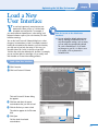
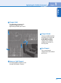
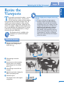
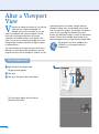
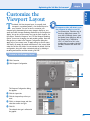
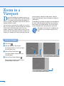
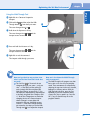
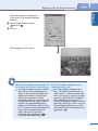
1
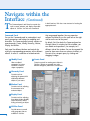
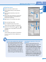
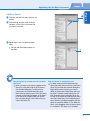
Understanding the
3ds Max Interface
reactor toolbars — are visible within the 3ds Max window.
The Main toolbar docks at the top of the window, and the
reactor toolbar docks on the left side of the window.
However, you can dock or move any toolbar to any location
within the window. If you prefer, you can also allow the
toolbars to float within the window.
Y
TE
RI
A
L
ou can use the 3ds Max interface to access all of
the features that create and modify objects and
animations. 3ds Max provides a feature-rich,
customizable user interface with a Menu bar, toolbars,
Timeline, Track bar, Command panels, and one or more
viewports. Although 3ds Max comes with seven different
toolbars, by default, only two toolbars — the Main and
A Menu Bar
B Main Toolbar
MA
Allows you to perform
commonly used commands
within 3ds Max.
D Viewports
D
E
TE
GH
RI
C
D
D
Show different views of
your objects. You can
display up to four
viewports in the center of
your 3ds Max window.
D
F
E Command Panels
Contain six different panels
with commands that allow
you to model, modify,
animate, and display objects.
4
A
D
PY
Contains buttons that
perform common
reactor functions,
such as creating rigid
and soft body
collections, displaying
physical properties of
objects, generating
simulations, and
running the real-time
preview utility.
B
CO
C Reactor Toolbar
Has commands for creating
and modifying objects and
animations.
F Viewport Navigation Controls
Allow you to zoom, pan, and navigate
within the viewports. These controls
change, depending on the type of
viewport selected.
Optimizing the 3ds Max Environment
chapter
1
PART I
A Animation Playback Controls
Allow you to review an animation in
the viewports. You can play the entire
animation, view individual frames, or
jump to a specific frame.
B Track Bar
Displays keyframes
for the selected
object or objects.
C Time Slider
Indicates the current
frame displayed in the
viewports. You can move
the Time Slider to change
the current frame.
D Coordinate Display
Indicates the position of
the cursor using absolute
world coordinates (X, Y,
Z). When you transform
an object, the display
shows the object
coordinates relative to its
coordinates before
transformation.
C
F
B
D
F MAXScript Mini-Listener
Allows you to write scripts using the
MAXScript language to control 3D
objects and animations.
E
A
E Animation Keying
Controls
Display options that allow
you to create keys for
animating your objects.
5
Navigate within the Interface
Y
needs. For example, you can create a custom toolbar with
the commands and tools that you use most frequently and
dock it where it is most convenient for your workflow.
ou can customize the four different 3ds Max
interface elements — toolbars, menus, panels, and
viewports — to create a layout that matches your
Viewports
Viewports, located in the center of the 3ds Max
window, help you construct your scenes by creating
and animating objects. Each viewport shows the scene
from a different viewpoint, such as the top, left, or front,
or through a camera or light. Viewports can also show
a scene in perspective — with points of convergence —
or axonometric — without points of convergence. You
can specify the number of viewports display, and then
assign a specific type of view to each viewport.
You can customize the appearance of the scene
within each viewport independently of the other
viewports. For more information, see the section
“Customize the Viewport Layout.”
A Docked Toolbar
A toolbar attached to the
top, bottom, or one of the
sides of the 3ds Max window.
Toolbars
Toolbars contain buttons that allow quick access to
3ds Max’s commands and tools. You can create
custom toolbars to fit your particular workflow or use
3ds Max’s default toolbars. Although, by default, the
Main toolbar is docked at the top of the window and
the reactor toolbar is docked on the left side of the
window, you can position toolbars wherever you want.
By default, 3ds Max hides floating toolbars, but you
can view them per the instructions in the section
“Create a Custom Toolbar.” If you prefer, you can
display only specific floating toolbars by right-clicking
an empty spot on any toolbar and selecting the
toolbar you want from the menu.
B Docking Toolbar in Progress
When the cursor changes from
to
, you can
release the mouse to dock a toolbar. When you
undock a toolbar,
changes to
indicating that
the toolbar will float.
A
B
A
C
C
C Floating Toolbar
Any toolbar that floats on your main screen or a second monitor. You can move, resize,
or close a floating toolbar. You can reposition any floating toolbar to the edge of a
viewport by dragging its edge to where you want to dock it. Likewise, you can reverse
the process to undock the toolbar.
6
Optimizing the 3ds Max Environment
chapter
1
PART I
3ds Max Button Types
3ds Max has five basic button types: standard
buttons, modal buttons, toggle buttons, flyout
buttons, and drop-down lists that display on
toolbars. You can create new toolbars and customize
A Standard Button
existing toolbars by adding and removing buttons
through the Customize User Interface dialog box.
See the section “Create a Custom Toolbar” for more
information on working with toolbars.
B Toggle Button
When you click a
standard button, it
immediately performs
the corresponding
command.
C Modal Button
These buttons switch specific
settings on or off. These settings
apply to the next action, such as
the next mouse-click. When you
depress a toggle button, the
corresponding settings are on.
These buttons specify an exclusive
setting for subsequent mouse
actions. For example, the Select
Object button selects the next
object that you click. The button
remains selected until you click
another button.
View
D
A
A
C
B
E
D Flyout Buttons
Conceals related buttons. A small arrow ( ) in the
lower-right corner of the button indicates a flyout.
You can click and hold
to display the flyout
buttons, and click the button that you want.
E Drop-down List
You can click the down arrow ( ) beside a list
to select from the available options. For
example, the Selection Filter drop-down list
contains a list of object types that can be
selected.
7
Navigate within the
Interface (Continued)
T
in both locations. Each has a tree structure for locating the
appropriate tools.
he Command panels and Menu bar contain the
tools to create, animate, and display all possible
objects in 3ds Max. You find most commands
Command Panel
You use the Command panel to create objects and
specify parameters and settings for modeling and
animation. The Command panel actually contains six
separate panels: Create, Modify, Hierarchy, Motion,
Display, and Utilities.
Each panel has different buttons and controls for
setting the corresponding parameters within different
rollouts. A rollout is a collection of related controls
B Modify Panel
Alters an object’s
parameters or assigns
modifiers to alter its
shape or properties.
Contains controls for creating most objects in
3ds Max. Objects are grouped into seven
different categories, each with its own button.
E
B
A
D Motion Panel
Contains tools for adjusting
the movement of an
animated object.
E Display Panel
Contains tools for adjusting
how objects display globally
within the scene, such as
hiding or freezing an object.
F Utilities Panel
Provides access to several
utility programs that are
available in 3ds Max.
8
By default, 3ds Max docks the Command panel on
the right side of its window, but like a toolbar, you
can undock and reposition it, for example, to a
different side of the window. You can also expand the
panel to show more than one column of rollouts, at
the cost of less viewport space, by clicking and
dragging its edges.
A Create Panel
C Hierarchy Panel
Contains tools for
adjusting the parent/child
relationship between
objects in your scene.
that are grouped together. You can expand or
collapse the rollout or use the scroll bar on the right
side to see the rest of the panel.
F
C
D
Optimizing the 3ds Max Environment
A Pop-up Menu
Contains options
for customizing a
feature’s
appearance. For
example, when
you right-click a
toolbar, a menu
appears,
displaying
information such
as a list of all
visible toolbars,
as well as
whether the
toolbar is docked
or floating.
A
1
3ds Max has two other types of menus: the pop-up
menu and the quad menu. Pop-up menus appear
when you right-click the toolbars, rollouts, and
viewport titles. Quad menus appear when you
right-click objects, or in viewports. Although both
types of menus display when you right-click them,
you can only customize the quad menus. See the
section “Create a Custom Quad Menu” for more
information.
B
PART I
Menus
As with any Microsoft Windows–compliant program,
3ds Max provides drop-down menus on the Menu
bar that access most of the program’s features. You
can view the menu options by clicking the
corresponding menu on the Menu bar. You can
customize each menu by adding and removing
menu options. You can also create new custom
menus that you can add to the Menu bar. See the
section “Create a Custom Menu” for more
information on customizing menus.
chapter
B Quad Menu
Contains between
one and four smaller
menus arranged in
quadrants. Each
smaller menu has its
own Title bar. The
most commonly
used quad menus
display when you
right-click an object
in a viewport. You
can also access quad
menus that display
when you press a
specific key
sequence.
9
Create a New
Keyboard Shortcut
want to perform and then specify the keyboard shortcut
sequence.
Y
ou can create new keyboard shortcuts for
commands and tools that you use often within
3ds Max. Keyboard shortcuts help you to save
time when your projects require a lot of repetitive
command combinations.
You can make a keyboard shortcut active for the Main user
interface (UI), or for a specific program context, such as
the Material Editor. If you select the Main UI, the keyboard
context is available anywhere in 3ds Max. If you specify
another context, then any shortcuts that you create are
only available when you work with that feature. After you
specify the context area, you can select the action that you
If the keyboard sequence that you specify is already
assigned to a command in the selected context, the
command appears in the Assigned To field. To keep
the current keyboard shortcut, you must specify a
different one.
3ds Max allows you to create the same keyboard shortcut
for multiple contexts. When you press a keyboard shortcut,
3ds Max checks for a context-specific shortcut first. If one
does not exist, then it looks for a keyboard shortcut in the
Main UI shortcuts.
Create a New Keyboard Shortcut
1
2
Click Customize.
Customize
Customize User Interface...
Click Customize User Interface.
4
The Customize User Interface dialog box
appears.
3
4
Click the Keyboard tab.
Click here and select the context for which
you want your keyboard shortcut to be active.
10
3
Main UI
1
2
chapter
Optimizing the 3ds Max Environment
In the Action list, click the command or tool
for which you want to assign a keyboard
shortcut.
•
6
7
Press the keyboard sequence that you want.
•
6
Click in the Hotkey field.
•
8
•
You can select a specific category in the
Category field to display only a specific
group of actions.
5
Extrude [Poly]
The keys that you press appear in the
Hotkey field.
Click Assign.
•
The assigned key sequence appears in the
Shortcut column next to the corresponding
command.
8
•
My keyboard shortcut does not work. What
are some possible reasons for this?
3ds Max allows you to select whether the
context-specific keyboard shortcuts are active.
If you do not activate context-sensitive
keyboard shortcuts, you can only use the
keyboard shortcuts for the Main UI. To activate
the context-specific keyboard shortcuts,
click the Active option ( changes to ) in
the Keyboard panel of the Customize User
Interface dialog box. You must also turn on the
Keyboard Shortcut Override Toggle button,
which is in the Extras toolbar. To display the
Extras toolbar, right-click in a blank area of a
toolbar and select Extras.
How do I know which keyboard shortcuts are
assigned?
You can create a list of current keyboard
shortcuts to either view or print. To do this,
click Write Keyboard Chart in the Keyboard
panel of the Customize User Interface dialog
box. In the Save File As dialog box that
appears, give the file a name and destination,
and then open it in any application that can
read TXT files. You can also click Help and then
click HotKey Map to display a flash-based list of
common keyboard shortcuts. When you place
the cursor over keys in the keyboard graphic in
the lower-right corner, 3ds Max displays the
associated shortcuts.
11
PART I
5
1
Create a Custom
Toolbar
Y
ou can create a new toolbar that contains a custom
set of buttons for specific commands and tools that
you often use in 3ds Max. This can streamline your
work flow by reducing the time it takes to access tools that
you may have buried in a flyout menu. You can also add
any of the 3ds Max tools and commands to your toolbars
and create buttons for custom MAXScript scripts.
You create new toolbars and add buttons to toolbars using
the New button on the Toolbars panel in the Customize
User Interface dialog box. 3ds Max displays a blank toolbar
to which you can add buttons, either from the Action list in
the Toolbars panel or from another open toolbar.
By default, the Action list contains all of the available
commands and tools in 3ds Max. You can reduce the list
by selecting a specific group in the Group field or a specific
category in the Category field. For example, if you select
the Main UI in the Group field, you can select Edit in the
Category field to view only the available editing commands.
Create a Custom Toolbar
Create a New Toolbar
Customize
1
2
Click Customize.
Click Customize User Interface.
•
•
To view all hidden toolbars, you can click
Show UI, and then click Show Floating
Toolbars in the dialog box that appears.
The Customize User Interface dialog box
appears.
3
4
1
Customize User Interface...
Click the Toolbars tab.
Click New.
3
4
12
2
Optimizing the 3ds Max Environment
chapter
1
PART I
The New Toolbar dialog box appears.
5
6
5
Type a name for your new toolbar.
Click OK.
6
Add Buttons to a Toolbar
•
7
In the Action list, click the tool or command
that you want to add to your toolbar.
•
8
9
3ds Max creates a toolbar with the name
you specified.
Drag the selection to the toolbar.
Repeat steps 7 and 8 to add more buttons
to the toolbar.
3ds Max adds the selected buttons to the
toolbar.
Add Hair Modifier
7
8
How can I copy buttons from
one toolbar to another?
You must have both toolbars
open, although you do not
need to open the Customize
User Interface dialog box.
Press and hold the Control
key, and then drag a button
from the source to the
destination toolbar. Release
the mouse when you see a
small rectangle cursor.
The button now resides in
both toolbars. Pressing
and holding the Alt key while
dragging a button moves it
from one toolbar to the other.
Can I dock my custom toolbar
in the 3ds Max window?
Yes. Your custom toolbar can
either float in the 3ds Max
window or dock along the top
or side of the window. To
dock your toolbar, click and
drag it to the location that
you want, as described in the
section “Navigate within the
Interface.” For example, to
dock the toolbar at the top of
the window, simply click and
drag it there. Short toolbars
can dock side by side or one
above the other.
How do I remove unwanted
buttons?
You can remove buttons from
any toolbar, whether it is
custom or default. Right-click
the button that you want to
remove and then select Delete
Button from the menu. A
dialog box appears to confirm
your selection. Click Yes to
remove the button. For
buttons that have a right-click
function assigned to them,
such as the Undo button,
press and hold the Alt key
and drag the button into a
viewport to delete it.
13
Create a Custom
Quad Menu
Y
ou can create custom quad menus that contain
specific commands, tools, and menus that you
frequently use in 3ds Max. Quad menus display
when you right-click in a viewport or on an object, or when
you press a specific keyboard shortcut. Quad menus are so
named because they are menus that can contain up to four
smaller menus, or quadrants. Each quadrant menu can have
a separate label to identify the options in that menu.
You can create quad menus in the Quads panel of the
Customize User Interface dialog box. You can also assign a
keyboard shortcut for displaying the quad menu. After
creating the quad menu set, you can place options to it
from either the Action list or the Menus list. You can use the
Separator object to create visual separations between
related menu options.
You can specify that the quad menu display all quad menus
in all quadrants at one time, or only one quadrant at a
time. If you do not select the Show All Quads option, then
only one quad menu displays at a time, along with the
corner of each additional quad menu.
Create a Custom Quad Menu
Create a new Quad Menu
1
2
1
Customize
Customize User Interface...
Click Customize.
2
Click Customize User Interface.
The Customize User Interface dialog box
appears.
3
4
Click the Quads tab.
Click New.
The New Quad Set dialog box appears.
5
6
3
4
Type a name for your new quad set.
Click OK.
5
3ds Max creates a quad menu set with the
name that you specified.
6
14
chapter
Optimizing the 3ds Max Environment
1
7
8
9
0
!
@
#
7
Click here and select the quad set menu.
Click the quadrant where you want to place the
command.
8
Type the quadrant name that you want in the
Label field.
Click an option from the Action list or a menu from
the Menus list and drag it to the Quad Menu list
above the End of Menu entry.
0
#
Click in the Quad Shortcut field.
Press the keyboard sequence that you want.
@
Click the Show All Quads option (
changes to
).
This displays menus in all quadrants for your custom
quad menu.
%
Bind Space Warp Mode
Repeat steps 8 to 10 to add more menu options.
The keys that you press appear in the Hotkey field.
$
9
$
%
Click Assign.
3ds Max adds the menu options to the quad menu.
You can now type the shortcut to display the new
quad menu.
How do I remove options from a quad menu?
You can remove menu items from any quad
menu through the Quads tab of the Customize
User Interface dialog box. To remove a menu
option, first select the quad set menu in the
Quad Set List list box in the top-right corner of
the Quads tab. Click to select the quadrant
containing the menu that you want to modify.
A list of the menu options for that quadrant
appear in the Quad Menu window. Right-click
the menu item in the Quad Menu window. In
the menu that appears, click Delete Menu Item.
Can I change the appearance of my custom
quad menu?
Yes, you can make several changes to the
appearance of the quad menus. However, your
changes affect all quad menus. To make
changes, click Advanced Options in the Quads
tab of the Customize User Interface dialog box.
In the Advanced Quad Menu Options dialog
box that appears, you can change the colors
of different elements of the quad menu. For
example, you can change the color of the title
background, select different font types and sizes,
and specify the type of animation used to display
the quad menus. You can add transparency to
the quad menus by using the Opacity Amount
field in the Advanced Options dialog box.
15
PART I
Add Quad Menu Options
Create a
Custom Menu
Y
ou can create new custom menus that contain your
preferred tools and commands. After creating a
custom menu, you can add the menu to any of the
system Menu bars, or to a specific quad menu. For
example, you can create a custom menu that appears in
the Main Menu bar.
You can create new menus through the Menus panel of the
Customize User Interface dialog box. In addition to creating
new menus in this panel, you can also customize the
appearance of any menu by adding, moving, or removing
menu items.
You can add items to a menu by dragging them from one
of the lists on the left side of the panel into the Menu
window. The Action list window contains all of the
commands and tools that are available in 3ds Max. You
can drag the Separator onto the Menus list to create a
visual separation line between menu items. The Menus list
contains all of the available menus. When you add a
submenu to your menu, it becomes a separate submenu.
Create a Custom Menu
1
Create a New Menu
Customize
1
2
Customize User Interface...
Click Customize.
Click Customize User Interface.
The Customize User Interface dialog box
appears.
3
4
Click the Menus tab.
3
4
Click New.
The New Menu dialog box appears.
5
6
5
Type a name for your new menu.
Click OK.
3ds Max creates a menu with the name that
you specified.
16
6
2
Optimizing the 3ds Max Environment
chapter
1
7
8
9
Click here and select the menu that you just
created.
7
-- End of Menu --
8
Click and drag an option from the Action,
Separator, or Menus list to the menu that
you want to customize.
Repeat steps 7 and 8 to add more menu
items.
•
3ds Max adds the selected options to
the menu.
How do I place my custom menu on the Main
Menu bar?
When you create a new menu, it appears in the
Menus list in the Menus tab of the Customize
User Interface dialog box. To add your new
custom menu to the Main Menu bar, select
Main Menu Bar from the menu. All of the menus
currently on the Menu bar appear. In the Menus
list on the left of the panel, click your custom
menu and then drag it to the location that you
want in the Menus list.
Line Shape
•
How do I delete an unwanted menu?
To delete a menu from the Main Menu bar,
select Main Menu Bar from the list in the Menus
tab of the Customize User Interface dialog box.
Right-click the menu item that you want to
delete, and then select Delete Menu Item from
the menu. To delete a menu entirely from 3ds
Max, locate the menu in the Menus list on the
left side of the Menus tab. Right-click the menu
and select Delete Menu. If the selected menu is
also a submenu, a dialog box appears with the
option to cancel the deletion. If you delete the
menu, it also disappears from any menus where
it is a submenu. This action is not undoable.
17
PART I
Add Menu Options
Customize the
Interface Colors
Y
ou can customize the appearance of your 3ds Max
interface by customizing the colors of the different
elements through the Colors panel of the
Customize User Interface dialog box. This panel has two
different lists: the Elements list and the Scheme list. The
Elements list contains all of the elements within a specified
user category, such as Viewports. You can select the user
interface category in the Elements list. The Scheme list
contains the custom colors that affect the entire user
interface. For example, when you change the text color, it
changes the background color of all non-menu text in all
rollouts, buttons, dialog boxes, and message boxes. You
must select Custom Colors in the Scheme list to customize
these features.
There are two Color fields on the right side of the Colors
panel. The top field displays the color of the selected
element, and the bottom field displays the color of the
selected scheme option. You can change the color for a
selection in the Color Selector dialog box using one of the
three color modes: the color spectrum on the left, which
specifies the Hue, Blackness, and Whiteness; the Red, Green,
and Blue fields; or the Hue, Saturation, and Value fields.
Customize the Interface Colors
1
2
Click Customize.
Customize User Interface...
Click Customize User Interface.
3
The Customize User Interface dialog box
appears.
3
4
Click the Colors tab.
6
5
6
Camera Object
Click here and select the element category
that you want.
The Elements list changes to display only the
elements in that category.
5
1
Customize
In the Elements list, click the element that you
want to change.
Click the Color field.
18
4
Dark Shadow
2
chapter
Optimizing the 3ds Max Environment
1
7
8
Click a new color in the Color Spectrum field.
Click and drag the slider ( ) in the Whiteness
field to adjust the amount of white in the color
selection.
•
8
Click Close.
•
0
9
•
9
You can also click the spinners ( ) for the
Red, Green, Blue, Hue, Sat, and Value fields
to specify the color that you want.
•
7
The new color for the selection displays in
the corresponding Color field.
Camera Object
Click Apply Colors Now.
3ds Max applies all color changes that you have
made to the user interface.
3D Dark Shadow
0
How do I get rid of color changes that I have
made?
When you click Apply Colors Now, 3ds Max
applies your color changes to the user interface.
The only way to undo the color changes is to
reset the interface back to the last saved version
of the color settings. To do this, click Reset at
the bottom of the Colors panel. See the
section “Save a New User Interface” for more
information on saving user interface changes.
Remember that clicking the Reset button next
to a Color field only resets the colors for the
selected element, before you click Apply
Colors Now.
Can I have multiple color schemes in 3ds Max?
Yes, you can set up different color schemes and
save them. When you want to switch color
schemes, you simply load the corresponding
color scheme file. To save a color scheme,
specify the colors that you want in the Colors
tab, and then click Save. In the Save Color File
As dialog box, type a name for your color file.
If you type an existing color filename, the new
color scheme replaces the existing color
scheme. To switch to a saved color scheme,
click Load in the Colors tab and then select a
color scheme in the Load Color File dialog box.
19
PART I
The Color Selector dialog box appears.
Save a New
User Interface
Y
ou can save all of the customizations that you make
to your user interface so that you can reload them
at any time or transfer them to another computer.
When you save your user interface, you can specify the
items that you want, including the toolbar and panel
layouts, color settings, menus, quad menus, keyboard
shortcuts, and icon schemes.
When you save a custom user interface, you specify the
name of the UI file that contains all of the user interface
settings. If you want the user interface settings to load
automatically when you load 3ds Max, you must save the
file as MaxStartUI.ui. 3ds Max automatically searches for
this file when the program loads at startup. It is
recommended that you save your original MaxStartUI.ui file
under another name before making any changes to it so
that you can restore it to its original configuration if
required.
You should not name the file DefaultUI.ui because the
DefaultUI.ui file contains all of the system default settings
for your user interface. If you overwrite this file, you cannot
reload the default settings for a clean start if your interface
becomes corrupted. See the section “Load a New User
Interface” for more information.
Save a New User Interface
1
2
Click Customize.
1
Customize
Click Save Custom UI Scheme.
2
Save Custom UI Scheme
The Save Custom UI Scheme dialog box
appears.
3
4
Type the name that you want to use to
identify the user interface.
Click Save.
The Custom Scheme dialog box appears.
5
6
7
5
Click the interface options that you want
to save ( changes to ).
Click the type of icons that you want
to use when the interface is selected
( changes to ).
4
3
Click OK.
3ds Max saves the user interface file.
20
7
6
chapter
Optimizing the 3ds Max Environment
1
Y
ou can load a previously created custom user
interface file. When you do so, 3ds Max loads
all related user interface files. For example, if
you saved toolbar and panel layouts, color settings, and
keyboard schemes as part of your user interface, 3ds Max
loads these settings.
You use the Load Custom UI Scheme dialog box to select
the type of customizations to load. For example, instead of
loading all customization files related to your user interface,
you may want to load only the menus. In this case, you
can select Menu File (*.mnu) in the Files of type field.
3ds Max ships with some alternative UI schemes. For example,
you can use ame-dark.ui or ame-light.ui if you usually work
with Autodesk or Discreet video-editing products.
PART I
Load a New
User Interface
How do I revert to the default user
interface?
You can reload the default settings at any
time by selecting the DefaultUI.ui file. To
only reload specific settings, such as menus,
you can select the corresponding default
file, such as DefaultUI.mnu. If you make
any changes to your UI, it is safest to save
it to another .ui file to preserve the
DefaultUI.ui file.
Load a New User Interface
1
2
Click Customize.
1
Customize
2
Click Load Custom UI Scheme.
Load Custom UI Scheme
The Load Custom UI Scheme dialog
box appears.
3
4
Click here and select the type of
customizations that you want to load.
Click the file that you want to load.
4
The selection appears in the File name
field.
5
Click Open.
3ds Max loads the selected
customizations.
3
5
21
Understanding
Viewports
he 3ds Max viewports act as windows into your
virtual environment. You can use each of the four
visible viewports to display the scene from a
different point of view, such as through a camera, through
a light, and in axonometric and perspective modes.
viewport is also axonometric, but its origin is not restricted
to remaining parallel to the main axes of the scene.
Perspective, light, and camera viewports show the scene
from an artist-defined point of view, or from the location
and orientation of a camera, spot, or direct light that exists
in the scene.
Common viewport configurations show the scene from the
top, bottom, front, back, left, or right sides. These views are
axonometric — meaning that there are no perspective
points of convergence — and so lines that are parallel in
your objects remain parallel in the viewport. A User
Although changes to an object in one viewport are visible
in all viewports that display that object, only one viewport is
current at a time. The current viewport, identified by a yellow
border, is where you perform selections and transforms.
T
A
A
A Viewports
These are windows in your
3ds Max scene. One to four
viewports can be displayed
at a time to show your scene
from different points of view.
B
B Current Viewport
This is the viewport where
you make selections and
apply transforms.
A
22
A
Optimizing the 3ds Max Environment
chapter
1
PART I
C Viewport Label
This label displays the name of the
viewport in its upper-left corner.
Right-clicking the label opens a menu.
C
D Viewport Border
D
F
These are resizable boundaries
that define the size and shape
of the viewports. A yellow
border defines the current
viewport, and a red border
indicates that 3ds Max is in
Auto Key mode.
D
E User Viewport
E
This is an axonometric
viewport with an artist-defined
point of view.
F Camera or Light Viewport
These are perspective viewports as seen
through existing lights or cameras.
23
Understanding Viewport
Rendering Options
ou can display eight different visibility modes in
each viewport, and you can decide which viewport
mode fits your needs, depending on your
workflow. Each mode shows the contents of the viewports
at a distinct level of quality from best, using the Smooth +
Highlights option, to worst, using the Bounding Box option.
cause the viewport to jump from point to point, rather than
resulting in a smooth transition. A pan or zoom may also
cause your viewports to lag behind your commands while
the system calculates the shading required to redraw them
in your scene. Setting some of your viewports to display the
scenes at lower quality decreases the processing time and
speeds up the screen redraws.
Although it may seem odd to not show all of the viewports
in the best mode possible at all times, there is a good
reason for this. With quality, you have a tradeoff in speed.
While Smooth + Highlights offers the closest rendition to
how your scene will render, executing a pan or zoom may
In addition to the eight viewport rendering options, an
Edged Faces option is also available in shaded viewports. A
viewport that uses Edged Faces displays both the surfaces
and the wireframe structure of the objects.
Y
A Smooth
This is similar to Smooth +
Highlights, without the
specular highlights.
B Wireframe
Object edges display as lines.
Surfaces and highlights are
not shown.
C Facets + Highlights
Highlights display in this mode,
but there is no smooth shading
between adjacent faces.
A
C
D Smooth + Highlights
B
24
D
Objects display with smooth
shading between adjacent
faces. Specular highlights also
display in this mode.
Optimizing the 3ds Max Environment
chapter
1
PART I
E Lit Wireframes
E
F
This is similar to
Wireframe mode, but
with the edge color
derived from the diffuse
color of the object’s
material.
F Bounding Box
Objects display as
six-sided, wireframe
boxes. This is the fastest
viewport rendering
option.
H
G
G Flat
Each polygon displays,
ignoring the effect of
lights in the scene.
H Facets
I
Each face appears as a
flat surface, with no
shading between
adjacent faces and no
highlights.
I Edged Faces
This displays the edges of
all faces as well as the
surfaces.
25
Set the Viewport
Rendering Option
Y
ou can easily customize the viewport rendering option to
meet your needs. You can do this by selecting an option
from a pop-up menu or from the nested Other menu.
How do I stop my viewport from
temporarily changing to Bounding
Box mode when I zoom or pan?
The viewport rendering option is assigned to a specific viewport,
regardless of the viewport type. For example, if a Top viewport is
currently set in Wireframe mode and you change it to Smooth +
Highlights, and then change the viewport to a Left or Camera
view, then it remains in Smooth + Highlights mode. It is also
possible for two viewports to have the same point of view, but
different rendering options.
Adaptive degradation is a feature that
temporarily reduces the viewport
quality mode so that the system can
keep up with your actions. You can
toggle this feature on or off in the
Views menu or by pressing the O
shortcut key. Turning this feature off
may increase your screen’s refresh time
in scenes that are complex.
The Viewports.max file is available on the CD-ROM for
you to practice setting the viewport rendering options.
Set the Viewport Rendering Option
1
1
Right-click a viewport label.
The viewport pop-up menu appears.
2
Click Smooth + Highlights or Wireframe to
switch to either mode, or click Other for
more options.
•
Smooth + Highlights
If the viewport is in a rendered mode,
you can right-click the viewport label
again, and click Edged Faces.
Edged Faces
The viewport updates to reflect your
changes; if you clicked Edged Face, it
updates to show the edged faces.
26
•
2
Optimizing the 3ds Max Environment
chapter
1
PART I
Resize the
Viewports
T
How do I display more viewport area on my
screen?
he viewports are restricted in number — you can
display up to four at a time — but not in size.
You can resize them vertically and horizontally by
moving the borders that adjacent viewports share. The
viewports must remain rectangular in shape, and they
must remain in equally wide columns, equally high rows,
or both. For example, a 1000-pixel-wide viewport cannot
have a single 600-pixel-wide viewport below it. However,
it can have two or three viewports below it, as long as
the total width equals 1000 pixels.
You can run 3ds Max in Expert mode to
maximize viewport area while minimizing
tool display. Press and hold the Control key,
and then press the X key to display only your
viewports and Menu bar. If you tend to use
shortcut keys and quad menus, working in
Expert mode provides fast redraws and a
clean interface. Many professional users run
3ds Max with a dual monitor setup with the
Command panel, Track View, and Material
Editor on the second monitor, and viewports
on the first monitor.
The Viewports.max file is available on the
CD-ROM for you to practice resizing the
viewports.
Resize the Viewports
1
Place the cursor between any two
viewports until it changes into a
double arrow ( ).
2
1
2
3
4
5
6
Click and drag to resize the
viewport.
Place the cursor at the intersection
between three or four viewports
until it changes into a four-sided
arrow ( ).
Click and drag to resize all of the
viewports.
Right-click any border to display the
Reset Layout pop-up menu.
Click Reset Layout.
The viewports reset to their original
configuration.
3
5
4
6
27
Alter a Viewport
View
V
iewports can display the contents of your 3ds Max
scene from any viewpoint imaginable. For
example, you can set one viewport to view the
scene from overhead, with a second viewport from the
front, and a third viewport that shows the current
composition and relative locations of the objects in the
scene. You can also use viewports that display your scene
through a light or camera to position the light or camera
for optimum effect.
animate the location of a camera, through which the
viewport is looking. Also, you can display content other
than your scene in a viewport. The viewports can display a
variety of tools, including the Schematic View, Asset
Browser, and MAXScript Listener, as well as an ActiveShade
window. These tools are available at the bottom of the
menu that appears when you right-click the viewport label.
The Viewports2.max file is available on the
CD-ROM for you to practice setting the
viewport views.
You cannot animate the viewport moving over the scene.
Although you can animate nearly everything in 3ds Max,
viewports are one of the few exceptions. However, you can
Alter a Viewport View
1
Right-click the Top viewport’s label.
1
Views
The pop-up menu appears.
2
3
Click Views.
Click any of the options above ActiveShade.
Back
2
3
The Top viewport displays the view that you
selected from the menu.
28
Optimizing the 3ds Max Environment
chapter
1
PART I
Customize the
Viewport Layout
T
he default 3ds Max viewport layout, four equally sized
viewports in a quadrant pattern, is not the best layout for
every situation. You can use tools to customize your
viewport layout, determining how many viewports display on your
screen and which viewport rendering methods they are configured to
display. You can also set the current view type for each viewport. See
the sections “Resize the Viewports” and “Set the Viewport Rendering
Option” for more on changing sizes and rendering modes. Note that
changes that you make in the Viewport Configuration dialog box
apply only to your current scene. To apply settings to all new scenes,
save them in an empty file named maxstart.max in the /scenes folder
under the 3ds Max root folder. You can reinstate the default 3ds Max
configuration, along with other customized settings, by deleting or
renaming maxstart.max and then resetting 3ds Max.
If I output to video, will what I see in
the viewports be what I see on TV?
For the most part. Televisions vary in
how they display their content. To
view what is ultimately shown, open
the Render Scene dialog box and set
the Output Size to 720x480 for
NTSC, or 768x576 for PAL. In the
viewport that you render, right-click
the label, and then click Show Safe
Frame.
Customize the Viewport Layout
1
2
Click Customize.
Customize
Click Viewport Configuration.
Viewport Configuration...
The Viewport Configuration dialog
box appears.
3
4
5
6
1
3
Click the Layout tab.
4
Click the viewport layout that you
want.
Click in a viewport image, and then
select the current view type.
2
5
Perspective
Click OK.
The selected view type is reflected in
the graphic.
6
29
Zoom in a
Viewport
D
uring the modeling and animation process, you
must see your objects clearly. You cannot modify
or accurately transform objects that appear too
small on the screen, and objects that are off the screen are
extremely difficult to modify.
3ds Max contains several tools that enable you to zoom in
and out of your viewports. They are located in the Viewport
Controls area in the bottom-right corner of the user
interface. Several pairs of these viewport control tools are
similar in that they either affect the current viewport or all
viewports. For example, the Zoom Extents tool zooms the
current viewport to display all visible objects, while the
Zoom Extents All button zooms all viewports to display all
visible objects.
The dark blue Zoom Extents tools apply to all of the objects in
the scene, while the light blue tools, which are in the flyout
menus, apply only to selected objects. You can also zoom in
or out in a viewport with a mouse that has a scroll wheel.
The Viewport Zoom.max file is available on the
CD-ROM for you to practice using the Zoom
tools.
Zoom in a Viewport
1
2
Click Zoom (
).
Click and drag in the Top viewport.
The viewport zooms in or out as you drag
the cursor down or up.
3
Click the Zoom Extents button (
).
The current viewport zooms out to show
all visible objects.
4
Click the Zoom Extents All button (
1
3
2
).
All non-camera viewports expand to show
all visible objects in the scene.
4
30
Optimizing the 3ds Max Environment
6
Click the Select Object button (
the Main toolbar.
) in
Click an object in the scene.
The object highlights to indicate that it
is selected.
7
1
PART I
5
chapter
5
6
Click the Zoom Extents Selected
button ( ).
7
The current viewport zooms to show
the limits of the selected object.
Can I select a specific area to
zoom into?
Yes. The Zoom Region tool ( )
allows you to designate a
rectangular area that can fit into
the viewport. To use it, click
from the Viewport Controls
area. Click, drag, and then
release to define the area that
you want to zoom into. 3ds Max
takes the longest axis of your
rectangle and fits its contents
into the viewport. In a
Perspective viewport, where
Zoom Region does not usually
work as expected, 3ds Max may
hide the button under the
Field-of-View flyout.
When I roll the mouse wheel,
the zoom occurs from the
center of the viewport. Can I
change this?
Yes. You can change the mouse
wheel feature of the Zoom tool
to zoom in and out, based on
the location of the cursor. To
set this mode, click Customize
and then click Preferences.
Click the Preferences tab and,
in the Mouse Control area,
click one or both of the Zoom
About Mouse Point options
( changes to ).
Are there keyboard shortcuts
to zoom in and zoom out of
viewports?
Yes. You can press [ to zoom
into the viewport. You can
press ] to zoom out. The
keyboard shortcut for Zoom
Extents is Z.
31
Rotate a
Viewport
W
hen you look at an object from the top or side,
you may not see its true shape or configuration.
For example, when seen from the top, a 2D
circle and a 3D cylinder both appear as multi-sided
polygons. You can fix this problem by rotating the viewport.
The Arc Rotate tools, located in the Viewport Controls area,
provide a Trackball gizmo to specify how the tool operates
when you orient the viewport to best reflect the scene.
In Arc Rotate mode, you can drag outside the Trackball
circle to rotate the viewport around its center and
perpendicular to its borders. When you drag inside the
Trackball circle, you remove any constraints that restrict the
viewport orientation. You can drag any of the Trackball
handles to restrict the rotation to either a left-right or
up-down orientation.
In Arc Rotate Selected mode, the center of the selected
object or objects is used as the center point of the viewport
rotation. Using the Arc Rotate mode in a Top or Front
viewport changes it into an axonometric User viewport.
The Viewport Arc Rotate.max file is available on
the CD-ROM for you to practice using the Arc
Rotate tool.
Rotate a Viewport
1
2
Click the Arc Rotate button (
).
•
to
The cursor changes from
3
1
.
•
3
Right-click in the Perspective viewport to
make it active.
Click and drag outside the Trackball.
2
The viewport rotates around its center point.
4
Click and drag inside the Trackball.
•
The cursor changes from
viewport rotates freely.
to
and the
4
•
32
Optimizing the 3ds Max Environment
6
Click the Select Object button (
Main toolbar.
) in the
Click an object in the Perspective viewport.
A bounding box appears around the object
to indicate that it is selected.
7
8
1
PART I
5
chapter
Click the Arc Rotate Selected button (
5
).
Click and drag inside the Trackball.
The viewport rotates with the selected
object as the center point.
9
Right-click to end the command.
6
8
•
You can click the Arc Rotate SubObject
button ( ) to rotate only the
SubObject of your object.
Can I use a shortcut key to activate
the Arc Rotate tool?
Yes. Pressing and holding the Alt key
while dragging with the middle
mouse button or scroll wheel button
has the same effect as clicking the Arc
Rotate button ( ). Using
in this
manner allows you to rotate the
viewport transparently without
leaving the command or action that
you are currently performing.
However, this method does not use
the Trackball gizmo. Pressing Ctrl + R
also activates the Arc Rotate gizmo.
7
•
How can I control the angle at which
the Arc Rotate tool rotates my
viewport?
When dragging outside the Trackball,
the Arc Rotate tool matches the Angle
value that was set when the Angle
Snap Toggle was active. To set the
Angle value, right-click the Angle
Snap Toggle in the Main toolbar to
open the Grid and Snap Settings
dialog box. Type a value in the Angle
(deg.) field and then close the dialog
box. Click the Angle Snap Toggle
button to activate it.
33
Using the Field-of-View Tool
I
n a Perspective viewport, you can use the Field-of-View
tool to establish what you can view by setting the
width extents of the viewport. Similarly, in a camera
viewport, the Field-of-View tool determines the angle of the
camera’s viewing cone. You can also adjust a camera’s field
of view by selecting it, opening the Modify tab in the
Command panel, and changing the FOV field in the
Parameters rollout.
The Field-of-View tool is in the Viewport Controls area and,
when a Perspective viewport is active, in the flyout menu
with the Zoom Region tool.
The FOV.max file is available on the CD-ROM for
you to practice using the Field-of-View tool.
Can I set a specific value for the field of
view in a Perspective viewport?
Yes. You can do so in a Perspective viewport
in the Viewport Configuration dialog box.
Right-click the Field-of-View tool to open the
Viewport Configuration dialog box, and then
click the Rendering Method tab. Type a value
in the Field of View field to change the
current value. Note that you cannot use the
Field-of-View tool to zoom because very low
field-of-view gives strange performance
problems when you attempt to zoom, pan,
or move objects in the viewport.
Using the Field-of-View Tool
1
2
Right-click in the Perspective viewport to
make it active.
Click the Field-of-View button (
The cursor changes from
3
to
).
.
1
Click and drag in the viewport.
3
The viewport’s field of view increases or
decreases accordingly.
34
2
chapter
Optimizing the 3ds Max Environment
1
S
creen space is always at a premium in computer
graphics, and with toolbars, menus, and panels
crowding the screen, the leftover space is dedicated
to viewports. Subdividing that remaining space can often
leave you three or four small viewports that are difficult to
use in some situations. You can use the Maximize Viewport
Toggle button, located in the bottom-right corner of the
Viewport Controls, to replace all existing viewports with a
larger version of the current viewport.
The FOV.max file is available on the CD-ROM
for you to practice using the Maximize
Viewport Toggle.
PART I
Using the Maximize
Viewport Toggle
Can I change the viewport view while a
viewport is maximized?
Yes, but the new viewport view replaces the
existing view when the multi-viewport
configuration is restored. For example, in the
previous exercise, if you change the
Camera01 viewport to a Top view after step
3, and click
again, a Top view appears in
both the upper-right and lower-left
viewports. See the section “Alter a Viewport
View” for more information.
Using the Maximize Viewport Toggle
1
2
Right-click in a viewport to make it active.
Click the Maximize Viewport Toggle
button ( ).
1
2
The four viewports are replaced with one
large viewport.
3
Click
again.
3ds Max restores the four-viewport
configuration.
3
35
Navigate with the Pan View
and Walk Through Tools
3
ds Max scenes tend to be linear and spread out
across the virtual landscape. Therefore, you may find
navigating your scene using only the Zoom and Arc
Rotate tools time consuming, and replicating zoom factors,
when viewing similar objects for comparison, difficult at
best. The Pan View tool increases your navigation toolset by
adding the ability to shift the viewport laterally without
changing the zoom factor, and is similar to the Hand tool
you find in Adobe Photoshop.
side of your keyboard, and the arrow keys on the right;
both sets of keys perform the same functions. The arrow
keys in the numeric keypad do not function with this tool.
For a full list of the Walk Through tool’s keyboard
commands, see “Using Walkthrough Navigation” in the 3ds
Max User Reference.
The Walk Through tools are only available in Camera and
Perspective viewports.
The FOV.max file is available on the CD-ROM
for you to practice using the Pan and Walk
Through tools.
Using the Walk Through tool, you can travel through a
scene using the keyboard similar to moving in a video
game. The main controls for the Walk Through tool’s
movement directions are the W, A, S, and D keys on the left
Navigate with the Pan View and Walk Through Tools
1
Using the Pan View Tool
1
2
Right-click in a viewport to make it active.
Click the Pan View button (
The cursor changes from
3
).
to
.
Click and drag in the viewport.
3
The viewport shifts without changing the
zoom factor.
4
Right-click to exit the command.
Note: Pressing and holding the middle mouse
button or scroll wheel allows you to access
a transparent Pan View tool that you can
use without exiting other commands.
36
2
Optimizing the 3ds Max Environment
chapter
1
PART I
Using the Walk Through Tool
5
6
Right-click in a Camera or Perspective
viewport.
Click and hold , and then select the Walk
Through button ( ) from the flyout menu.
The cursor changes from
7
to
7
and the
Press and hold the Left arrow or A key.
The cursor changes from
to
viewport rotates to the left.
9
.
Hold down the Up arrow or W key.
The cursor changes from
viewport zooms forward.
8
to
5
6
and the
Right-click to exit the command.
8
The viewport walks through your scene.
How can I get back to my previous view
after I use the Pan View tool? Undo does
not work.
The Pan View ( ) or Zoom tools do not
change anything in your scene — only your
view — so the Undo tool has nothing to
undo. Instead, click Views and then click
Undo View Change, or press Shift + Z. You
can repeat this several times to step backward
or forward, using Redo View Change or Shift
+ Y. Undo View Change does not work after
changing the view in a Camera viewport
where a change in a scene object has
occurred. In this case, click Undo or press
Control + Z. Undo View Change also does
not restore the view after you use the Walk
Through tool ( ) in a Perspective viewport.
How can I slow down the Walk Through
tool’s movements?
The Walk Through tool’s progress can often
be too fast or too slow for your particular
needs. These movements are controlled by
adjusting the step size for the tool’s forward,
backward, or sideways actions. With the
Walk Through tool active, press the [ key
repeatedly to slow the movement down,
or press the ] key to speed it up. Press the
Alt + [ keys to reset the step size to the
program’s default.
37
Add a Viewport
Background Image
It is a common practice to place a front and side image of
the object to be created in the corresponding viewports to
help model it in all dimensions. Viewport background
image files can be from almost any digital image format,
including JPG, TIF, and TGA and can also be animated file
formats such as AVI or MOV files. Each viewport in 3ds Max
can contain a different background image.
Y
ou can easily add background images to any or all
of your 3ds Max viewports. Viewport background
images usually have one of two purposes: The first
is to match the rendering background image and to assist
you when placing objects in your scene that exist in front of
a background plate. The second purpose is to assist the
modeling process. When the latter is the case, the
background image, usually a sketch or a photograph, is
used as a reference for the creation of a 3D model of the
object that appears in the image.
Add a Viewport Background Image
1
2
Click Views.
Views
Click Viewport Background.
Viewport Background...
The Viewport Background dialog box
appears.
3
5
6
Alt+B
2
4
3
Click Files.
The Select Background Image dialog box
appears.
4
1
Navigate to the folder containing the
image.
Click the image.
Click Open.
38
CITY.jpg
5
6
Optimizing the 3ds Max Environment
chapter
1
PART I
The filename appears in the Background
Source section of the Viewport Background
dialog box.
7
8
Click the Display Background option
( changes to ).
Click OK.
7
The image appears in the viewport.
8
Why does the background image appear in
my viewport but not in my rendered scene?
The viewport background image is a different
object than the environment background
image. To set the environment background
image, click Rendering in the Main menu,
and then click Environment. Click the
Environment Map button, click Bitmap in the
Material/Map Browser that opens, and then
navigate to the appropriate background
image in the Select Bitmap Image File dialog
box. To synchronize the viewport background
image to the environment background
image, select the Use Environment
Background option ( changes to ) in
the Viewport Background dialog box.
Why is my viewport background image
squashed and distorted?
The viewport background image’s aspect
ratio — the length in pixels divided by the
width in pixels — is different from the aspect
ratio of the viewport. As a result, the image is
squashing or stretching itself to completely
fill the available area of the viewport. To
constrain the background image to its correct
aspect ratio, follow steps 1 and 2 to open the
Viewport Background dialog box, and then
select Match Bitmap in the Aspect Ratio area
( changes to ).
39