Transcript
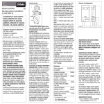
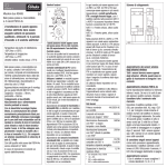
GB
22 001 601 - 1
.
22 002 601 - 1
Switching relays
ER12-001-8..230 V UC,
ER12-002-8..230 V UC
ER12-001:
1 change over contact potential free
16 A/250 V AC.
Safe disconnection to VDE 0106, Part 101;
therefore, these devices can also be used as
coupling relays.
ER12-002:
2 change over contacts potential free
16 A/250 V AC.
Incandescent lamp load up to 2000 W.
No standby loss.
Modular device for DIN-EN 60715 TH35
rail mounting.
1 module = 18 mm wide, 58 mm deep.
State-of-the-art hybrid technology combines
advantages of nonwearing electronic control
with high capacity of special relays.
Universal control voltage 8 to 230 V UC.
Low switching noise. Contact position
indicator with LED.
Integrated free-wheeling anti-surge diode
(A1= +, A2 = -).
By using a bistable relay coil power loss
and heating is avoided even in the on mode.
The relay contact can be open or closed
when putting into operation. It will be
synchronised at first operation.
Typical connections
ER12-002
Technical Data
8..230 V UC
Control voltage
Rated switching capacity
16A /250V AC
2000 W
Incandescent lamp load and
halogen lamp load1) 230 V
1000 VA
Fluorescent lamp load with KVG
in lead-lag circuit or non compensated
500 VA
Fluorescent lamps with KVG
shunt-compensated or wih EVG
Compact fluorescent lamp with
EVG and energy saving lamps
Standby loss (activ power)
1)
2)
_ 70 A /
I on <
10 ms 2)
_
For lamps with 150 W max
For electronic ballast gears a 40fold inrush
current has to be calculated. For steady loads of
1200 W use the current-limiting relay SBR12.
!
The strain relief clamps of the
terminals must be closed, that
means the screws must be tightened
for testing the function of the device.
The terminals are open ex works.
Warning !
Only a trained electrician may install this
equipment, otherwise there is a risk of fire
or electric shock.
ER12-001
01/2009 Specifications subject to change.