1
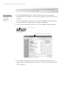
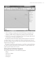
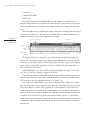
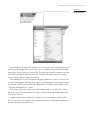
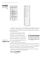
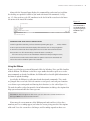
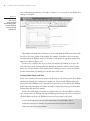
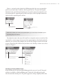
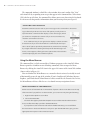
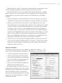
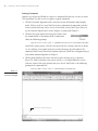
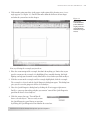
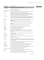
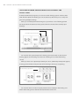
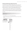
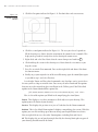
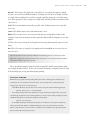
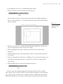
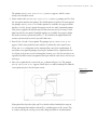
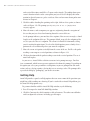
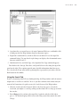
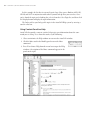
Chapter 1 AL Getting Familiar with AutoCAD RI If you are totally new to AutoCAD, you’ll want to read this chapter. It GH TE D MA TE provides an overview of AutoCAD’s layout and shows you what to expect when you start to use it. Even if you’ve had an AutoCAD class or used an older version of AutoCAD, you’ll find this chapter helpful because it covers the new AutoCAD interface. You’ll start by taking a tour of the AutoCAD window to get familiar with the menus and other components. You’ll then get a chance to try your hand at drawing, and in doing so, you’ll be introduced to the way AutoCAD’s commands work. You’ll also learn how to use the Zoom and Pan tools to help you get around in a drawing. And you’ll look at the ways you can view your drawing by using the layout feature. Finally, you’ll be introduced to the Help system for those times when you forget to have this book on hand. This chapter covers the following topics: Understanding the AutoCAD window ■■ Starting a drawing ■■ Panning and zooming to adjust your view PY RI ■■ Understanding the Layout view ■■ Understanding how command options work CO ■■ ■■ Getting help 2 ■ Chapter 1: Getting Familiar with AutoCAD Understanding the AutoCAD Window Autodesk has completely redesigned AutoCAD 2009’s interface. If you’ve used AutoCAD before, it will appear as though AutoCAD has completely changed. Don’t worry; the underlying program still behaves in much the same way as before. Through AutoCAD’s workspace feature, you can easily change AutoCAD’s interface to display the old, familiar toolbars that are seemingly missing from this latest version. You’ll get a chance to look at workspaces later in this chapter. In this section, you’ll look at AutoCAD’s newest interface options. The ↵ symbol in this book denotes the Enter key. Whenever you see it, press the Enter key, also known as the Return key. AutoCAD works like most other Windows-based graphics programs, but it also has a few quirks. This section gives you an overview of AutoCAD’s layout. Although many elements will be familiar, a few will be new to you. To start, you’ll see the two ways that AutoCAD displays a drawing. Then, for the rest of this chapter, you’ll focus on the 2D drawing environment. After installing AutoCAD, take the following steps to get to the 2D workspace: 1. Choose Start ➔ All Programs ➔ Autodesk ➔ AutoCAD 2009 ➔ AutoCAD 2009. (LT users will click AutoCAD LT 2009 in place of AutoCAD 2009 in the previous menu selection.) You can also double-click the AutoCAD 2009 icon on your Windows Desktop. The opening greeting, called a splash screen, appears momentarily; then, if this is a new installation, AutoCAD displays the Workspaces message box. This message box offers an option to select 2D Drafting & Annotation, 3D Modeling, or AutoCAD Classic. 2. Click 2D Drafting & Annotation. You’ll see the AutoCAD window with a blank default document named Drawing1.dwg, as shown at the top of Figure 1.1. If this is a new installation, you will also see the New Features Workshop window. If this happens, select Maybe Later, and then click OK. Au t o C A D 2 0 0 9 v e r s u s Au t o C A D 2 0 0 9 LT AutoCAD 2009 and AutoCAD 2009 LT are essentially the same programs, with some differencesboth large and small. The LT version has limited 3D capabilities and no 3D workspace. Customization features too are limited in the LT version. With the exception of the 3D features, you should be able to use the features discussed in this book when using AutoCAD 2009 LT. Understanding the AutoCAD Window ■ 3 Figure 1.1 Quick Access Toolbar InfoCenter Menu Browser Ribbon Drawing area UCS Command window Status bar In some installations, you might see a Startup dialog box. If this happens to you, click Cancel, and AutoCAD will display the blank default document. 3. The default document appears to be an empty 2D space. You’ll also see a special tool palette, called the Ribbon, along the top, as shown in Figure 1.1. This is a set of 2D drafting and annotation tools that gives you ready access to the most common drafting functions. If this is a completely new installation, you might see the Autodesk Impressions toolbar in the middle of the AutoCAD window. Autodesk Impressions, an adjunct program to AutoCAD, enables you to edit your drawings using tools similar to those found in Adobe Illustrator. You can close this toolbar; I will not discuss this Autodesk product in this book. If you are using AutoCAD 2009, try the following exercise to see how to get to the 3D Modeling workspace (this workspace is not available in AutoCAD 2009 LT): 1. In the lower-right corner of the AutoCAD window, you’ll see a gear-shaped icon. This is the Workspace Switching tool. Click it to open a list that shows 2D Drafting & Annotation, 3D Modeling, and AutoCAD Classic. AutoCAD when opened into a 2D Drafting & Annotation workspace 4 ■ Chapter 1: Getting Familiar with AutoCAD If you’re feeling adventurous, you can go to Chapter 6 to find out more about AutoCAD’s new 3D tools. LT users will not have the 3D functions. 2. Select 3D Modeling from the list. (Notice that this list contains the same three options found in the Workspaces message box that appears in step 1 of the previous procedure.) The current default file, Drawing1.dwg, is set up for 2D drafting, but you can open a new file by using a file template already set up for 3D modeling. 3. On the Quick Start menu bar, click New. The Select Template dialog box appears. Click New in the Quick Start menu bar The Select Template dialog box appears 4. Select acad3D.dwt from the list, and click Open. A new file, called Drawing2.dwg, appears. Notice that this drawing is in a 3D space. You’ll learn more about 3D modeling in Chapter 6. Understanding the AutoCAD Window 5. Click the Workspace Switching tool, and click 2D Drafting & Annotation in the Workspaces toolbar. You’ll be working in this workspace for most of this book. 6. Exit the 3D Drawing2.dwg file by clicking the Close icon in the upper-right corner of the drawing area. The Close icon looks like an X. Even though the default 2D file looks completely different from the new 3D file you created by using the acad3D.dwt template, they really are basically the same. They just have different display settings turned on. You can learn more about the different ways to display drawings in Chapter 6. You now have AutoCAD set up for 2D drawing, so you’ll take a more detailed look at the AutoCAD window. You’ll find that, for the most part, it is a typical Windows-style graphics program window with a few twists. Getting to Know the Window Components The AutoCAD window offers several controls to the program: • Ribbon • Quick Access Toolbar • Menu Browser • Drawing area ■ 5 6 ■ Chapter 1: Getting Familiar with AutoCAD • Status bar • Command window • InfoCenter Figure 1.2 Your AutoCAD window should look like the earlier Figure 1.1, which shows the default configuration for a new AutoCAD installation. Since AutoCAD is so easy to customize, you might not see exactly the same layout, but the basic components should be there. AutoCAD 2009 offers the Ribbon that contains most of the common functions you’ll need to use (see Figure 1.2). The Quick Access Toolbar offers the most commonly used Windows functions, such as Save, Undo, Redo, and Print. Quick Access Toolbar The Ribbon and its components InfoCenter Ribbon tabs Ribbon panels Ribbon panel title bars The Ribbon contains several panels, each of which contains tools for drawing and editing. The set of panels changes depending on which Ribbon tab is selected. The Ribbon panels can be moved with a click and drag of their title bars, and the entire Ribbon can be set up to stay hidden until you need to use it. You’ll learn more about these features a bit later in this chapter. When Ribbon panels are away from the edge of the window and appear “free floating,” they are said to be floating, as opposed to docked. If you click the AutoCAD logo in the upper-left corner of the window, you open the Menu Browser, which gives you a more conventional menu structure for finding AutoCAD functions with a few additional features (see Figure 1.3). At the top of the Menu Browser, you see the Search tool. This enables you to find a specific tool by name just by typing the name into the search input box. At the bottom of the Menu Browser, you have three options: Recent Documents, Open Documents, and Recent Actions. If you point to Recent Documents, the panel to the right lists the most recent files you’ve opened. Each file has a pushpin icon to the right, enabling you to lock the item in the list. If you point to Open Documents, you’ll see a list of documents that are currently open in AutoCAD. The Recent Actions option lists the last few actions you’ve taken using the Menu Browser. You can repeat an action by selecting it from the list. Understanding the AutoCAD Window ■ 7 Figure 1.3 Click the AutoCAD icon to open the Menu Browser In the middle of the AutoCAD window is the drawing area where you’ll do your actual drawing. At the bottom of the screen is the status bar, which provides information about many of the settings you’ll use in AutoCAD. The status bar also offers controls over many of the different drawing modes in AutoCAD. Just above the status bar is the command window, which is almost unique to AutoCAD. The command line is a text window that displays commands as you use them, as well as your keyboard input. Messages often appear here that prompt you to perform a step in a command. You’ll learn more about the command line a bit later in this chapter; see the “Using the Command Line” section. In the upper-right corner of the AutoCAD window you’ll see the InfoCenter. This is where you can get help about AutoCAD feature or find current information about AutoCAD on the Internet. Another unique item in AutoCAD’s window is the set of tool palettes shown in Figure 1.4. You can use these palettes to keep your favorite tools and drawing components in one convenient place for quick access. The Menu Browser 8 ■ Chapter 1: Getting Familiar with AutoCAD Figure 1.4 The Properties palette (at left) and the tool palettes (at right) Tool palettes Properties palette The Properties palette shown on the left and the AutoCAD tool palettes shown on the right of Figure 1.4 might not appear in your AutoCAD window by default, but you can open the tool palettes by clicking the View tab in the Ribbon and selecting Tool Palettes from the Palettes panel. The drawing area, the status bar, and the View tab command line work together to give you feedback while you create and edit your drawing. As you move your cursor over the drawing area, you’ll see the cursor appear as a crosshair cursor. If you click the drawing area, a pair of numbers and a selection window appear. Click again, and Tool palettes the selection window disappears. With the crosshair cursor, you can point to portions of the drawing area, and the numeric display, known as the Dynamic Input display, tells you your XY coordinate within the drawing area. The selection window lets you select objects in the drawing area. You’ll learn more about coordinates in AutoCAD in Chapter 2, and you’ll look at selection windows a bit later in this chapter. If you don’t see the Dynamic Input display, go to the status bar at the bottom of the AutoCAD window, and click the Dynamic Input tool. Understanding the AutoCAD Window Along with the Dynamic Input display, the command line and status bar just below the drawing area provide feedback as you work with AutoCAD commands (see Figure 1.5). You can also see the XY coordinate in the far left of the status bar in the lowerleft corner of the AutoCAD window. Command line Figure 1.5 The status bar and the command line work with the drawing area to give you feedback as you draw. Coordinate readout Co n t r o ll i n g t h e S tat u s Ba r D i s pl ay To the far right of the status bar, you’ll see a downward-pointing triangle, or ■ 9 arrow; click this arrow to open a menu that controls the display of the status bar. You can also just right-click in a blank area of the status bar to display this menu. You use this menu to turn the items in the status bar on or off. A check mark by an item indicates it is currently on. If for some reason you do not see all the buttons mentioned in the preceding discussion, check this menu to make sure that all the status bar options are turned on. Note that the LT version does not have an Otrack option in the status bar. Using the Ribbon If you’ve used the latest version of Microsoft Office for Windows Vista, you’ll be familiar with the Ribbon. The Ribbon is a bit like a super toolbar that offers quick access to the most commonly used tools. In addition, the Ribbon offers a lot of helpful information in the form of expanded tooltips. Specifically, the Ribbon is a collection of tools that invoke commands. These tools are grouped into several tabs. Each tab contains a set of panels, and each panel contains a set of icons representing tools and showing their function (see the earlier Figure 1.2). The tools also offer tooltips that provide a lot of information, including a description that helps you understand what the icons represent. If the Ribbon does not appear on the screen, you can click in the command window and then type ribbon↵ to restore it to the window. If you move the cursor onto one of the Ribbon panel tools and leave it there for a moment, you’ll see a tooltip appear just below the cursor, giving you a brief description of the tool. Leave the cursor there a bit longer, and the tooltip expands to show even 10 ■ Chapter 1: Getting Familiar with AutoCAD Figure 1.6 more information on how to use the tool (see Figure 1.6). As a new user, you’ll find these tooltips very helpful. A tooltip showing the name of the tool, a brief tutorial-like graphic, and the command name associated with the tool Tool name Description/tutorial Keyboard command equivalent Context-sensitive help Throughout the book, when I ask you to select a tool from the Ribbon or from a toolbar, I’ll use the name shown in the tooltip. For example, if you hover your cursor over any icon tool in the Ribbon, you’ll see the name of the tool at the top of the tooltip that appears (as shown in Figure 1.6). In most cases, you’ll be able to guess what each tool does by looking at its icon. The icon with an arc in the Draw panel of the Ribbon, for instance, indicates that the tool draws arcs; the one with the circle shows that the tool draws circles; and so on. But for further clarification, the tooltip gives you the name of the tool. Finding Hidden Panels and Tools In the next section, you’ll start to work in the drawing area by drawing some lines. Before you do that, though, take a moment to examine the left part of the Ribbon, where the Draw panel of the Ribbon resides. You will be instructed to use the tools in this Ribbon panel frequently throughout this book, so it will be helpful for you to get a feel for their arrangement and what they contain. Besides the visible tools, a few tools are hidden from view. Click the Blocks and Reference tab just above the Ribbon. The row of Ribbon panels changes to a new set of panels. Click the Home tab above the Ribbon to return to the previous set of panels. As you work through exercises in this book, I’ll abbreviate the name of the Ribbon tabs to simplify the instructions. For example, I’ll say “On the Home tab’s Draw panel” to refer to the Draw panel on the Home tab of the Ribbon. Understanding the AutoCAD Window If you see a triangle on the right side of a Ribbon panel title bar, you can expand the panel to reveal more tools. To do this, click the panel title bar. The panel will expand downward. Once you click in the drawing area, the panel returns to its normal view. If you want to lock the expanded panel so that it stays open, click the pushpin icon on the right side of the expanded panel’s title bar. Click the title bar to expand the panel Pushpin icon From now on, when you see the term expanded panel, you should expand the Ribbon panel by clicking the panel’s title bar. You might also notice that some of the tools have triangular arrows next to them. You can click these arrows to open flyout menus that contain options related to the tool with which they are associated. For example, you can click the triangle next to the Circle tool to open a flyout that offers different ways to draw a circle. You’ll get a chance to use these features in Chapter 3. Click the triangular arrow to open the flyout Switching to Floating Ribbon Panels If you find that you use one particular Ribbon panel a lot, you can “tear off” the panel and have it available as a floating Ribbon panel. To do this, click and drag the panel title bar toward the drawing area. The panel’s appearance changes slightly to offer some ■ 11 12 ■ Chapter 1: Getting Familiar with AutoCAD Figure 1.7 A Ribbon panel in its floating appearance, showing its controls controls (see Figure 1.7). These controls disappear when you are not pointing inside the panel, but they reappear when you hover over the panel with your cursor. Tooltips appear when you hover over the Close Panel Send to Ribbon controls, and they describe what each control Options does. The last control, Toggle Orientation, is Toggle Orientation a little misleading because it controls the display of the title bar. Getting Familiar with the Drawing Area As you might imagine, the drawing area in the middle of the AutoCAD window is the space where you’ll be spending a lot of time. It pays to get a feel for how it behaves early on. As your introduction to the drawing area, try the following exercise: 1. Move the cursor around in the drawing area. As you move the cursor, notice that the coordinate readout in the status bar gives the X and Y coordinates and adds the Z coordinate. 2. Click in the middle of the drawing area. You have just selected a point. Move the cursor, and a rectangle follows. This is a selection window; if any objects appear in the drawing area, you can select them for editing. A coordinate display appears at the cursor, showing your coordinates in an X, Y format. Also notice the words Specify opposite corner in the Dynamic Input display. This tells you that you have started a selection window and you need to select the opposite corner for the window. 3. Move the cursor a bit in any direction; then click again. Notice that the selection window disappears. Had there been objects within the selection window, they would be selected. This is similar to the way the cursor behaves on the Windows Desktop; however, in Windows, you have to drag the cursor to create a selection window. 4. Try selecting several more points in the drawing area. Notice that as you click, you alternately start and end a selection window. As you click the drawing area, you might notice that, depending on whether you click to the right or to the left of the preceding point, the selection window displays a different color. If you click from left to right, the selection window appears blue. From right to left, it’s green. These colors indicate a different mode of selection, which you’ll learn about in Chapter 4. If you right-click, a shortcut menu appears. Just as with most other Windows applications, a right-click frequently opens a menu that contains options that are context sensitive. This means that the contents of the shortcut menu depend on where you right-click as well as on the command that is active at the time of your right-click. You’ll learn more about these options as you progress through the book. For now, if you happen to open this menu by accident, press the Esc key to close it. Understanding the AutoCAD Window Finally, as with any window, you can expand the drawing area or contract it into a smaller window by clicking the Restore Down icon in the upper-right corner of the drawing area. When the drawing area is in the Restore Down position, it appears as a separate window within the AutoCAD window. You can then resize the window to any rectangular shape you need. This is helpful when you have multiple AutoCAD drawing files open. To maximize a drawing to fill the AutoCAD window, double-click the drawing window title bar. Checking the UCS Icon The UCS icon is the L-shaped icon you see at the lower-left corner of the drawing area (shown earlier in Figure 1.1). It helps you see your orientation at a glance by pointing to the positive X and Y directions. UCS stands for user coordinate system. That name is a hint that you can create and use other coordinates besides the default one that exists in new drawings. By default, the X direction is from left to right, and the Y direction is from bottom to top; but with AutoCAD you can alter your view orientation as well as include additional coordinate systems that can be oriented in different directions. The UCS icon is especially helpful when you start to use these other coordinate systems and display modes, but right now, just be aware that it is there to help you get your bearings. You might notice a small square at the base of the UCS icon. This square tells you that you are in the world coordinate system, which is the base coordinate on which other coordinate systems can be built. You’ll learn more about the UCS in Chapter 5. Using the Command Line The horizontal window at the bottom of the AutoCAD window is called the command window. Besides the drawing area, this is where you can get feedback from AutoCAD. As you work in AutoCAD, the command activity appears in the bottom line of the command window and scrolls upward. When AutoCAD is waiting for input, you’ll see the word Command: at the bottom of the command window. This is the command prompt. As you click a point in the drawing area, you’ll see the message Specify opposite corner in the command line. Simultaneously, a selection window appears in the drawing area. Click another point without selecting anything; the selection window disappears, and the command prompt returns. You’ll want to pay close attention to the command window as you start using AutoCAD because it tells you what AutoCAD expects you to do. It also lists information when you query AutoCAD for certain types of information, which you’ll learn about in later chapters. In addition to getting feedback from the command window, you’ll also see the command prompt at the cursor whenever you have the Dynamic Input display turned on. Minimize Restore Down Close ■ 13 14 ■ Chapter 1: Getting Familiar with AutoCAD The command window is a little like a chat window when you’re online. You “chat” with AutoCAD by responding to messages that appear in the command line. When AutoCAD asks for specific data, the command line allows you to enter data using the keyboard. It is also an area that provides information about your drawing when you request it. “ C h at t i n g ” w i t h Au t o C A D AutoCAD communicates its needs to you in messages in the command line. These messages often tell you what to do next or offer options, usually shown in square brackets. Commands often display a series of messages, which you answer to complete the command. If you aren’t sure what to do, check the command line for clues. As an additional aid, you can right-click to display a context-sensitive shortcut menu. If you are in the middle of a command, this menu pro vides a list of options specifically related to that command. For example, if you right-click before selecting the first point for the Rectangle com mand, a menu appears, offering the same options that are listed at the command prompt, plus some additional options. Using the Menu Browser The command line is a little unusual for a Windows program, so the AutoCAD Menu Browser provides a familiar means of finding commands. You can open the Menu Browser by clicking the AutoCAD icon in the upper-left corner of the AutoCAD window (shown earlier in Figure 1.3). You can think of the Menu Browser as a menu bar that is oriented vertically, instead of horizontally across the top of the window. If you’re familiar with Windows Internet Explorer, you’ll find that the Menu Browser behaves much like the Favorites list. In fact, the Menu Browser behaves like the tree view found in many navigation schemes. W h at H a p p e n e d t o t h e M e n u B a r ? Earlier versions of AutoCAD had a horizontal list of options called a menu bar across the top of the window. If you prefer to use the menu bar, you can turn it on by doing the following : 1. Right-click the Q uick Access Toolbar. 2. Select Show Menu Bar. The menu bar appears just below the Q uick Access Toolbar. Note that the menu bar does not offer the tooltips you find in the Menu Browser. If you prefer to use the menu bar rather than the Menu Browser, you can still follow the instructions in this book. Whenever I ask you to open the Menu Browser, just go to the appropriate menu option in the menu bar instead. Understanding the AutoCAD Window In the Menu Browser, you’ll see many of the standard Windows menu options, such as File, Edit, Window, and Help, as well as a few that are specific to AutoCAD. Another Menu Browser feature is the command description that appears as a tooltip whenever you hover over a menu option. These descriptions often give enough detailed information to get you started using the option. Try the following to see the tooltips firsthand: 1. Open the Menu Browser, and click Modify. The list of items that appears includes the commands and settings that let you control the way AutoCAD displays your drawings. 2. Move the cursor down the list of menu items. As you highlight each item, notice that a tooltip appears. These tooltips help you choose the menu option you need and in many cases give a kind of mini-tutorial on how to use the option. These tooltips are the same as the ones you see with the Ribbon panel tools. Near the bottom of the tooltip, you’ll see a single word in capital letters. This is the keyboard command equivalent to the highlighted option in the menu (shown earlier in Figure 1.6). If you prefer, you can actually enter these keyboard commands to start the tool or menu item you have highlighted. You don’t have to memorize these command names, but knowing them will help you later if you want to customize AutoCAD. 3. Some of the menu items won’t show a tooltip but will have arrows to their left. This means the menu option has additional choices. For instance, click the Object option, and you’ll see the list of options expand below the Object option. Click the Object option again, and the list closes. Opening Dialog Boxes You might have noticed that other menu options are followed by an ellipsis (…). This indicates that the option displays a dialog box, as the following exercise demonstrates: 1. Click the Tools option in the Menu Browser. 2. Click the Options item at the bottom of the menu to open the dialog box (you might have to use the scroll bar to the right of the Menu Browser to get to the bottom of the list). 3. After you’ve taken a look at the Options dialog box, close it by clicking Cancel. The Options dialog box is like the Preferences dialog box in other programs. In it, you can find most of the general settings that affect AutoCAD’s behavior. Numerous settings are divided into tabs across the top of the dialog box. The Options dialog box is one of many dialog boxes available through the menu bar. ■ 15 16 ■ Chapter 1: Getting Familiar with AutoCAD Starting Commands Another type of item you’ll find in a menu is a command that directly executes an AutoCAD operation. Try this exercise to explore a typical command: 1. Click the Dynamic Input tool in the status bar to turn off Dynamic Input display mode. When it is off, it is gray. You’ll start your exploration of commands with this feature turned off so you can get a clear view of your activity. You’ll get a chance to try the Dynamic Input feature in later chapters, starting with Chapter 2. 2. Click the Rectangle tool in the Draw panel. Notice that the command line at the bottom of the window now shows the following prompt: Specify first corner point or [Chamfer/Elevation/Fillet/Thickness/Width]: AutoCAD is asking you to select the first corner for the rectangle, and also, in brackets, it is offering a few options that you can take advantage of at this point in the command. Don’t worry about those options right now. You’ll have an opportunity to learn about command options in Chapter 2. 3. Click a point roughly in the lower-left corner of the drawing area, as shown in Figure 1.8. Now as you move your cursor, you’ll see a rectangle follow the cursor with one corner fixed at the position you just selected. You’ll also see the following prompt in the command line: Figure 1.8 Specify other corner point or [Area/Dimensions/Rotation]: Selecting the first point of a rectangle Click here to start the rectangle. Understanding the AutoCAD Window 4. Click another point anywhere in the upper-right region of the drawing area. A rectangle appears (see Figure 1.9). You’ll learn more about the different cursor shapes and what they mean later in this chapter. ■ 17 Figure 1.9 Once you’ve selected the first point of the rectangle, you’ll see a rectangle follow the motion of your mouse. Next, try deleting the rectangle you just drew: 1. Place the cursor on top of the rectangle, but don’t do anything yet. Notice that as you pass the cursor over the rectangle, it is highlighted. In a crowded drawing, this highlighting can help you determine exactly what will be selected when you click an object. 2. With the cursor on the rectangle and the rectangle highlighted, click the rectangle. The rectangle is selected, and the Quick Properties dialog box opens. This dialog box gives you access to the properties of the selected object. 3. Close the Quick Properties dialog box by clicking the X in its upper-right corner. You’ll see a message box asking whether you want to “turn off the Quick Properties panel for all future selected objects.” 4. Click the answer that says “Turn off for all future selected objects.” You can easily restore the Quick Properties panel feature at any time by clicking the Quick Properties Panel tool in the status bar. You’ll learn more about the Quick Properties panel in Chapter 4. 18 ■ Chapter 1: Getting Familiar with AutoCAD 5. The rectangle is still selected, so press the Delete key to delete it. This removes the rectangle from the drawing. In step 1, AutoCAD shows you exactly what the cursor is pointing to by highlighting objects that will be selected with the next click. When drawing and erasing the rectangle, you were exposed to the most common processes you need to know about to work in AutoCAD: you selected a command from the menu bar, and then you selected points in the drawing area while following the messages in the command line. Commands from the toolbars work in the same way, as you’ll see next. U n d e r s ta n d i n g t h e Co mm a n d -To o l- O p t i o n R e l at i o n s h i p One of AutoCAD’s greatest assets is its ability to adjust to your way of performing tasks. If you prefer using toolbars, you can gain access to nearly all the AutoCAD functions through toolbars. If you prefer using options from a menu bar, again, you can perform most of what you need through them. And the Ribbon offers the most commonly used functions in AutoCAD. Experienced users know how to use the command line and know nearly all the commands by heart. The AutoCAD commands are really at the heart of its operations. Menu bar options, the Ribbon, and the toolbar buttons are really just different ways to invoke AutoCAD commands. When you click a toolbar button or a menu option, you are really initiating a command through AutoCAD’s menu system, sometimes with predetermined options already selected. In fact, if you watch the command line as you click a menu option or toolbar button, you’ll see that the messages in the command line are the same regardless of where you invoked the command. For this reason, I’ll often intermix the terms tool, option, and command, because at a practical level they are really all the same. Just be aware that menu options and toolbar buttons invoke commands. Using Other Toolbars If you are familiar with earlier versions of AutoCAD, you’ll remember that toolbars were the primary method for using the many AutoCAD drawing and editing tools. The toolbars are still available and can offer a quick way to get to the tools you need. Table 1.1 describes the toolbars that are available in AutoCAD. Like the floating Ribbon panel, a toolbar will display its Close icon (the X in the upper-right corner) when you hover over the toolbar with your cursor. O therwise, the Close icon will be hidden. Understanding the AutoCAD Window Command ■ 19 Table 1.1 Description 3D Navigation CAD Standards Tools for controlling 3D views (not available in LT). Tools for checking the layer, dimension, and text styles against standards you have created (not available in LT). Camera Adjustment Tools for controlling camera objects. Dimension Commands for helping you dimension your drawings. Many of these commands are duplicated in the Dimension drop-down menu. See Chapter 10. Draw Commands for creating common objects, including lines, arcs, circles, curves, ellipses, and text. This toolbar appears in the AutoCAD window by default. Many of these commands are duplicated in the Draw drop-down menu. Draw Order Commands for arranging the order of overlapping objects. If an object covers another object that you need visible, you can use the Draw Order toolbar to “move” an object behind another or to the back of a set of objects (not available in LT). Find Text Input box and search text tool to help you locate text strings in a drawing. Inquiry Commands for finding distances, point coordinates, object properties, mass properties, and areas. Insert Commands for importing other drawings, raster images, and OLE objects. Layers Drop-down list and tools, just below the Standard toolbar, for controlling layer properties. Layers II Additional tools for managing layers (formerly Express Layer tools). Layouts Tools for setting up drawing layouts for viewing, printing, and plotting. Lights Tools for adding and controlling lights in 3D models. Mapping Tools for adding texture maps in 3D models. Modeling Tools for creating and editing 3D objects. Modify Commands for editing existing objects. You can move, copy, rotate, erase, trim, extend, and so on. Many of these commands are duplicated in the Modify dropdown menu. Modify II Commands for editing special complex objects such as polylines, multilines, 3D solids, and hatches. Multileader Tools for adding leader notes to your drawing. Object Snap Tools for selecting specific points on objects, such as endpoints and midpoints. See Chapter 3. Orbit Tools for controlling 3D views. Properties Commands for a set of drop-down lists and tools for manipulating the properties of objects. This toolbar is ordinarily docked to the right of the Layer toolbar, just below the Standard toolbar. Refedit Tools for making changes to symbols or background drawings that are imported as external reference drawings (not available in LT). Reference Commands for controlling the cross-referencing of drawings. See Chapter 8. Render Commands for operating AutoCAD’s rendering feature (not available in LT). Solids Editing Command for editing 3D solids (not available in LT). See Chapter 6. Standard The most frequently used commands for view control, file management, and editing. This toolbar is ordinarily docked below the menu bar. Standard Annotation An abbreviated version of the Standard toolbar. Styles Tools for controlling style options such as text styles and dimension styles. Text Tools for creating and editing text. See Chapter 9. UCS Tools for setting up a plane on which to work. This is most useful for 3D modeling, but it can be helpful in 2D drafting as well. See Chapter 6. continued AutoCAD Toolbars 20 ■ Chapter 1: Getting Familiar with AutoCAD continued Command Description UCS II View Tools for selecting from a set of predefined user coordinate systems. Tools for controlling the way you view 3D models. See Chapter 6 for more on 3D views. Tools for creating and editing multiple views of your drawing. See Chapter 6 for more about viewports. Tools for controlling the way 3D models are displayed. Tools for controlling motion through a 3D model. Tools for accessing the Web. Tools for managing workspaces. Commands for navigating your drawing. Viewports Visual Styles Walk and Fly Web Workspaces Zoom Opening toolbars is fairly simple, but unless you know where to look, you might never find them. The following steps show you how to open the Draw toolbar: 1. To open the Draw toolbar, right-click the Quick Access toolbar in the upper-left corner of the AutoCAD window. A shortcut menu of options appears. 2. On the shortcut menu, choose Toolbars ➔ AutoCAD ➔ Draw. The Draw toolbar appears in its docked position at the left side of the AutoCAD window. (Again, docked just means the toolbar is merged with the border of the AutoCAD window to keep it out of the drawing area.) 3. You can “undock” a toolbar by clicking and dragging the toolbar’s grab bar. The grab bar is the dotted area you see at the top or left end of the toolbar. (Again, the toolbar then is called a floating toolbar and shows its title bar.) In its floating position, you can click the X in the upper-right corner of the Draw toolbar to close it. You can dock toolbars at the top, bottom, or sides of the AutoCAD window to keep them out of the drawing area. If you do not want the toolbar to dock but instead want it to appear “floating” near the border of the AutoCAD window, you can press the Ctrl key before you click and drag the toolbar into position. This prevents toolbars from automatically falling into a docked position. AutoCAD remembers your toolbar arrangement between sessions. When you exit and then reopen AutoCAD later, the AutoCAD window appears just as you left it. Starting a Drawing Starting a Drawing What you do to start a new drawing in AutoCAD is a little different from what you do in other programs, so let’s create a new file to see how it’s done: 1. From the Menu Browser, choose File ➔ Close to close the current file. When the message box appears asking you to save changes, click No. Notice that the toolbars disappear and that the AutoCAD drawing window appears blank when no drawings are open. 2. From the Menu Browser, choose File ➔ New to open the Select Template dialog box. 3. Select the acad.dwt template file, and then click Open to open a blank drawing window. 4. To give your new file a unique name, choose File ➔ Save As to open the Save Drawing As dialog box. 5. Enter My First Drawing. As you type, the name appears in the File Name text box. By default, the file will be saved in the My Documents folder. 6. Click Save. You now have a file called My First Drawing.dwg, located in the My Documents folder. Of course, your drawing doesn’t contain anything yet. You’ll take care of that next. The acad.dwt template file you selected in step 3 is really just an AutoCAD drawing file that has been set up with standard settings. AutoCAD uses those settings to create a new file. As you saw in the Select Template dialog box, you can choose from several such templates. The new file you just created shows a drawing area roughly 31 units wide by 13 units high. The units can be inches, meters, or millimeters. You determine what the units are equivalent to through the Drawing Units dialog box, which you will learn about in Chapter 2. The drawing area you’re presented with initially is your workspace, although you’re not limited to the 75 by 45–unit area in any way. No visual clues indicate the size of the area, so to check the area size for yourself, move the crosshair cursor to the upper-right corner of the screen, and observe the value in the coordinate readout in the lower-left corner of the AutoCAD window. This is the standard AutoCAD default drawing area for using the acad.dwt drawing template for new drawings. The coordinate readout won’t show exactly 75 units by 45 units, because the proportions of your drawing area are not likely to be exactly 7.5 by 4.5. Factors such as the size and resolution of your display and the shape of the AutoCAD window affect the dimensions of the drawing area. ■ 21 22 ■ Chapter 1: Getting Familiar with AutoCAD S w i tch i n g B e t w e e n O pe n D r aw i n g s a n d t h e M o d e l a n d L ayo u t V i e w s As with most Windows programs, you can have several drawings open at one time. AutoCAD offers the Quick View Drawings tool in the status bar, with which you can easily navigate among multiple drawings. When you click the Quick View Drawings tool, you will see a row of drawing preview p anels just above the status bar. These panels show the contents of the currently open drawings. Closes file in the preview panel Saves file in the preview panel You can then click a preview panel of a drawing you want to switch to ; the selected drawing appears in the drawing area. Click in the drawing area to make that drawing c urrent. When you hover over a preview panel with your cursor, additional preview panels appear, showing you the model and layout views of the drawing to which you are pointing. Model and Layout previews You can then click in a model or layout preview to have it display in the drawing area. Click in the drawing area to make the selected view the current one. Starting a Drawing ■ 23 Next, try drawing a couple of objects just to get comfortable with drawing in AutoCAD. In the following exercise, you’ll draw a rectangle; then you’ll add a circle: 1. Click the Rectangle tool in the Draw panel. Remember that you can use the tooltips to help you locate a tool. You can also choose Draw ➔ Rectangle from the Menu Browser. 2. Click a point in the lower left of the drawing area, as shown in Figure 1.10. Don’t worry about the exact location. You’re just practicing right now. After clicking, you’ll see that one corner of the rectangle follows the cursor. Drawing a circle Click here for the center of the circle Click here to “fix” the circle’s radius Click here to start the rectangle Figure 1.10 Then click here to complete the rectangle 3. Click a point in the upper right of the drawing area, as shown in Figure 1.10. Again, it’s not important if you don’t pick the exact location. The rectangle is now in place. Now add a circle to the drawing: 1. Click the Circle tool in the Draw panel. 2. Click the location shown in Figure 1.10 to place the center of the circle. Now as you move the cursor, a circle appears whose radius follows the location of the cursor. 3. Click another point as shown in Figure 1.10 to “fix” the circle’s radius in place. If you prefer, you can enter an exact radius value for a circle instead of clicking another point to “fix” the circle radius. You now have a circle and a rectangle. As you can see, you create objects by placing key points of their geometry within the drawing area. For the rectangle, it was two corners; for the circle, it was the center and a location on the perimeter. Once you’ve placed objects in the drawing, you can use a variety of tools to edit them. In later chapters, you’ll learn more about those editing tools. In the following section, you’ll learn how to get around in your drawing. 24 ■ Chapter 1: Getting Familiar with AutoCAD W h e n Yo u N e e d to U n d o The AutoCAD User Group International (AUGI) has conducted a survey to identify the most commonly used features in AutoCAD. The group found that the Undo feature and the Esc key were at the top of the list. Everyone makes mistakes, and it would be impossible to get any work done if it weren’t for these two features. But Undo and the Esc key are just two of a set of features you can use to reverse something you have done. If you find you’ve done something unintentionally, you can use the following options to get out of trouble: Backspace If you make a typing error, press the Backspace key to back up to your error, and then reenter your command or response. Esc When you need to exit a command or a dialog box quickly, without making changes, just press the Esc key in the upper-left corner of your keyboard. U↵ If you accidentally change something in the drawing and want to reverse that change, click the Undo tool (the left-pointing curved arrow) in the Standard toolbar. You can also enter U↵ at the command prompt. Each time you do this, AutoCAD undoes one operation at a time, in reverse order. The last command performed is undone first, then the next-to-last command, and so on. The prompt displays the name of the command being undone, and the drawing reverts to its state before that command. If you need, you can undo everything back to the beginning of an editing session. Undo If you decide that you want to back up a few steps in an operation you just performed, you can use the Undo tool (the left-pointing curved arrow) on the Quick Access Toolbar. Each click of the Undo tool steps you back one operation. Redo If you accidentally undo one too many commands, you can redo the last undone command by clicking the Redo tool (the right-pointing curved arrow) on the Quick Access Toolbar. Or enter Redo↵. If you’ve used earlier versions of AutoCAD and are wondering where the Undo and Redo drop-down lists went, you can find them by opening the Standard toolbar. Right-click the Quick Access Toolbar, and select Toolbars ➔ AutoCAD ➔ Standard. The Undo and Redo drop-down lists enables you to be more specific about the point to which you undo or redo your work. Panning and Zooming to Adjust Your View Panning and Zooming to Adjust Your View One of the greatest features of AutoCAD is its ability to draw accurately through a wide range of scales. For example, you can draw a football field, zoom into a blade of grass, and draw its cell structure. With such a broad range of views to work with, you need to be familiar with AutoCAD’s view features. The Zoom and Pan commands are the most frequently used view features, so you’ll want to become familiar with them right away. If you have a typical mouse with a scroll wheel, you can use the wheel to zoom in and out of your drawing view. You can also use it to pan across your drawing. To zoom, scroll the wheel. To pan, click and drag the scroll wheel. You can obtain just about any view you need by using this method. You’ll also want to know about several other viewrelated tools. If you have a mouse that uses special drivers, you might not be able to use the wheel to control pans and zooms. Try the following exercise to see how the Zoom tool works: 1. Click the magnifying glass icon in the Home tab’s Utilities panel to open the Zoom flyout. 2. Select Window from the Zoom flyout. Click the Zoom flyout arrowhead, and select Zoom Window ■ 25 26 ■ Chapter 1: Getting Familiar with AutoCAD Figure 1.11 3. Click the first point indicated in Figure 1.11. You don’t have to be too accurate. Selecting a Zoom window Click this location first to start the Zoom window Then click this location 4. Click the second point indicated in Figure 1.11. The area you selected expands to fill the drawing area. Notice that the transition to the zoomed view is smooth. This helps you keep track of exactly where in the drawing the zoom occurs. 5. Right-click, and select Pan. Notice that the cursor changes to a hand icon . 6. Click and drag the cursor in the drawing area. Notice how the view moves as you drag the cursor. 7. Press Esc to exit the Pan command. You can also right-click and choose Exit from the shortcut menu. 8. Finally, to get your original view of the overall drawing, open the zoom flyout again as you did in step 1 and select Previous. Several other Zoom- and Pan-related commands exist, but those you’ve just tried are the ones you’ll use 90 percent of the time. You can try the other Zoom and Pan options that you saw in the magnifying glass icon flyout in the Utilities panel. You’ll also find options in the Zoom command-line options list: [All/Center/Dynamic/Extents/Previous/Scale/Window/Object] <real time>: Here is a list of the options you’ll find in the magnifying glass icon flyout: Extents This displays a view that encompasses all the objects in your drawing. This option ignores the limits of your drawing. Previous This displays the previous view, just as Undo does for the Zoom command. Realtime This is the default Zoom option. It displays a magnifying glass cursor. With this option, you can click and drag up or down to change your magnification in real time. You can right-click to access the other Zoom options, including Exit and Cancel. All This displays the area of your drawing defined by the drawing limits plus any part of your drawing that falls outside the limits. Panning and Zooming to Adjust Your View Dynamic This changes the display to an overall view. A rectangle also appears, which lets you select an area to which to zoom in. To change the size of the rectangle, click the rectangle. You can adjust the size of the rectangle and thus change the size of the zoom area. Click again to fix the rectangle size. Right-click, and choose Enter to zoom in to the selected area. Scale This lets you zoom in or out by a specific value. It allows you to enter a specific view scale. Center This allows you to center a location on the screen. Object This lets you select a view area based on the area occupied by an object. For example, if you want to zoom in so that a particular object fills the display area, use this option. In This is the same as using the Scale option and entering 2x to magnify your view two times. Out This is the same as using the Scale option and entering 0.5x to view twice the cur- rent view area. You can also start a zoom or pan by clicking the magnifying glass icon or hand icon in the status bar, or right-click and select Zoom or Pan at any time. You can right-click in the middle of a zoom to switch to pan and vice versa. You’ve just about completed your first look at AutoCAD. You’ll want to know about just a couple of other features. In the next section, I’ll introduce a display feature in AutoCAD that helps you set up your drawing for printing. Acc u r at e Pa n n i n g Realtime Pan is a great tool for quickly getting around in a drawing, but sometimes you need to pan in an exact distance and direction. A version of the Pan command lets you “nudge” your view to an accurate distance. In the Menu Browser, choose View ➔ Pan ➔ Point, and you’ll see the following prompt: Specify base point or displacement: This is the prompt you’ll see for the Move or Copy command, though in this case you’re not affecting the objects in your drawing. When you select a point at this prompt, you’ll see a rubber-banding line in conjunction with the next prompt: Specify second point: The rubber-banding line indicates the direction and distance of your pan. As with any other command that displays a rubber-banding line, you can select points to indicate distance and direction, or you can enter coordinates. This enables you to specify exact distances and directions to pan your view. ■ 27 28 ■ Chapter 1: Getting Familiar with AutoCAD Understanding the Layout View Aside from the command prompt, you’ve probably noticed that AutoCAD behaves like most other Windows programs. But in one of its features AutoCAD is a little different from other Windows graphics programs. Specifically, at the bottom of the AutoCAD window, you’ll see an icon that looks like a triangle over a grid. If you hover over the icon, you’ll see that it is labeled Layout1. Another icon to the left of Layout1 is called Model. The Model icon is currently active, telling you that you are in what is called model space. If you have followed the exercises in this chapter, you’ve been working in model space all along. Model space is the display you’ll use to do most of your drawing. It’s like your main workspace. Clicking the Layout1 icon opens a view that is like a page preview with the added advantage of enabling you to draw within the preview. This preview is called a paper space layout. Besides previewing your drawing, Layout1 also gives you control over the printed scale. You can have multiple paper space layouts for different printed versions of your drawing. For example, you can have one layout for an 8½ by 11–inch sheet and another layout for an 11 by 17–inch sheet. Or, if you use multiple printers, you can have a layout set up for each printer. The terms paper space and layout are often used interchangeably, which can cause a lot of confusion to new users. One way to think of these two terms is to say that “paper space is where you lay out your drawing.” It’s called paper space because it is where your drawing is translated into the paper shape, size, and layout of your drawing before you actually commit the drawing to paper. Another way to look at paper space layouts is to think of them as a drawing mock-up area. Using a paper space layout, you can set up multiple views of the drawing you create in model space. You can also add a title to your drawing and include borders or other graphic design features. Since paper space layouts are labeled with the “layout” prefix, as in Layout1, I’ll just use the term layout in this book. Understanding the Layout View ■ 29 Try the following exercise to see firsthand how layouts work: 1. Click the Layout1 icon at the bottom of the drawing area. The drawing area changes to show your drawing, plus some additional display elements, as shown in Figure 1.12. The Layout shows you how your drawing will look when it is printed. Click this outline, and press the Delete key 2. Move the cursor over the rectangle that immediately surrounds the rectangle and circle drawing that you created earlier in the chapter. 3. Click the highlighted rectangle, and then press the Delete key. Your drawing disappears. 4. Click the Model icon to return to model space. You’ll see that the objects you drew are still there. 5. Click the Undo tool in the Quick Access Toolbar twice to return to the Layout1 view and undo your deletion of the outer rectangle. The view of the rectangle and the circle returns. 6. Click the Model icon to return to the original drawing area. In step 3, your entire drawing disappeared when you deleted the outer rectangle. This is because that rectangle is really a viewport into the drawing you created in model space. When you are in a layout view, a viewport acts like a window into your drawing. By default, AutoCAD creates a single viewport to show your drawing, but you can have Figure 1.12 Your drawing as it appears in one of the Layout 30 ■ Chapter 1: Getting Familiar with AutoCAD multiple viewports of various sizes, each displaying different parts of your drawing. When you deleted that viewport, you essentially closed your view into your drawing in the model space, so your rectangle and circle disappeared from view. They didn’t really go anywhere. It’s just that your view of them was deleted. You might have also noticed that a Layout1 tool displays a white area over a gray background. This white area represents the area of the paper onto which your drawing will be printed. The white area also shows a dashed line close to its edge. This dashed line represents the printable area of your paper. The current default printer connected to your computer determines both the paper area and the dashed line. If you have a printer that accepts paper of different sizes, you can select a different sheet size, and the new sheet size will be reflected in the white area shown in the layout. You’ll learn how to control sheet sizes and layouts in Chapter 12. As you might guess, you use the layout to lay out your drawing for printing. You can print from the model space if you want, but you have much more control over your printer output from a layout. T u r n i n g o n t h e L ayo u t Ta b s AutoCAD can be set up to display layouts as tabs at the bottom of the drawing area. To turn them on, right-click the Model or Layout1 tool located at the bottom of the AutoCAD window, and then select Display Layout and Model Tabs. The tabs will appear just below the drawing area. To hide the tabs, right-click any tab, and select Hide Layout and Model Tabs. If you want to leave the tabs off, you can still switch from model space to a layout by clicking the Model or Layout1 tool. If you have multiple layouts, you can use tool just to the right of the Layout1 tool to select a layout. Understanding How Command Options Work Nearly every AutoCAD command offers a set of options shown at the command-line prompt. These options let you alter the behavior of a command to suit your current drawing. To see how command options work, and to get a feel for the drawing process in general, in this exercise you’ll draw an arc and then place it exactly in the inside corner of the rectangle: 1. Click the Arc tool in the Draw panel. Understanding How Command Options Work The prompt Specify start point changes to a crosshair cursor. of arc or [Center]: appears, and the cursor 2. If you examine this Specify start point of arc or [Center]: prompt, you’ll see that the start point contains two options. The default option is stated in the main part of the prompt: Specify start point. If other options are available, they appear within brackets, as in the [Center] option that appears in the Arc tool’s command prompt. This [Center] option tells you that you can also start your arc by selecting a center point instead of a start point. If multiple options are available, they appear within the brackets and are separated by slashes (/). The default is the option AutoCAD assumes you intend to use unless you tell it otherwise. 3. Enter C↵ to select the Center option. The prompt Specify center point of arc: appears. Notice that you had to enter only the C and not the entire word Center. When you see a set of options in the command line, note their capitalization. If you choose to respond to prompts by using the keyboard, these capitalized letters are all you need to enter to select that option. In some cases, the first two letters are capitalized to differentiate two options that begin with the same letter, such as LAyer and LType. 4. Now select a point for the center of the arc, as shown in Figure 1.13. The prompt Specify start point of arc: appears. You’ll also see a rubber-banding line from the center point you just selected to your cursor. Finally click here for the end point First click here for the arc center Then click here for the start point If you point directly to the right, you’ll see that the rubber-banding line snaps to an exact horizontal orientation, and you’ll see a tooltip appear at the cursor. This is a feature called polar tracking vector, and it helps you draw in exact horizontal Figure 1.13 Using the Arc command ■ 31 32 ■ Chapter 1: Getting Familiar with AutoCAD and vertical directions, much like a T square and a triangle. The tooltip shows your cursor’s location relative to the center point you just selected. It displays this information in what is known as a polar coordinate. You can learn more about polar coordinates in Chapter 2. 5. With the rubber-banding line pointing to the right, click to select a point, as shown earlier in Figure 1.13. The prompt Specify end point of arc or [Angle/chord Length]: appears. 6. Move the mouse, and a temporary arc appears, originating from the start point of the arc that you just selected and rotating about the center of the arc. As the prompt indicates, you now have three options. You can enter an angle, a chord length, or the endpoint of the arc. The prompt default, to specify the endpoint of the arc, lets you select the arc’s endpoint. The cursor is in Point Selection mode, telling you it is waiting for point input. To select this default option, you need only select a point on the screen indicating where you want the endpoint. 7. Move the cursor so it points vertically from the center of the arc. You’ll see the polar tracking vector snap to a vertical position, as shown in Figure 1.13. 8. Click any location with the polar tracking vector in the vertical position. The arc is now fixed in place. As you can see, AutoCAD has a distinct structure in its prompt messages. You first issue a command, which in turn presents options in the form of a prompt. Depending on the option you select, you get another set of options, or you are prompted to take some action, such as selecting a point, selecting objects, or entering a value. The prompts offer a great deal of help by “prompting” you to take an action. Getting Help AutoCAD provides a good set of help options that can answer most of the questions you might have while working on a drawing. If you’re stuck with an AutoCAD problem, give the AutoCAD help options a try. To get more familiar with the AutoCAD Help window, try the following: 1. Press F1 to open the AutoCAD 2009 Help window. 2. Click the Contents tab, which contains a table of contents. The other two tabsIndex and Searchprovide assistance in finding specific topics. Getting Help 3. Scan down the screen until you see the topic Command Reference, and double-click it. Both panels of the Help window change to show more topics. 4. Expand the Commands list, and then click the item labeled C near the top of the command listing. The panel to the right changes to display a list of command names that start with the letter C. 5. Look down the list, and click Copy. A description of the Copy command appears. You also have the Concept, Procedure, and Quick Reference tabs along the top of the panel on the right. These options provide more detailed information about how to use the selected item. If you want to back up through the steps you have just taken, click the Back button on the toolbar. Using the Search Tab If you’re a beginning AutoCAD user looking for help, the Help window’s table of contents might not be as useful as it could be. To use it, you have to know a little about what you want to find. Sometimes it’s quicker to use the Search feature of the Help window: 1. Click the Search tab in the left panel. If this is the first time you’ve selected the Search tab, you might see a message telling you that AutoCAD is setting up an index for searches. 2. Enter Change in the text box at the top of the Search tab, and then click Ask or press ↵. The list box displays all the items in the Help system that contain the word Change. ■ 33 34 ■ Chapter 1: Getting Familiar with AutoCAD In this example, the list that is returned is quite large. You can use Boolean AND, OR, NEAR, and NOT in conjunction with other keywords to help filter your searches. Once you’ve found the topic you’re looking for, select it from the Select Topic list, and then click the Display button to display the topic information. The Index tab lets you find specific topics in the AutoCAD Help system by entering a word in a list box. Using Context-Sensitive Help AutoCAD also provides context-sensitive help to give you information about the command you are using. To see how this works, try the following: 1. Close or minimize the Help window to return to the AutoCAD window. 2. Click the Move tool in the Modify panel to start the Move command. 3. Press F1 or choose Help from the menu bar to open the Help window. A description of the Move command appears in the panel on the right. Getting Help 4. Click the Close button, or press the Esc key. 5. Press the Esc key to exit the Move command. If you gain some confidence with AutoCAD’s Help window, you can go far in helping yourself learn basic AutoCAD commands. But if you really get stuck, this book will help you get past your barriers. Finding Additional Sources of Help The Help window is the main source for reference material, but you can also find answers to your questions through the other options in the Help menu. Here is a brief description of the other Help menu options in the Menu Browser: Info Palette (AutoCAD 2009 LT only) A pop-up window that offers immediate help with the command you are using. It’s helpful for first-time users. When you issue a command with the Info palette open, you will see an option or a list of options in the palette. These options offer a brief tutorial or other information about the current command. New Features Workshop Descriptions and tutorials focused on the new features found in AutoCAD 2009. You can update this unique support tool through the Autodesk website. Additional Resources On-line help from Autodesk’s web site including a support knowl- edge base, online training resources, and the developer center. There is also a link to the Autodesk User Group International web site. About Information about the version of AutoCAD you are using. Staying Informed with the InfoCenter Nearly every major Windows program is somehow linked to the Internet to offer the latest news and updates for software. AutoCAD provides the InfoCenter, which appears as a bar in the upper-right corner of the AutoCAD window. Click the magnifying glass icon to the left of the InfoCenter bar to open the InfoCenter search list. ■ 35 36 ■ Chapter 1: Getting Familiar with AutoCAD The InfoCenter provides a way to stay informed about the latest software updates and support issues for AutoCAD. Click the arrow in the InfoCenter to open the InfoCenter menu, and select the Search Settings option. This opens the InfoCenter Settings dialog box. Once you’ve set up the InfoCenter, you can begin to use a wide range of resources on the Internet aimed at the AutoCAD user. If you click the InfoCenter’s Communication Center tool, the one that looks like a satellite dish, you’ll open a list of topics available. The list is divided into main topics shown as gray title bars. You can click the arrow to the right of a title bar to close or open a topic. Summary AutoCAD is a rare example of a program that has successfully made the transition from a text-based DOS program to a fully Windows-compliant one. The trick to using AutoCAD is in learning how to use it to input exact distances and directions. Once you’ve mastered the input methods AutoCAD offers, you’re well on your way to producing accurate drawings. If you find you have questions along the way, this book will provide the right amount of help, but don’t forget the AutoCAD Help system. It is full of great information and can be a real lifesaver. That does it for your introduction to AutoCAD. You might want to practice what you’ve learned thus far. When you’re ready to get down to some serious drawing, check out the next chapter. There you’ll be introduced to the drawing tools you’ll need to produce accurate drawings.