1
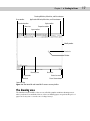
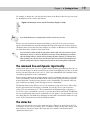
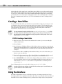
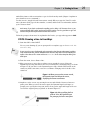
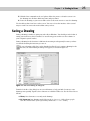
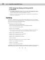
1
C H A P T E R
Starting to Draw
✦
I
RI
AL
n this chapter, I explain the essentials that you need to start drawings. After a little background, I discuss the basics of the screen
that you see when you open AutoCAD or AutoCAD LT, and how to use
it. If you’ve never used AutoCAD or AutoCAD LT before, do the Quick
Start chapter first, “Quick Start: Drawing a Window.”
MA
TE
AutoCAD and its younger brother, AutoCAD LT, are both created by
Autodesk. Together they are the most widely used technical drawing
programs anywhere. AutoCAD alone has more than 3,000,000 registered users. According to Autodesk, CAD stands for computer-aided
design, but can also stand for computer-aided drafting or drawing.
TE
D
The first version of AutoCAD, running under DOS, came out in 1982.
AutoCAD was the first significant CAD program to run on a desktop
computer. At the time, most other technical drawing programs ran on
high-end workstations or even mainframes. AutoCAD LT was introduced in 1993, as a less expensive alternative to AutoCAD, for people
who don’t need all of AutoCAD’s advanced features.
GH
AutoCAD’s advantages
RI
AutoCAD’s success has been attributed to its famous open architecture — the flexibility that the end user has to customize the program
using source code files in plain text (ASCII) format — and programming languages (such as AutoLISP and Visual Basic for Applications).
CO
PY
As a result, AutoCAD is the most flexible drafting program available,
applicable to all fields. AutoCAD’s support for languages other than
English, including those using other alphabets, is unparalleled, making AutoCAD highly popular abroad. As a result, AutoCAD is used in
all disciplines and in more than 150 countries.
Through a high level of technical innovation and expertise, Autodesk
has created a program with unequaled features and capabilities,
including 3D surface and solid modeling and visualization, access to
external databases, intelligent dimensioning, importing and exporting
of other file formats, Internet support, and much more.
The major disciplines that use AutoCAD are:
✦ Architectural, Engineering, and Construction (AEC)
✦ Mechanical
✦ Geographic Information Systems (GIS)
✦
✦
✦
In This Chapter
Getting acquainted
with AutoCAD and
AutoCAD LT
Starting AutoCAD and
AutoCAD LT
Creating a new
drawing
Using the AutoCAD and
AutoCAD LT interface
Saving your drawing
Closing a drawing and
exiting AutoCAD and
AutoCAD LT
✦
✦
✦
✦
14
Part I ✦ AutoCAD and AutoCAD LT Basics
✦ Surveying and Civil Engineering
✦ Facilities Management
✦ Electrical/electronic
✦ Multimedia
However, AutoCAD has many other lesser-known uses, such as pattern making in the garment
industry, sign making, and so on. In this book, I try to provide examples from many fields. The
world of AutoCAD is very broad, and you can learn from seeing the many approaches that
AutoCAD makes possible.
Comparing AutoCAD and AutoCAD LT
AutoCAD LT’s advantages are its lower cost and its compatibility with AutoCAD. The programming code that is used to create AutoCAD LT is a subset of the code used in AutoCAD.
Here are the major differences between AutoCAD and AutoCAD LT:
✦ AutoCAD includes features that enable CAD managers to hold drawings to certain
standards, such as for layer names and text styles. AutoCAD LT doesn’t contain these
features.
✦ AutoCAD LT is not as customizable as AutoCAD, which is both programmable and fully
customizable.
✦ AutoCAD LT includes minimal options for 3D; AutoCAD includes a full-featured 3D
capability.
✦ AutoCAD LT has fewer presentation features than AutoCAD, which includes gradient
fills, true color display, and 3D rendering.
✦ AutoCAD LT is deployable on a network but does not have AutoCAD’s network license
management feature that includes reporting and flexible licensing.
✦ AutoCAD LT does not offer database connectivity; AutoCAD does.
✦ AutoCAD LT does not include AutoCAD’s quick-dimensioning feature, which allows you
to quickly insert a number of dimensions, one after the other.
✦ AutoCAD LT does not come with Express Tools, a set of additional routines that ship
with AutoCAD.
✦ AutoCAD LT does not include sheet sets and fields, two features that were introduced
in AutoCAD 2005.
AutoCAD and AutoCAD LT have a few other minor differences, as well. Some of these differences are only in the user interface, so that you can accomplish the same task but the procedure is slightly different.
Chapter 1 ✦ Starting to Draw
Starting AutoCAD and AutoCAD LT
This section starts a quick tour of AutoCAD and AutoCAD LT. The first step is to start the
program.
On the
CD-ROM
The CD-ROM contains a 30-day trial version of AutoCAD 2007 in Software\AutoCAD
2007\AutoCAD2007Trial.exe. You cannot install AutoCAD 2007 directly from the
CD-ROM. To install AutoCAD, you need to first copy the AutoCAD2007Trial.exe file to your
hard drive. Double-click the AutoCAD2007Trial.exe file. In the WinZip Self-Extractor dialog
box that opens, click the Unzip button to decompress the file. When this process is completed,
the installation process should automatically start; if not, double-click Setup.exe in the
folder to which you unzipped. You can order a free trial of AutoCAD LT 2007 (in the United
States and Canada) at http://usa.autodesk.com/adsk/servlet/index?siteID=
123112&id=2768181.
This book covers AutoCAD 2007 and AutoCAD LT 2007 running on Windows 2000 or Windows
XP Home/Professional. Every computer is set up somewhat differently, so you may need to
adjust the following steps slightly. If you didn’t install the software yourself and are unfamiliar
with the folders (also called directories) on your computer, get help from someone who is
familiar with your computer system.
CrossReference
If you need information on installing AutoCAD or AutoCAD LT, see Appendix A. Appendix A
also covers configuring the software and printers or plotters.
By default, installing AutoCAD or AutoCAD LT places a shortcut on your desktop, as shown in
Figure 1-1. You can double-click one of the shortcuts to launch the program that is installed
on your machine, or you may choose one of the following:
✦ For AutoCAD: Start ➪ (All) Programs ➪ Autodesk ➪ AutoCAD 2007 ➪ AutoCAD 2007
✦ For AutoCAD LT: Start ➪ (All) Programs ➪ Autodesk ➪ AutoCAD LT 2007 ➪ AutoCAD
LT 2007
Figure 1-1: A shortcut on the desktop provides a quick way to open
AutoCAD or AutoCAD LT.
Creating a New Drawing
After you launch AutoCAD or AutoCAD LT, it automatically opens a new drawing named
Drawing1.dwg. You can see the drawing name on the title bar. You can start drawing immediately. In Chapter 2, I explain how to start a drawing based on a template and how to open an
existing drawing.
STEPS: Starting AutoCAD or AutoCAD LT
1. Click Start on the taskbar at the bottom of your screen.
2. Choose one of the following:
15
16
Part I ✦ AutoCAD and AutoCAD LT Basics
• For AutoCAD: (All) Programs ➪ Autodesk ➪ AutoCAD 2007 ➪ AutoCAD 2007
• For AutoCAD LT: (All) Programs ➪ Autodesk ➪ AutoCAD LT 2007 ➪ AutoCAD LT
2007
In AutoCAD, you see a Workspaces dialog box that allows you to choose from AutoCAD
Classic and 3D Modeling. AutoCAD Classis is suitable for 2D drawing, so if you’re just learning AutoCAD, choose that option and click OK.
You see a blank drawing named Drawing1.dwg.
If you are continuing with this chapter, keep this drawing open. I cover exiting from AutoCAD
and AutoCAD LT later in this chapter.
Using the AutoCAD and AutoCAD LT Interface
As I mentioned in the previous section, AutoCAD offers two quite different screens, depending on whether you want to work in 2D or 3D. The 3D working environment is quite different
from the AutoCAD LT screen, but the AutoCAD 2D and the AutoCAD LT environments are similar. In this section, I discuss AutoCAD’s 2D environment.
New
Feature
AutoCAD now offers a separate 3D working environment, which includes the 3D Modeling
workspace and a new acad3D.dwt template. (I cover templates in Chapter 2.) I cover this
3D environment in Part IV, Drawing in Three Dimensions.
Figure 1-2 shows the screen that appears when you first open AutoCAD using the AutoCAD
Classic workspace or AutoCAD LT. Your screen may look somewhat different — remember
that AutoCAD and AutoCAD LT can be customized in many ways — but the general features
will be the same.
Note
You may see several other items on your screen, such as the Tool Palettes window, the Sheet
Set Manager, the Info Palette, and so on. You can close all these items by clicking their Close
(X) button. I discuss these tools throughout the book, as they relate to the current topic. Also,
by default, the screen is black, rather than the white screen you see in Figure 1-2. You can
leave it that way or change the drawing area color, as I explain in Appendix A.
Note
If you find yourself in a 3D environment in AutoCAD, you’ll see a gray background and a perspective view. To work in 2D in AutoCAD, you need to switch to a 2D environment.
To switch to a 2D environment, follow these steps in AutoCAD:
1. From the Workspaces toolbar, choose AutoCAD Classic from the drop-down list. This
displays toolbars with 2D commands.
2. Choose File ➪ New. From the Select Template dialog box, choose acad.dwt and click
Open. This places you in a 2D view and turns off the grid.
The AutoCAD and AutoCAD LT screens consist of four important areas. These are discussed
in the following sections.
Chapter 1 ✦ Starting to Draw
Drawing Minimize, Maximize, and Close buttons
Draw toolbar
Application Minimize, Maximize, and Close buttons
Standard toolbar
Styles toolbar
Menu bar
Properties toolbar
Layers toolbar
Modify toolbar
Crosshairs
Pickbox
Drawing area
Layout tabs
Model tab
Status bar
Status bar menu
Clean Screen button
Command line
Figure 1-2: The AutoCAD and AutoCAD LT screens are very similar.
The drawing area
The blank area in the middle of the screen, called the graphics window or drawing area, is
where you draw. You can think of this as a sheet of drafting paper, except that this piece of
paper can be any size — even the size of a huge factory!
17
18
Part I ✦ AutoCAD and AutoCAD LT Basics
By default, you draw in model space, so called because that’s where you draw your models.
When you create a new drawing, by default, you are in model space, so that you can just start
drawing. You can lay out your drawings for plotting in paper space, also called a layout. To
switch from model space to a layout, you use the tabs at the bottom of the drawing area. (See
“Creating a Layout in Paper Space” in Chapter 17 for details.)
When you start to draw, you need to specify where to start drawing. One way is to use coordinates. To specify a coordinate, the universally accepted convention is to put the X coordinate
first, followed by a comma, and then the Y coordinate. Examples are –3,5, 3,2, 6,–2, and –1,–1.
These coordinates specify points in the drawing area.
CrossReference
Chapter 4 is devoted to explaining how to specify coordinates. To create three-dimensional
models, you need to add a Z coordinate when specifying a point. Chapter 21 discusses threedimensional coordinates.
If you want the maximum amount of free space for drawing, click the Clean Screen button at
the right side of the status bar to remove the title bar, toolbars, palettes, and the status bar.
Click the same button to get them back. You can also press Ctrl+0 to toggle between the two
displays.
Tip
The UCS icon
Notice the symbol with two arrows in the drawing area in Figure 1-2. This symbol is called the
User Coordinate System (UCS) icon. The arrows point to the positive directions of the X and
Y axes to help you keep your bearings. (In a 3D environment, you see a Z axis, as well.)
CrossReference
You can change the look of this icon, and turn it on and off, as I explain in Chapter 8.
The crosshairs
In the drawing area of Figure 1-2, notice the intersecting lines with a small box at their intersection. The small box is called the pickbox because it helps you to select, or pick, objects.
The lines are called crosshairs. They show you the location of the mouse cursor in relation to
other objects in your drawing.
As you move your mouse around, the pickbox and crosshairs move with your mouse. At the
bottom of your screen, at the left end of the status bar (described later), you can see the X,Y
coordinates change as you move your mouse.
The menus and toolbars
At the top of your screen is the title bar, and directly beneath the title bar is a menu bar.
Below that are one or two rows of toolbars. In addition, your screen displays two more toolbars, the Draw and Modify toolbars, which are probably docked at the left and right sides of
the screen (refer to Figure 1-2). Use the menus and toolbars together to give AutoCAD or
AutoCAD LT commands to draw, edit, display information, and so on. I explain how to manage
toolbars in Chapter 3, in the “Using toolbars” section.
On the Draw toolbar, move the mouse cursor over the first button. (If you don’t see the Draw
toolbar, right-click any toolbar button and choose Draw from the list of toolbars.) You should
see a tooltip that says Line, as shown in Figure 1-3. Also notice the status bar, which tells you
that this button creates straight-line segments. You use toolbar buttons to execute commands.
Chapter 1 ✦ Starting to Draw
For example, to draw a line, you click the Line button on the Draw toolbar. You get some practice drawing lines in the exercise that follows.
Figure 1-3: Moving the cursor over the Line button displays a tooltip.
Note
If you inadvertently start a command that you don’t want to use, press Esc.
Because you can customize the menus and toolbars to suit your needs, your screen may
appear somewhat different. AutoCAD and AutoCAD LT provide many more toolbars that you
can display when you need them. Some examples of toolbars are Dimension, View, and Zoom.
You learn about these, and more, later in this book.
Tip
You can lock the position of toolbars and palettes. On the right side of the status bar, at the
bottom of the screen, is a lock icon. Click this icon to open a menu allowing you to individually lock floating toolbars, docked toolbars, floating windows (palettes), and docked windows (palettes). You can also choose the All option and lock or unlock all your toolbars and
palettes. Locking these interface components prevents you from moving them inadvertently.
The command line and dynamic input tooltip
At the bottom of the screen, you see a separate window showing approximately three lines of
text. (You can change it to show as many lines as you like by dragging the top edge of the window up or down.) Notice the word Command:. This is the command line. All commands can be
executed by typing them on the command line.
Even if you use a menu item or toolbar button to execute a command, you may see a response
on the command line. AutoCAD and AutoCAD LT often provide options that must be typed in
from the keyboard. Text that you type appears on the command line. For example, when you
type coordinates specifying a point, they appear on the command line.
The Dynamic Input tooltip allows you to see the text that you type at the cursor. This tooltip
doesn’t appear until you start typing a command. You can also choose options near the
tooltip. (For more information, see “The Command Line and Dynamic Input” in Chapter 3.)
To see more of the command line, press F2 to open the AutoCAD or AutoCAD LT Text Window.
You can scroll back through previous commands. Press F2 again to close the window. You can
also simply hide the Text window by clicking in the AutoCAD or AutoCAD LT window for easy
access to the Text window later from the Windows taskbar.
The status bar
At the very bottom of the screen is the status bar (refer to Figure 1-2). At the left are the X,Y
coordinates. As you move your mouse, these coordinates change. (If they don’t change, click
them and move your mouse again.) The status bar also contains several buttons that I
explain later in this book.
19
20
Part I ✦ AutoCAD and AutoCAD LT Basics
At the right side of the status bar is a small down arrow. Click it to open the status bar menu.
This menu determines which buttons appear on the status bar. If you don’t use a certain button, choose it on the menu to remove its checkmark and make it disappear. You can always
go back and choose the item again to redisplay the button. Also at the right side of the status
bar is the Communication Center icon. (See “The Communication Center” in Chapter 26 for
details.)
Creating a New Folder
For your work with this book, you should create a new folder so that you can save your exercise drawings where they won’t get mixed up with other drawings. The following directions
leave it up to you where to create this new folder. Each computer system is organized differently. If you aren’t sure what to do, choose the drive (not the folder) where AutoCAD or
AutoCAD LT is installed and create a new folder there.
Caution
I do not recommend creating a subfolder in the AutoCAD 2007 or AutoCAD LT 2007 folder.
This folder contains the files that make up the program. If you keep your drawings here, it is
too easy to make a mistake and delete necessary program files. Some people create a subfolder in the My Documents folder.
STEPS: Creating a New Folder
1. Move the mouse cursor down to the taskbar at the bottom of your screen and rightclick the Start button.
2. Choose Explore.
3. On the left pane of Windows Explorer, click the drive where you want to create the new
folder. If you don’t know where to create the folder, choose the drive where AutoCAD or
AutoCAD LT is installed. If you’re on a network, choose the drive that represents your
computer.
4. If you want to make a subfolder (a folder within a folder), choose the folder where you
want to create the subfolder.
5. From the Explorer menu, choose File ➪ New ➪ Folder. A new, highlighted folder, named
New Folder, appears in the right pane. You may have to scroll down to see it.
6. Type AutoCAD Bible for the folder name and press Enter. (If you did the exercises from
a previous edition of this book, such as AutoCAD 2006 Bible, and you already have a
folder named AutoCAD Bible, first rename the original folder to something such as
ACAD2006Bible.)
Save all drawings that you create for this book in your AutoCAD Bible folder.
Caution
Creating a folder for your drawings as described in the previous steps is essential before you
go on to exercises in the rest of this book.
Using the Interface
If you did the Quick Start exercise, you had the experience of drawing a window, but I chose
the simplest method of completing each task because I had not yet described the AutoCAD and
AutoCAD LT screen. In the following exercise, you draw some simple objects, but experiment
Chapter 1 ✦ Starting to Draw
with all the features of the user interface to get a feel for how they work. (Chapter 3 explains in
more detail how to use commands.)
For this exercise, simply follow the instructions exactly. When you type the X and Y coordinates (shown in bold), type the first number, a comma, and then the second number, with no
spaces between them.
Tip
Don’t worry if you don’t understand everything you’re doing. It all becomes clear as you
progress through this book. If you haven’t read the Preface, now is a good time to go back
and read the part that explains how to follow the exercises.
Follow the prompts shown next. As explained in the Preface, you type what appears in bold.
STEPS: Drawing a Line in Four Ways
1. Start AutoCAD or AutoCAD LT.
You see a new drawing. (If you are prompted for a template, type or choose acad.dwt.
or acadlt.dwt.)
Note
If your screen has a gray background and a perspective view (the 3D environment), switch to
a 2D environment. First, choose AutoCAD Classic from the drop-down list in the Workspaces
toolbar. Then choose File ➪ New and choose acad.dwt in the Select Template dialog box.
Click Open.
2. From the menu, choose Draw ➪ Line.
3. Move your mouse to move the crosshairs cursor around the screen. Notice the
Dynamic Input tooltip that follows the cursor around (like a well-trained dog), as shown
in Figure 1-4. (If you don’t see the Dynamic Input tooltip, click the DYN button on the
status bar.) At the same time, notice the coordinates changing on the left side of the
status bar.
Figure 1-4: When you move the mouse around,
the Dynamic Input bar follows the cursor,
displaying the current coordinates.
4. Anywhere on the screen, stop moving the mouse and click the left mouse button to
pick a point. When you move the mouse again, the Dynamic Input bar changes to
prompt you to specify the next point, and to show you the angle and length of the cursor from the original point you picked, as shown in Figure 1-5.
Figure 1-5: After specifying the first
point of a line, the Dynamic Input
bar prompts you for the next point.
21
22
Part I ✦ AutoCAD and AutoCAD LT Basics
5. Pick any point to create a line segment. You see the same Dynamic Input tooltip as
before, which means that you can continue to create more line segments. (Chapter 6 is
all about drawing lines.)
6. Press Enter to end the command and finish your line.
7.
For your second line, choose Line from the Draw toolbar. (Figure 1-2 labels this
toolbar.) Again, pick any point on the screen.
8. Move your mouse so you can see the length and angle tooltips. Notice the value for the
length. Now type a different value and press Enter. For example, if the Length tooltip
says 13.7638, type 5 ↵.
9. Press Enter to end the command. The line’s length is based on what you typed, not
where the cursor was, but the line’s angle is the same as it was before you typed in the
length.
10. For your third line, type line. Notice that the text appears in the Dynamic Input tooltip
as you type, but not in the command-line area.
11. Press Enter. You now see the command that you typed in the command line area as well
as the Dynamic Input prompt to specify the first point.
12. Click in two places to pick a start point and an endpoint.
13. This time, to end the line, right-click anywhere in the drawing area. By default, this
opens a shortcut menu, but it may end the command. If so, you’re done. If you see the
shortcut menu, choose Enter from the shortcut menu to end the command.
14. For your fourth line, choose Tools ➪ Palettes ➪ Tool Palettes Window from the menu.
Click the Command tab, as shown in Figure 1-6. (Because of the many tabs, you may see
only part of the tab title. If you can’t find the Command tab, click the overlapping tabs
at the bottom and choose Command Tools from the list of tabs.)
Figure 1-6: You can execute commands from the Tool Palettes
window.
Chapter 1 ✦ Starting to Draw
15. Click the Line command on the tool palette. Move the mouse so that the cursor is in
the drawing area. Pick two different points and press Enter.
16. Leave the drawing on your screen and read on to the next exercise to save the drawing.
You should now have four lines on the screen. You can see how the interface offers several
ways to work. You can use the method that suits you best.
Saving a Drawing
Saving a drawing is similar to saving any other file in Windows. You should get in the habit of
saving your work every 10 to 15 minutes to avoid losing your work in case the software or
your computer system crashes.
Saving a drawing for the first time is different from saving it subsequently because you have
to name the drawing the first time you save it.
To save a drawing, click Save on the Standard toolbar. If you’re saving a drawing for the
first time, the Save Drawing As dialog box appears, as shown in Figure 1-7.
Figure 1-7: The Save Drawing As dialog box.
Down the left side of the dialog box are several buttons to help you find a location to save
drawings more quickly. Together, these buttons are called the Places list. Use the Places list as
follows:
✦ History lists shortcuts to recently used drawings.
✦ My Documents lists drawings and folders in the My Documents folder. Some people
store files in this folder. (Your system may call this the Personal folder.)
23
24
Part I ✦ AutoCAD and AutoCAD LT Basics
✦ Favorites lists files and folders in the C:\Documents and Settings\[login name]\
Favorites folder. (This is the location in Windows XP; it may be different on your computer.) You may have an Autodesk subfolder; if so, double-click the Autodesk subfolder
to save a drawing there. Usually, this folder contains only shortcuts to files saved elsewhere. To put a shortcut to an already saved drawing in Favorites, choose File ➪ Save As
and click the Tools drop-down list; then click Add to Favorites. You can later open the
file from the Favorites folder.
✦ Desktop shows drawings on your desktop. Some of the Windows icons also appear on
this list.
✦ FTP switches you to the FTP locations folder, where you can find an FTP location that
you have set up, as explained in the following discussion of the Tools drop-down list.
✦ Buzzsaw sends you to www.buzzsaw.com, the Autodesk business-to-business portal for
the building design and construction industry. You can set up a new account or access
existing projects.
Tip
Conveniently, you can reorder the buttons in the Places list. Just drag any button to a new
location.
Of course, you can also choose a location from the Save In drop-down list to which you want
to save the file. To save a file, type a filename in the File Name text box and click Save to save
the file.
Use the Views drop-down list of the dialog box to specify how you want to display files in this
dialog box. List just displays the name; Details adds the file size, type, and date modified;
Thumbnails and Preview add a preview image of the drawing.
Use the Tools drop-down list of the dialog box to do the following:
✦ Add or Modify FTP Locations: FTP sites are locations on the Internet for transferring
files. To add or modify FTP locations, choose Tools ➪ Add/Modify FTP Locations from
the menu of the Save Drawing As dialog box. You need to list the name of the FTP site,
choose a logon type (Anonymous or User), and specify your user name and password if
you’re logging on as a User. You can then save drawings (called uploading) to FTP locations by clicking the Save In drop-down list and choosing FTP Locations. This feature
makes an intranet or any server with FTP capability as accessible as your own computer system.
✦ Add Current Folder to Places: If you save to a specific folder often, you can navigate to
that folder and then choose Tools ➪ Add Current Folder to Places. The Places Bar then
displays a new button for that folder so that you can easily click the button to go
straight to the folder.
✦ Add to Favorites: When you have navigated to a folder, you can add it to the
Favorites folder by choosing Tools ➪ Add to Favorites. You can also select a file in a
folder and add it to the Favorites folder.
✦ Options: The Options dialog box opens, where you can specify certain settings relating
to saving drawings.
✦ Security Options: Choose this setting to set a password or attach a digital signature. I
discuss these features in Chapter 26.
Chapter 1 ✦ Starting to Draw
The SAVEALL command of the Express Tools saves all open drawings, without closing them.
Choose Express ➪ File tools ➪ Save All Drawings. If a drawing hasn’t been saved, you are
prompted for a filename. For information on installing Express Tools, see Appendix A.
The CD-ROM includes a small program, savea.lsp, that automatically backs up your drawing to the floppy drive after you’ve saved it on your hard drive. If you like to back up to a
diskette regularly for safety, this program can be useful. Look in \Software\Chapter
01\Savea. (AutoCAD only.)
On the
CD-ROM
STEPS: Saving a Drawing for the First Time
1.
The four lines you created earlier in this chapter should still be on your screen.
Click Save on the Standard toolbar. The Save Drawing As dialog box opens.
2. Click the Save In drop-down list. If necessary, choose the drive where you created your
AutoCAD Bible folder for this book.
3. Double-click the AutoCAD Bible folder.
4. In the File Name text box, select the filename. Type ab01-01 and press Enter (or click
Save).
5. Keep your drawing on the screen and go to the next exercise.
AutoCAD saves your drawing under the name ab01-01.dwg. This numbering system will help
you organize your drawings from this book and find equivalent drawings on the CD-ROM
more easily. It just means that this is the first drawing from Chapter 1 of AutoCAD 2007 and
AutoCAD LT 2007 Bible.
Closing a Drawing and Exiting from AutoCAD and
AutoCAD LT
You can close your drawing and keep AutoCAD or AutoCAD LT open. The simplest way to do
this is to use the drawing Close button just under the application Close button. You can also
choose File ➪ Close.
Tip
You can choose Window ➪ Close All to close all open drawings. If any of the open drawings
have unsaved changes, AutoCAD or AutoCAD LT prompts you to save the changes. If you
have AutoCAD and you installed the Express Tools (see Appendix A for details), you can
choose Express ➪ File tools ➪ Quick Exit, which closes all open drawings (prompting you to
save if necessary), and then exits the program.
To exit AutoCAD or AutoCAD LT, click the Close (X) box at the top-right corner of your screen.
You can also exit out of AutoCAD or AutoCAD LT by typing quit on the command line and
pressing Enter. Another method is to choose File ➪ Exit.
If you’ve made any changes to your drawing since last saving it, AutoCAD or AutoCAD LT asks
you if you want to save your changes. Choose Yes or No as your situation requires. Choosing
Cancel returns you to your drawing. If you have opened more than one drawing to which you
have made changes, you have a chance to save each drawing in turn so that you don’t exit
AutoCAD or AutoCAD LT without saving all the changes you’ve made in your open drawings.
25
26
Part I ✦ AutoCAD and AutoCAD LT Basics
STEPS: Closing Your Drawing and Exiting AutoCAD
or AutoCAD LT
1. Your drawing should still be on your screen. Choose File ➪ Close. You now see a gray
screen with no drawing. (Repeat this process if you have other drawings open. Save or
cancel the changes to these extra open drawings as you like.)
2. Click the Close button in the upper-right corner to exit AutoCAD or AutoCAD LT. The
program closes immediately.
Summary
In Chapter 1, I explained how to start AutoCAD and AutoCAD LT and create a new drawing. I
gave you a tour of the screen and explained how to save a drawing. This chapter provides the
basis for all your work in AutoCAD and AutoCAD LT.
In this chapter, you learned the following:
✦ A brief history of AutoCAD and AutoCAD LT
✦ Some of the different disciplines that use AutoCAD and AutoCAD LT
✦ How to start AutoCAD and AutoCAD LT
✦ How to start a new drawing
✦ The user interface and its various sections, including the drawing area, the UCS icon,
the crosshairs, the menus and toolbars, the command line, and the status bar
✦ How to start a command from a toolbar
✦ How to start a command from the command line
✦ How to start a command from the menu
✦ How to start a command from a tool palette
✦ How to draw lines
✦ Two ways to pick points on the screen to specify coordinates
✦ How to save a drawing for the first time
✦ How to close a drawing
✦ How to exit AutoCAD and AutoCAD LT
You may have several questions at this point, but “well begun is half done.” The next chapter
explains all the ways to start a new drawing as well as how to open an existing drawing.
✦
✦
✦