1
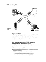
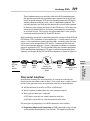
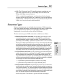
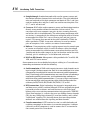
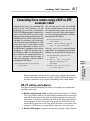
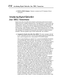
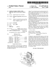
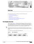
Chapter 1: Wide-Area
Networking Basics
AL
Exam Objectives
✓ Defining wide-area networking
RI
✓ Explaining WAN connection types
✓ Describing WAN protocol encapsulation methods
TE
✓ Introducing Cisco router cabling standards
✓ Identifying AUX and COM port connectors
MA
✓ Understanding popular DSL technologies
D
✓ Recognizing the differences between DCE and DTE devices
TE
Introducing WANs
A
CO
PY
RI
GH
wide-area network (WAN) is a connection between two or more
local-area networks (LANs) spanning across a large, spread-out
geographical area. A single LAN is usually considered to be confined to the
same building or office that does not communicate over public transportation
methods. A metropolitan-area network (MAN) limits its communications to
a specific city function or campus area, while a WAN uses dedicated leased
lines from telephone companies to establish links between geographically
dispersed LANs and/or MANs. WAN technologies are generally represented
by the three lower layers of the OSI model, namely, the network, data link,
and physical layers.
The Internet is the best example of a WAN and is the largest public
network on the planet. As you can see in Figure 1-1, private WANs are used
to establish permanent communications links between company sites and
branch offices. Using routers, traffic is managed and sent to the proper
destination LAN. The traffic is then transferred to LAN switching devices
until the data reaches the intended recipient. Private WANs may use a
number of methods to connect to remote sites, such as dedicated telephone
lines, ATM, Frame Relay, and satellite links. Private WANs may also use
public networks to communicate. Setting up an encrypted VPN over a local
ISP’s DSL service or dialup connection is another cost-friendly alternative
for secure communications.
Introducing WANs
Remote/Home
Office
T3
Le De
as dic
ed a
Lin ted
e
808
AD
SL
Corporate
Headquarters
Managed
WAN
y
ela
F
Figure 1-1:
WAN.
eR
ram
R
Sa emo
te te
VP littl
N e
Branch
Office
Mobile User
Purpose of WANs
A wide variety of options exist to interconnect remote LAN sites. LANs are
brought together into WANs for the purpose of sharing network resources
between authorized users and devices. Collaborative data and resource
sharing between corporate sites and business partners allows WANs to
globally interconnect any business.
Data terminal equipment (DTE) and data
communications equipment (DCE)
Basic WAN connectivity between the subscriber and provider relies on two
types of serial communications devices:
✦ Data terminal equipment (DTE)
✦ Data communications equipment (DCE), also known as data circuit
terminating equipment
A DCE device is typically a modem known as either
• Terminal adapter/network termination 1 (TA/NT1)
• Channel service unit/data service unit (CSU/DSU)
Introducing WANs
809
These hardware devices are used to establish the WAN communications
link and are responsible for translating frames between the local LAN and
the ISP or phone company. DCE units are located between the DTE device
and the transmission link or circuit, such as a dedicated leased line. The
transmission link is the WAN path the data travels to reach other networks.
DCE devices also control the clock rate for DTE devices. DCEs allow the
timing for all network devices to remain synchronized by maintaining
an accurate bit rate. This ensures that all network data is time synchronized and readable between DCE and DTE devices.
WAN connectivity would not be possible without the services of both DCE and
DTE devices. DTEs are known as user-side devices — usually routers or computers — that interconnect packet-switching LANs, converting user data into
signals that can be interpreted by DCE devices. Customer devices that connect to the telephone company’s (telco’s) equipment are known as customer
premises equipment (CPE). The site location where the customer equipment
(DTE) and telephone equipment (DCE) meet is called the demarcation point
(demarc). An example of the DCE and DTE arrangement is shown in Figure 1-2.
Book VII
Chapter 1
Router
(DTE)
Modem
(DCE)
Transmission
Medium/Telecom
Switch
Modem
(DCE)
Computer Terminal
(DTE)
Cisco serial interfaces
All wide-area networks use serial interfaces as a means of transmission.
Serial transmission allows traffic to flow 1 bit at a time over a single channel
or link. A few questions must be raised when selecting a serial interface:
✦ Will the interface be used by a DTE or a DCE device?
✦ Which signaling standard does the serial interface require?
✦ What type of connector is required?
A DTE device typically has a male connector with pins.
A DCE device typically has a female connector with holes.
The two types of proprietary Cisco WAN connectors are as follows:
✦ Proprietary 60-pin serial connection: A WAN connection using a 60-pin
serial interface developed by Cisco Systems. The opposite end of the
Wide-Area
Networking Basics
Figure 1-2:
DTE and
DCE
devices.
810
Introducing WANs
60-pin serial cable may be EIA/TIA-530, EIA/TIA-449, EIA/TIA-232, V.35, or
X.21 standard connectors, which I examine in the following section.
✦ High-Speed Serial Interface (HSSI): A proprietary smart-serial DTE/DCE
interface developed by Cisco Systems and T3plus Networking for use in
high-speed WAN link communications.
HSSI operates at the physical layer of the OSI model and uses a male,
subminiature 50-pin connector with a maximum cable length of 50 feet.
HSSI provides data transmission rates approaching 52 Mbps by employing differential emitter-coupled logic (ECL). ECL technology enables low
noise and high-speed data communications. HSSI uses a series of four
loopback tests and two control signals to validate the communications
process. These communication checks provide handshaking, internal
self testing, and high reliability features.
DCE serial interfaces
Several types of serial interface standards for WAN communications have
been defined by the Electronic Industries Alliance/Telecommunications
Industry Association (EIA/TIA). The following connectors may be used to
connect to a router’s serial port:
✦ EIA/TIA-530: The standard for synchronous balanced and unbalanced
serial interfaces using inexpensive DB-25 connectors.
EIA/TIA-530 defines a cabling interface standard between a DTE and DCE
device. Differential signaling is used to send high-speed data over long
cable using a combination of send, receive, clocking, control, and handshaking signals to send high-speed data over long cabling. Even though
the EIA/TIA-530 standard reduces the amount of signal pins used from
a 37-pin connector to a 25-pin connector, the most critical electrical signals are carried over and maintained on the 25-pin connector.
✦ EIA/TIA-449: A synchronous serial interface standard used for data networking communications that uses a smaller and less expensive connector than V.35 types.
EIA/TIA-449 signals may travel greater distances than the EIA/TIA-232
standard and support data transfer rates up to 2Mbit/s. The Cisco CAB449MT cable uses a male DB-60-pin connector (Cisco end) to a male
DB-37-pin connector (network end).
✦ EIA/TIA-232: An asynchronous serial interface that uses 9-pin (DB-9) and
25-pin (DB-25) connectors popular on all types of DCE/DTE equipment, personal computers, modems, terminals, and older printers. The EIA/TIA-232
standard is used to transfer binary data between a DCE and DTE device.
Generally, computer serial ports use DTE male pins and DCE devices (such
as modems and other networking equipment) employ female connectors.
Male-to-female and female-to-male gender changers are available. EIA/TIA232 cable lengths are restricted to 50 feet (15 meters).
Connection Types
811
✦ V.35: The OSI physical layer ITU partially balanced standard that supports high-speed data rates up to 2.048 Mbps (but used mostly for
56kbps and 64kbps communications).
V.35 is a standard for synchronous serial interfaces that has become
obsolete in favor of EIA/TIA-449, but it continues to be used and remains
popular today. V.35 eliminates line noise by separately twisting the individual wires carrying data and clock information.
Connection Types
Various connection types are available when designing a WAN connection.
Each type provides advantages and disadvantages that must be understood
prior to implementation. Defining an organization’s WAN traffic flow
requirements is crucial to the success of the WAN design.
The four common types of WAN connections available are as follows:
✦ Dedicated leased line connection: An individual, point-to-point serial
connection that uses a permanently established link to provide guaranteed bandwidth between remote networks. These dedicated circuits
provide up to 44.736-Mbps speeds over a public carrier’s T-1 or T-3 lines.
✦ Circuit-switched connection: The most popular type of WAN connection in
which a physical circuit is established “as needed” between two endpoints
for the duration of the connection. This type of connection requires call
setup of the link to occur before any communications may begin. The physical lines remain unavailable for other users until the connection is dropped.
The two types of serial circuit-switched connections are
• Asynchronous plain old telephone system (POTS) dialup
• Synchronous Integrated Services Digital Network (ISDN)
✦ Packet-switched connection: A point-to-point virtual circuit connection
established using a public carrier’s network, allowing multiple customers to
share carrier resources. The sharing of packet-switched connections between
customers remains transparent to the end user. Packet-switched connections
provide high bandwidth and reduced cost compared to dedicated leased
lines, but are more expensive than ISDN and dialup connections.
Frame Relay and X.25 are known as packet-switched technologies.
Book VII
Chapter 1
Wide-Area
Networking Basics
These types of high-speed connections are “always on” and have the advantage
of minimum overhead compared to other connection types. Also, this persistent connection does not require continuous setup and tear down between
communication phases. The disadvantage of dedicated leased lines is cost (factored by distance between links and the amount of bandwidth assigned to the
single link), because they are more expensive that other connection types.
812
Encapsulation Types
✦ Cell-switched connection: A type of point-to-point packet-switched
connection that uses digital circuits to transmit 53-byte packets called cells.
Asynchronous Transfer Mode (ATM) is an example of a cell-switched WAN.
Encapsulation Types
Encapsulation is the wrapping of data in a particular protocol header to successfully transport the data. Because IP is a network layer protocol, it must
be encapsulated when traversing a WAN (data link/physical layer) link. Cisco
devices support many WAN encapsulation types. Each encapsulation type must
be manually assigned to a router’s serial interface, while identically matching
the corresponding point-to-point link on the other end of the connection.
The configured encapsulation type must be identical between both endpoints on a single link; otherwise, communications will not be possible.
The following sections describe the most popular encapsulation types used
on Cisco devices.
HDLC (High-Level Data Link Control)
Cisco’s default encapsulation type for serial interfaces, HDLC is used to
encapsulate packets into frames over established, dedicated, point-to-point
leased lines. HDLC packets are small and use low overhead, thus making
them quite efficient. HDLC also verifies link integrity and communications by
implementing keepalives and sequence numbering. A downside of HDLC is
that it provides no means for authentication.
The original HDLC specification outlined by the International Organization for
Standardization (ISO) did not provide simultaneous support for multiple network layer protocols. Independent vendors took it upon themselves to make
improvements to the HDLC protocol, which introduced new functionality and
incorporated the use of multiple Layer 3 protocols. Cisco’s proprietary version of HDLC (known as cHDLC) is a synchronous, bit-oriented protocol which
adds a new frame field in the packet header to allow for multi-protocol support. cHDLC uses a link keepalive method called Serial Line Address resolution Protocol (SLARP ) to verify connection availability and integrity.
HDLC encapsulation is the default assignment for serial interfaces. If a nonHDLC encapsulation type is required for link establishment, it must be manually configured by the network administrator on both sides of the link.
PPP (Point-to-Point Protocol)
PPP encapsulates network layer packets and transmits frames over Layer 2
connections used by point-to-point dedicated circuits and asynchronous
Encapsulation Types
813
dialup and ISDN links. PPP features include connection authentication,
encryption, and compression.
Two basic PPP sublayers are as follows:
✦ Network Control Protocol (NCP): Encapsulates heterogeneous network
layer protocols over PPP. This allows multiple, dissimilar protocols to
be transmitted by NCP over the PPP link.
✦ Link Control Protocol (LCP): Manages initial link setup, handshake
negotiations, and ongoing connections during PPP communications. LCP
also manages the termination of point-to-point links.
SLIP (Serial Line Internet Protocol)
SLIP is a very simplistic, nonstandard protocol used to frame and transmit IP
datagrams over serial connections.
Due to its inflexible design, SLIP does not provide additional features such as
encryption, authentication, or error detection and has been widely replaced
by PPP.
Frame Relay
Frame Relay is an OSI Layer 2 protocol that relies on the upper-layer protocols
to handle flow control and error correction responsibilities. Frame Relay uses
virtual circuits to multiplex multiple connections over a single transmission
link between DTE and DCE devices. Service providers assign connection i
dentifiers to customer DTE devices and map them to outgoing ports.
ATM (Asynchronous Transfer Mode)
ATM is packet-switching digital transmission technology that sends voice,
video, and data signals using 53-byte, fixed-length cell relay between end
points over a virtual circuit. An ATM cell contains a 5-byte header and a
48-byte payload (user data), which is processed individually (asynchronously). ATM cells are queued before being multiplexed over the
connection-oriented transmission path.
Packaging data into smaller fixed-size cell units allows jitter reduction and
prevents data-queuing delays known as contention. By preventing contention
in applications where timely delivery of data is crucial — such as voice and
video applications — jitter is reduced and overall performance is improved.
Book VII
Chapter 1
Wide-Area
Networking Basics
Frame Relay is a high-performance packet-switching WAN protocol originally
designed for use with ISDN, which has superseded X.25. Frame Relay uses HDLC
encapsulation between connected devices at T-1 (1.544-Mbps) and T-3 (45-Mbps)
speeds, but is relatively inexpensive compared to ATM or dedicated leased lines.
814
Encapsulation Types
ATM is a popular Layer 2 WAN protocol that establishes data-link layer communications over physical Layer 1 circuits. The link between endpoints must
be established before data transmission may begin. Data bit rates of 155
Mbps over CAT5 cable and 622 Mbps using fiber-optic cable are possible,
with ATM network speeds approaching 10 Gbps. ATM is more expensive
compared to Frame Relay technology.
An ATM network is comprised of multiple ATM switches interconnected by
point-to-point links, which transmits data cells to destination ATM network
interface adapters (known as the ATM endpoints). Examples of ATM endpoints include CSUs, routers, switches, computers, and video coder-decoders (codecs). Two types of ATM switch interfaces are known as either UNI
or NNI. UNI interfaces interconnect ATM end systems to ATM switches. NNI
interfaces connect ATM switches. UNI and NNI interfaces are also classified
by the owner of the interface. The telephone company is assigned publicly
owned interfaces, with private equipment being assigned to the end user
and is known as customer premises equipment (CPE).
The ATM cell headers are defined in either UNI or NNI format, depending on
the type of interface used. Some of the ATM cell header fields are as follows:
✦ Generic Flow Control (GFC): Field used to identify two or more devices
on an ATM network that are using the same ATM interface (multiplexing).
✦ Virtual Path Identifier (VPI) and Virtual Channel Identifier (VCI):
Fields used in determining the ATM cell destination while in transit
through an ATM switched network. Cells are tagged with VPI and VCI
values. A local translation table determines the port address of a
particular destination based on the VPI and VCI values.
✦ Payload Type (PT): Field used to show the type of data carried. Data
may be either user data or control data. If the cell is transporting user
data, the first bit is always set to 0. The bit value changes to 1 when
control data is used. The second bit in the payload type is assigned for
congestion. A 0-bit value represents no congestion, and a 1 bit is used
to register network congestion. If the third bit is on (a 1 bit), the cell is
marked as the last cell in a frame.
✦ Cell Loss Priority (CLP): Field responsible for management of buffering.
If the CLP bit equals 1, the cell will be dropped when congestion on the
network is discovered.
✦ Header Error Control (HEC): Field used in checksum calculations to
determine whether problems exist in the header.
WAN circuits are categorized into two kinds of connection types:
✦ Permanent virtual circuits (PVCs): PVCs establish direct connections
between sites and function similarly to a dedicated leased line. The
Introducing Cable Connections
815
persistent nature of PVC connections allows for a permanent mode of
communications where call setup and termination is not required.
A PVC connection guarantees an “always on” communications availability using a manual static setup method.
✦ Switched virtual circuits (SVCs): SVCs dynamically generate connections
and terminate them after data has been completely transferred, functioning similarly to a telephone call. A signaling protocol is used between the
ATM endpoint and the ATM switch to dynamically control the connection.
SVCs provide flexibility and call setup to networking devices, but require
additional time and overhead to set up the connection.
Both PPP and ATM WAN encapsulation types support asynchronous
communications.
X.25
This is an international WAN protocol family standardized by the ITU’s
Telecommunication Standardization Sector (ITU-T) that defines how
connections are established and maintained between end user devices and
networking equipment.
X.25 network devices are categorized into three types:
✦ Data circuit-terminating equipment (DCE): DCE devices are modems
and packet switches that reside between DTE devices and PSEs.
✦ Packet-switching exchange (PSE): PSEs transfer data between DTE devices
over the X.25 network. X.25 was designed before the conception of the OSI
layer and has been generally replaced by the more efficient Frame Relay
technology, although X.25 is still used in some ISDN scenarios.
Introducing Cable Connections
Cisco routers use either RJ-45 or DB-25 connectors for DCE/DTE console and
AUX ports. A terminal DTE device or DCE modem may be connected to these
ports using an RJ-45 cable and an RJ-45–to–DB-25 or RJ-45–to–DB-9 connector.
RJ-45 cabling
Unshielded twisted-pair (UTP) cable uses four pairs of eight individual wires
twisted together to eliminate electrical interference known as crosstalk. UTP
cables feature RJ-45 connectors that contain eight connector pins per connector. RJ-45 cables are categorized into these main types:
Wide-Area
Networking Basics
✦ Data terminal equipment (DTE): DTE devices are customer-owned computers, terminals, and routers that communicate across the X.25 network.
Book VII
Chapter 1
816
Introducing Cable Connections
✦ Straight-through: Standard network cable used to connect source and
destination interfaces between hubs and switches. The eight individual
wires on both ends of the 8-pin connector are identical. Pins 1 and 2 are
used for sending data, and pins 3 and 6 are used for receiving data. Pins
4, 5, 7, and 8 are not used.
✦ Crossover: RJ-45 cable used to connect a source and destination interface
directly to one another without the need for a hub or switch. The
crossover cable cross-connects two pairs of wires, meaning that each
end of the cable is wired differently. The white/orange and orange solid
set of wires is swapped with the white/green and green solid set of wires
on one end of the cable. Pin 1 crosses over to pin 3 and pin 2 crosses
to pin 6. This means that one end of the cable is defined as T568A, the
other specified as T568B. A crossover cable may be used to connect
pairs of computers, hubs, switches, or routers to one another.
✦ Rollover: Cisco-proprietary cables used to connect into the console port
of a router or a network switch. In an RJ-45 rollover cable, the colored
wiring on one end of the cable becomes reversed on the other end. Pin
1 on one end of the cable connects to pin 8 at the other end of the cable.
Similarly, pin 2 is wired to pin 7 at the other end, and so on.
✦ RJ-45–to–DB-9 female: Management cable provided with Cisco 600, 800,
1600, and 1700 series routers.
Some common uses for unshielded twisted-pair cabling in a Cisco wide-area
networking environment include the following:
✦ Serial transmission: A WAN serial transmission over a single channel consisting of a single 1-bit data transmission. Each bit is transmitted one bit at a time
(compared to the multiple 8-bit transmission nature of parallel communications). Even though serial communications may seem to have a disadvantage
compared to parallel transmissions, serial communications methods are
often faster than parallel communications. Cisco uses a 60-pin serial connector for one end of the serial transmission cable, while the other end of the
cable may be EIA/TIA-232, EIA/TIA-449, EIA/TIA-530, V.35, or X.21.
✦ ISDN connections: Digital technology that transmits integrated voice
and data over a publicly switched network. ISDN was originally designed
to provide private customers and small businesses with high-speed
Internet access over existing communications infrastructures. ISDN BRI
(Basic Rate Interface) is a service that uses two 64-Kbps bearer channels
(2B) plus one 16-Kbps data channel (D) used for clocking, and is called
“out-of-band” signaling. This basically means that two encapsulation
methods are used between the signaling and data channels.
✦ Console connections: A DTE terminal session is established and used
to deliver commands to the router via a console connection. A rollover
cable with an RJ-45 connector is used to connect the PC or terminal to
the console port of the Cisco device.
Introducing Cable Connections
817
Connecting Cisco routers using a DCE-to-DTE
crossover cable
Although Cisco routers are considered DTE
devices (Cisco serial interfaces are DTE
by default), you can create a simulated lab
DCE-to-DTE WAN environment using two Cisco
routers and a DCE-to-DTE crossover cable.
Because channel service unit/data service unit
(CSU/DSU) devices (DCEs) control the timing
(clocking) for synchronous serial interfaces,
one Cisco router must be configured as a DCE
device. Each router’s serial interface should
be configured depending on which end of
the DB-60 cable is plugged in: One interface
configured as a DCE and the other end as
the DTE device. Make sure that both routers’
serial interfaces are configured with the no
shutdown command and the proper IP
addressing information, and then configure
clocking on the DCE device:
RouterDTE(config-if)#clock
rate 64000
%Error: This command applies
only to DCE interfaces
The show controllers command display
output allows an administrator to view which
interfaces are set up for DCE or DTE operation:
RouterDTE#show controllers
serial 0
HD unit 1, idb = 0x711CD0,
driver structure at
0x124140
buffer size 1524 HD unit 1,
V.35 DTE cable
Before connecting a terminal to the console port, configure the terminal
to match the router console port settings, typically 9600 baud, 8 data bits,
no parity, and either 1 or 2 stop bits (depending on the router model).
DB-25 cabling and adapters
The types of cabling and adapters used for Cisco routers are categorized
into these main types:
✦ RS-232 straight-through cable: Standard serial cable known as CAB-R23.
This Cisco router cable uses a female DB-25 connector on one end and a
male DB-25 connector on the other end. Either end may be used by the
network or Cisco device, depending on DCE or DTE device designation
and assignment. If the Cisco router is designated as a DCE device, the
female DB-25 connector is the Cisco end of the cable. If the router is designated as a DTE device, the male DB-25 connector is the Cisco end.
✦ RJ-45–to–DB-9 adapter: Connects a router to a PC through a 9-pin COM port.
Book VII
Chapter 1
Wide-Area
Networking Basics
RouterDCE(config-if)#clock
rate 64000
This command sets the clock rate to 64,000
bits per second. Because no error message
was generated by the router, the command
executed successfully. What would happen if
the same clocking command was mistakenly
executed on the DTE device?
818
Introducing Digital Subscriber Line (DSL) Connections
✦ RJ-45–to–DB-25 adapter: Connects a router to a PC through a 25-pin
serial port.
Introducing Digital Subscriber
Line (DSL) Connections
Digital subscriber line (DSL) data transfer is the high-speed transmission of
digital data over standard telephone lines. The digital data is transmitted over
analog carrier signals using copper wiring. DSL technology enables home and
small business customers to use the same phone line for both high-speed
Internet access and telephone services. This combination of new DSL technology with older analog signaling (POTS) allows high-speed Internet access without requiring the installation of newer and more expensive communications
methods. The most popular types of DSL connections are as follows:
✦ Asymmetric digital subscriber line (ADSL): The most common method
of DSL communication that transfers both analog and digital information
over a pair of copper wires, using either POTS or ISDN signals.
Since a typical home user requires less upstream bandwidth than downstream bandwidth, ADSL allocates the majority of the telephone line
frequencies to downstream traffic. This provides a much larger capacity
for Internet downloading, while restricting a users’ upload bandwidth
considerably. This means data downloads to the end user will occur
much faster than data being uploaded from the user to the Internet.
ADSL line speeds may approach 24 Mbps downstream and 3.5 Mbps
upstream, with data transmission rates fluctuating based on the Internet
service provider (ISP) and line quality of the link. Distance also plays a
factor in data rates. By using a splitter, an ADSL subscriber may simultaneously access both the public switched telephone network (PSTN)
and the Internet on the same twisted-pair copper cabling. The splitter
provides a means to filter between high and low frequencies.
Two DSL modems or ADSL transceiver units (ATUs) are used to establish
a link. One unit, located at the service provider’s central office, is called
the ATU-C; the remote transceiver unit located at the home or business
customer is called the ATU-R. The location where the telephone company’s
copper wires terminate is called the main distribution frame (MDF). The
MDF connects incoming public or private lines to the internal telephone
company’s network inside a wire rack. The digital subscriber line access
multiplexer (DSLAM) is connected to the line at the telephone service
provider via the MDF, and is used to connect multiple customer DSL connections to the Internet backbone using multiplexing. The DSLAM acts as a
Layer 2 switch that collects multiple customer DSL streams and multiplexes
the data into a single signal. This multiplexed traffic is then sent over the
Internet backbone switch called the Network Service Provider (NSP) at
speeds up to 10 Gbps. Figure 1-3 shows an example of a typical ADSL setup.
Introducing Digital Subscriber Line (DSL) Connections
819
✦ PPPoE (Point-to-Point Protocol over Ethernet): An OSI Layer 2 protocol
used to encapsulate PPP frames inside Ethernet frames. PPPoE is typically
used by Internet service providers (ISPs) to allow customers to log on to
DSL services using broadband modems. Based on the older Point-to-Point
Protocol (PPP), ISPs use PPPoE to track an IP address to a specific
customer’s authenticated username and password. This allows users
to establish a virtual point-to-point WAN “dialup” session over Ethernet
networks and securely transmit data between endpoints. PPPoE uses
tunneling for security purposes and is similar to the Point-to-Point
Tunneling Protocol (PPTP) found in virtual private networks. For this
reason, PPPoE consumes additional bandwidth and resources.
✦ Cisco Long Range Ethernet (LRE): A proprietary broadband Ethernet
protocol developed by Cisco Systems that connects LANs or individual
computers to LRE-enabled switches over POTS. LRE is based on VDSL
technology and supports distances up to 1.5 kilometers over standard
phone lines, enabling simultaneous voice, video, and data transfers.
Cisco LRE products are designed to share lines with analog, Integrated
Services Digital Network (ISDN), and digital private branch exchange
(PBX) switch telephones using the 0- to 700-kHz frequency range,
delivering data rates of 5–15 Mbps. This allows Cisco LRE to offer
Ethernet-like performance using lower quality and older Category 1/2/3
cabling. LRE is considered a metropolitan-area network protocol and is
easy to install and manage. Cisco LRE also provides huge speed advantage over standard Internet dialup connections.
Wide-Area
Networking Basics
Router
60-pin serial port
connector
CSU/DSU
or other DCE
Serial transition
cable
Figure 1-3:
ADSL setup.
EIA/TIA-232, EIA/TIA-449, V.35,
X.21, or EIA-530 connector
Book VII
Chapter 1
Wide-Area Networking Basics
Prep Test
1
Which types of devices control the clock rate and timing synchronization for
WAN interfaces? (Choose two.)
A
B
C
D
0
2
50-pin HSSI cable
60-pin DCE-to-DTE crossover cable
CAB-449MT cable
RJ-45 straight-through cable
RJ-45–to–DB-9 female cable
❍
❍
❍
❍
❍
PBX
Demarc
Cisco LRE
Customer premises equipment (CPE)
MAN
Which protocol would be used by an ISP to establish an authenticated
customer dialup session?
A
B
C
D
E
5
❍
❍
❍
❍
❍
What is the name for WAN equipment not located at (but connected to) the
telephone company?
A
B
C
D
E
4
DTE
ATM
MTF
DCE
CSU/DSU
Which type of cable is required to configure a simulated WAN environment
between two routers?
A
B
C
D
E
3
❍
❍
❍
❍
❍
❍
❍
❍
❍
❍
ATM
HDLC
PPPoE
Frame Relay
SLIP
Which technology uses separate channels for data and signaling?
A
B
C
D
❍
❍
❍
❍
ISDN
ADSL
ATM
HDLC
Which simplistic, nonstandard protocol is used to frame and transmit IP
datagrams over serial connections?
A
B
C
D
7
❍
❍
❍
❍
❍
Dedicated leased line
POTS
Frame Relay
ATM
ISDN
❍
❍
❍
❍
ATM
Frame Relay
ISDN
X.25
Which WAN type provides guaranteed bandwidth over an “always on”
connection?
A
B
C
D
11
HDMI
HSSI
60-pin DCE-to-DTE
RJ-45–to–DB-9
Which technologies are examples of packet-switched connections? (Choose
two.)
A
B
C
D
10
❍
❍
❍
❍
Which technologies are examples of circuit-switched connections? (Choose
two.)
A
B
C
D
E
9
ATM
HDLC
SLIP
X.25
Which proprietary interface was developed by Cisco Systems and T3plus
Networking for use in high-speed, WAN link communications?
A
B
C
D
8
❍
❍
❍
❍
❍
❍
❍
❍
Packet-switched network connection
Cell-switched network connection
Circuit-switched network connection
Dedicated leased line connection
What is the best example of a cell-switching technology?
A
B
C
D
❍
❍
❍
❍
X.25
CST
ATM
Ethernet
Wide-Area Networking Basics
6
Wide-Area Networking Basics
Answers
1
D, E. DCE and CSU/DSU. Data communications equipment (DCE), also referred
to as a channel service unit/data service unit (CSU/DSU), controls the timing
synchronization for WAN devices. Review “Data terminal equipment (DTE) and
data communications equipment (DCE).”
2
B. A 60-pin DCE-to-DTE crossover cable is used to establish a simulated DCE-toDTE environment using the serial interface between Cisco routers. See “Cisco
serial interfaces” and “Introducing Cable Connections.”
3
D. Customer premises equipment (CPE) connects to equipment provided by
the telephone company at the demarcation point. Refer to “Data terminal
equipment (DTE) and data communications equipment (DCE).”
4
C. PPPoE. Many Internet service providers use PPPoE to authenticate customers
using a username and password over dialup connections. Take a look at
“Encapsulation Types.”
5
A. ISDN. ISDN BRI (Basic Rate Interface) is a service using two 64-Kbps bearer
channels (2B) plus one 16-Kbps data channel (D) used for clocking, and is called
“out-of-band” signaling. Read “Introducing Cable Connections.”
6
C. SLIP. Serial Line Internet Protocol is a very simplistic, nonstandard protocol
used to frame and transmit IP datagrams over serial connections. See
“Encapsulation Types.”
7
B. HSSI. High-Speed Serial Interface (HSSI) is a proprietary smart-serial DTE/
DCE interface that uses a male, subminiature 50-pin connector with a maximum
cable length of 50 feet. Examine “Cisco serial interfaces.”
8
B, E. POTS and ISDN. The two types of serial circuit-switched connections are
asynchronous plain old telephone system (POTS) dialup and synchronous
Integrated Services Digital Network (ISDN). Look over “Connection Types.”
9
B, D. Frame Relay and X.25 are known as packet-switched technologies and
provide higher bandwidth and cost compared to ISDN and dialup alternatives.
Check out “Connection Types.”
10
D. Dedicated leased line. A dedicated leased line establishes a permanent link
using a point-to-point serial connection, which provides guaranteed bandwidth
to remote networks. Review “Connection Types.”
11
C. ATM. Asynchronous Transfer Mode establishes a point-to-point cell-switched
WAN that transmits 53-byte packets called cells. Refer to “Connection Types.”