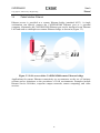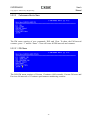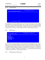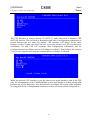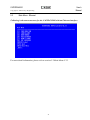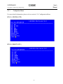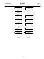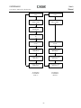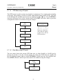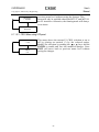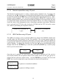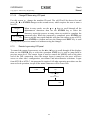
1
CAPSPAN5000 MSDSL ACCESS SYSTEM
Standalone Unit
User’s Manual
Copyright © 2002 Cronyx Engineering
Version 2.1. 31-Oct-2002
CAPSPAN5000
User’s
Manual
Copyright © 2002 Cronyx Engineering
2
CAPSPAN5000
User’s
Manual
Copyright © 2002 Cronyx Engineering
Contents
CAPSPAN5000 MSDSL Access System. Executive Summary................................................................4
Chapter 1. Product Description ............................................................................................................5
Chapter 2. System Overview .............................................................................................................10
Chapter 3. Applications .....................................................................................................................16
Chapter 4. Installation .......................................................................................................................19
Chapter 5. Configuration/Operation....................................................................................................23
Chapter 6. Configuration/Operation using LCD Panel ..........................................................................79
APPENDIX A. Interface Pin Assignments..........................................................................................109
APPENDIX B. Acronym Definitions .................................................................................................. 112
APPENDIX C. Ethernet Remote Bridge Interface Setting ................................................................... 115
3
CAPSPAN5000
User’s
Manual
Copyright © 2002 Cronyx Engineering
CAPSPAN5000 MSDSL Access System
Executive Summary
Today’s bandwidth-hungry application such as Internet access, remote LAN access,
teleconferencing, workgroup and data sharing, telecommuting and numerous varieties of
digital video services are driving today’s demand for high-speed data network access.
Cronyx Corporation designs, develops and markets transmission systems based on
Digital Subscriber Line (DSL) technology for copper wire plant. They support all
contemporary data rates, from 64kbps to multi-megabit symmetric and asymmetric
transmission for voice, video and data communications over a single copper pair. Cronyx
access systems link enterprise LANs and Network Service Providers over private and
public networks across the local loop, the connection between the customer and the first
network node.
Increasing demand for high data rate services makes the copper plant a valuable resource.
Cronyx CAPSPAN5000 systems provide transmission over a single copper pair, more
than doubling the transmission capacity of the existing copper plant.
Cronyx CAPSPAN5000 systems provide full-duplex, T1/E1 and fractional data rates (up
to 2.048 Mbps) over a single pair of wires exceeding 14,000 feet using 24 AWG wire.
CAPSPAN5000 products replace older four-wire T1/E1 and fractional T1/E1 technology
with state of the art technology providing both cost-effective and extended reach (beyond
14,000 feet with mixed gauge wire benefits.)
The CAPSPAN5000 access system provides multiple interface options at both the central
office and the customer premises. Interfaces include V.35, Ethernet Remote Bridge (10
BaseT Port), RS-449/EIA-530 and G.703.
Cronyx provides symmetric MSDSL access systems tailored for environments supporting
a variety of communications. The single-pair CAPSPAN5000 access system provide
high-speed transmission over a single wire pair supporting rate/reach adjusted or
programmable data rates from 64kbps up to 2.048Mbps.
4
CAPSPAN5000
User’s
Manual
Copyright © 2002 Cronyx Engineering
Chapter 1
Product Description
1.1
Introduction
The CAPSPAN5000 MSDSL access system provides high-speed data access over
single-pair copper wires. It can transmit up to 2.048 Mbps E1 signal without a repeater
for more than 7 Km (24 AWG line) at a Bit Error Rate of less than 10-7.
Using MSDSL transmission technology, the CAPSPAN5000 MSDSL network access
system allows fiber quality transmission on a single pair of copper wire. Using lower
gauge larger copper wire may allow you to attain greater distances.
1.2
Product Interaction
CAPSPAN5000 desktop MSDSL modem that is part of the Cronyx MSDSL access
system. Used in conjunction with the CAPSPAN5000 shelf type CO (Central Office) line
card or desktop MSDSL modem, the unit provides repeaterless data transport of up to
2.048 Mbps, over a single pair of unconditioned copper wire. The rate is automatically
adjusted to synchronize at the highest of eight specified rates (see chart 1), corresponding
to the distance between the local and remote units (see chart 1). Alternatively, the data
rate is software selectable at any of the available Nx64 kbps rates where N is from 1 to
32.
Chart 1: MSDSL SPECIFICATION
Line
Payload
Reach
Symbol
Information Constellation Tx Power
Rate
Rate
24 AWG
Rate
Rate
(kbps)
(kbps)
(kft)
(kbauds)
(Bits/baud)
144
128
29000
72
2
272
256
27900
90.6
400
384
26000
528
512
784
Bandwidth
Line
Impedance
(dBm)
(kHz)
(ohm)
8-CAP
7.4
4-86.8
135
3
16-CAP
8.3
4-108.3
135
133
3
16-CAP
9.7
4-157
135
24800
176
3
16-CAP
11.7
4-206.4
135
768
20500
261
3
16-CAP
12.9
4-304.2
135
1040
1024
19300
260
4
32-CAP
12.9
4-303
135
1552
1536
16900
310
5
64- CAP
13.0
4-306.5
135
2064
2048
14700
344
6
128-CAP
13.0
4-399.6
135
* Reach in feet calculated using 24 AWG, no noise
5
CAPSPAN5000
User’s
Manual
Copyright © 2002 Cronyx Engineering
1.2.1
Operation
The CAPSPAN5000 architecture is listed below:
Interface Connector
Interface
Module
Mainboard
DSL
Transceiver
Module
LEDs (Light Emitting Diode)
Figure 1.1 System Architecture
The desktop MSDSL modem receives its power from the AC power source via an AC
adapter provided by Cronyx.
In E1 or Fractional E1 mode, the local equipment (i.e.: router or PBX) supplies data at
full or fractional E1 speed to the G.703 data port of the CAPSPAN5000. The
CAPSPAN5000 produces a digitized data stream, which is transmitted over the single
copper pair to the line port of its associated CAPSPAN5000 line interface card. The
CAPSPAN5000 interface card then directs the data stream to the central office switch or
other central office equipment for transmission to its destination.
Payload rate can be automatically adjusted to downwards until it finds the highest speed
it can sync to the remote unit, thereby maximizing the rate and reach. At the central office
site, manual rate selection can be performed. It has to base on what fixed rate service is
desired. Utilizing the V.35 or 10BaseT data port, the CAPSPAN5000 MSDSL system can
support un-channelized data rates up to 2.048 Mbps.
6
CAPSPAN5000
User’s
Manual
Copyright © 2002 Cronyx Engineering
1.2.2
System Interface
The CAPSPAN5000 system supports four high-speed digital interfaces, V.35, Ethernet
Remote Bridge (10 BaseT Port), RS-449/EIA-530 and G.703. Configurable items vary
depending on the type of interface being used. System alarms, diagnostics, and
transmission line history will also differ depending on the interface type.
1.2.2.1
V.35
The CAPSPAN5000 supports a V.35 interface with the following characteristics:
• Data and Control signals. The V.35 is a synchronous, high-speed digital type interface.
It uses multiple-wires to carry data and control signals. The V.35 interface has eight
control signals.
• Timing Signals. The V.35 has two timing signals produced by the DCE and supplied
to the DTE. The timing signals for these interfaces are identified in Appendix A.
• The I/O connectors. The pin lists for the interface connectors appear in Appendix A.
1.2.2.2
Ethernet Remote Bridge
The CAPSPAN5000 provides an Ethernet Remote Bridge interface. The Ethernet Remote
Bridge (IEEE standard 802.3) provides one port connected to an Ethernet LAN running
at 10 Mbps and the DSL port connected to the WAN at up to 2.048 Mbps. The bridge
allows an individual Ethernet computer or an Ethernet LAN to connect to the network
through the CAPSPAN5000.
1.2.2.3
EIA-530/RS-449
The CAPSPAN5000 supports both RS-449 and EIA-530. These two interfaces have the
same characteristics, which listed below:
• Both RS-449 and EIA-530 are synchronous, high-speed digital type interface. It uses
multiple-wire to carry data and control signals.
• RS-449 and EIA-530 have two timing signals produced by the DCE and supplied to
the DTE. The timing signals for these interfaces are identified in Appendix A.
• The I/O connectors. The pin lists for the interface connectors appear in Appendix A.
• RS-449 interface uses the EIA-530 interface module in combination with a converter
cable, which adapts the DB25 connector to DB37 connector.
1.2.2.4
G.703
The G.703 (E1) interface uses two pair (four-wires) to carry digital data. This interface
transfers data at full E1 rate of 2.048 Mbps or at any available Fractional E1 rate. The E1
clock signal is either synchronized to the network (CO) or recovered by the
7
CAPSPAN5000
User’s
Manual
Copyright © 2002 Cronyx Engineering
CAPSPAN5000 (CPE). If a CAPSPAN5000 MSDSL system has a G.703 (E1) interface,
you can configure it to:
• Enable or Disable CRC.
1.3
Physical Description
The model illustrated in Figure 1.2, the CAPSPAN5000 modem, is a compact,
lightweight device housed in a plastic and metal enclosure. It is 203 mm long, 198 mm
wide, 36 mm high, and weighs approximately 0.9 Kg.
There is also a model that supports a LCD display on the front panel, shown in Figure 13.
It includes a 2x16-character LCD readout display, four membrane switches, and six
light-emitting diodes (LED’s). It is 210 mm long, 200 mm wide, 40 mm high, and weighs
approximately 0.95 Kg.
1.4
System Interaction
You interact with your system using either (1) the LCD front panel and/or (2) a terminal
or PC connected to the CID port; it depends on what system you purchased. Whatever
method you choose, you’ll select a desired function from the system’s multi-level menu
structure. That function enables you to either:
• Define or change an operating parameter of the system or,
• Display the status and alarm of the system.
1.4.1
Front Panel Interaction
For units with the LCD, the front panel of the CAPSPAN5000 includes four membrane
switches through which you interface with the multi-level menu structure to configure
and monitor the status of the unit and network. The keys are designated with 3, 4,
EXIT and ENTER. The EXIT key is used to jump up to the previous level of menu. The
3and 4 keys are used to scroll through the menu items or make changes. The ENTER
key is used to confirm an operation and in some screens, change displayed items. Chapter
6 contains detailed operating instruction using the LCD and front panel keys.
Figure 1.2 CAPSPAN5000 Front Panel View (Model without LCD)
8
CAPSPAN5000
User’s
Manual
Copyright © 2002 Cronyx Engineering
Figure 1.3 CAPSPAN5000 Front Panel View (Model with LCD)
1.4.2
External PC Interaction
The rear panel of the CAPSPAN5000 includes an RS-232 port marked CID for
connection to a terminal at baud rate of 9600, no parity, 1 stop bit and 8 bits. When
performing CRC and QRSS tests from supervisory port, the connection between the
external PC and the MSDSL unit must always be present. The tests will be terminated
when the connection is removed. Chapter 5 contains detailed supervisory port operating
directions.
1.4.3
Remote Control through Modem Connection
The CAPSPAN5000 modem unit’s supervisory port (CID) can be remote controlled
through a modem connection. In order to use such connection, the null modem is needed
to bridge the connection between modem’s serial port and CAPSPAN5000 modem unit’s
supervisory port. The connection for such null modem is suggested below:
Male (9/25 pin)
Wiring
Male (9/25 pin)
TD (2/3)
TD (2/3)
RD (3/2)
RD (3/2)
RTS (7/4)
RTS (7/4)
CTS (8/5)
CTS (8/5)
DSR (6/6)
DSR (6/6)
DCD (1/8)
DCD (1/8)
DTR (4/20)
DTR (4/20)
RI (9/22)
RI (9/22)
GND (5/7)
GND (5/7)
FG (1/1)
FG (1/1)
9
CAPSPAN5000
User’s
Manual
Copyright © 2002 Cronyx Engineering
Chapter 2
System Overview
2.1
General
The following section describes the CAPSPAN5000 access system, DSL transmission,
performance monitoring, and configuration, alarm management, diagnostics and common
applications.
2.2
System Description
The typical CAPSPAN5000 MSDSL access system consists of a CAPSPAN5000 at the
customer site interfacing with a CAPSPAN5000 line card at the central office over a
Symmetric Digital Subscriber Line transmission line. The system transmits data
symmetrically, at the same rate in both directions, over one pair of copper wires.
The CAPSPAN5000 access system allows existing and new telephone companies to
expeditiously and economically providing this high-speed access to their customers. In
order to satisfy increasing demand for high data rate services, CAPSPAN5000 provides
transmission over a single copper pair more than doubling the transmission capacity of
the existing copper plant. The CAPSPAN5000 single-pair MSDSL access system
maximizes network performance and provisioning flexibility by providing automatic
rate/reach adjustment at the various symmetric data rates (see chart 1).
CAPSPAN5000 is configured and managed locally via a 2x16 character LCD display and
membrane switches on the front panel or via a VT-100 type Terminal connected to the
unit through the CID port on the rear of the unit. It can also be configured and managed
remotely via a terminal connected to the far-end CAPAPAN5000.
2.3
MSDSL Transmission
Today’s bandwidth-hungry applications such as Internet access, remote LAN access,
teleconferencing, workgroup and data sharing, telecommuting and numerous varieties of
digital video services are driving today’s demand for high-speed data network access.
These content rich applications have put extraordinary stress on that vital connection
between the customer and the first network node… the local loop. To address this need
for higher bandwidth and to minimize the bottleneck at the local loop, the
telecommunications industry has developed a set of new technologies, the most
significant of which is Digital Subscriber Line (DSL) transmission.
Many types of DSL have been developed for various applications; the most pervasive of
which is High-bit-rate Digital Subscriber Line (HDSL) that uses two-pairs of copper wire.
To provision a 9,000-foot local loop with traditional E1 equipment, you would need two
10
CAPSPAN5000
User’s
Manual
Copyright © 2002 Cronyx Engineering
transceivers and two repeaters. To provision the same loop with HDSL, you only need
two transceivers, one at each end of the line. But you still need two pairs of copper wire.
Copper wire is the most pervasive transmission medium in the world today, especially in
the local loop; and HDSL supports the transmission and receipt of digital data at speeds
up to 1.024 Mbps in both directions simultaneously on a single pair of copper wire.
MSDSL address both the need for higher bandwidth and the efficient use of existing
copper by combining the latest MSDSL technology to transmit and receive traffic at
64kbps and higher speeds up to 29,000 feet while using only one-pair of 24 AWG copper
wire.
Because only one pair of copper wire is needed with MSDSL technology, the capacity of
the local loop infrastructure is enhanced dramatically. The multi-rate capability of the
CAPSPAN5000 MSDSL access system provides needed flexibility for service providers
deploying today’s digital services.
2.4
Real-time Performance Monitoring
The system provides extensive real-time, non-disruptive monitoring of system
performance. DSL transmission and interface port parameters are continuously monitored.
Current and historical data is available to assist you in identify sources of problems
during troubleshooting.
2.4.1
Monitored Parameters
Signal/Noise Ratio: This is a DSL transmission parameter, measured in dB, which
indicates the Signal-to-Noise (S/N) ratio at a receiver point. The signal-to-noise value is
available on the LCD front panel or the CID’s status screen and the value is updated
every second.
DSL CRC-6: This is a 6-bit word in every DSL frame, representing a calculation based
on all the bits in that frame except for FAW and CRC-6 bit word. Any mismatch at the
receiver, between the received CRC-6 and the one calculated based on the received data
in the frame, indicates one or more bits were received in error in that second and it is
considered and Errored Second (ES).
DSL Sync Loss: To assure proper synchronization between DSL transceivers, a sync
word is generated in every frame. A sync loss is declared when one or more bits in five
consecutive sync words are detected in error. When this happens, the entire second of
data is considered an Unavailable Second (UAS).
11
CAPSPAN5000
User’s
Manual
Copyright © 2002 Cronyx Engineering
2.4.2
History Reports
Based on detected parameters, the following derived performance parameters are
calculated:
Error Seconds (ES): a second in which at least 1 CRC-6 error is detected.
Sever Error Seconds (SES): a second in which at least 150 CRC-6 errors are detected.
Unavailable Seconds (UAS): a second in which one or more sync loss event has
occurred.
Cumulative counts of these parameters are displayed via the front panel or on the console
as discussed in Chapter 5 “Configuration/Operation.” The readout displays the total count
of each parameter since the last time the count was cleared.
2.4.3
Status Readouts
In addition to history reports, the CAPSPAN5000 provides current status readouts via the
front panel or CID. The Status menu displays the signal/noise ratio as well as loss of sync
or errored CRC. For the synchronous interfaces such as V.35, the status of clock and
control lead is shown. For the G.703 interface, such status items as HDB3 detected,
frame bit error, carrier loss, yellow alarm and sync loss are indicated if they are present.
2.5
Interface Configuration
Parameters can be changed using the front panel interface of the CAPSPAN5000 or CID.
When using the front panel or a terminal, the parameters are selected from the
Configuration menu.
2.6
Interface Type
The CAPSPAN5000 is configured as DCE and is provided with a female connector for
V.35, EIA-530, RS-449 and X.21 interfaces. Appendix A lists each of the signals, pin
numbers, and their relative direction for the different interfaces.
2.7
Alarm management
The CAPSPAN5000 includes alarm to alert you of problem conditions on both the DSL
transmission facility and the data interface. On the DSL line, loss of Sync will activate an
alarm, independent of the access interfaces:
Loss of Sync: This alarm indicates that the facility cannot transmit data until the
CAPSPAN5000 can re-synchronize itself. This is always considered an alarm. The alarm
12
CAPSPAN5000
User’s
Manual
Copyright © 2002 Cronyx Engineering
indication is shown as a local and a remote sync loss.
On the G.703 interface, numerous alarm conditions will be reported if they are present:
· Frame Bit Error (LOF)
· BPV Detected
· Receive All Ones (RAI)
· CRC Error
· Carrier Loss (LOS)
2.8
Diagnostics
In addition to the real-time, non-disruptive performance monitoring discussed in Section
2.4, the CAPSPAN5000 System provides for disruptive (out-of-service) diagnostic
testing. The CAPSPAN5000 system does this by incorporating three loopback modes:
2.8.1
Local Interface Loopback
In this mode, the signal received from the local interface is looped on itself as close to the
interface as possible. This path allows the CAPSPAN5000 to be effectively removed
from the local equipment, so that the equipment and the connecting I/O cable can be
tested. This mode is analogous to the Digital Loopback used in modems (figure 2.1). This
loopback corresponds to the selection in Maintenance\ Local Loopback\ ToDTE direction.
This loopback can also be activated by an in-band signal for E1 interfaces. Definition of
the in-band signal is defined in Appendix D.
CAPSPAN 5000
@
Central office
CAPSPAN 5000
@
Customer Premises
Figure 2.1 Local Interface Loopback
13
CAPSPAN5000
User’s
Manual
Copyright © 2002 Cronyx Engineering
2.8.2
DSL Loopback
The signal received from the DSL interface is processed by the CAPSPAN5000 and looped
back towards the DSL line port (Figure 2.2). This loopback corresponds to the selection in
Maintenance\ Local Loopback\ ToDSL direction.
CAPSPAN
@
5000
CAPSPAN 5000
@
Customer Premises
Central office
Figure 2.2 Local DSL Loopback
2.8.3
Remote Interface Loopback
In this mode, the signal received from the local interface port is transmitted through the
entire CAPSPAN5000 System and looped back close to the remote unit’s interface port.
This mode allows the entire system to be tested and is analogous to the Remote Digital
Loopback used in modems (figure 2.3). This loopback corresponds to the selection in
Maintenance\ Remote Loopback direction.
CAPSPAN
@
5000
CAPSPAN 5000
@
Customer Premises
Central office
Figure 2.3 Remote Interface Loopback
When any of these modes is activated, the loopback path causes the system operation to
be disrupted. In particular, the Local MSDSL Loopback path opens the line, causing the
system to lose synchronization. Once this loopback is deactivated, the system will
reinitialize.
2.8.4
Transceiver Selftest Loopback
14
CAPSPAN5000
User’s
Manual
Copyright © 2002 Cronyx Engineering
In this test mode, the transceiver will perform a digital loopback and it can be used to
verify the operation of the unit. The loop connection does not have to be disconnected
from the MSDSL unit in order for the test to proceed properly. This test disrupts the
system operation and the DSL connection is re-established after this test has concluded.
This test corresponds to the selection in Maintenance\ Selftest\ Xcvr Loopback.
Loop Interface
User Interface
Figure 2.4 Transceiver Selftest Loopback
15
CAPSPAN5000
User’s
Manual
Copyright © 2002 Cronyx Engineering
Chapter 3
Applications
CAPSPAN5000 offers several interface options to customers. The interface options help
service providers target customer applications, such as synchronous E1/FE1, V.35, and
Ethernet. In regulated environments, these products quickly solve the challenges of
connecting many subscribers at high data rates. In unregulated environments, these
products bring Internet, Intranet and other new services to campus and ISP markets. The
following examples illustrate the variety of applications served by the CAPSPAN5000
MSDSL access system. These configurations are but a sampling of the many
combinations of interface modules. CAPSPAN5000 access system interface options are
continually being added and enhanced in order to provide high-speed WAN access to all
telecommunications and data communications environments.
3.1
Far Reach Single Pair E1
The CAPSPAN5000 (G.703 interface) products replace a four-wire transmission system,
effectively doubling the utilization of the copper loop while extending the reach from
below 9,000 feet to beyond 11,000 feet. A configuration is shown in (figure 3.1).
Figure 3.1 CAPSPAN5000 E1, T1 replaces four wires with two wire systems
The E1 (G.703) interface provides standard data rate wherever E1 or Fractional E1
service is deployed or planned.
16
CAPSPAN5000
User’s
Manual
Copyright © 2002 Cronyx Engineering
3.2
Fast Synchronous Interfaces
The CAPSPAN5000 provides V.35 fast synchronous interface. A M34F, V.35 connector
for connection to the selected synchronous interface is accessible from the back of the
unit.
These V.35 interface modules facilitate new applications such as teleconferencing and
commuting. The V.35 interface can be mixed with E1 or Fractional E1 interfaces for
end-to-end transmission. Typical applications include MPEG quality video, video
conferencing, telecommuting and fast file transfer.
Figure 3.2 V.35 access with CAPSPAN5000
3.3
Selectable Data Rates
CAPSPAN5000 interfaces allow software selectable data rates at selected Fractional E1
rates set from the designated central office unit. The CAPSPAN5000 V.35 module can be
programmed for numerous Fractional E1 rates or set to automatically adjust to the fastest
available rate.
Appropriate applications include programmable frame relay, channelized E1 service to
PBX, bandwidth on demand for teleconferencing, distributed instruction, and Internet
accesses.
17
CAPSPAN5000
User’s
Manual
Copyright © 2002 Cronyx Engineering
3.4
Packet Interface: Ethernet
Ethernet access is provided as a remote Ethernet bridge (standard 802.3). A single
workstation can directly connect the CAPSPAN5000 Ethernet port to a personal
computer. Alternately, the CAPSPAN5000 Ethernet port can be interfaced to an Ethernet
LAN and used as a multiple-user remote Ethernet bridge as shown in (Figure 3.3).
Figure 3.3 LAN access with a CAPSPAN5000 remote Ethernet bridge
Applications for remote Ethernet connectivity are as numerous as the use of business
systems and as ubiquitous as the prevalence of LAN environments. Examples include
Internet Service Providers, corporate campus networks, remote computing, and video
services.
18
CAPSPAN5000
User’s
Manual
Copyright © 2002 Cronyx Engineering
Chapter 4
Installation
4.1
General
The following section will help you to understand how to install the CAPSPAN5000
access system. Understanding these topics will definitely make you knowing the
CAPSPAN5000 better.
4.1.1
Unpacking your CAPSPAN5000
Depending upon the number of units and spares you ordered, your shipment consists of
one or more boxes containing the following materials:
•
•
•
•
One CAPSPAN5000 unit.
One AC power adapter with cord or DC power converter.
This document.
Any other accessories requested by user at time of ordering.
Check the contents of the package and inspect the unit for any signs of damage. Reports
any damage to the carrier or contact Corporation’s customer service representative.
Retain all packing material for future movement or shipment The CAPSPAN5000 part
numbers are listed in Table 4.1.
4.1.2
Parts Number Explanation
CAPSPAN-5000-01 = 19” Shelf
CAPSPAN-5000-03-xx
xx
=NM
=Blank
=AG
CAPSPAN-5010-aa-bb-cc
aa
= 04
= 11
= 21
bb
= T1
= E1
= E7
= VS
= 53
MIU+AGENT (The default configuration)
MIU only
AGENT only
MSDSL shelf type line card.
MSDSL standalone Unit without LCD.
MSDL standalone Unit with LCD.
T1 Interface (100 ohm)
E1 Interface (120 ohm)
E1 Interface (75 ohm)
V.35 Interface M34F connector (standalone only).
EIA-530 Interface.
19
CAPSPAN5000
User’s
Manual
Copyright © 2002 Cronyx Engineering
cc
= BT
= C4
= CV
= CX
10 BaseT bridge Interface.
Conversion Cable for EIA-530 to RS449
Conversion Cable for EIA-530 to V.35
Conversion Cable for EIA-530 to X.21
All the part number explanation listed above is try to help users to identify the part
number by themselves. Listed below is the example that will help you to know how the
part number is produced.
Part number for 19” shelf is CAPSPAN-5000-01
Part number for Unit with LCD maximum line rate up to 2Mbps with RS449
Interface.
The resulting part number is: CAPSPAN-5010-21-53-C4
4.1.3
Site Selection
The following are guidelines for site selection. These guidelines must be followed to
ensure a proper installation site.
• The installation site should have a 100V to 240V AC power receptacle for the AC
adapter. In the case of DC converter, the site should have a -42 to -54 V DC power
supply.
The installation site should provide space for adequate ventilation and cable routing
reserve at least 5 inches at the rear of the unit for cables and airflow. Moreover, the units
are designed for indoor use only.
4.1.4
Installation
Installing a CAPSPAN5000 requires several I/O cables, which you will have to supply.
The I/O cables should be long enough to connect your local and remote equipment to the
system’s local and remote jacks. All of the cables are identified below:
• Link cable. Connects your data equipment to the CAPSPAN5000 unit. The connector
on the CAPSPAN5000 end of the cable must be depends upon the type of mating
connector on your equipment. The pin assignments for these connectors appear in
Appendix A.
• Line cables. Line cables connect the DSL line to the CAPSPAN5000. The MSDSL
loop connection uses pins 4 and 5 of the 8 pins RJ-45 jack. One can use the optional
RJ45 to RJ11 cable line cable supplied for connection to telephone jack.
20
CAPSPAN5000
User’s
Manual
Copyright © 2002 Cronyx Engineering
4.1.5
Rear Panel
V.35
EIA-530
RS-449
10 BaseT
120 ohms E1
100 ohms T1
75 ohms E1
4.2
Installation Procedure
1.
Place the CAPSPAN5000 within 5 meters (15 feet) of your equipment. The
actual distance depends on how long the link cable is.
Connect the power adapter (supplied with the unit) to the DC power receptacle
on the rear of the unit. Connect the other end of the power adapter to the
appropriate AC power source, and this action will turn the unit on. For DC
converter, connect the -48V input to the terminal labeled -48V, connect the
-48VRTN input to the terminal labeled RTN. Connect the terminal labeled FG
to the system’s frame ground.
Connect and install the DSL line cable to the MSDSL modem unit’s LOOP
jack. The 8 pins LOOP RJ-45 jack uses pins 4 and 5 for loop connection. As an
optional accessory, can include a DSL line cable, which has RJ-45 connector
on one side and RJ-11 connector on the other side. Appendix A lists the pin
assignments for this cable.
2.
3.
21
CAPSPAN5000
User’s
Manual
Copyright © 2002 Cronyx Engineering
The CAPSPAN5000 modem unit goes through an initialization and startup
process; during this time, the LEDs will flash to indicate that system
initialization is in process. When this is completed, the front panel LED display
should show as follows:
CPE
Alarm
4.
5.
Power
Loop
Attach the end of the link cable to the port in the center of the rear panel. This
connector is M34F for a V.35 interface, DB25 for EIA-530/RS-449 interface
and RJ45 for an Ethernet interface.
If you are using the CID port, connect the cable between your PC and CID port
on the rear of the local unit. This port is configured as DCE.
For detailed information about the dip switches and push button on the 10 BaseT
interface, please check Appendix C.
4.3
LED Descriptions
The MSDSL unit has six LEDs (light emitting diode) and their meanings and actions are
listed in the table below:
Power
DSL/Loop
Link
Test
CPE
Alarm
On
Off
On
Off
Flash
On
Off
On
Flash
Off
On
Off
On
Off
It indicates that the unit has normal power
The unit has no power
Loop has synchronized
Loop has not synchronized
Loop has achieved handshake
User interface is present
User interface is not present
Performing the maintenance tests
The maintenance test is being performed on the other unit
Not performing the maintenance tests
The unit is customer premises equipment
The unit is central office equipment
The system has alarm
The system is operating normally
22
CAPSPAN5000
User’s
Manual
Copyright © 2002 Cronyx Engineering
Chapter 5
Configuration/Operation
5.1
Terminal Operation
This chapter describes how to use an external PC to configure the system and monitor
status and statistics. On each screen, the available commands and the configurable fields
are highlighted. Alarm messages can be retrieved using the supervisory (CID) port and
show on the screen.
5.1.1
Screen Definition
Menu Hierarchy Location
Machine ID
MTU-C or
MTU-R
Software
Version
Menu
Items
Action Keys
CID Screen
23
CAPSPAN5000
User’s
Manual
Copyright © 2002 Cronyx Engineering
5.2
Main Menu – V. 35, EIA-530 and RS-449
Following is the menu structure for the CAPSPAN5000 with a V.35, EIA-530 or
RS-449 interface.
In order to bring up the main menu, press the “Esc” until the screen listed above show. If
the terminal screen is illegible, presses the “Esc” repeatedly for bring up the main menu.
If all efforts fail, make sure the proper cable has been used and the supervisory port
parameter (9600, No parity, 1 stop bit and 8 data bits) settings match the terminal
settings.
Note: Press the “Esc” for returning to previous page.
24
CAPSPAN5000
User’s
Manual
Copyright © 2002 Cronyx Engineering
5.2.1
Configuration Menu
MTU-C (CENTRAL SITE)
MTU-R (REMOTE SITE)
As you can see the examples above, both central site and remote site have slight
differences in term of their functions. The central site has the power to set up payload rate
used by the system in SET RATE; besides that most of the items are identical. Our
example is focus more on the central site and if you have any questions or problems
during the operation please call our customer service representative.
25
CAPSPAN5000
User’s
Manual
Copyright © 2002 Cronyx Engineering
5.2.1.1
Unit Menu
Enter “1” for assigning the unit as the central site. If you want to assign the unit as the
remote site, then Enter “2”. Returning to the previous screen, just press the “Esc” key.
Hit the “Enter” key to access the select mode screen.
5.2.1.2
Idle Code Menu
The idle code menu shows the transmitting idle code when the DS0 channel is in idle
mode. To change idle code, use [+] or [-] to select a desired idle code. This change takes
effect only after pressing “Enter” key.
26
CAPSPAN5000
User’s
Manual
Copyright © 2002 Cronyx Engineering
5.2.1.3
Set Rate Menu
The data rate for network interface is set at the MTU-C (Central Site) only. After
configuration, the MSDSL system will use the line rate, which has been requested by user.
User can select the desired rate by using [+] or [-] and then pressing the “Enter” key to
complete the setting.
Payload rate with auto adjust feature will be available in later firmware release.
27
CAPSPAN5000
User’s
Manual
Copyright © 2002 Cronyx Engineering
5.2.1.4
DTE Menu
The DTE (Data Terminal Equipment) menu is used to perform DTE/DCE interface
configuration.
5.2.1.4.1 Rate Menu
The rate menu shows the current DTE data rate as either Nx64K or Nx56K bps by
placing an asterisk (*) by the selected option. To change the DTE data rate, key in the
desired selection and hit Enter.
28
CAPSPAN5000
User’s
Manual
Copyright © 2002 Cronyx Engineering
5.2.1.4.2 Clock Menu
The clock menu shows the current DTE clock polarity status (either normal or inverted)
by placing an asterisk (*) by the appropriate selection. To change the DTE clock
polarity, key in the desired selection and hit Enter. When normal is selected, data from
DTE is sampled using rising edge. For inverted selection, the sampling is using the
falling edge of the clock.
5.2.1.4.3 Data Menu
The data menu shows the current DTE data polarity (either normal or inverted) by
placing an asterisk (*) by the appropriate selection. To change the DTE data polarity, key
in the desired selection and hit Enter.
29
CAPSPAN5000
User’s
Manual
Copyright © 2002 Cronyx Engineering
5.2.1.4.4 RTS Menu
The RTS (Request to send) menu shows the current DTE RTS operation mode (either
permanent or normal) by placing an asterisk (*) by the appropriate selection. To change
the DTE RTS operation mode, key in the desired selection and hit “Enter”. The
permanent mode turns on all output control signal; while, the normal mode turns on the
output control signals according to input control signals.
5.2.1.4.5 TTM Menu
When TTM is on, the system will use its own clock to sample data, which is sent to DTE.
However, when TTM is off, the system will use the clock, which is from DTE to sample
the data. TTM menu shows the current DTE terminal timing mode (either off or on) by
placing an asterisk (*) by the appropriate selection. To change the DTE terminal timing
mode, key in the desired selection and hit Enter.
30
CAPSPAN5000
User’s
Manual
Copyright © 2002 Cronyx Engineering
5.2.1.5
Primary Clock Menu (PCLK)
The Primary clock menu is used to configure the primary clock source; it shows the
current clock source as either internal, DTE port or DSL by placing an asterisk (*) by the
appropriate selection. To change the selection, key in the desired selection and hit Enter.
To use DTE port as the primary clock source, TTM must be set to OFF.
5.2.1.6
Backup Menu
The backup item of the configuration menu is used to store the current working
configuration to the user-stored configuration by press appropriate selection and hitting
the Enter key. The screen above shows that the configuration is saved.
31
CAPSPAN5000
User’s
Manual
Copyright © 2002 Cronyx Engineering
5.2.1.7
Recall Menu
The recall item of the configuration menu is used to recall the user-stored configuration
by press appropriate selection and hitting the Enter key. The screen above shows that the
configuration has been restored. Recall user-stored configuration will not change the unit
selection; therefore, a MTU-C unit will not change to MTU-R unit after configuration
recall.
5.2.1.8
Default Menu
The default item of the configuration menu is used to recall the default configuration by
press the appropriate selection and hitting the “Enter” key. The factory default
configuration is not changeable. Therefore, all the set up will return to the original value,
which the unit is assigned to remote site. The transmission idle code is 0xff and the
current data rate will be 1x64k. Recall default configuration will not change the unit
selection; therefore, a MTU-C unit will not change to MTU-R unit after default
configuration recall.
32
CAPSPAN5000
User’s
Manual
Copyright © 2002 Cronyx Engineering
5.2.2
Surveillance Menu
The Surveillance menu consists of three groups of commands: Alarm, PM (Performance)
and Status. The alarm menu will enable user to gather information about current alarm
state of the MSDSL units and also past alarm history. The PM menu allows the user to
monitor the system’s performance in real-time basis and past performance recorded in 96
intervals with the duration of each interval equivalent to 15 minutes. The status menu
gives the user an instant overview to all the configuration and maintenance settings.
5.2.2.1
Alarm Menu
To show the alarm history report, Enter “1”. To show the current alarm report, press “2”
and hit “Enter”. The “CLEAR” selection will clear all alarms from history buffer and
reset all counters to zero in current alarm.
33
CAPSPAN5000
User’s
Manual
Copyright © 2002 Cronyx Engineering
5.2.2.1.1 History Menu
The alarm history is used to track the occurrence of alarm and when it was cleared for a
maximum of 64 entries. The entries are recorded onto the history buffer according to the
time of occurrence. It is recommended that the date and time in Miscellaneous menu is
set to the correct time after each time power is applied in order to make the alarm history
more meaningful. For more details about the alarm types, please refer to Appendix B.
The alarm history screen will not automatically update the alarm list, the user need to
press “Enter” to update new alarms on to the list.
5.2.2.1.2 Current Menu
For the current alarm display, the alarm type, state and count will appear on the screen.
For more details about the explanations of the alarm types, please refer to Appendix B.
The state column indicates the current state of the alarm and the count column indicates
the number of times this alarm has happened.
34
CAPSPAN5000
User’s
Manual
Copyright © 2002 Cronyx Engineering
5.2.2.1.3 Clear Menu
The clear menu is used to clear both history and current alarm queue.
5.2.2.1.4 Threshold Menu
This menu sets the threshold values for the alarm types displayed. It is used as an alarm
threshold for the 15-minute alarm count register. When the PM counters’ values is greater
than the set threshold, an alarm will occur. For detailed information about the alarm types
please refer to Appendix B.
35
CAPSPAN5000
User’s
Manual
Copyright © 2002 Cronyx Engineering
5.2.2.2
Performance Monitor Menu
The PM menu consists of two commands: DSL and Clear. To show the PM interval
counters, press “1” and hit “Enter”. Clear will erase all PM intervals and counters.
5.2.2.2.1 DSL Menu
The DSL PM menu consists of Current 15 minutes (900 seconds), Current 24 hours and
Previous 96 intervals of 15 minutes performance monitoring counters.
36
CAPSPAN5000
User’s
Manual
Copyright © 2002 Cronyx Engineering
5.2.2.2.1.1
Current - 15M Menu
The current menu displays the performance monitoring values for the current 15 minutes
interval. Unavailable Seconds (UAS) are calculated by counting the number of seconds
that the interface is unavailable. For more detailed explanation about the acronyms,
please refer to Appendix B.
5.2.2.2.1.2
Total - 24H Menu
The values shown are the total for the 96 previous 15 minutes’ counter values.
Unavailable Seconds (UAS) are calculated by counting the number of seconds that the
interface is unavailable within 24 hours. For more detailed explanation about the
acronyms, please refer to Appendix B.
37
CAPSPAN5000
User’s
Manual
Copyright © 2002 Cronyx Engineering
5.2.2.2.1.3
Previous - 15M Menu
Previous menu displays the performance monitoring count for up to 96 intervals; each
interval is 15 minutes long. For more detailed explanation about the acronyms listed,
please refer to Appendix B.
5.2.2.2.2 Clear Menu
The clear menu is used to clear all PM buffers, including Current-15M, Total-24H and
Previous-15M buffers.
38
CAPSPAN5000
User’s
Manual
Copyright © 2002 Cronyx Engineering
5.2.2.3
Status Menu
Page 1
Page 2
The status menu shows the status of the local unit only, for this case it is MTU-C. To
display the MTU-R status, one can either use remote logon method or direct CID
connection to MTU-R. What is common for both units is the SNR. SNR is the
signal-to-noise ratio, which is updated every second. The value of SNR at the center of
screen is always the MTU-C’s SNR and the value displayed at the right of the screen is
always the MTU-R’s SNR, no matter which unit you are at.
39
CAPSPAN5000
User’s
Manual
Copyright © 2002 Cronyx Engineering
5.2.3
Maintenance Menu
This menu consists of the maintenance loopback functions, CRC generation and
detection check and QRSS pattern. The items are explained in detail below.
5.2.3.1
Local Loopback Menu
The Local Loopback menu is used to perform local DTE loopback tests. To change the
selection, press the desired selection and hit Enter. An ASTERISK highlights the current
DTE loopback state (*). Select “Off” to end the DTE loopback test. toDTE loops the
incoming data from DTE back to the DTE. toDSL loops the incoming data from DSL
loop back to the DSL loop. When the local unit is performing the loopback, the TST led
will remain on until the test is deactivated and the remote unit’s TST led will be flashing.
40
CAPSPAN5000
User’s
Manual
Copyright © 2002 Cronyx Engineering
5.2.3.2
Remote Loopback Menu
The Remote Loopback menu is used to control remote DTE loopback tests. To change
the selection, key in the desired selection and hit Enter. Enter “1” will disable remote
DTE loopback. Enter “2” will activate remote DTE loopback. Remote Loopback will be
disabled when the DSL loop is disconnected and the loopback will resume when the loop
is reconnected and the user did not cancel the loopback. Hence, it is always important to
check the status of the maintenance tests so that proper operation can resume. When this
test is activated, the TST led on the local unit will flash and the TST led on the remote
unit, which is performing the loopback, will be on.
5.2.3.3
QRSS Test Menu
The QRSS test menu is used to generate QRSS test pattern from MSDSL unit towards
either the DSL interface or the User interface. The received pattern from the associated
transmit direction is then compared to determine if an error exists. When the QRSS test is
activated, the TST led on the local unit is turned on and the TST led on the remote unit
will be flashing.
41
CAPSPAN5000
User’s
Manual
Copyright © 2002 Cronyx Engineering
The next screen shows the failed condition of the QRSS test.
The next screen shows the normal condition of the QRSS test
The bit error count will be reset to zero when [R]eSync is pressed. One bit error is
inserted in the transmit pattern when [E]rror is pressed.
42
CAPSPAN5000
User’s
Manual
Copyright © 2002 Cronyx Engineering
5.2.3.4
CRC Test Menu
The DSL frame format used by Cronyx contains a CRC-6 checksum algorithm used to
check the quality of transmission. When the user want to confirm that the CRC-6
checksum algorithm is operating properly, one will perform either or both of the two tests
listed above.
The first selection, ADD ERROR LOCAL means that CRC error is added to the local
side (CRC error is transmitted), the far end block error (FEBE) is reported back to the
user to indicate that DSL’s CRC check operates properly. The screen below shows the
result screen for the ADD ERROR LOCAL selection.
43
CAPSPAN5000
User’s
Manual
Copyright © 2002 Cronyx Engineering
The second selection, ADD ERROR REMOTE means that CRC error is added to the far
side (CRC error is received), the CRC error (CRC) is reported back to the user to indicate
that DSL’s CRC check is operate properly. The screen below shows the result screen for
the ADD ERROR REMOTE selection.
The test can only be performed when the loop is in synchronized state. CRC test will be
interrupted when the loop is not in synchronization and the user must restart the test. The
TST led will be turned on at the unit where the error is actually inserted and the TST led
will be flashing on the opposite unit.
Please note that the CRC error count generated using either of the two tests described
here are added to PM counters. Hence, it is a good idea to clear the PM buffers of the
status menu after performing CRC tests.
44
CAPSPAN5000
User’s
Manual
Copyright © 2002 Cronyx Engineering
5.2.3.5
SelfTest Menu
This test is used to perform unit selftest by testing the data path. The DSL digital
loopback is issued. The DSL connection is disrupted and must be re-established upon on
the conclusion of this test.
This test can be used to indicate the health of the MSDSL transceiver.
45
CAPSPAN5000
User’s
Manual
Copyright © 2002 Cronyx Engineering
5.2.4
Miscellaneous
To select the Miscellaneous options, press “4” in the main menu and hit “Enter”. The
menu for MTU-R is the same as above except that PASSWORD and ID cannot be
changed. DATE and ID can only be changed from MTU-C. To change these two items,
one will have to remote logon to MTU-C unit to make the changes.
5.2.4.1
Date Menu
The Date menu shows the current date and time as in the listed display above. The
corresponding is (MM) for month, (DD) for day, (YY) for year, (hh) for hour, (mm) for
minute and (ss) for second. This option must be concluded by [Enter] to save the changes.
For firmware version 2.xx and higher, the date is the same for MTU-C and MTU-R and
can only be changed on the MTU-C unit. To change the date, one will have to remote
logon to MTU-C unit to make the changes.
46
CAPSPAN5000
User’s
Manual
Copyright © 2002 Cronyx Engineering
5.2.4.2
Lock Menu
The lock menu is used to control front LCD panel and CID port operation. Normally,
configurations and maintenance can be changed from LCD panel and CID port. To avoid
unauthorized user from change the MSDSL system’s setting, LCD panel and CID port’s
ability to change configuration and maintenance can be disabled by selecting LOCK
MENU to “on”. With locked “ON”, user still can operate to obtain the configuration
information and status from surveillance menu. To disable LOCK function, user must
enter a password.
5.2.4.3
Change Password Menu
Using this screen can change password. The old password will be prompted once along
with the new password entered twice to confirm the new password.
47
CAPSPAN5000
User’s
Manual
Copyright © 2002 Cronyx Engineering
5.2.4.4
Change ID Menu
The machine ID is useful in identifying the particular unit. Using this screen can change
the Machine ID. The machine ID can have up to 9 digits and is shown on the top right
hand corner just before the version number. For firmware version 2.xx and higher, the ID
is the same for MTU-C and MTU-R and can only be changed on the MTU-C unit. To
change the ID, one will have to remote logon to MTU-C unit to make the changes.
5.2.5
Remote Logon
To control the remote logon menu, key in the desired selection and hit Enter. The remote
logon is used to control the MSDSL unit on the other end of the DSL connection. Once
the remote logon is turned on, the users will have access to other side’s configuration,
surveillance and miscellaneous selections. Logon from MTU-R to MTU-C, the password
is required. All other operating procedures are the same as local operation, except on top
of the screen will show <<Remote Logon MTU-C>> when logon from MTU-R and
<<Remote Logon MTU-R>> when logon from MTU-C.
5.2.6
CPE Interface (For MTU-C only)
48
CAPSPAN5000
User’s
Manual
Copyright © 2002 Cronyx Engineering
The CPE Interface is used to inform CO (MTU-C) units what kind of interface CPE
(MTU-R) unit has. This will help in determine what kind of configuration information is
passed between the two units. By default, CPE interface will always be the same
interface as the CO unit. One does not have to set this because once the loop has been
established; CO and CPE will exchange their configuration information and the
configuration and surveillance menus will change accordingly. That is where the message
"Loop is true" appears after loop has connected and no changes is allowed.
When the selected CPE interface is not the same as the actual interface used at the CPE
side, the configuration of the CAPSPAN5000 system will change to default setting with
payload rate of 128 Kbps only. User then need to reconfigure the system either manually
or using the RECALL configuration function to restore previously stored configuration.
49
CAPSPAN5000
User’s
Manual
Copyright © 2002 Cronyx Engineering
5.2.7
CID Menu Tree for V.35, EIA-530 and RS-449
V.35
EIA-530
RS-449
MSDSL
MAIN
MENU
CPE
INTERFACE
DTE
REMOTE
LOGON
MISC.
MAINTENACE
SURVEILANCE
CONFIGURATION
LAN
STATUS
ON
CHANGE
ID
ALARM
RETRIEVE PM
OFF
CHANGE
PASSWORD
LOCK
ON
CLEAR
DATE
DSL
PREVIOUS-15M
OFF
TOTAL-24H
THRESHOLD
CLEA
R
CURRENT HISTORY
CURRENT-15M
CO
ONLY
SELFTEST
CRC
XCVR
LOOPBACK
Remote LPBK
QRSS
toUSER
RECALL BACKUP
DSL
toDSL
ON
ADD REMOTE CRC
DEFAULT
Local LPBK
ADD LOCAL CRC
PCLK
DTE
DTE
SET RATE
INT
IDLE
UNIT
MTU-R
MTU-C
OFF
toDSL
toDTE
TTM
OFF
ON
RTS
OFF
DATA
INVERTED NORMAL
NORMAL PERMANENT
50
CLK
RATE
N*56K
INVERTED NORMAL
N*64K
CAPSPAN5000
User’s
Manual
Copyright © 2002 Cronyx Engineering
5.3
Main Menu - Ethernet
Following is the menu structure for the CAPSPAN5000 with an Ethernet interface.
For more detail information, please refer to section 5.2 Main Menu-V.35.
51
CAPSPAN5000
User’s
Manual
Copyright © 2002 Cronyx Engineering
5.3.1
Configuration Menu
For more detail information, please refer to section 5.2.1 Configuration Menu.
MTU-C ( CENTRAL SITE )
MTU-R ( REMOTE SITE )
52
CAPSPAN5000
User’s
Manual
Copyright © 2002 Cronyx Engineering
5.3.1.1
Unit Menu
Please refer to section 5.2.1.1 Unit Menu for details.
5.3.1.2
Set Rate Menu
See section 5.2.1.3 Set Rate Menu for all detail information.
5.3.1.3
DTE Menu
The DTE menu is used to set whether the systems is an Nx64K system or an Nx56K
system. This selection must be used in combination with the other unit in the DSL pair. It
is default at Nx64K. More detailed information is available in section 5.2.1.4.1.
5.3.1.4
Primary Clock Menu (PCLK)
The Primary clock menu is used to configure the primary clock source; it shows the
current clock source as internal, the INT ports or DSL by placing an asterisk (*) by the
appropriate selection. To change the selection, key in the desired selection and hit Enter.
5.3.1.5
Backup Menu
Please refer to section 5.2.1.6 Backup Menu for details.
53
CAPSPAN5000
User’s
Manual
Copyright © 2002 Cronyx Engineering
5.3.1.6
Recall Menu
Please refer to section 5.2.1.7 Recall Menu for detail information.
5.3.1.7
Default Menu
Please refer to section 5.2.1.8 Default Menu for detail information.
5.3.2
Surveillance Menu
Please refer to section 5.2.2 Surveillance Menu for detail information.
5.3.2.1
Alarm Menu
Please refer to section 5.2.2.1 Alarm Menu for detail information.
5.3.2.1.1 History menu
Please refer to section 5.2.2.1.1 History Menu for detail information. Moreover, refer to
Appendix B for the definition of alarm types.
5.3.2.1.2 Current Menu
Please refer to section 5.2.2.1.2 Current Menu for detail information. Moreover, please
refer to Appendix B for the definition of names.
5.3.2.1.3 Clear Menu
Please refer to section 5.2.2.1.3 Clear Menu for all the details.
5.3.2.1.4 Threshold Menu
Please refer to section 5.2.2.1.4 Threshold Menu for detail information.
5.3.2.2
Performance Monitor Menu
Please refer to section 5.2.2.2 PM Menu for all the details.
5.3.2.2.1 DSL Menu
Please refer to section 5.2.2.2.1 Clear Menu for all the details.
54
CAPSPAN5000
User’s
Manual
Copyright © 2002 Cronyx Engineering
5.3.2.2.1.1
Current - 15M Menu
Please refer to section 5.2.2.2.1.1 Current Menu for details. Furthermore, see Appendix B
for the definition of names.
5.3.2.2.1.2
Total - 24H Menu
Please refer to section 5.2.2.2.1.2 Total Menu for further details.
Appendix B for the definition of names.
5.3.2.2.1.3
Previous - 15M Menu
Please refer to section 5.2.2.2.1.3 Previous Menu for details.
5.3.2.2.2 Clear Menu
Please refer to section 5.2.2.2.2 Clear menu for detail information.
5.3.2.3
Status Menu
Page 1
55
Moreover, see
CAPSPAN5000
User’s
Manual
Copyright © 2002 Cronyx Engineering
Page 2
Please refer to section 5.2.2.3 Status Menu for detail information.
5.3.3
Maintenance Menu
This menu consists of the maintenance loopback functions. Refer to section 5.2.3
Maintenance menu for detail information.
5.3.3.1
Local Loopback Menu
Refer to section 5.2.3.1 Local Loopback menu for detail information.
5.3.3.2
Remote Loopback Menu
See section 5.2.3.2 Remote Loopback Menu for details.
5.3.3.3
QRSS Test Menu
See section 5.2.3.3 QRSS Test Menu for details.
5.3.3.4
CRC Test Menu
See section 5.2.3.4 CRC Test Menu for details.
5.3.3.5
Selftest Menu
See section 5.2.3.5 Selftest Menu for details.
56
CAPSPAN5000
User’s
Manual
Copyright © 2002 Cronyx Engineering
5.3.4
Miscellaneous
Refer section 5.2.4 Miscellaneous menu for detail information.
5.3.4.1
Date Menu
Refer to section 5.2.4.1 Date menu for detail information.
5.3.4.2
Lock Menu
Refer to section 5.2.4.2 Lock menu for detail information.
5.3.4.3
Change Password Menu
Refer to section 5.2.4.3 Change Password menu for details.
5.3.4.4
Change ID Menu
Refer to section 5.2.4.4 Change ID menu for detail information.
5.3.5
Remote Logon
Refer to section 5.2.5 Remote Logon for detail information.
5.3.6
CPE Interface (For MTU-C only)
Refer to section 5.2.6 CPE Interface for detail information.
57
CAPSPAN5000
User’s
Manual
Copyright © 2002 Cronyx Engineering
5.3.7
CID Menu Tree for Remote Ethernet Bridge
Ethernet
Remote
Bridge
MSDSL
MAIN
MENU
CPE
INTERFACE
DTE
REMOTE
LOGON
MAINTENACE
MISC.
SURVEILANCE
CONFIGURATION
LAN
STATUS
ON
OFF
CHANGE
PASSWORD
CHANGE
ID
ALARM
RETRIEVE PM
LOCK
CLEAR
DATE
ON
DSL
THRESHOLD CLEAR CURRENT HISTORY
OFF
PREVIOUS-15M TOTAL-24H
DEFAULT
SELFTEST
CRC
QRSS
CO
ONLY
CURRENT-15M
RECALL BACKUP
toUSER
ADD LOCAL CRC
UNIT
RATE
INT
toDSL
Nx64K
ADD REMOTE CRC
SET RATE
Local LPBK
Remote LPBK
DSL
XCVR
LOOPBACK
DTE
PCLK
ON
OFF
toDSL
toDTE
OFF
58
Nx56K
MTU-R
MTU-C
CAPSPAN5000
User’s
Manual
Copyright © 2002 Cronyx Engineering
5.4
Main Menu - E1 Interface
Following is the menu structure for the CAPSPAN5000 with an E1 interface.
59
CAPSPAN5000
User’s
Manual
Copyright © 2002 Cronyx Engineering
5.4.1
Configuration Menu
MTU-C (CENTRAL SITE)
MTU-R (REMOTE SITE)
60
CAPSPAN5000
User’s
Manual
Copyright © 2002 Cronyx Engineering
5.4.1.1
Unit Menu
Enter “1” for assigning the unit as the central site. If you want to assign the unit as the
remote site, then Enter “2”. Returning to the previous screen, just press the “Esc” key.
Hit the “Enter” key to access the select mode screen.
5.4.1.2
Idle Code Menu
The idle code menu shows the transmitting idle code when the DS0/64Kb channel is in
idle mode. To change idle code, use [+] or [-] to select a desired idle code. This change
takes effect only after pressing “Enter” key.
61
CAPSPAN5000
User’s
Manual
Copyright © 2002 Cronyx Engineering
5.4.1.3
Set Rate Menu
The data rate for network interface is set at the MTU-C (Central Site) only. After
configuration, the MSDSL system will use the line rate, which has been requested by user.
User can select the desired rate and data location in relation to an E1 frame by using the
function keys located above the current map. Whenever an asterisk appears under a
number, the associated time slot/64K channel is enabled and contains data to be
transmitted between the two MSDSL units.
During unframed (transparent) E1 mode, the data rate is automatically set to 2.048 Mbps
and all 32 time slots are used to transmit data. The screen below will display to notify the
user that this selection is currently unavailable.
62
CAPSPAN5000
User’s
Manual
Copyright © 2002 Cronyx Engineering
5.4.1.4
E1 Menu
The above menu is displayed when both the MTU-C and MTU-R’s user’s interfaces are
E1, either 120 ohms or 75 ohms type of interfaces. For this setup, the E1 frame words can
be terminated by the received unit or bypassed to the other MSDSL unit; thus, a
transparent channel can be provided for the E1 frame words when used in framing bypass
mode. Whenever the MTU-R’s interface is either DTE (V.35, EIA-530, RS-449 or X.21)
or Ethernet, the menu below will be displayed. In this configuration, the E1 interface
always terminates and generates E1 frame words.
63
CAPSPAN5000
User’s
Manual
Copyright © 2002 Cronyx Engineering
5.4.1.4.1 FRAME Menu
This menu is to select whether the E1 interface uses either the unframed or transparent
mode or framed mode using frame alignment words defined in ITU G. 704. For the
unframed or transparent mode, all of the time slots, 2.048 Mbps, are available for data
transmission and data are not checked for CRC error. PCM31 is a frame format defined
in ITU G.704 where it has a basic frame structure of using time slot zero as the location
to transport frame alignment word.
5.4.1.4.2 FRAMING Menu
The above menu is for framing; the user can select either insert or bypass framing word.
Time slot zero can be inserted or bypassed by the local unit. When in bypass mode, time
slot zero is added to the number of payload time slots to form the line rate used by the
MSDSL system. For example, when the user selects time slots 1,2 and 3 as the payload
time slots, when user selects bypass framing, time slot zero is added to the total payload
rate count for a total count of four. When user selects insert framing, time slot zero is not
added to the total payload rate count for a total count of three. When MTU-R’s user
interface is either DTE or Ethernet, framing will always be inserted by the E1 interface.
64
CAPSPAN5000
User’s
Manual
Copyright © 2002 Cronyx Engineering
5.4.1.4.3 CRC4 Menu
The above menu is for activate E1 CRC4 multi-frame. When OFF is selected, and
PCM31 is selected in FRAME menu, the E1 interface will detect the two-frame
multi-frame defined in ITU G.704. No CRC checking will be activated. When ON is
selected and PCM31 is selected in FRAME menu, the E1 interface will detect the
16-frame multi-frame defined in ITU G.704. The E1 interface will also detect the CRC
error received from the E1 line. CRC error is an indicator of E1 transmission line quality.
This menu is not available for unframed or transparent mode. The screen below is shown
to notify the user that the function is unavailable.
65
CAPSPAN5000
User’s
Manual
Copyright © 2002 Cronyx Engineering
5.4.1.5
Primary Clock Menu (PCLK)
The Primary clock menu is used to configure the primary clock source; it shows the
current clock source as internal, the E1 interface port or DSL by placing an asterisk (*)
by the appropriate selection. To change the selection, key in the desired selection and hit
Enter.
5.4.1.6
Backup Menu
Please refer to section 5.2.1.6 Backup Menu for details.
5.4.1.7
Recall Menu
Please refer to section 5.2.1.7 Recall Menu for detail information.
5.4.1.8
Default Menu
Please refer to section 5.2.1.8 Default Menu for detail information.
66
CAPSPAN5000
User’s
Manual
Copyright © 2002 Cronyx Engineering
5.4.2
Surveillance Menu
The Surveillance menu consists of three groups of commands: Alarm, PM (Performance)
and Status. The alarm menu will enable user to gather information about current alarm
state of the MSDSL units and also past alarm history. The PM menu allows the user to
monitor the system’s performance in real-time basis and past performance recorded in 96
intervals with the duration of each interval equivalent to 15 minutes. The status menu
gives the user an instant overview to all the configuration and maintenance settings.
5.4.2.1
Alarm Menu
To show the alarm history report, Enter “1”. To show the current alarm report, press “2”
and hit “Enter”. The “CLEAR” selection will clear all alarms from history buffer and
reset all counters to zero in current alarm.
67
CAPSPAN5000
User’s
Manual
Copyright © 2002 Cronyx Engineering
5.4.2.1.1 History menu
The alarm history is used to track the occurrence of alarm and when it was cleared for a
maximum of 64 entries. The entries are recorded onto the history buffer according to the
time of occurrence. It is recommended that the date and time in Miscellaneous menu is
set to the correct time after each time power is applied in order to make the alarm history
more meaningful. For more details about the alarm types, please refer to Appendix B.
The alarm history screen will not automatically update the alarm list, the user need to
press “Enter” to update new alarms on to the list.
68
CAPSPAN5000
User’s
Manual
Copyright © 2002 Cronyx Engineering
5.4.2.1.2 Current Menu
For the current alarm display, the alarm type, state and count will appear on the screen.
For more details about the explanations of the alarm types, please refer to Appendix B.
The state column indicates the current state of the alarm and the count column indicates
the number of times this alarm has happened.
5.4.2.1.3 Clear Menu
Please refer to section 5.2.2.1.3 Clear Menu for all the details.
5.4.2.1.4 Threshold Menu
This menu sets the threshold values for the alarm types displayed. It is used as an alarm
threshold for the 15-minute alarm count register. When the PM counters’ values is greater
than the set threshold, an alarm will occur. For detailed information about the alarm types
please refer to Appendix B.
69
CAPSPAN5000
User’s
Manual
Copyright © 2002 Cronyx Engineering
5.4.2.2
Performance Monitor Menu
The PM menu consists of three commands: DSL, E1 and Clear. To show the PM interval
counters for DSL, press “1” and hit “Enter”. To show the PM interval counters for E1,
press “2”and hit “Enter”. Clear will erase all PM intervals and counters.
5.4.2.2.1 DSL Menu
Please refer to section 5.2.2.2.1 Clear Menu for all the details.
5.4.2.2.1.1
Current - 15M Menu
Please refer to section 5.2.2.2.1.1 Current Menu for details. Furthermore, see Appendix B
for the definition of names.
5.4.2.2.1.2
Total - 24H Menu
Please refer to section 5.2.2.2.1.2 Total Menu for further details.
Appendix B for the definition of names.
5.4.2.2.1.3
Previous - 15M Menu
Please refer to section 5.2.2.2.1.3 Previous Menu for details.
70
Moreover, see
CAPSPAN5000
User’s
Manual
Copyright © 2002 Cronyx Engineering
5.4.2.2.2 E1 Menu
The E1 PM menu consists of current 15 minutes (900 seconds), Current 24 hours and
Previous 96 intervals of 15 minutes performance monitoring counters.
5.4.2.2.2.1
Current - 15M Menu
The current menu displays the performance monitoring values for the current 15 minutes
interval. Unavailable Seconds (UAS) are calculated by counting the number of seconds
that the interface is unavailable. Bipolar Violations (BPV) are errors received when the
E1 line code is not as expected. For more detailed explanation about the acronyms, please
refer to Appendix B.
71
CAPSPAN5000
User’s
Manual
Copyright © 2002 Cronyx Engineering
5.4.2.2.2.2
Total - 24H Menu
The values shown are the total for the 96 previous 15 minutes’ counter values. For more
detailed explanation about the acronyms, please refer to Appendix B.
5.4.2.2.2.3
Previous - 15M Menu
The Previous menu displays the performance monitoring count for up to 96 intervals;
each interval is 15 minutes long. For more detailed explanation about the acronyms listed,
please refer to Appendix B.
5.4.2.2.3 Clear Menu
Please refer to section 5.2.2.2.2 Clear menu for detail information.
72
CAPSPAN5000
User’s
Manual
Copyright © 2002 Cronyx Engineering
5.4.2.3
Status Menu
Page 1
Page 2
The status menu shows the status of the local unit only, for this case it is MTU-C. To
display the MTU-R status, one can either use remote logon method or direct CID
connection to MTU-R. What is common for both units is the SNR. SNR is the
signal-to-noise ratio, which is updated every second. The value of SNR at the center of
screen is always the MTU-C’s SNR and the value displayed at the right of the screen is
always the MTU-R’s SNR, no matter which unit you are at.
73
CAPSPAN5000
User’s
Manual
Copyright © 2002 Cronyx Engineering
5.4.3
Maintenance Menu
This menu consists of the maintenance loopback functions, CRC generation and
detection check and QRSS pattern. The items are explained in detail below.
5.4.3.1
Local Loopback Menu
The Local Loopback menu is used to perform local E1 interface loopback tests. To
change the selection, press the desired selection and hit Enter. An ASTERISK highlights
the current E1 loopback state (*). Select “Off” to end the E1 loopback test. toDSL loops
the incoming data from DSL loop back to the DSL loop. Line loopback performs an E1
line interface loopback. The data received from E1 interface is loopback at the E1 line
interface unit towards the network. This loopback can be performed to isolate problems
between the network and MSDSL system. Payload loopback also performs an E1
interface loopback; but this time, only the selected time slots or payloads are looped back.
This loopback test can be used to test the integrity of the E1 framer of the MSDSL unit.
When the E1 interface is in unframed or transparent mode or framing is in bypass mode,
payload loopback is not available since no payload information can be extracted from the
incoming E1 data. The local loopback menu below is for unframed E1 or framing bypass.
74
CAPSPAN5000
User’s
Manual
Copyright © 2002 Cronyx Engineering
5.4.3.2
Remote Loopback Menu
The Remote Loopback menu is used to control remote user interface loopback test. To
change the selection, key in the desired selection and hit Enter. Enter “1” will disable
remote DTE loopback. Enter “2” will activate remote loopback. Remote Loopback will
be disabled when the DSL loop is disconnected and the loopback will resume when the
loop is reconnected and the user did not cancel the loopback. Hence, it is always
important to check the status of the maintenance tests so that proper operation can resume.
When this test is activated, the TST led on the local unit will flash and the TST led on the
remote unit, which is performing the loopback, will be on.
75
CAPSPAN5000
User’s
Manual
Copyright © 2002 Cronyx Engineering
5.4.3.3
QRSS Test Menu
For E1 interface, the QRSS pattern can only be transmitted toward the DSL side. For
detailed information, please refer to section 5.2.3.3 QRSS Test Menu.
5.4.3.4
CRC Test Menu
See section 5.2.3.4 CRC Test Menu for details.
5.4.3.5
Selftest Menu
See section 5.2.3.5 Selftest Menu for details.
76
CAPSPAN5000
User’s
Manual
Copyright © 2002 Cronyx Engineering
5.4.4
Miscellaneous
Refer section 5.2.4 Miscellaneous menu for detail information.
5.4.4.1
Date Menu
Refer to section 5.2.4.1 Date menu for detail information.
5.4.4.2
Lock Menu
Refer to section 5.2.4.2 Lock menu for detail information.
5.4.4.3
Change Password Menu
Refer to section 5.2.4.3 Change Password menu for details.
5.4.4.4
Change ID Menu
Refer to section 5.2.4.4 Change ID menu for detail information.
5.4.5
Remote Logon
Refer to section 5.2.5 Remote Logon for detail information.
5.4.6
CPE Interface (For MTU-C only)
Refer to section 5.2.6 CPE Interface for detail information.
77
CAPSPAN5000
User’s
Manual
Copyright © 2002 Cronyx Engineering
5.4.7
CID Menu Tree for E1 Interface
MSDSL
E1 interface
MAIN MENU
REMOTE
LOGON
CPE I/F
MISCELLANEOUS
MAINTENACE
SURVEILLANCE
CONFIGURATION
CO
ONLY
ON
OFF
DEFAULT
CO
ONLY
DTE
LAN
RECALL
BACKUP
PCLK
E1
LOCK
ON
DATE
INT
E1
DSL
MTU-R MTU-C
OFF
FRAME
CRC4
QRSS
CRC
REMOTE
LOOPBACK
LOCAL
LOOPBACK
STATUS
ADD REMOTE CRC
toUSER
toDSL
ON
PM
BYPASS
OFF
ALARM
OFF
PCM31
ADD LOCAL CRC
FRAMING
INSERT
ON
XCVR
LOOPBACK
IDLE
UNIT
CODE
E1
CHANGE
CHANGE ID PASSWORD
SELFTEST
SET RATE
LINE
PAYLOAD
toDSL
LOOPBACK LOOPBACK
OFF
INSERT
FRAME
ON
only
THRESHOLD
CLEAR
PREVIOUS-15M
TOTAL-24H
78
E1
CURRENT-15M
CLEAR
UNFRAME
CURRENT HISTORY
DSL
PREVIOUS-15M
TOTAL-24H
CURRENT-15M
CAPSPAN5000
User’s
Manual
Copyright © 2002 Cronyx Engineering
Chapter 6
Configuration/Operation using LCD Panel
6.1
LCD Front Panel Operation
This chapter describes how to use the LCD front panel to configure the system, monitor
status and gathering statistics. The LCD menu consists of five main selections:
Configuration, Surveillance, Maintenance, Miscellaneous and Remote Logon. Each
selection has multiple selection items, which can be used to configure, monitor and
examine the unit and the pair’s condition. Please note that CID operation has priority
over LCD panel operation; therefore, when the CID port has a terminal or PC connected
to it, the LCD will only show the first screen and the unit will ignore key press on the
LCD panel.
The LCD front panel consists of a 16 characters by 2 lines Liquid Crystal Display (LCD)
and four keys. The keys are designated with 3, 4, EXIT and ENTER. The EXIT key is
used to jump up to the previous level of menu. The 3and 4 keys are used to scroll
through the menu items or make changes. The ENTER key is used to confirm an
operation and in some screens, change displayed items.
The main screen consists of information about the
current unit. The first line consists of system type
and CO or CPE designation. The second line
consists of unit’s interface type and interface data
rate. To move from the main screen to the other
operations menu, one can press 3or 4 keys. To
jump back to the main screen from the menu
level below the main screen one can press EXIT
key.
MSDSL SYSTEM CPE
V.35
64Kbps
MSDSL
CONFIGURATION
MSDSL
SURVEILLANCE
MSDSL
MAINTENANCE
MSDSL
MISCELLANOUS
Esc
Key
only
The menu structure is similar to that of CID
operations menu. There are five main selections:
Configuration,
Surveillance,
Maintenance,
Miscellaneous and Remote Logon. Each selection
will be explained in more detail in the following
sections.
MSDSL
REMOTE LOGON
MSDSL
CPE INTERFACE
79
CAPSPAN5000
User’s
Manual
Copyright © 2002 Cronyx Engineering
6.1.1
Configuration Menu using LCD panel
The configuration menu, depending on the type of interface and the unit’s designation,
will have several variations are shown below. The main purpose of the configuration
menu is to configure the unit for operation. The first line shows the previous menu item
that was selected in order to enter this level. The second line shows all the selections
available one at a time when scrolling.
CONFIGURATION
UNIT
CONFIGURATION
UNIT
CONFIGURATION
IDLE CODE
CONFIGURATION
IDLE CODE
CONFIGURATION
SET RATE
CONFIGURATION
DTE
CONFIGURATION
DTE
CONFIGURATION
PCLK
CONFIGURATION
PCLK
CONFIGURATION
BACKUP
CONFIGURATION
BACKUP
CONFIGURATION
RECALL
CONFIGURATION
RECALL
CONFIGURATION
DEFAULT
CONFIGURATION
DEFAULT
V.35, EIA-530 and RS449 LCD MENU
MTU-C
V.35, EIA-530 and RS449 LCD MENU
MTU-R
80
The 3and 4 keys are used to
scroll through the menu items.
The ENTER key is used to
confirm and save the selection
in memory while the EXIT key
is used to jump back to
previous menu level without
saving the changes.
CAPSPAN5000
User’s
Manual
Copyright © 2002 Cronyx Engineering
CONFIGURATION
UNIT
CONFIGURATION
UNIT
CONFIGURATION
SET RATE
CONFIGURATION
DTE
CONFIGURATION
DTE
CONFIGURATION
PCLK
CONFIGURATION
PCLK
CONFIGURATION
BACKUP
CONFIGURATION
BACKUP
CONFIGURATION
RECALL
CONFIGURATION
RECALL
CONFIGURATION
DEFAULT
CONFIGURATION
DEFAULT
ETHERNET
LCD MENU
MTU-C
ETHERNET
LCD MENU
MTU-R
81
CAPSPAN5000
User’s
Manual
Copyright © 2002 Cronyx Engineering
CONFIGURATION
UNIT
CONFIGURATION
UNIT
CONFIGURATION
IDLE CODE
CONFIGURATION
IDLE CODE
CONFIGURATION
SET RATE
CONFIGURATION
E1
CONFIGURATION
PCLK
CONFIGURATION
PCLK
CONFIGURATION
BACKUP
CONFIGURATION
BACKUP
CONFIGURATION
RECALL
CONFIGURATION
RECALL
CONFIGURATION
DEFAULT
CONFIGURATION
DEFAULT
E1 Interface
LCD MENU
MTU-C
E1 Interface
LCD MENU
MTU-R
82
CAPSPAN5000
User’s
Manual
Copyright © 2002 Cronyx Engineering
6.1.1.1
Unit Menu using LCD panel
The unit menu is to designate the unit as a Central Office (MTU-C) unit or a Customer
Premises Equipment (MTU-R). Once the unit menu is selected in the configuration menu,
the following screens will be available for selection, by pushing the keys 3or 4.
UNIT
MTU-C
UNIT
* MTU-R
For the selected item, an asterisk (*) appears. To change and save the selection, press
ENTER at the appropriate selection and the * will appear at selected item. Press EXIT
will move back to previous configuration menu level without saving the changes.
6.1.1.2
Idle Code Menu using LCD panel
The idle code menu is used to set up the idle code that will be transmitted to the loop and
user interface when the system is in alarm condition or there is no user interface
connected to the unit. The initial code is 0xFF. One may modify the code by pushing the
3or 4 keys to increase or decrease the hexadecimal digit value. Press ENTER to enable
and save the modified idle code.
IDLE CODE
0xFF
Press EXIT will move back to previous configuration menu level without saving the
changes.
83
CAPSPAN5000
User’s
Manual
Copyright © 2002 Cronyx Engineering
6.1.1.3
Set Rate Menu using LCD panel
The set rate menu is used to configure the user interface’s rate and this, in turn, sets the
line rate for the DSL loop. One may modify the rate by pushing the 3or 4 keys to
increase or decrease the payload rate value. Press ENTER to enable and save the
modified payload rate value. When this is done, the DSL loop will initiate a start-up
command and the loop will be disconnected so that new payload rate can be established
>:+ <:- CR:SAVE
Rate = 1 * 64K
Press EXIT will move back to previous configuration menu level without saving the
changes.
Payload rate with auto adjust feature will be available in later firmware release.
For E1 interface, the set rate menu is used to enable/disable certain time slots in the E1
frame. The screen is shown when selected to change the current payload rate. “ON”
means that the time slot displayed on the left side of the bottom line is enabled; “OFF”
means that the time slot is disabled and will be filled with idle code. On the right side of
the bottom line, the current total payload rate is displayed. The new payload rate will be
activated when EXIT key is pressed. Please note that time slot zero cannot be changed in
this screen. Time slot zero can be enabled by the INSERT or BYPASS framing mode in
E1/Framing selection. Of course, this is in PCM 31 or framed mode.
MAP EXIT:Save
TS 1 :ON R:128
84
CAPSPAN5000
User’s
Manual
Copyright © 2002 Cronyx Engineering
6.1.1.4
DTE Menu using LCD panel
The DTE menu is used to set the user interface’s parameters. For example, data sampling
clock edge, data polarity, Nx56k or Nx64k, and terminal timing mode (TTM). One may
scroll through the available menu items by pushing the 3or 4 keys. Press ENTER to
enter the sub-menu level of the selected item. Press EXIT will move back to previous
configuration menu level without saving the changes.
DTE
RATE
DTE
RATE
Above is For
Ethernet Interface
only and the figure
to the left is for all
DTE interfaces.
DTE
CLK
DTE
DATA
DTE
RTS
DTE
TTM
6.1.1.4.1 Rate Menu using LCD panel
The rate menu shows the current DTE data rate as either Nx64K or Nx56K bps by
placing an asterisk (*) by the selected option. To change the DTE data rate, modify the
rate by pushing the 3or 4 keys and hit ENTER to enable and save the modified rate.
Press EXIT will move back to previous menu level without saving the changes.
RATE
* Nx64K
RATE
Nx56K
85
CAPSPAN5000
User’s
Manual
Copyright © 2002 Cronyx Engineering
6.1.1.4.2 Clock Menu using LCD panel
This menu shows the current DTE data rate sampling edge as normal or inverted by
placing an asterisk (*) by the selected option. Modify the clock edge by pushing the 3or
4 keys and hit ENTER to enable and save the modified changes. Press EXIT will move
back to previous menu level without saving the changes.
CLK
* NORMAL
CLK
INVERTED
6.1.1.4.3 Data Menu using LCD panel
This menu shows the current DTE data polarity as normal or inverted by placing an
asterisk (*) by the selected option. Modify the data polarity by pushing the 3or 4 keys
and hit ENTER to enable and save the modified changes. Press EXIT will move back to
previous menu level without saving the changes.
DATA
* NORMAL
DATA
INVERTED
6.1.1.4.4 RTS Menu using LCD panel
This menu shows the current DTE RTS detection scheme as permanent or normal by
placing an asterisk (*) by the selected option. Modify the RTS scheme by pushing the
3or 4 keys and hit ENTER to enable and save the modified changes. Press EXIT will
move back to previous menu level without saving the changes.
RTS
PERMANENT
RTS
* NORMAL
86
CAPSPAN5000
User’s
Manual
Copyright © 2002 Cronyx Engineering
6.1.1.4.5 TTM Menu using LCD panel
This menu shows the current DTE terminal timing mode (TTM) scheme as on or off by
placing an asterisk (*) by the selected option. Modify the TTM scheme by pushing the
3or 4 keys and hit ENTER to enable and save the modified changes. Press EXIT will
move back to previous menu level without saving the changes.
TTM
* ON
TTM
OFF
6.1.1.5
E1 Menu using LCD panel
E1
FRAME
E1
FRAMING
E1
CRC4
This menu show the selections for configuring E1 interface
according to either framed or transparent mode, insert or
bypass framing information and activate or deactivate
CRC4 multi-frame. Note that Framing selection will
display only when both sides are E1 interfaces. When the
CPE interface is either V.35, EIA-530, RS-449 or Ethernet,
the Framing selection will automatically set to INSERT;
therefore, the selection will not be available for user
modification.
6.1.1.5.1 FRAME Menu using LCD panel
This menu shows the current E1 frame selection as
unframed or PCM31 by placing an asterisk (*) by the
selected option. Modify the selection by pushing the 3or
4 keys and hit ENTER to enable and save the modified
changes. Press EXIT will move back to previous menu
FRAME
* PCM 31
level without saving the changes. Unframe selection uses
the full 32 time slots for data transport and no framing
boundaries are recovered from received E1 data.
FRAME
UNFRAME
6.1.1.5.2 FRAMING Menu using LCD panel
This menu shows the current E1 framing selection as insert or bypass by placing an
asterisk (*) by the selected option. Modify the selection by pushing the 3or 4 keys and
hit ENTER to enable and save the modified changes. Press EXIT will move back to
87
CAPSPAN5000
User’s
Manual
Copyright © 2002 Cronyx Engineering
FRAMING
* INSERT
previous menu level without saving the changes. This
menu will only be enabled when both MTU-C and MTU-R
are E1 interfaces. Otherwise, the framing mode will always
set to insert.
FRAMING
BYPASS
6.1.1.5.3 CRC4 Menu using LCD panel
CRC4
* OFF
CRC4
ON
This menu shows the current E1 CRC4 selection as on or
off by placing an asterisk (*) by the selected option.
Modify the selection by pushing the 3or 4 keys and hit
ENTER to enable and save the modified changes. Press
EXIT will move back to previous menu level without
saving the changes.
88
CAPSPAN5000
User’s
Manual
Copyright © 2002 Cronyx Engineering
6.1.1.6
Primary Clock Menu using LCD panel
This menu shows the current primary clock (PCLK) timing scheme as either internal,
DSL recovered, or DTE/E1 interface recovered clock by placing an asterisk (*) by the
selected option. Modify the PCLK scheme by pushing the 3or 4 keys and hit ENTER
to enable and save the modified changes. Press EXIT will move back to previous menu
level without saving the changes.
PCLK
* INT
PCLK
DTE
The PCLK selection varies with the type of interface the
unit is equipped with. For units equipped with V.35,
EIA-530 or RS-449 interface, the selections available is
show on the left, where there are three selections available.
The three selections are: internal generated clock (INT),
DTE recovered clock (DTE), and DSL recovered clock
(DSL).
PCLK
DSL
PCLK
* INT
The PCLK selection has only two items available for
Ethernet interface. They are INT and DSL.
PCLK
DSL
PCLK
* INT
The PCLK selections for E1 interface are internal
generated clock (INT), E1 recovered clock (E1), and DSL
recovered clock (DSL).
PCLK
E1
PCLK
DSL
89
CAPSPAN5000
User’s
Manual
Copyright © 2002 Cronyx Engineering
6.1.1.7
Backup Menu using LCD panel
This menu saves the current operating parameters into the non-volatile memory on the
unit. This level is entered from selecting the BACKUP item in the configuration menu
and parameters are automatically saved upon entering this level. The following screen
will display to inform that the operation has completed. Pressing ENTER or EXIT key
will move back to previous menu level.
SAVE OK!
ANY KEY RETURN
6.1.1.8
Recall Menu using LCD panel
This menu recalls the previously saved operating parameters from the non-volatile
memory on the unit. This level is entered from selecting the RECALL item in the
configuration menu and parameters are automatically restored upon entering this level.
The following screen will display to inform that the operation has completed. Pressing
ENTER or EXIT key will move back to previous menu level.
RESTORE OK!
ANY KEY RETURN
6.1.1.9
Default Menu using LCD panel
This menu recalls the default operating parameters from the non-volatile memory on the
unit. This level is entered from selecting the DEFAULT item in the configuration menu
and parameters are automatically restored upon entering this level. The following screen
will display to inform that the operation has completed. Pressing ENTER or EXIT key
will move back to previous menu level.
DEFAULT RESTORE!
ANY KEY RETURN
90
CAPSPAN5000
User’s
Manual
Copyright © 2002 Cronyx Engineering
6.1.2
Surveillance Menu using LCD panel
The Surveillance menu consists of three groups of commands: Alarm, PM (Performance)
and Status. The alarm menu will enable user to gather information about current alarm
state of the MSDSL units. The PM menu allows the user to monitor the system’s
performance in real-time basis and past performance recorded in 96 intervals with the
duration of each interval equivalent to 15 minutes. The status menu gives the user an
instant overview to all the configuration and maintenance settings.
SURVEILLANCE
ALARM
The EXIT key is used to jump up to the previous level of
menu. The 3and 4 keys are used to scroll through the menu
items. The ENTER key is used to confirm an operation and in
some screens, change displayed items.
SURVEILLANCE
PM
SURVEILLANCE
STATUS
6.1.2.1
Alarm Menu using LCD panel
The Alarm menu consists of three menu selections, current, clear and threshold.
ALARM
CURRENT
ALARM
CLEAR
ALARM
THRESHOLD
91
CAPSPAN5000
User’s
Manual
Copyright © 2002 Cronyx Engineering
6.1.2.1.1 Current Menu using LCD panel
The Current menu, when selected, will display all alarms that are happening to the
MSDSL unit. To retrieve alarms occurring at the opposite of the DSL loop, use Remote
Logon \Surveillance \Alarm \Current. The first line of this screen displays the title
“CURRENT ALARM” and the second line displays the alarm condition. Use the 3or
4 keys to scroll through all available the alarms. Only alarms that are happening will be
displayed on the screen. Once the alarm condition is cleared, it is no longer displayed.
When there are no alarms to report, an “END ALARM REPORT” is displayed. This
message is also displayed when scrolled to the end of the alarm report list. The EXIT key
is used to jump back to previous menu.
The complete list of alarms is displayed in Appendix B.
6.1.2.1.2 Clear Menu using LCD panel
The Clear menu, when selected, clears all the counters and the Current alarm and History
alarm buffers immediately upon selection. The response from the unit is the following
screen.
CLEAR OK!
ANY KEY RETURN
92
CAPSPAN5000
User’s
Manual
Copyright © 2002 Cronyx Engineering
6.1.2.1.3 Threshold Menu using LCD panel
The Threshold menu varies with the type of interface equipped with the unit. Only the
DSL interface threshold parameters are available for the Ethernet and DCE type
interfaces (V.35, EIA-530 and RS-449). For E1 interface, three additional thresholds are
available and can be set with regard to E1 interface requirements.
Alarm-Type Thres
DSL,UAS 900
Alarm-Type Thres
DSL,SES 900
Alarm-Type Thres
DSL,SES 900
Alarm-Type Thres
DSL,UAS 900
The first three selections for the menu selections shown on
the left are common for all interface types. The last three
selections are only applicable for E1 interfaces. These
selections will not appear when the interface used is other
than E1 interface.
Use the 3or 4 keys to scroll through the selections and hit
ENTER to enable the modification process. Once in the
modification process, the 3or 4 keys now can be used to
increase or decrease the values and ENTER is used to save
the changes. Press EXIT at any time will move back to
previous menu level without saving the changes
Refer to Appendix B for detailed explaination of the terms
mentioned in the menu selection.
Alarm-Type Thres
DSL,SES 900
Alarm-Type Thres
DSL,ES
900
93
CAPSPAN5000
User’s
Manual
Copyright © 2002 Cronyx Engineering
6.1.2.2
Performance Monitor Menu using LCD panel
The PM menu display varies with the type of interface equipped with the unit. Only the
DSL interface performance monitoring parameters are available for the Ethernet and
DCE type interfaces (V.35, EIA-530 and RS-449). Three additional E1 performance
monitoring parameters are available for E1 interface.
* This menu will only appear for E1 interface.
PM
DSL
*
PM
E1
PM
CLEAR
6.1.2.2.1 DSL Menu using LCD panel
The DSL menu contains three main selections, Current-15M, Total-24H, and
Previous-15M. The Current-15M contains the current PM counter values for the present
15 minutes interval. The Total-24H contains the current PM counter values for the
present 24 hours interval. The Previous-15M contains 96 previous PM intervals with each
interval being 15 minutes long.
DSL
CURRENT-15M
Use the 3or 4 keys to scroll through all the displays. The
EXIT key is used to jump back to previous menu level.
DSL
TOTAL-24H
DSL
PREVIOUS-15M
94
CAPSPAN5000
User’s
Manual
Copyright © 2002 Cronyx Engineering
6.1.2.2.1.1
Current-15M Menu using LCD panel
The Current-15M menu displays the accumulated PM counter values for the current 15
minutes interval. Use the 3or 4 keys to scroll through all the displays. The EXIT key is
used to jump back to previous menu level.
UAS ES SES >>
0 0
0
6.1.2.2.1.2
CRC
0
>>
Total-24H Menu using LCD panel
The Total-24H menu displays the accumulated PM counter values for the current 24
hours interval. Use the 3or 4 keys to scroll through all the displays. The EXIT key is
used to jump back to previous menu level.
24H PM TOTAL
CRC:
0
24H PM TOTAL
ES:
0
24H PM TOTAL
SES:
0
24H PM TOTAL
UAS:
0
95
CAPSPAN5000
User’s
Manual
Copyright © 2002 Cronyx Engineering
6.1.2.2.1.3
Previous-15M Menu using LCD panel
The Previous-15M menu displays the accumulated PM counter values for the 96 previous
15 minutes interval. The 96 intervals will appear as the time progress; therefore, when the
system is first powered on, there are no previous entries. The 96 intervals are filled as
time progress onward, where the previous 1 interval is the interval closest to the current
15M interval and the previous 96th interval is the furthest interval away from current
15M interval. Use the 3or 4 keys to scroll through all the displays. The EXIT key is
used to jump back to previous menu level.
#1 ES SES UAS >>
0 0
0
#1 CRC >>
0
* For additional parameters, press
ENTER to switch between screens.
*
#2 ES SES UAS >>
0 0
0
*
#2 CRC >>
0
Upto 96 intervals
No. ES SES UAS >>
End PREVIOUS-15M
*
No. CRC >>
End PREVIOUS-15M
6.1.2.2.2 E1 Menu using LCD panel
The E1 menu contains three main selections, Current-15M, Total-24H, and Previous-15M.
The Current-15M contains the current PM counter values for the present 15 minutes
interval. The Total-24H contains the current PM counter values for the present 24 hours
interval. The Previous-15M contains 96 previous PM intervals with each interval being
15 minutes long.
DSL
CURRENT-15M
Use the 3or 4 keys to scroll through all the displays. The
EXIT key is used to jump back to previous menu level.
DSL
TOTAL-24H
DSL
PREVIOUS-15M
6.1.2.2.2.1
Current-15M Menu using LCD panel
96
CAPSPAN5000
User’s
Manual
Copyright © 2002 Cronyx Engineering
The Current-15M menu displays the accumulated PM counter values for the current 15
minutes interval. Use the 3or 4 keys to scroll through all the displays. The EXIT key is
used to jump back to previous menu level.
UAS ES SES >>
0 0
0
6.1.2.2.2.2
24H PM TOTAL
BPV:
0
CRC BPV >>
0
0
Total-24H Menu using LCD panel
The Total-24H menu displays the accumulated PM counter
values for the current 24 hours interval. Use the 3or 4
keys to scroll through all the displays. The EXIT key is
used to jump back to previous menu level.
24H PM TOTAL
ES:
0
24H PM TOTAL
SES:
0
24H PM TOTAL
UAS:
0
24H PM TOTAL
CRC:
0
97
CAPSPAN5000
User’s
Manual
Copyright © 2002 Cronyx Engineering
6.1.2.2.2.3
Previous-15M Menu using LCD panel
The Previous-15M menu displays the accumulated PM counter values for the 96 previous
15 minutes interval. The 96 intervals will appear as the time progress; therefore, when the
system is first powered on, there are no previous entries. The 96 intervals are filled as
time progress onward, where the previous 1 interval is the interval closest to the current
15M interval and the previous 96th interval is the furthest interval away from current
15M interval.
#1 ES SES UAS >>
0 0
0
#1 CRC
0
BPV>>
0
#2 CRC
0
BPV >>
0
*
#2 ES SES UAS >>
0 0
0
*
Use the 3or 4 keys to scroll
through all the displays. The EXIT
key is used to jump back to previous
menu level.
* For additional parameters, press
ENTER to switch between screens.
Upto 96 intervals
No. ES SES UAS >>
End PREVIOUS-15M
*
No. CRC BPV>>
End PREVIOUS-15M
6.1.2.2.3 PM Clear Menu using LCD panel
The Clear menu, when selected, clears all the PM counters immediately upon selection.
The response from the unit is the following screen. The EXIT key is used to jump back
to previous menu level.
CLEAR OK!
ANY KEY RETURN
98
CAPSPAN5000
User’s
Manual
Copyright © 2002 Cronyx Engineering
6.1.2.3
Status Menu using LCD panel
The Status menu, when selected, displays all the information about the unit. Use the 3or
4 keys to scroll through all the displays. The EXIT key is used to jump back to previous
menu level.
DSL SNR
CO: 41
CPE: 42
RmtLPBK
OFF
HARDWARE VERSION
1.3
LPBK
OFF
SOFTWARE VERSION
2.12
PAYLOAD RATE
2 x 64 kbps
FPGA1 VERSION
1.3
CLOCK FROM
INTERNAL
FPGA2 VERSION
1.1
INTERFACE
BRIDGE
IDLE CODE
0xFF
ID
1
This status page is for Ethernet interface only.
The status page below is for DCE (V.35, EIA-530 and RS-449) interfaces.
DTE LEAD STATUS
LL : ON RL : ON
DSL SNR
CO: 41
CPE: 42
HARDWARE VERSION
1.3
RmtLPBK
OFF
DTE LEAD STATUS
DSR : ON DTR : ON
LPBK
OFF
DTE TTM
ON
*
*
DTE LEAD STATUS
DCD : ON TM : ON
*
SOFTWARE VERSION
2.12
PAYLOAD RATE
32 x 64 kbps
DTE RTS
NORMAL
FPGA1 VERSION
1.3
CLOCK FROM
INTERNAL
DTE DATA
NORMAL
FPGA2 VERSION
1.1
INTERFACE
DTE PORT
DTE RATE
Nx64K
IDLE CODE
0xFF
ID
1
DTE CLK
INVERTED
99
DTE LEAD STATUS
RTS : ON CTS : ON
* For DTE LEAD
status, press
ENTER to switch
between screens.
This status page is
for DTE interfaces
which includes
V.35, EIA-530 and
RS-449 interfaces.
CAPSPAN5000
User’s
Manual
Copyright © 2002 Cronyx Engineering
Note: Use REMOTE LOGON to obtain information about the other unit in the DSL pair.
The information is valid only when loop has established link and EOC between the two
units is functioning properly.
The status page below is for E1 interface.
DSL SNR
CO: 41
CPE: 42
MAP 2345678901
12-21 i i i i i i i i i i
RmtLPBK
OFF
HARDWARE VERSION
1.3
MAP 012345678901
X** i i i i i i i i
LPBK
OFF
SOFTWARE VERSION
2.12
PAYLOAD RATE
2 x 64 kbps
FRAMING
INSERT
FPGA1 VERSION
1.3
CLOCK FROM
INTERNAL
CRC4
OFF
FPGA2 VERSION
1.1
INTERFACE
E1
FRAME FORMAT
PCM31
IDLE CODE
0xFF
ID
1
MAP 2345678901
22-31 i i i i i i i i i i
100
CAPSPAN5000
User’s
Manual
Copyright © 2002 Cronyx Engineering
6.1.3
Maintenance Menu using LCD panel
This menu consists of the various maintenance loopback functions outlined in section 2.8,
CRC generation and detection check and QRSS pattern generation and detection. Use the
3or 4 keys to scroll through all the displays. The ENTER key is used to select the
particular operation and EXIT key is used to jump back to previous menu level.
MAINTENANCE
LOCAL Loopback
MAINTENANCE
REMOTE Loopback
MAINTENANCE
QRSS
MAINTENANCE
CRC
MAINTENANCE
SELFTEST
101
CAPSPAN5000
User’s
Manual
Copyright © 2002 Cronyx Engineering
6.1.3.1
Local Loopback Menu using LCD panel
The Local Loopback menu is used to perform local loopback tests. To change the
selection, use the 3or 4 keys to scroll through all the displays then use the ENTER key
to select the operation and EXIT key is used to jump back to previous menu level. An
ASTERISK highlights the current local loopback state (*). Select “Off” to end the local
loopback test. For V.35, EIA-530 and RS-449 interfaces, toDTE loops the incoming data
from DTE back to the DTE. For all interface types, toDSL loops the incoming data from
DSL loop back to the DSL loop. For E1 interface, the available local loopbacks are:
toDSL, LINE and PAYLOAD. E1 local line loopback is always available and this
loopback loop the data received from E1 interface back to the E1 interface at the E1 line
interface unit, without being processed by E1 framer. E1 local payload loopback is
available only when the E1 interface is in PCM31 and INSERT framing mode. This
loopback is performed after the E1 framer has processed received data and the data is
looped back towards the E1 interface.
When the local unit is performing the loopback, the TST led will remain on until the test
is deactivated and the remote unit’s TST led will be flashing.
LOCAL LOOPBACK
* OFF
LOCAL LOOPBACK
* OFF
LOCAL LOOPBACK
toDTE
LOCAL LOOPBACK
toDSL
LOCAL LOOPBACK
toDSL
LOCAL LOOPBACK
LINE
LOCAL LOOPBACK
PAYLOAD
V.35, EIA-530,
RS-449
interfaces
E1 interfaces
102
CAPSPAN5000
User’s
Manual
Copyright © 2002 Cronyx Engineering
6.1.3.2
Remote Loopback Menu using LCD panel
The Remote Loopback menu is used to control remote loopback tests. To change the
selection, use the 3or 4 keys to scroll through all the displays then use the ENTER key
to select the operation and EXIT key is used to jump back to previous menu level. “OFF”
disables remote loopback. “ON” activates remote loopback. REMOTE Loopback will be
disabled when the DSL loop is disconnected and the loopback will resume when the loop
is reconnected and the user did not cancel the loopback. Hence, it is always important to
check the status of the maintenance tests so that proper operation can resume. When this
test is activated, the TST led on the local unit will flash and the TST led on the remote
unit, which is performing the loopback will be on.
REMOTE LOOPBACK
* OFF
6.1.3.3
REMOTE LOOPBACK
ON
QRSS Test Menu using LCD panel
The QRSS test menu is used to generate QRSS test pattern from MSDSL modem unit
towards either the DSL interface or the User interface. The received pattern from the
associated direction is then compared to determine if an error exists. When the QRSS test
is activated, the TST led on the local unit is turned on and the TST led on the remote unit
will be flashing. To change the selection, use the 3or 4 keys to scroll through all the
displays then use the ENTER key to select the operation and EXIT key is used to jump
back to previous menu level.
QRSS
toUSER
QRSS
toDSL
Once the test is enabled, the result screen that will appear depends on if the receiver
successfully matches the test pattern. When in the results screen, use the 3or 4 keys to
initiate detector and reset counter value, use the ENTER key to insert a bit error and
EXIT key is used to jump back to previous menu level and exit from the test.
Time: 0: 0: 1
Err_cnt:
0
Time: 0: 0: 1
Err_cnt:
Fail
Test pattern is in matched condition.
Test pattern is failing to match.
103
CAPSPAN5000
User’s
Manual
Copyright © 2002 Cronyx Engineering
6.1.3.4
CRC Test Menu using LCD panel
The DSL frame format used by CRONYX contains a CRC-6 checksum algorithm used to
check the quality of transmission. When the user wants to confirm that the CRC-6
checksum algorithm is operating properly, there are two tests that can be performed,
ADD ERROR LOCAL and ADD ERROR REMOTE. To change the selection, use the
3or 4 keys to scroll through all the displays then use the ENTER key to select the
operation and EXIT key is used to jump back to previous menu level.
CRC
ADD ERROR LOCAL
CRC
ADD ERROR REMOTE
Press
ENER
Press
ENTER
Time: 0: 0: 1
FEBE: 336
Time: 0: 0: 1
CRC:
335
Press
Exit
6.1.3.5
Press
EXIT
SelfTest Menu using LCD panel
This test is used to perform unit selftest by testing the data path. The DSL digital
loopback is issued and loop connection will be disrupted during the test.
Once the test is enabled, the result screen
that will appear depends on if the receiver
successfully matches the test pattern.
When in the results screen, use the 3or
4 keys to initiate detector and reset
counter value, use the ENTER key to
insert a bit error and EXIT key is used to
jump back to previous menu level and exit
from the test.
SELFTEST
XCVR LOOPBACK
Wait...
Data fail to match
Time: 0: 0: 1
Err_cnt:
0
Data matched
successfully
Time: 0: 0: 1
Err_cnt:
Fail
Data failed to match
104
CAPSPAN5000
User’s
Manual
Copyright © 2002 Cronyx Engineering
6.1.4
Miscellaneous Menu using LCD panel
The Miscellaneous menu sets various non-system affecting parameters, for example, date,
CID and LCD lock, change password and change unit ID.
MISCELLANOUS
DATE
To change the selection, use the 3or 4 keys to scroll
through all the displays then use the ENTER key to select
the operation and EXIT key is used to jump back to
previous menu level.
MISCELLANOUS
LOCK
MISCELLANOUS
CHANGE PASSWORD
MISCELLANOUS
CHANGE ID
6.1.4.1
Date Menu using LCD panel
The Date menu is used to enter the current time and date into the system. The date and
time are reset to 1/1/2000 and 0:0:0 whenever the system is reset. To change a particular
entry, use the 3or 4 keys to increase or decrease the value then use the ENTER key to
jump the cursor to the next entry field and EXIT key is used to jump back to previous
menu level.
5: 8:51
1/ 1/2000
5: 8:51
1/ 1/2000
Press ENTER to switch
field
5: 8:51
1/ 1/2000
Press ENTER to switch
field
Press ENTER to switch
field
5: 8:51
1/ 1/2000
Press ENTER
to switch field
Press ENTER to switch
field
5: 8:51
1/ 1/2000
5: 8:51
1/ 1/2000
Press ENTER to switch
field
5: 8:51
1/ 1/2000 SAVE
6.1.4.2
Lock Menu using LCD panel
105
Press ENTER to save changes.
Press EXIT to exit without
saving changes.
CAPSPAN5000
User’s
Manual
Copyright © 2002 Cronyx Engineering
The lock menu is used to control LCD panel and CID port operation. Normally,
configurations and maintenance can be changed from LCD panel and CID port. To avoid
unauthorized user from changing the MSDSL system’s setting, LCD panel and CID
port’s ability to change configuration and maintenance can be disabled by selecting
LOCK MENU to “on”. With locked “ON”, user still can operate to obtain the
configuration information and status from surveillance menu. To disable LOCK function,
user must select “OFF” and enter a password.
LOCK
* OFF
LOCK
ON
Previously was in LOCK
state
Use the 3or 4 keys to scroll through all the
displays then use the ENTER key to select
the operation and EXIT key is used to jump
back to previous menu level.
Enter Password:
YES
Config Lcoked
This is returned when LOCK is ON and access is prohibited.
6.1.4.3
Change Password Menu using LCD panel
Use this screen to change the password used. The old password will be prompted first,
then the new password is entered twice to confirm the new password. When in entry
mode, use the 3or 4 keys to scroll through all the alphanumeric characters then use the
ENTER key to select the character, repeat the process as many times as needed to
complete the password entry.
DSL
CURRENT-15M
When the password is completed, press ENTER one time to end
the entry mode and this will place the cursor on top of YES. Press
ENTER to confirm and save the changes and EXIT key is used to
jump back to previous menu level without saving the changes.
DSL
TOTAL-24H
DSL
PREVIOUS-15M
106
CAPSPAN5000
User’s
Manual
Copyright © 2002 Cronyx Engineering
6.1.4.4
Change ID Menu using LCD panel
Use this screen to change the machine ID used. The old ID will be shown first and
press 3, 4 or ENTER changes to the second screen, which requires the user to enter a
new ID.
When in entry mode, use the 3or 4 keys to scroll through all the
alphanumeric characters then use the ENTER key to select the
character, repeat the process as many times as needed to complete the
password entry. When the password is completed, press ENTER one
Enter NEW ID:
time to end the entry mode and this will place the cursor on top of YES.
YES
Press ENTER to confirm and save the changes and EXIT key is used
to jump back to previous menu level without saving the changes.
OLD ID:
1
6.1.5
Remote Logon using LCD panel
To control the remote logon menu, use the 3or 4 keys to scroll through all the displays
then use the ENTER key to select the operation. EXIT key is used to jump back to
previous menu level. The remote logon is used to control the MSDSL unit on the other
end of the DSL connection. Once the remote logon is turned on, the users will have
access to other side’s configuration, surveillance and miscellaneous selections. Logon
from MTU-R to MTU-C, the password is required. All other operating procedures are the
same as local operation, except all the menu characters will be lower case.
REMOTE LOGON
* OFF
REMOTE LOGON
ON
Only when logon
from
MTU-R to MTU-C
Enter Password:
YES
107
CAPSPAN5000
User’s
Manual
Copyright © 2002 Cronyx Engineering
6.1.6
CPE Interface using LCD panel
To control the CPE interface menu, use the 3or 4 keys to scroll through all the displays
then use the ENTER key to select the operation. EXIT key is used to jump back to
previous menu level.
CPE INTERFACE
* DTE
CPE INTERFACE
E1
CPE INTERFACE
LAN
The CPE Interface is used to inform CO (MTU-C) units what kind of interface CPE
(MTU-R) unit has. This will help in determine what kind of configuration information is
passed between the two units. By default, CPE interface will always be the same
interface as the CO unit. One does not have to set this because once the loop has been
established; CO and CPE will exchange their configuration information and the
configuration and surveillance menus will change accordingly. That is where the message
"Loop is true" appears after loop has connected and no changes is allowed.
CPE INTERFACE
Loop is true
When the selected CPE interface is not the same as the actual interface used at the CPE
side, the configuration of the CAPSPAN5000 system will change to default setting with
payload rate of 128 Kbps only. User then need to reconfigure the system either manually
or using the RECALL configuration function to restore previously stored configuration.
108
CAPSPAN5000
User’s
Manual
Copyright © 2002 Cronyx Engineering
APPENDIX A
Interface Pin Assignments
DTE Interface Pin Assignment Table
EIA DESCRIPTION
Shield
Signal Gnd
DTE Common RTN
DCE Common RTN
Transmit Data (A)
Transmit Data (B)
Receive Data (A)
Receive Data (B)
Request To Send (A)
Request To Send (B)
Clear To Send (A)
Clear To Send (B)
Data Set Ready (A)
Data Set Ready (B)
Data Terminal Ready (A)
Data Terminal Ready (B)
Data Carrier Detect (A)
Data Carrier Detect (B)
Terminal Transmit Clock (A)
Terminal Transmit Clock (B)
Transmit Clock (A)
Transmit Clock (B)
Receive Clock (A)
Receive Clock (B)
Remote Loopback
Local Loopback
Test Mode
ABBR.
SIGNAL
TO
V.35
EIA-530
RS-449
X.21
A
B
1
7
Case
8
P
S
R
T
C
2
14
3
16
4
19
5
13
6
22
20
23
8
10
24
11
15
12
17
9
21
18
25
1
19
37
20
4
22
6
24
7
25
9
27
11
29
12
30
13
31
17
35
5
23
8
26
14
10
18
SG
TD(A)
TD(B)
RD(A)
RD(B)
RTS(A)
RTS(B)
CTS(A)
CTS(B)
DSR(A)
DSR(B)
DTR(A)
DTR(B)
DCD(A)
DCD(B)
TTC(A)
TTC(B)
TC(A)
TC(B)
RC(A)
RC(B)
RLB
LLB
TM
DCE
DCE
DTE
DTE
DCE
DCE
DTE
DTE
DTE
DTE
DCE
DCE
DTE
DTE
DCE
DCE
DTE
DTE
DTE
DTE
DCE
DCE
DTE
D
E
H
F
U
W
Y
AA
V
X
N
L
NN
CID (RS-232) PIN ASSIGNMENT TABLE
EIA DESCRIPTION
Signal Gnd
Transmit Data (A)
Receive Data (A)
Request To Send (A)
Clear To Send (A)
Data Set Ready (A)
Data Terminal Ready (A)
Data Carrier Detect (A)
ABBR.
SG
TD(A)
RD(A)
RTS(A)
CTS(A)
DSR(A)
DTR(A)
DCD(A)
109
SIGNAL
TO
DCE
DTE
DCE
DTE
DTE
DCE
DTE
RS-232
5
3
2
7
8
6
4
1
2
9
4
11
3
10
5
12
7
14
6
13
CAPSPAN5000
User’s
Manual
Copyright © 2002 Cronyx Engineering
E1 INTERFACE PIN ASSIGNMENT TABLE
SIGNAL
DESCRIPTION
TTIP
TRING
RTIP
RRING
Frame Ground
DIRECTION
DB-15
OUT
OUT
IN
IN
1
9
3
11
2
4
110
TERMINAL
BLOCK
T
R
T1
R1
GND
RJ-45
1
2
4
5
3
6
CAPSPAN5000
User’s
Manual
Copyright © 2002 Cronyx Engineering
111
CAPSPAN5000
User’s
Manual
Copyright © 2002 Cronyx Engineering
APPENDIX B
Acronym Definitions
Below are the definitions for the Alarms and PM acronyms.
MCLK, LOS
RMT, LNK
DSL, UAS
DSL, SES
DSL, ES
DSL, LOS
DTE, LINK
E1, UAS
E1, SES
E1, ES
E1, LOS
Primary system clock is not present when in Alarm state.
Far end user interface is not active when in Alarm state.
The number of seconds when Loop is in Alarm state.
The number of seconds when Loop has at least 150 CRC-6 errors per
one second.
The number of seconds when Loop has at least one CRC-6 error.
The Loop is in Loss of Sync state when in Alarm state.
Local user interface is not active when in Alarm state.
The number of seconds where E1 line interface is not available due to
errors.
The number of seconds when E1 has at least one of the following
conditions occurring:
At least 832 CRC errors per one second when in CRC4 multi-frame.
At least 2048 BPV errors per one second when CRC4 multi-frame is
not enabled.
Loss of Signal (LOS).
Loss of Frame (LOF)
Alarm Indicator Signal (AIS).
Received All Ones (RAI).
Controlled Slip.
The number of seconds when E1 has at least one of the following
conditions occurring:
At least one CRC errors per one second when in CRC4 multi-frame.
At least one BPV errors per one second when CRC4 multi-frame is not
enabled.
Loss of Signal (LOS).
Loss of Frame (LOF)
Alarm Indicator Signal (AIS).
Received All Ones (RAI).
Controlled Slip.
The E1 interface does not have input signal, Loss of Signal (LOS).
112
CAPSPAN5000
User’s
Manual
Copyright © 2002 Cronyx Engineering
E1, LOF
E1, AIS
E1, YEL
The E1 interface cannot obtain the input frame, Loss of Frame (LOF).
The E1 interface is receiving an Alarm Indicator Signal.
The E1 interface is receiving a Yellow alarm.
113
CAPSPAN5000
User’s
Manual
Copyright © 2002 Cronyx Engineering
In the PM page, the following meanings are:
BPV
CRC
ES
SES
UAS
Biploar Violation, the E1 line code received is not as expected.
The DSL loop or E1 interface has CRC error.
The number of seconds when DSL has at least 1 CRC error or for E1
one of the following conditions occurring:
At least one CRC errors per one second when in CRC4 multi-frame.
At least one BPV errors per one second when CRC4 multi-frame is not
enabled.
Loss of Signal (LOS).
Loss of Frame (LOF)
Alarm Indicator Signal (AIS).
Received All Ones (RAI).
Controlled Slip.
The number of seconds when at least 150 CRC errors for DSL or for
E1 one of the following conditions occurring:
At least 832 CRC errors per one second when in CRC4 multi-frame.
At least 2048 BPV errors per one second when CRC4 multi-frame is
not enabled.
Loss of Signal (LOS).
Loss of Frame (LOF)
Alarm Indicator Signal (AIS).
Received All Ones (RAI).
Controlled Slip.
The number of seconds when DSL is in LOS state
114
CAPSPAN5000
User’s
Manual
Copyright © 2002 Cronyx Engineering
APPENDIX C
Ethernet Remote Bridge Interface Setting
There are two dip switches on the back of the MSDSL unit, where the etherbridge
interface is. The two dip switches select the following parameters:
Switch 1: Enable or disable the tinygram compression algorithm.
When enabled on both sides, this will improve the transfer rate of small
packets. Since it will not transmit the stuff bytes required forming a fixed length packet.
Switch 2: Enable or disable the filtering of the etherbridge.
Filter and forward is the main function of the etherbridge, where it learns all
the MAC addresses and store it in LAN table of up to 10,000 addresses. When enabled, it
will forward those frames destined for outside of LAN. When disabled, it will
transparently pass all frames over to the other side.
Switch
1
2
ON
enable
disable
OFF
disable
enable
Note
Compression
Filtering
The default setting is switches 1 and 2 are both off.
The push button selects which device the 10 BaseT port is connected to. When it is
pushed in, it is a direct connection to the computer and when it is in the out position, it is
a direction connection to the HUB.
ON
OFF
2 1
10BaseT
PC HUB
ETHERBRIDGE FACE PLATE
115
CAPSPAN5000
Copyright © 2002 Cronyx Engineering
Cronyx Engineering
Marshala Sokolovskogo 4,
Moscow, Russia 123060
Phone/Fax: +7 (095)116
742-1771
User’s
Manual
E-mail: [email protected]
WWW: www.cronyx.ru
FTP: ftp.cronyx.ru