1
PocketWizard.com
Owner’s Manual Addendum
Including: MultiMAX Firmware Upgrade v7.5 (for USB-enabled FCC/CE MultiMAX radios only)
Special Note for CE MultiMAX Owners
MultiMAX Firmware Upgrade v7.5
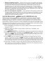
MultiMAX 7.5 is packed with new features and capabilities for the MultiMAX user
including a new Long Range Mode for remote camera triggering, which beta testers
found particularly useful in arenas and other challenging remote camera applications.
Additionally, you can now move your Custom ID to any PocketWizard frequency for
better triggering in crowded shooting environments. Multi-Zone Receive allows you to
select more then one zone for receive, useful when sharing lights.
The new Signal Strength Indicator provides a quick view of local noise levels when the
unit is turned on then switches to indicate the strength of the last trigger received.
When you need to fully understand your shooting environment, the Noise Sniffer
allows you to see the noise level on every channel. This allows you to locate potential
interference and switch channels before it becomes a problem.
There’s more and you can read the details for all new features and capabilities on the
following pages.
NEW FEATURES:
• Long Range Mode for remote camera triggering
• Close Range Mode for working at extremely close distances
• Toggle the hot shoe on and off
• Custom ID Move - put your CID on a different frequency!
• Multi-Zone Receive
• Signal Strength indicator
• Menu indicator for longer menus
• Noise Sniffer
• Radio Relay (Repeater) Mode
PocketWizard.com
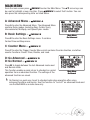
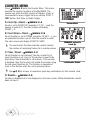
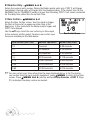
Range Menu - /MENU L A
A:RANGE MODE
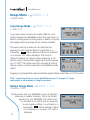
Long Range Mode -
/MENU L A A
A:LONG-LT/LR
Long range mode increases the usable distance, up to
double, between two MultiMAX radios. This new feature is
ideal for photographers shooting sports or wildlife, or anyone
who simply needs long range remote camera capability.
This mode must be activated on all radios that are
expected to work together. When it is activated on a
transmitter, LT will be displayed. When it is activated
on a receiver, -LR- will be displayed. This mode is
designed primarily for remote camera triggering. It can
also be used for remote flash triggering at shutter speeds
up to 1/125th. This mode cannot be used with the Plus II,
Sekonic meters, or flash packs with a PocketWizard radio
built in.
Engaging Long Range Mode will automatically adjust default contact time to 0.12 seconds.
NOTE: Long Range Mode is only for MultiMAX channels 17 through 32. Trigger
confirmation is not available in Long Range Mode.
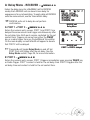
Normal Range Mode -
/MENU L A B
B:NORMAL-TX/RX
Normal mode sets your MultiMAX to work at standard
distances on regular channels. This is the default
operation for your MultiMAX. This mode must
be activated on all radios that are expected
to work together. When it is activated on a
transmitter, TX will be displayed. When
it is activated on a receiver, -RX- will be
displayed.
ii
PocketWizard.com
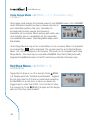
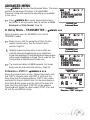
Close Range Mode -
/MENU L A C (Transmitter Only)
C:CLOSE-CT
Close range mode reduces the transmit power of your MultiMAX when it is in TRANSMIT
mode. This mode is useful if you have a receiver very close to
your transmitter (within a few feet). Normally it is
recommended to keep several feet between a
transmitter and a receiver. When working with radios very
close together, like on a basketball net, the transmitter
can overwhelm the receiver. Close Range Mode helps correct
that situation.
Close Range Mode is only set on a transmitter, not on a receiver. When it is activated
on a transmitter, CT will be displayed. The receiver must be set to Normal Range
Mode. -RX- will be displayed on the receiver. This mode is not compatible with Long
Range Mode. This mode can be used with a MultiMAX, Plus, Plus II, flash packs with
integrated PocketWizard radios or FlexTT5 as Receiver (standard channels only).
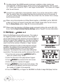
Hot Shoe Menu - /MENU L B
B:HOTSHOE OFF
Toggle the hot shoe on or off as needed. Press /MENU
L B. Display will show “Hotshoe Input Disabled”. Toggling
the hot shoe input to OFF may be useful when mounting
the MultiMAX on a cold shoe, or when you desire the
trigger input to come from PORT 1 and not the hot shoe
it is mounted in. Press /MENU L B again and the display
will read “Hot shoe Input Enabled”.
iii
PocketWizard.com
Custom ID Menu - /MENU L C
C:CUSTOM ID
This menu only appears if you have a Custom ID and you have a US/FCC radio.
What is a Custom ID? It is a private channel on a MultiMAX. In hyper-crowded
shooting environments, Custom IDs give you the confidence to know that your remote
flash or camera can only be triggered by you and not any other photographer. It is an
exclusive code installed on top of an existing PocketWizard frequency, usually
replacing Channel 17 with your new custom code and frequency combination.
No other manufacturer offers such a unique and valuable service. Because Custom IDs
require a firmware modification, this service is only available directly through LPA
Design. Contact us via our inquiries page on:
PocketWizard.com: http://www.pocketwizard.com/contact/inquiry/
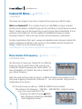
Move Custom ID Frequency -
/MENU L C A
A:CUSTOM ID FREQ
Use this menu to move your Custom IDs to a different
frequency. This is useful if there is RF noise on your
Custom ID’s default frequency (see “Noise Sniffer” for
more information) or if another user has a Custom ID on
your default frequency.
Select the Custom ID you want to move to a different frequency by pressing A or B.
Only Quad-Triggering Channel IDs (Channels 17 - 32) can be moved. Only your first 2
Custom IDs can be moved.
On the next screen you will see: SAME AS CHAN XX and a number.
The number is the frequency - 349.000 = 349.000 MHz. Using the arrow
keys, move your Custom ID to the
frequency you want and press /MENU.
Every frequency is shared by a MultiMAX
Quad-Triggering Channel.
iv
PocketWizard.com
When the display says SAME AS CHAN 21 and the frequency displayed is 348500
that means that your Custom ID will use the same frequency that is in use on standard
Channel 21 - Photographers using that channel can’t trigger you and you can’t trigger
them, but if you try to trigger at the exact same time then you may interfere with each
other and cause a loss of triggers.
View Custom ID -
/MENU L C B
B:VIEW CUSTOM ID
Displays a list of your installed Custom IDs and what
frequency they are using.
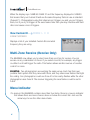
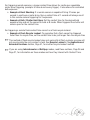
Multi-Zone Receive (Receive Only)
The MultiMAX now allows you to select more than one Zone for receive. You can
receive on any combination of Zones. If you select A and B, for example, any trigger
on either A or B will trigger the radio. This feature allows another avenue of creative
control for zones.
EXAMPLE: Two photographers are working the same venue. Each has their own
portable flash system that they move with them, and they share area flashes that light
the ceiling. One photographer could use Zone A for his nearby flashes while the other
photographer uses Zone B. The receiver triggering the area flashes could be set to
A & B.
Menu Indicator
If a menu in the MultiMAX contains more than four items, there is a now an indicator
that shows there are more choices above or below the current list. Just use the
arrow keys to see the other menu items.
v
PocketWizard.com
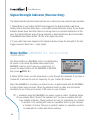
Signal Strength Indicator (Receive Only)
The Signal Indicator (antenna level bars like on a cell phone) now performs two functions:
1. Noise Meter: If your radio has NOT been triggered, the Signal Indicator will show
steady noise in the area. More bars = Good radio environment (less noise). If your Signal
Indicator shows fewer bars then there is a strong source of constant interference in the
area. The Signal Indicator will not show transient or brief interference like from another
PocketWizard user. Noise Sniffer “SLOW” scan might help there.
2. If your radio has been triggered, the Signal Indicator shows the strength of the last
trigger received. More bars = clear signal.
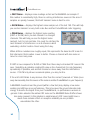
Noise Sniffer - /MENU B L (Receive Only)
L:NOISE SNIFFER
The Noise Sniffer is a MultiMAX tool for troubleshooting
RF issues. It can show the relative radio noise for the
MultiMAX channel and frequency displayed. To
access the Noise Sniffer set the MultiMAX to RECEIVE
then press /MENU B L.
In Noise Sniffer mode, use the arrow keys to cycle through the channels. If you have a
Custom ID, it will use the correct frequency for your Custom ID channel.
Place the MultiMAX in a location you intend to use, or walk around with the MultiMAX
to help pinpoint noise sources. Move the antenna closer to cable-runs and metal
structures to see if they are sources of RF noise on your channel.
127 = maximum noise the MultiMAX can sense. Lower is better. Readings below
40 are unlikely. What “should” the numbers be? As low as possible and still
have reliable operation. These numbers are only for comparing one channel
to another or for verifying RF noise as a possible factor on your channel
or location of choice. There is no perfect number, so operation needs to
be evaluated in context with these numbers.
vi
PocketWizard.com
• FAST Noise – displays noise readings as fast as the MultiMAX can sample. If
this number is consistently high, there is a strong interference source in the area. It
samples so quickly, however, that brief transient noise is hard to note.
• SLOW Noise – displays the highest noise sample out of the last 150. This will help
you see live transient or very brief noise like another PocketWizard radio triggering.
• PEAK Noise – displays the highest noise reading
(FAST or SLOW) since you last cleared it or changed
channels. This will help you see the highest noise
moment, but it is not real time. It is good for catching the
most transient of interference or as a reference when
evaluating a better location. Reset using the A key.
When all three numbers are roughly equal, this represents the base line RF noise for
that channel in that location. Lower is better. Choose a channel with less noise or
move to a less noisy area.
If FAST is low compared to SLOW or PEAK then there may be transient RF noise in the
area. Something is probably creating RF noise on the channel but it is only happening
sporadically. If possible, use another channel or move away from the interference
source. If SLOW only shows occasional spikes, you may be fine.
If the unit’s LED blinks in any manner other than the normal “powered on” blink (once
every two seconds), then the source of the noise is another PocketWizard on your frequency!
A MultiMAX mounted near the ground (within a few feet) may display a low noise
reading and still have poor performance. This is because the ground absorbs radio
energy. It absorbs the signal from your PocketWizards, so performance worsens in
general. It also absorbs the ambient RF noise so the MultiMAX Noise Sniffer shows
less noise present. In this situation a small amount of RF noise might have a
much more extreme effect on reception reliability as one problem
exacerbates the other.
vii
PocketWizard.com
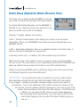
Radio Relay (Repeater) Mode (Receive Only)
This mode lets you deploy another MultiMAX to increase
your range. It receives and transmits on the same channel.
To activate Radio Relay (Repeater), set the MultiMAX to
RECEIVE on your channel of choice, then press the “L” key
twice. You should now see RPT on the display.
Pressing “L” toggles between these modes:
• RLY = Standard Camera Relay. It also displays the channel to be used when
Transmitting. This is set in TRANSMIT mode. Read more about Relay Mode in your
MultiMAX manual.
• RPT = Radio Relay (Repeater). There is no transmit channel to set in this mode. It
uses the channel as displayed in the upper right.
• No relay function (off = no display). The radio operates only as a receiver.
Make sure the zone of the repeater is set to one you are using on your transmitter.
You can use all of the other zones on your transmitting unit and the RPT MultiMAX will
relay your selected zones as long as it is also on one of the selected zones.
Deploy the repeating MultiMAX where it effectively triggers the remote unit, and can
be effectively triggered by your transmitting unit.
IMPORTANT: Do not deploy more than one repeater to cover the same remote.
Extra repeating units will step on each other and make it difficult for your remote
to get a trigger – bathing an area with repeaters is likely to worsen the remote’s
performance. You can use additional units to further increase the distance from
your remote, but each repeater should be deployed to cover only one leg of the
journey. Each repeating unit increases the radio delay by ~0.0018 seconds
(~1/800). If you are using the RPT unit for remote camera triggering,
this small delay will be unnoticeable. If you are using the RPT unit for
remote flash triggering, this may affect the fastest shutter speed you
can use.
viii
PocketWizard.com
Suggestions for remote camera triggering:
Eliminate as many RF interference issues as possible.
• Maintain a line of sight between the units.
• Keep the antennas parallel and at least 12” apart.
• Make sure the radios, and especially the antennas, are not near any large metal,
concrete, or high water-content objects. People and trees are mostly water! Make sure
they are not blocked by these objects or by hills. Crowds gathering between you and
your remotes will reduce range. Try to keep the antennas above the heads of crowds.
• PocketWizard radios will have reduced performance if deployed close to the ground.
Try to get them up high – 4 feet or higher improves range dramatically. Consider using
any miniphone/headphone extension cable (including a PocketWizard MMX cable) to
locate the receiver higher up.
• Avoid mounting them to long metal railings or other building structures.
• Avoid mounting them near long cable runs for other equipment or close to building
wiring.
• Do not wrap connecting cables around the antenna. Keep them away from the
antenna. Use right angle connectors whenever possible.
• Do not affix the radio by taping the antenna to something. Especially, do not use
duct tape or any tape containing metal fibers on the antenna.
• Avoid using long cable runs with PocketWizard radios. If you must use a long
cable run, deploy ferrite chokes (http://www.radioshack.com/product/index.
jsp?productId=2103222) near the PocketWizard end of the long run. Use more
than one ferrite choke when possible. Place them 6 to 12 inches from the
radio and from each other.
• “Dead spots” have a number of causes, but the solution is usually the
same: move the unit a few inches or feet away from the problem area.
ix
PocketWizard.com
For remote “finish line” cameras or any remote camera where a long motor
drive burst is desired, consider the following:
• Set a long contact time (for example, 1.50 seconds) on the remote receiving unit. If
range is an issue or remote operation is intermittent, this will help. If any single trigger
is received, a long burst is guaranteed. Contact time is set by pressing * B A.
• Trying to get a remote camera to trigger as fast as the master camera in your hands
by having the transmitting PocketWizard connected to the shoe or PC of the master
may be problematic. Cameras are not designed to be triggered like a high speed hot
shoe flash – for example five very short triggers in under one second. This may confuse
the remote camera, cause it to not trigger, or cause it to trigger sporadically. Instead of
relying on the shoe trigger, use either:
» A button cable (BT1 or BT3) connected to PORT 1 of the transmitting unit. Tape this button to the grip of the master camera.
» A –P cable (pre-release/pre-trigger cable) connected from the motor drive of the camera in your hands to PORT 1 of the transmitting MultiMAX. This causes the transmitting unit to be triggered as you press all the way down on your camera’s shutter release. You must use a –P cable and it must be set to OFF for this to function properly.
x
PocketWizard.com
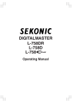
PocketWizard Utility
Your MultiMAX has a USB port which allows it to be easily updated to the latest
firmware using the PocketWizard Utility. The PocketWizard Utility can be downloaded
on our website at http://www.PocketWizard.com/support/downloads/
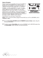
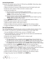
To connect your USB-enabled MultiMAX to your computer, please follow these steps:
1.
Turn off the MultiMAX radio and make sure you have fresh batteries installed.
2.
Press and hold the backlight key (located between MENU and TEST) as you turn the MultiMAX on to TRANSMIT.
3.
Note that the STATUS LED blinks steadily and the LCD remains blank. This confirms the radio is in USB mode.
4.
Make sure the PocketWizard Utility is running on your computer and no other PocketWizard radios are connected to it.
5.
Connect your MultiMAX radio to your computer using a standard Mini-B USB cable and note that your MultiMAX radio appears in the
PocketWizard Utility.
6.
To update your radio, click “Check For Updates” in the Maintenance Tab. Most updates require a full factory reset (see the RESET section on Page 29 in your MultiMAX Owner’s Manual). Be sure to write down any special settings like Contact Time, etc., before you update your radio.
Consider updating all the USB-enabled MultiMAX radios in your system to the same
firmware. Older MultiMAX radios that do not have a USB port will continue to work as
part of your MultiMAX system. The older non-USB radios cannot get the new features,
but will still perform their original functions normally when paired with USB-enabled
radios.
xi
PocketWizard.com
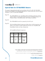
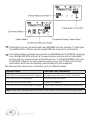
Special Note for CE MultiMAX Owners
The owner’s manual included with your purchase refers to the US (344-354 MHz)
model of the MultiMAX. The following adjustments or errata should be noted for proper
operation of your CE (433 MHz) MultiMAX:
Page 18:
The CE MultiMAX is not compatible with the following products as these products were not produced on CE frequencies: 10 Channel Classic, 16 Channel Classic, PocketWizard MAX, and Calumet TurboFilter.
Page 49:
The CE MultiMAX cannot be powered by the ACC port.
Page 50:
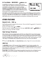
The PocketWizard Radio Frequencies table refers to USA frequencies. CE Page 50:
units
do
not operate on these frequencies and are not compatible with The PocketWizard Radio Frequencies
table refersradios
to USAon
frequencies.
CE
PocketWizard
these frequencies.
units do not operate on these
frequencies and are not compatible with
PocketWizards on these frequencies.
CE PocketWizard Radio Frequencies:
CE PocketWizard Radio Frequencies:
Channel Frequency
Unit
Digital Code
16 Bit
1 - 16
433.62
MHz
Plus or
MultiMAX
17 - 32
434.22
MHz
MultiMAX
Only
24 Bit
(20 Bit in
FAST
MODE)
Special Note Revision 1.00 (LPF205B)
© 2010 LPA Design, Inc. All rights reserved. Product features and specifications are subject to change without
notice. PocketWizard, ControlTL, MiniTT1, FlexTT5, HyperSync, Plus II and MultiMAX are either trademarks or
registered trademarks of LPA Design, Inc. All other trademarks contained herein are the property of their
respective owners.
This product is covered under a warranty. For more information on this warranty and to register your product,
please go to www.PocketWizard.com/support.
xii
US Patent: 5,359,375 and Patents Pending
LPF657 v1.0
PocketWizard.com
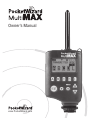
Owner’s Manual
www.PocketWizard.com
Congratulations on the purchase of your new PocketWizard
MultiMAX digital radio triggering system.
The PocketWizard MultiMAX is a microprocessor-based radio slave system
that uses advanced digital signaling to increase triggering range, reliability and
reject radio noise from other sources. Since is utilizes Transceiver technology,
it is both a transmitter and a receiver all in one. It is the most innovative and
advanced wireless solution in the photographic industry.
As a stand-alone unit, the MultiMAX offers precision special effects functions
not available in any wireless triggering device. It incorporates integrated
Trigger Time Control software, True Trigger Confirmation and Selective Quad
Triggering, all of which offer solutions to photographic challenges that hinder
today’s photographer’s creativity. Unparalleled in features and performance, the
PocketWizard MultiMAX is more than just a radio slave.
Welcome to Digital Wireless Freedom!
Manufactured in the United States of America by:
LPA Design
41 IDX Drive
Suite 265
South Burlington, VT 05403
Table of Contents
“The FCC Wants You To Know” . . . . . . . . . . . . . . . . . . . . . . . . . . . . . . . . . . . . . . 7
Icons Used in this Manual . . . . . . . . . . . . . . . . . . . . . . . . . . . . . . . . . . . . . . . . . . 8
Features . . . . . . . . . . . . . . . . . . . . . . . . . . . . . . . . . . . . . . . . . . . . . . . . . . . . . . . . 9
Communication Technology . . . . . . . . . . . . . . . . . . . . . . . . . . . . . . . . . . . . . . 9
Basic Features . . . . . . . . . . . . . . . . . . . . . . . . . . . . . . . . . . . . . . . . . . . . . . . . 9
Special Features . . . . . . . . . . . . . . . . . . . . . . . . . . . . . . . . . . . . . . . . . . . . . . . 9
Part Reference . . . . . . . . . . . . . . . . . . . . . . . . . . . . . . . . . . . . . . . . . . . . . . . . . . 10
LCD Information . . . . . . . . . . . . . . . . . . . . . . . . . . . . . . . . . . . . . . . . . . . . . . . . 11
Controls . . . . . . . . . . . . . . . . . . . . . . . . . . . . . . . . . . . . . . . . . . . . . . . . . . . . . . . 12
Power Switch . . . . . . . . . . . . . . . . . . . . . . . . . . . . . . . . . . . . . . . . . . . . . . . . 12
Keypad . . . . . . . . . . . . . . . . . . . . . . . . . . . . . . . . . . . . . . . . . . . . . . . . . . . . . 12
PORT 1 / PORT 2 . . . . . . . . . . . . . . . . . . . . . . . . . . . . . . . . . . . . . . . . . . . . . 12
Status LED . . . . . . . . . . . . . . . . . . . . . . . . . . . . . . . . . . . . . . . . . . . . . . . . . . 12
Getting Started . . . . . . . . . . . . . . . . . . . . . . . . . . . . . . . . . . . . . . . . . . . . . . . . . . 13
Safety Warnings . . . . . . . . . . . . . . . . . . . . . . . . . . . . . . . . . . . . . . . . . . . . . . 13
Battery Information . . . . . . . . . . . . . . . . . . . . . . . . . . . . . . . . . . . . . . . . . . . 13
Battery Life . . . . . . . . . . . . . . . . . . . . . . . . . . . . . . . . . . . . . . . . . . . . . . . . 14
Mounting . . . . . . . . . . . . . . . . . . . . . . . . . . . . . . . . . . . . . . . . . . . . . . . . . . . . . . 14
VELCRO® . . . . . . . . . . . . . . . . . . . . . . . . . . . . . . . . . . . . . . . . . . . . . . . . . . . 14
1/4-20 Mount . . . . . . . . . . . . . . . . . . . . . . . . . . . . . . . . . . . . . . . . . . . . . . . 14
Shoe Mount . . . . . . . . . . . . . . . . . . . . . . . . . . . . . . . . . . . . . . . . . . . . . . . . . 14
Lanyard . . . . . . . . . . . . . . . . . . . . . . . . . . . . . . . . . . . . . . . . . . . . . . . . . . . . 14
Quick Setup - Basic Radio Slave Operation . . . . . . . . . . . . . . . . . . . . . . . . . . . . 15
Basic Setup for Remote Flash . . . . . . . . . . . . . . . . . . . . . . . . . . . . . . . . . . . . 15
Triggering Multiple Flashes With Multiple RECEIVE Units . . . . . . . . . . . . . . 16
Connecting MultiMAX (set for TRANSMIT mode) to Flash . . . . . . . . . . . . . . 16
Standard Radio Operation . . . . . . . . . . . . . . . . . . . . . . . . . . . . . . . . . . . . . . . . . 17
Transceiver Control . . . . . . . . . . . . . . . . . . . . . . . . . . . . . . . . . . . . . . . . . . . . 17
Channels . . . . . . . . . . . . . . . . . . . . . . . . . . . . . . . . . . . . . . . . . . . . . . . . . . . . 17
Compatibility . . . . . . . . . . . . . . . . . . . . . . . . . . . . . . . . . . . . . . . . . . . . . . . . 18
Selective Quad-Triggering (A B C D keys) . . . . . . . . . . . . . . . . . . . . . . . . . . . 19
Classic Channels . . . . . . . . . . . . . . . . . . . . . . . . . . . . . . . . . . . . . . . . . . . 20
L Key . . . . . . . . . . . . . . . . . . . . . . . . . . . . . . . . . . . . . . . . . . . . . . . . . . . . 20
True Confirmation . . . . . . . . . . . . . . . . . . . . . . . . . . . . . . . . . . . . . . . . . . . . . 21
Radio . . . . . . . . . . . . . . . . . . . . . . . . . . . . . . . . . . . . . . . . . . . . . . . . . . . . 21
Optional Flash Confirmation Cable . . . . . . . . . . . . . . . . . . . . . . . . . . . . . . 21
Menu System . . . . . . . . . . . . . . . . . . . . . . . . . . . . . . . . . . . . . . . . . . . . . . . . . . . 23
Navigation . . . . . . . . . . . . . . . . . . . . . . . . . . . . . . . . . . . . . . . . . . . . . . . . . . 23
Numeric Entry . . . . . . . . . . . . . . . . . . . . . . . . . . . . . . . . . . . . . . . . . . . . . 24
Main Menu . . . . . . . . . . . . . . . . . . . . . . . . . . . . . . . . . . . . . . . . . . . . . . . . . . . . . 25
A: Advanced Menu . . . . . . . . . . . . . . . . . . . . . . . . . . . . . . . . . . . . . . . . . . . . 25
B: Basic Settings . . . . . . . . . . . . . . . . . . . . . . . . . . . . . . . . . . . . . . . . . . . . . 25
C: Counter Menu . . . . . . . . . . . . . . . . . . . . . . . . . . . . . . . . . . . . . . . . . . . . . 25
D: Go Advanced . . . . . . . . . . . . . . . . . . . . . . . . . . . . . . . . . . . . . . . . . . . . . . 25
D: Go Normal . . . . . . . . . . . . . . . . . . . . . . . . . . . . . . . . . . . . . . . . . . . . . . . . 25
Basic Settings . . . . . . . . . . . . . . . . . . . . . . . . . . . . . . . . . . . . . . . . . . . . . . . . . . 26
A: Contact Time . . . . . . . . . . . . . . . . . . . . . . . . . . . . . . . . . . . . . . . . . . . . . . 26
B: Beep Menu . . . . . . . . . . . . . . . . . . . . . . . . . . . . . . . . . . . . . . . . . . . . . . . . 28
A: Beep on All . . . . . . . . . . . . . . . . . . . . . . . . . . . . . . . . . . . . . . . . . . . . . . 28
B: Beep on Trigger . . . . . . . . . . . . . . . . . . . . . . . . . . . . . . . . . . . . . . . . . . 28
D: Beep Disable . . . . . . . . . . . . . . . . . . . . . . . . . . . . . . . . . . . . . . . . . . . . 28
C: LCD Contrast Adjustment . . . . . . . . . . . . . . . . . . . . . . . . . . . . . . . . . . . . . 29
D: RESET . . . . . . . . . . . . . . . . . . . . . . . . . . . . . . . . . . . . . . . . . . . . . . . . . . . 29
Counter Menu . . . . . . . . . . . . . . . . . . . . . . . . . . . . . . . . . . . . . . . . . . . . . . . . . . 30
A: Count Up + Reset . . . . . . . . . . . . . . . . . . . . . . . . . . . . . . . . . . . . . . . . . . . 30
B: Count Down + Reset . . . . . . . . . . . . . . . . . . . . . . . . . . . . . . . . . . . . . . . . 30
C: Clear / Reset . . . . . . . . . . . . . . . . . . . . . . . . . . . . . . . . . . . . . . . . . . . . . . . 30
D: Disable . . . . . . . . . . . . . . . . . . . . . . . . . . . . . . . . . . . . . . . . . . . . . . . . . . . 30
Advanced Menu . . . . . . . . . . . . . . . . . . . . . . . . . . . . . . . . . . . . . . . . . . . . . . . . . 31
A: Delay Menu - TRANSMITTER . . . . . . . . . . . . . . . . . . . . . . . . . . . . . . . . . . 31
A: Remotes + PORT 2 . . . . . . . . . . . . . . . . . . . . . . . . . . . . . . . . . . . . . . . 31
B: Remotes Only . . . . . . . . . . . . . . . . . . . . . . . . . . . . . . . . . . . . . . . . . . . 32
C: Rear Curtain . . . . . . . . . . . . . . . . . . . . . . . . . . . . . . . . . . . . . . . . . . . . . 32
A: Delay Menu - RECEIVER . . . . . . . . . . . . . . . . . . . . . . . . . . . . . . . . . . . . . 33
A: PORT 1 + PORT 2 . . . . . . . . . . . . . . . . . . . . . . . . . . . . . . . . . . . . . . . . 33
B: PORT 2 . . . . . . . . . . . . . . . . . . . . . . . . . . . . . . . . . . . . . . . . . . . . . . . . 33
C: Equalize . . . . . . . . . . . . . . . . . . . . . . . . . . . . . . . . . . . . . . . . . . . . . . . . 34
B: Intervalometer (Time Lapse Photography) . . . . . . . . . . . . . . . . . . . . . . . . 35
C: Multipop . . . . . . . . . . . . . . . . . . . . . . . . . . . . . . . . . . . . . . . . . . . . . . . . . . 36
D: SpeedCycler - TRANSMITTER . . . . . . . . . . . . . . . . . . . . . . . . . . . . . . . . . 37
D: Fast Mode - RECEIVER . . . . . . . . . . . . . . . . . . . . . . . . . . . . . . . . . . . . . . 38
Other Features . . . . . . . . . . . . . . . . . . . . . . . . . . . . . . . . . . . . . . . . . . . . . . . . . . 38
Keypad Lock . . . . . . . . . . . . . . . . . . . . . . . . . . . . . . . . . . . . . . . . . . . . . . . . . 38
High Voltage Protection . . . . . . . . . . . . . . . . . . . . . . . . . . . . . . . . . . . . . . . . 38
USB Port . . . . . . . . . . . . . . . . . . . . . . . . . . . . . . . . . . . . . . . . . . . . . . . . . . . 38
Relay Mode . . . . . . . . . . . . . . . . . . . . . . . . . . . . . . . . . . . . . . . . . . . . . . . . . 39
Software Version Display . . . . . . . . . . . . . . . . . . . . . . . . . . . . . . . . . . . . . . . 39
Applications of Advanced Functions . . . . . . . . . . . . . . . . . . . . . . . . . . . . . . . . . 40
Self-Timer or Cable Release . . . . . . . . . . . . . . . . . . . . . . . . . . . . . . . . . . . . . 40
TTL / Auto flash Helper . . . . . . . . . . . . . . . . . . . . . . . . . . . . . . . . . . . . . . . . . 40
Programmed Sequence Shooting . . . . . . . . . . . . . . . . . . . . . . . . . . . . . . . . . 41
Recycle Lockout . . . . . . . . . . . . . . . . . . . . . . . . . . . . . . . . . . . . . . . . . . . . . . 41
Camera Equalization . . . . . . . . . . . . . . . . . . . . . . . . . . . . . . . . . . . . . . . . . . . 42
Lag Time Measurement . . . . . . . . . . . . . . . . . . . . . . . . . . . . . . . . . . . . . . 43
One Unit Equalization . . . . . . . . . . . . . . . . . . . . . . . . . . . . . . . . . . . . . . . . 46
Two Unit Equalization . . . . . . . . . . . . . . . . . . . . . . . . . . . . . . . . . . . . . . . . 46
Equalization Adjustments . . . . . . . . . . . . . . . . . . . . . . . . . . . . . . . . . . . . . 48
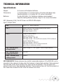
Technical Information . . . . . . . . . . . . . . . . . . . . . . . . . . . . . . . . . . . . . . . . . . . . 49
Specifications . . . . . . . . . . . . . . . . . . . . . . . . . . . . . . . . . . . . . . . . . . . . . . . . 49
Radio Information . . . . . . . . . . . . . . . . . . . . . . . . . . . . . . . . . . . . . . . . . . . . 50
Maximum and Minimum Settings . . . . . . . . . . . . . . . . . . . . . . . . . . . . . . . . 51
Saved Settings . . . . . . . . . . . . . . . . . . . . . . . . . . . . . . . . . . . . . . . . . . . . . . . 51
Troubleshooting . . . . . . . . . . . . . . . . . . . . . . . . . . . . . . . . . . . . . . . . . . . . . . . . 52
When in doubt ! . . . . . . . . . . . . . . . . . . . . . . . . . . . . . . . . . . . . . . . . . . . . . . 52
Reset to Default Factory Settings . . . . . . . . . . . . . . . . . . . . . . . . . . . . . . . . . 52
Sustaining High Performance . . . . . . . . . . . . . . . . . . . . . . . . . . . . . . . . . . . . . . 53
Time Conversion Charts . . . . . . . . . . . . . . . . . . . . . . . . . . . . . . . . . . . . . . . . . . . 54
Fractions to Decimal . . . . . . . . . . . . . . . . . . . . . . . . . . . . . . . . . . . . . . . . . . . 54
To find the correct PocketWizard brand cables for your
flash and cameras, and to experience other products like
the Plus II, please visit www.PocketWizard.com or
your local photography dealer.
T his US frequency MultiMAX is compatible with all US frequency PocketWizard products.
It is not frequency compatible with CE or JAPAN PocketWizard products. Verify frequency
compatibility before purchasing. Some products are not manufactured on every frequency.
Always operate within local radio regulations.
The FCC wants you to know:
WARNING: Changes or modifications to this unit not expressly approved by the party
responsible for compliance could void the user’s authority to operate the equipment.
NOTE: This equipment has been tested and found to comply with the limits for a Class B
digital device, pursuant to Part 15 of the FCC Rules. These limits are designed to provide
reasonable protection against harmful interference in a residential installation. This
equipment generates, uses, and can radiate radio frequency energy and, if not installed
and used in accordance with the instructions, may cause harmful interference to radio
communications.
However, there is no guarantee that interference will not occur in a particular installation. If
this equipment does cause harmful interference to radio or television reception, which can
be determined by turning the equipment off and on, the user is encouraged to try to correct
the interference by one or more of the following measures:
1. Reorient or relocate the receiving antenna.
2. Increase the separation between the equipment and the receiver.
3. Consult the dealer or an experienced radio or television technician for help.
This device complies with Part 15 of the FCC rules and also with RSS-210 of Industry
Canada. Operation is subject to the following two conditions: (1) This device may not cause
harmful interference, and (2) this device must accept any interference received, including
interference that may cause undesired operation.
Transceiver FCC ID Number: KDS-PW2-101
Transceiver Canada IC: 2170A-PW101
Icons Used in this Manual
the information following this icon. It shows important notes about the subject
N Read
being discussed.
☞ Follow this icon for more detailed information on the subject in another section.
Î Find valuable tips and techniques with this icon.
Warning or caution.
Refer to www.pocketwizard.com for updated information.
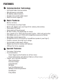
Features
Communication Technology
–
–
–
–
–
Basic Features
–
–
–
–
–
–
–
–
–
–
–
–
–
–
Full Digital Radio Communication
Microprocessor controlled
32 digitally coded channels
Complex 16 or 24 bit coded signal
Selective Quad-Triggering
Built-in hot shoe
1/4-20 female mounting thread
Built-In AC adapter jack (see Page 49 for ordering information)
Illuminated LCD panel
Illuminated soft touch keypad
60 Hours battery life (depending on usage)
Sync speeds up to 1/250 with focal plane shutter, 1/500 with leaf shutter
Fast Mode syncs up to 1/1000 with compatible cameras and flashes
Adjustable contact closure time
Compatible with all US frequency PocketWizard products (see Page 7)
Protects cameras from high sync voltage
Customizable audible beep settings
Weighs less than 5.5 ounces with batteries
USB port for future upgrades
Special Features
– Transceiver Technology
– True Confirmation
Quad-Triggering Confirmation on all four zones
Flash Confirmation with Optional Cable on all four zones
– Trigger Time Controller Software
Rear Curtain Sync
Precision Delays
Intervalometer
Multipop
Lag Time Measurement
Multiple Camera Equalization
SpeedCycler
Relay Mode
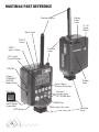
MultiMax Part Reference
Battery
Door
Latch
Flexible Antenna
¼ - 20
Tripod
Mount
Status Light
PORT 2
Output
PORT 1
Input / Output
Lanyard
Loop
LCD (Liquid
Crystal Display)
USB Port
Power /
TRANSMIT /
RECEIVE
Mode Switch
ACC Port
See page 49
for AC power
information.
TEST Button
10
Zone / Menu /
Numeric Entry Keys
Battery
Door
Channel /
Numeric Entry
UP / DOWN Keys
MENU Key
Back Light / Key Lock
Hot Shoe
Input
LCD Information
11
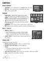
Controls
Power Switch
• TRANSMIT = Unit is powered on in TRANSMITTER (TX) mode
• RECEIVE = Unit is powered on in RECEIVER (RX) mode
• OFF = Unit is powered OFF
Power Switch
Keypad
• A B C D L = Selects Quad-Triggering Zones and
Local. Also used in menu navigation and numeric entry
• TEST = Triggers MultiMAX. Press to test operation or to
trigger remote units and/or attached cameras/flashes
•
Illuminates LCD and keypad. Hold down for key
lock. Pressing it while in any menu will bring you back
Keypad
to the Main Screen.
• /MENU = enters menus, and is used to enter or select items.
• ▲▼ Used for menu selection, selecting channels and numeric entry.
Port 1 / Port 2
• CAMERA / PORT 1 =
– Input from camera sync terminal, external trigger
button, Flash Confirmation Cable, or other device
– Output to camera motor drive, flash, or other device
• FLASH / PORT 2 = Output to flash, camera motor drive, or
other device
Status LED
Port 1, Port 2, Status LED
Displays the following information:
• Blinking every few seconds = power on, ready for trigger
• Blinking in sync with trigger = normal triggering
• Steady =
– continuously triggered from radio, hot shoe, or PORT 1
– performing delay or contact time
• Once every two seconds = performing Intervalometer or Multi-pop function
• Dark = power off or poor battery condition
12
Getting Started
Please
pay attention to the following safety warnings:
•
•
•
•
•
•
Operating temperature: above -15° C (5° F) and below 50° C (120° F)
Storage temperature, without batteries: above -30° C (-22° F) and below 85° C (185° F)
Remove batteries during storage.
Battery Requirements: IEC:LR6 (AA) Size
Do not remove instrument covers during operation.
Do not operate the device in the presence of flammable gases or fumes.
Operation of any electrical instrument in such an environment constitutes
a definite safety hazard.
• There are no user serviceable parts inside the MultiMAX. Do not install
substitute parts or perform any unauthorized modification of the instrument.
Refer servicing only to qualified and authorized personnel.
• Red LED’s are used for dim light application and do not indicate a hazardous status.
• The MultiMAX is an accessory device for cameras and flashes.
Do not use this product in a manner not specified in documentation.
Battery Information
CAUTION: Turn OFF your equipment (PocketWizard units, electronic flash
units, cameras, etc.) before making connections or changing batteries.
Install 2 fresh AA (IEC:LR6) batteries into the MultiMAX. Make sure to note
proper polarity. Alkaline batteries are recommended. Rechargeable batteries
will also work, though operation time may be reduced.
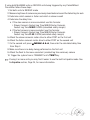
WARNING – To avoid battery leakage, follow these guidelines:
•Always remove the batteries when the unit is not in use for extended periods of time,
or during shipping or long distance travel.
• Never mix old and new batteries. Always use a fresh pair of matched batteries.
• Always change batteries promptly at the first indication of low battery operation.
• Do not use or leave the unit in extreme temperature or humidity situations.
See “Technical Information” for normal operating and storage temperatures.
rratic unit behavior or malfunction may occur if batteries are inserted while the
N Epower
switch is set to either RECEIVE or TRANSMIT. Always make sure the power
switch is set to OFF before changing or inserting batteries.
13
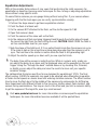
Battery Life
The MultiMAX displays remaining battery life with a 3 segment battery
icon in the upper left corner of the LCD:
3 segments displayed = batteries are fresh/new
2 segments displayed = batteries are good
1 segment displayed = replace batteries soon
0 segments displayed = install fresh/new batteries immediately
With one set of standard Alkaline batteries the MultiMAX will operate for approximately
60 hours. When using Intervalometer or Multipop modes exclusively, battery life can be
200 – 300 hours. This time may vary depending on temperature, battery type, and the
quality of batteries used. Extensive use of back light, speaker, or extended trigger contact
times will consume the batteries at a faster rate.
The MultiMAX continually regulates the battery power which gives excellent performance
throughout the life of the batteries. The unit will continue to function normally until the
batteries are nearly exhausted.
he MultiMAX voltage regulation is very efficient. There is only a small benefit when
N Tusing
Lithium batteries. Lithium batteries are designed for the quick burst high current
draw found in cameras and portable flash devices. Expect only a 10 - 20% longer
battery life (approximate) over Alkaline batteries when using Lithium batteries.
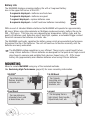
Mounting
Mount a remote MultiMAX using any of the included methods.
See Sustaining High Performance (page 53) for more mounting information.
VELCRO®
For attaching to
flashes, brackets,
cameras, etc.
Shoe Mount
For mounting on
a bracket shoe, cold
or dead shoe, etc.
14
1/4-20 Mount
For tripods,
mounting arms,
isolation bars,
brackets, etc.
Lanyard
For hanging from a
light stand, flash handle,
tripod knob, belt, etc.
Quick Setup - Basic Radio Slave Operation
Basic Setup for Remote Flash
Turn off all equipment before installing batteries or making connections!
1. Install 2 AA batteries in each MultiMAX
2. Connect camera to first MultiMAX:
a. Slide unit into camera hot shoe
- or b. Use sync cable to connect camera’s PC terminal to CAMERA / PORT 1
3. Connect flash to second MultiMAX
a. Use flash cable to connect flash unit’s sync terminal to FLASH / PORT 2
4. Turn both MultiMAX units on
a. Set power switch on MultiMAX attached to camera to TRANSMIT mode
b. Set power switch on MultiMAX attached to flash to RECEIVE mode
5. Set both MultiMAX units to same channel and Quad-Triggering zone
a. Use ▲▼ to set channel (default is CH: 17)
b. Use A B C D L to select Quad-Triggering zones
(default is TRANSMIT = A B C D L, RECEIVE = A)
6. Turn camera and flash on
7. Press TEST button on MultiMAX (set for TRANSMIT mode) and release.
Confirm remote flash triggers.
You’re all set! Use the camera normally.
15
Triggering Multiple Flashes With Multiple RECEIVE Units
Multiple remote flash units may be triggered in sync with each other.
1. Install batteries in each additional MultiMAX unit
2. Use flash cable to connect each additional flash unit’s sync terminal to FLASH / PORT 2
3. Set power switch on each additional MultiMAX unit to RECEIVE mode
4. Set all MultiMAX units to same channel as TRANSMIT unit
You’re all set! Use the camera normally.
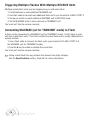
Connecting MultiMAX (set for TRANSMIT mode) to Flash
A flash can be connected to a MultiMAX (set for TRANSMIT mode). It will trigger in sync
with the remote flash units. This flash is called the local flash and is usually mounted on a
camera bracket.
1. Use a flash cable to connect the flash unit’s sync terminal to FLASH / PORT 2 of
the MultiMAX (set for TRANSMIT mode)
2. Use the L key to enable or disable the Local flash
You’re all set! Use the camera normally.
a local flash this way protects the camera from high voltages.
☞ Using
See the Specifications section, Page 49, for more information.
16
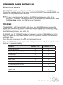
Standard Radio Operation
Transceiver Control
The MultiMAX operates as either a transmitter or a receiver. To use the MultiMAX as a
Transmitter (sending device) set the power switch to TRANSMIT. To use the MultiMAX as a
Receiver set the power switch to RECEIVE.
is a special mode that enables a MultiMAX to automatically switch from
☞ There
RECEIVE to TRANSMIT then back to RECEIVE while triggering a remote camera. Read
the Relay Mode section, Page 39, for more information.
Channels
The MultiMAX is a 32 channel digital radio slave. Each MultiMAX channel represents a
digital code transmitted on specific PocketWizard radio frequencies. This enables many
photographers to work in the same area. It also enables a photographer to control multiple
remote devices (cameras, flash units, etc).
A MultiMAX (set for TRANSMIT mode) will trigger any number of MultiMAX units (set for
RECEIVE mode) set to the same channel. Units set to different channels will not interfere
with each other.
From the main screen press the ▲▼ keys to change channels.
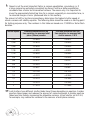
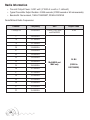
Some MultiMAX features are only available on higher channels. Refer to the table below for
features / channels availability:
Features
Channels 1-16
Channels 17-32
Digital Radio Signal.
X
X
Delay including Rear Curtain Sync
X
X
Intervalometer
X
X
Multipop
X
X
Relay Mode
X
X
Selective Quad-Triggering
X
Confirmation (Radio and Flash)
X
Fast Mode
X
SpeedCycler
X
17
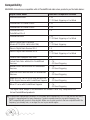
Compatibility
MultiMAX channels are compatible with all PocketWizard radio slave products per the table below:
Digital Radio Model
MultiMAX Compatible Channels
Older MultiMAX units
1-16
17-32 Quad-Triggering or Fast Mode
PocketWizard 10 Channel Classic
1-10
PocketWizard 16 Channel Classic
1-16
PocketWizard Plus
PocketWizard Plus II
1-4
PocketWizard MAX
1-16
17-32 Quad-Triggering or Fast Mode
Sekonic Digital Radio Transmitter
Module RT-32 (L358, L608, L608 CINE)
1-16
17-32 Quad-Triggering
Sekonic Digital Radio Receiver RR-4
1-4
Sekonic Digital Radio Receiver RR-32
1-16
17-32 Quad-Triggering or Fast Mode
Calumet Radio Equipped Turbo Filter
1-9
Profoto Flash Packs with built-in PocketWizard
Receivers
1 – 16
1 – 32 Quad-Triggering
Norman Flash Packs with built-in PocketWizard
Receivers
1 – 16
1 – 32 Quad-Triggering
Dyna-Lite Flash Packs with built-in PocketWizard
Receivers
1 – 16
1 – 32 Quad-Triggering
Kodak DCS Pro 14n, DCS Pro 14nx, and DCS Pro
SLR/n Digital Cameras with PocketWizard Upgrade
1 – 16
1 – 32 Quad-Triggering
Nikon D1 series with PocketWizard Upgrade
1 – 16
1 – 32 Quad-Triggering
The digital radio design of the MultiMAX will enable it to be fully compatible with
future PocketWizard products.
PocketWizard manufactures products for 3 different world frequencies: US, CE, and JAPAN. Not every
product is manufactured for every frequency. Products manufactured for one world frequency are
NOT compatible with products from another. Make sure to order products that are compatible with the
frequency you already own, or are legal for use in your world region.
18
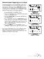
Selective Quad-Triggering (A B C D keys)
This powerful feature is used to individually control up to
4 sets of MultiMAX units (set for RECEIVE mode) on the
same channel. Each keypad letter, A B C D refers to an
individual zone. Each zone can be independently selected
or deselected from a MultiMAX (set for TRANSMIT mode).
Follow the steps below to test Quad-Triggering:
1. Set one MultiMAX to TRANSMIT mode
2. Set up to 4 MultiMAX units to RECEIVE mode (same
channel as TRANSMIT unit)
3. Using the A B C D L keys set each RECEIVE unit
to a different zone
4. On the TRANSMIT unit use the A B C D L keys to
select which zones will trigger. The zone is selected
when the letter is displayed on the LCD screen. The
zone is deselected when a dot appears where the
letter would be displayed.
5. Press the TEST key on the MultiMAX (set for
TRANSMIT mode) unit to trigger the selected zones
TRANSMIT unit
Channel: 17
Zones: A, B, and Local
RECEIVE unit
Channel: 17, Zone: A
Any number of MultiMAX units (set for RECEIVE mode)
may be set to the same channel and zone, and will
trigger simultaneously. Selective Quad-Triggering is only
available on channels 17 and higher.
RECEIVE unit
Channel: 17, Zone: B
19
Classic Channels
Classic channels are compatible with early PocketWizard
models and the PocketWizard Plus. Selective QuadTriggering is only available in channels 17 through 32. In
channels 1 through 16 the display will show CLASSIC
CHANNEL and zones A B C D do not appear. The A key
simply toggles the remote receivers on or off and is
displayed on the main screen as R. It is not possible to
toggle both the remote (A key) and the local flash (L key)
off at the same time when using a CLASSIC CHANNEL.
Operation on these channels is identical to the function of
the LOCAL / BOTH / REMOTE switch found on
PocketWizard Plus and Classic Transmitters.
TRANSMIT unit set to
CLASSIC CHANNEL 4
Remote and Local selected
L Key = On any channel the L key toggles the local flash on or off in a MultiMAX (set for
TRANSMIT mode).
the Connecting MultiMAX (set for TRANSMIT mode) to Flash section, Page 16,
☞ See
for more information.
L key toggles Relay Mode when using a MultiMAX (set for RECEIVE mode). See
☞ The
the Relay Mode section, Page 39, for more information.
20
True Confirmation
Because the MultiMAX is a true transceiver it automatically confirms triggering. It can
perform this on two levels: it confirms the round trip radio signal and can confirm actual
flash sync with an optional flash confirmation cable. It does this for all Quad-Triggering
zones on every trigger. Confirmation is indicated visually on the main screen and audibly
using beep modes.
☞ For audible confirmation settings see the Beep Menu section, Page 28.
Radio
Radio confirmation is displayed on TRANSMIT units in the A B C D area of the LCD. An
inverted letter shows an error. A normal letter shows confirmation.
During normal operation the display will show selected and active A B C D zones not
inverted. Confirmation will occur on every trigger and only in the event of an error will the
zone letters invert.
Optional Flash Confirmation Cable
Using the flash confirmation cable the MultiMAX can confirm flash sync for all four zones
on every trigger.
1. Attach flash confirmation cable to PORT 1 for each MultiMAX (set for RECEIVE mode)
2. Locate the sensor so that it can only see the flash from the correct flash unit
3. Press the TEST button on a MultiMAX (set for TRANSMIT mode) to test flash
confirmation. Correct flash confirmation is displayed on the main screen with a flash
icon to the right of each zone performing flash confirmation. In the event of an error
(either no flash was detected or the radio link was incomplete) the zone letter and the
flash icon will invert
A MultiMAX (set for TRANSMIT mode) will look for RECEIVE units and confirm the radio
link after each of these operations:
•
•
•
•
•
Every trigger
Power on or switch from RECEIVE to TRANSMIT
Channel change
Zone change (including L)
Exiting the menu system
21
onfirmation can only be performed using MultiMAX units on channels 17 and higher.
N CPocketWizard
Plus, Classic, and the original MAX do not perform confirmation.
rue Confirmation is designed to work with one MultiMAX (set for RECEIVE mode) per
N Tzone.
Multiple RECEIVE units set to the same channel and zone will not individually
confirm and may cause incorrect confirmation errors. If multiple MultiMAX units (set
for RECEIVE mode) on the same channel and zone are a mix of flash and non-flash
confirmation units then accurate flash confirmation will not be reported.
The following table shows how confirmation works in different modes:
MultiMAX Mode
Radio and Flash Confirmation
A RECEIVE unit using Selective Quad-Triggering
Provides normal radio and / or flash confirmation
A RECEIVE unit set to a Delay mode
Will not provide confirmation
A RECEIVE unit set to FAST MODE
Confirms on zone A only
A RECEIVE unit set to Intervalometer or Multipop
Provides radio confirmation before the first interval only
Note: Older MAX and MultiMAX units set to FAST MODE will not confirm on any zones.
22
Menu System
Navigation
Many functions of the MultiMAX are accessed through easy-to-navigate menus.
Press /MENU to enter the menu system. Menu items are selected by using the
A B C D L keys. You can also use the ▲▼ keys to highlight the menu item you want,
then press /MENU to select.
While within the menus the /MENU key performs two functions:
• If a menu is displayed, pressing /MENU will select the highlighted item.
Use the
key to exit the menus at any time.
• If a numeric entry is displayed, pressing /MENU stores the displayed number in
memory and proceeds to either the next input screen or the main screen depending
on mode.
Î In the next chapters many of the headings will be followed by
/MENU and some
letter combinations. These are quick references for the keys to press to get to that
function fast.
23
Numeric Entry
Several menu items require a number or value to
be entered. Numeric entry is performed with
A B C D and ▲▼ keys. The A B C D keys
each select and add 1 to a specific digit as follows:
A – selects and adds 1 to the 4th digit from the right
B – selects and adds 1 to the 3rd digit from the right
C – selects and adds 1 to the 2nd digit from the right
D – selects and adds 1 to the rightmost digit
Once a digit has been selected, use the ▲▼ keys
to adjust the number. Press and hold ▲▼ for
faster entry.
Example 1: Numeric Entry
Numbers entered in this fashion are saved when
the /MENU key is pressed and will remain
saved even after power is turned off. If the unit
is powered off while a numeric entry screen is
displayed, the displayed number will not be saved.
can also be used in Numeric Entry. In some
N Lcases,
D and L select the same digit.
perform a Lag Time Measurement, use
☞ To
Equalize Mode (see Page 34) which requires
that the MultiMAX be set for RECEIVE.
Î To quickly get to the lowest setting press and
release the A key once (selects the highest
digit) then press and hold the ▼ key.
24
Example 2: Numeric Entry
Main Menu
From the main screen press /MENU to enter the Main Menu. The ▲▼ arrow keys can
be used to highlight a menu function. Press /MENU to select that function. You can
also press the corresponding letter as listed below.
A: Advanced Menu –
/MENU A
Press A to enter the Advanced Menu. The Advanced Menu
contains Delay modes (including Rear Curtain Sync),
Intervalometer, Multipop, and SpeedCycler modes.
B: Basic Settings –
/MENU B
Press B to enter the Basic Settings menu. It contains
Contact time and Beep menu.
C: Counter Menu –
Main Menu
Go Advanced
/MENU C
Press C to enter the Trigger Counter Menu which contains Counter direction, and other
counter functions: Reset / Clear, Disable, and Load.
D: Go Advanced – /MENU D
D: Go Normal – /MENU D
Press D to toggle between the last Advanced mode used
and Normal mode.
This function enables a quick return to standard or normal
operation from an advanced function. The settings of the
advanced function are saved.
Main Menu
Go Normal
Î Go Normal is a quick way to get to standard radio slave operation after using
advanced functions and menus. Use this function to “turn off” an advanced mode and
use the MultiMAX as a radio slave only.
25
Basic Settings
Press /MENU B to enter the Basic Settings menu. Press
the corresponding letter for the setting you wish to adjust.
A: Contact Time –
/MENU B A
Contact time is the length of time that CAMERA / PORT 1
or FLASH /PORT 2 outputs remain contacted. The default
Contact Time of 0.08 is enough to trigger most camera
motor drives and flashes. Many photographers will never
need to adjust this number.
Basic Settings Menu
ontact time is how long the internal switch is held
N Cclosed.
For example, if the contact time is set to 3
seconds and a camera motor drive is attached to a
MultiMAX, when the MultiMAX triggers the camera it
will hold the contact for 3 seconds. This is identical to
pressing and holding the camera’s trigger button for
3 seconds. The contact time starts as soon as any
input is complete. Input can be from any of the
following sources: TEST button is pressed, hot shoe
is triggered, or radio trigger is received. Additional
triggers occurring during contact time are ignored.
Set Contact Time Screen
ontact time is NOT the length of time a MultiMAX (set for TRANSMIT mode) will
N Csend
a radio triggering signal. Contact time affects PORT 1 and PORT 2 only and does
not affect radio trigger transmission. Pressing and holding TEST on a MultiMAX (set
for TRANSMIT mode) will continuously send the radio trigger signal and hold the
contact on a MultiMAX (set for RECEIVE) as well as the TRANSMIT unit. When the
TEST button is released each unit’s contact time will then begin.
0.08 seconds can theoretically accommodate shooting with remote flash up to 12 FPS
(Frames Per Second), however testing with your specific equipment may be required. Setting
the Contact Time to 0.01 seconds will work with most cameras and flashes, and offers the
fastest FPS (up to 30) with some PocketWizard products.
For more information about maximum frame rates and optimum settings, please visit
the User Forum of our website at: www.pocketwizard.com
26
For triggering remote cameras, a longer contact time allows for continuous repeatable
motor drive triggering (example: 5 frame bursts every trigger). It also allows for controlled
bulb exposure.
• Example of Burst Shooting: If a remote camera is capable of firing 3 frames per
second in continuous motor drive, then a contact time of 1 second will always result
in this remote camera triggering for 3 exposures
• Example of Bulb / Shutter Held Open: Set the contact time for the desired bulb
exposure time and set the camera to bulb or B mode. When triggered the shutter will
remain open for the contact time
For triggering a remote flash contact time can act as a flash recycle lockout.
• Example of Flash Recycle Lockout: To guarantee that a flash cannot be triggered
faster then its recycle time, set the contact time to be just longer than the recycle time
method of flash recycle lockout does not work with all flash systems as some will
☞ This
not recycle while the sync contact is held. See Recycle Lockout in the Applications of
Advanced Functions section, Page 41, for another recycle lockout method.
you are using Intervalometer or Multipop modes, read these sections, Page 36 and
☞ IfPage
37, for information on these modes and how they interact with Contact Time.
27
B: Beep Menu –
/MENU B B
This menu controls the beep functions of a MultiMAX. Press
the corresponding letter to set the desired function of the built-in speaker.
A: Beep on All – /MENU B B A
MultiMAX will beep on all triggering, confirmation errors, and
zero counts as indicated below as well as on any key pressed.
B: Beep on Trigger – /MENU B B B
Beep on Trigger performs the same beeps as Beep On All
minus the double beep when the Counter hits zero in Count
Down, Multipop, or Intervalometer modes. Unit will beep
when triggered by TEST button, PORT 1, a Radio Trigger,
or the Hot Shoe per the table.
Beep Characteristic
Indicates
Single Short Beep
Indicates Proper Confirmation
Single Long Beep
Indicates Trigger Error
Single Very Short Beep
When any Key is pressed
Beep Menu
C: Beep on Zero / Error – /MENU B B C
The MultiMAX unit will not beep on normal triggering. The MultiMAX will beep only when
the counter reaches zero and on confirmation errors in the following manner:
Beep Characteristic
Indicates
Single Long Beep
Indicates Trigger Confirmation error or remote MultiMAX
(unit set for RECEIVE mode) has reached zero count
Double Long Beep
Indicates MultiMAX has reached zero count
Single Short Beep
Any Key is pressed except TEST
(set for RECEIVE mode) set to Beep on Zero / Error or set to Beep on All
☞ AwillMultiMAX
indicate a confirmation error if the unit is also set to count down and the counter
reaches zero. See the Counter section, Page 30, for more information.
D: Beep Disable – /MENU B B D
Turns off all beep functions. Unit will not beep.
28
C: LCD Contrast Adjustment –
/MENU B C
Enters the LCD Contrast Adjustment screen. Use ▲▼ to adjust the contrast. Contrast can
be affected by temperature. Setting the contrast to a middle setting is recommended for
most situations.
D: RESET -
/MENU B D
Resets the unit to factory defaults. CLEAR/RESET is performed as if you held C on power
up (see Page 52 for more information on Factory Defaults). You will be asked to Press C to
confirm. Pressing any other key (except TEST) will cancel the reset operation.
29
Counter Menu
Press /MENU C enter the Counter Menu. This menu
controls the counter functions of the MultiMAX. The
counter can show the total number of triggers. Count is
incremented on every trigger from any source: PORT 1,
TEST button, Hot Shoe, or Radio Trigger.
A: Count Up + Reset – /MENU C A
Count is set to COUNT UP (example: 0,1,2,3,...) and the
counter is reset to 0. The main screen will display
COUNT ↑: 0.
Counter Menu
B: Count Down + Reset – /MENU C B
Count direction is set to DOWN (example: 10,9,8,7,...), you
are prompted to enter a count, then the counter is reset.
The main screen will display COUNT R: XXXX
Î
T he count down function could be used to indicate
the number of remaining frames for a remote camera.
TRANSMIT unit set to
Count Up
C: Clear / Reset – /MENU C C
Count direction is not changed. Counter is reset to 0 if
count direction is set to up, or the counter is reset to the
load value if count direction is set to down. If the counter
is disabled, then this function will enable the counter using
the last count direction set. The Counter is cleared and
reset in this fashion when the unit is powered down.
Î Use
Load Counter Screen
C C as an easy to remember quick key combination for fast counter reset.
D: Disable – /MENU C D
Counter is disabled and is not displayed on the main screen. While disabled the counter
does not count.
30
Advanced Menu
Press /MENU A to enter the Advanced Menu. This menu
contains the advanced functions of the MultiMAX.
Precision timing and sequencing operations are available
in this menu.
/MENU D to cancel advanced functions
☞ Press
and return to normal mode. See the section on D:Go
RECEIVE unit
Advanced Menu
Advanced and D:Go Normal, Page 25.
A: Delay Menu – TRANSMITTER –
/MENU A A
Enters the delay menu for MultiMAX units (set for
TRANSMIT mode).
menus, with the exception of Rear Curtain,
☞ Delay
require numeric entry. See the Numeric Entry
section, Page 24.
Î All delay screens (numeric entry or rear curtain) are
instantly active and triggering can occur while these
screens are displayed. A value displayed on these screens
will be used immediately on trigger. This is useful for fine
tuning a delay or adjusting rear curtain sync.
TRANSMIT unit
Advanced Menu
maximum delay is 9.9999 seconds. For longer
☞ The
delays see the Intervalometer section, Page 35.
A: Remotes + PORT 2 – /MENU A A A
Enters the numeric entry screen. Delays the remote units
and PORT 2. Remote units and PORT 2 will fire at the
same time after the displayed delay. PORT 2 will remain
contacted for the set contact time. On the main display a
small letter D will appear over the right of the large L to
show that the Local output (PORT 2) will be delayed.
Pressing L will toggle the Local output (PORT 2) on and
off, but the small D will remain.
TRANSMIT unit
Delay Menu
TRANSMIT unit
Remotes + PORT 2 delayed
31
B: Remotes Only – /MENU A A B
Enters the numeric entry screen. Delays the Radio remote units only. PORT 2 will trigger
immediately. Remote units will trigger after the displayed delay. If the contact time for the
MultiMAX (set for TRANSMIT mode) is longer than the delay, PORT 2 will remain contacted
for the delay time rather than the contact time.
C: Rear Curtain – /MENU A A C
Enters the Rear Curtain screen. Use this mode to trigger
the flash at the end of an exposure rather than at the
beginning. In this mode both the Radio remote trigger and
PORT 2 are delayed.
Use the ▲▼ keys to set the rear curtain sync time equal
to the camera’s shutter speed. Common rear curtain sync
times are available per the table below:
Rear Curtain Screen
Rear Curtain Sync Time
Decimal Equivalent
Actual Delay Used
1/1
1 second
0.98 seconds
1/2
0.5 seconds
0.49 seconds
1/4
0.25 seconds
0.24 seconds
1/8
0.125 seconds
0.119 seconds
1/15
0.0667 seconds
0.062 seconds
1/30
0.0333 seconds
0.029 seconds
1/60
0.0167 seconds
0.014 seconds
rear curtain sync times other than the ones displayed above, or for fine tuning
☞ For
rear curtain times for your specific equipment, press /MENU to return to the main
screen. Press /MENU A A A (see the section A:Delay Remotes + PORT 2, Page
31) and adjust the delay number as needed.
32
A: Delay Menu - RECEIVER –
/MENU A A
Enters the delay menu for a MultiMAX (set for RECEIVE
mode). Each RECEIVE unit can have its own delay for
sequences or for synchronization. To easily delay all RECEIVE
units the same amount, use the Transmitter’s delay.
ECEIVE units set to delay do not perform
N Rconfirmation.
A: PORT 1 + PORT 2 – /MENU A A A
Enters the numeric entry screen. PORT 1 and PORT 2 are
delayed the same amount and trigger simultaneously after
the set delay time. Both ports remain contacted for the set
contact time. Triggers can come from either the TEST
key or a radio trigger from any PocketWizard Transmitter.
On the main display a small letter D will appear to denote
that PORT 2 will be delayed.
☞
Pressing
L will toggle Relay Mode on and off but
PORT 2 will still trigger after the set delay. See the
Relay Mode section, Page 39, for more information.
RECEIVE unit
Delay Menu
RECEIVE unit
PORT 1 + PORT 2 delayed
B: PORT 2 – /MENU A A B
Enters the numeric entry screen. PORT 1 triggers immediately upon pressing TEST key
or Radio Trigger. PORT 1 contact is held for the set delay time. PORT 2 triggers after the
set delay time and contact is held for the set contact time.
33
C: Equalize – /MENU A A C
Equalize Mode is a specialized delay mode for synchronizing multiple cameras to one flash.
This mode is designed to work with shutter speeds up to 1/125 on some cameras, but
there are many factors that could affect operation.
This is the only place where Lag Times can be measured.
☞ Read the Camera Equalization section, Page 42, before continuing.
Equalize mode is designed to be used with at least 3 MultiMAX units (set in RECEIVE
mode). Two or more MultiMAX units will be attached to cameras and one MultiMAX will be
attached to a flash unit. A MultiMAX or other PocketWizard TRANSMITTER will be used to
trigger the system.
1. Place a MultiMAX (set to RECEIVE mode) on the camera hot shoe or attach cable
from camera’s PC terminal to PORT 1
2. Attach cable from PORT 2 to camera’s motor drive. If available, use a Pre-Trigger
cable (more information in the Camera Equalization section).
3. If the Equalize Screen is not displayed then press /MENU A A C from the main
screen to enter Equalize Mode. This enters the numeric entry screen and 0.1500
seconds are displayed
4. Press the TEST key. The camera should trigger and a lag time (camera triggering
delay) will be measured and displayed. Press TEST every few seconds for 5 to 15
exposures until you see the fastest lag time (lowest number displayed) for the camera
5. Press the /MENU key to return to the main screen. A delay value will be displayed.
This number is a calculated number and will differ from the lag time you saw on the
previous screen
6. Repeat steps 1 through 5 for each camera to be equalized. Use one MultiMAX (set for
RECEIVE mode) per camera.
7. Attach a MultiMAX (set for RECEIVE mode) to a flash unit.
8. From the main screen press /MENU A A C. When the numeric entry screen appears
with 0.1500 displayed, simply press /MENU to return to the main screen. Do not adjust
the number and do NOT press TEST. The main screen will show a delay of 0.1500
9. Press TEST on any PocketWizard Transmitter to trigger this equalized system
34
B: Intervalometer (Time Lapse Photography) –
/MENU A B
Enters the Intervalometer interval setting screen.
Intervalometer can be used to trigger a flash or a camera at a
set interval (time gap between triggers) for a set number of
triggers. The interval time is set in HH:MM:SS format
(Hours:Minutes:Seconds) up to a maximum of 99:59:59.
While Intervalometer is running, it will display a count
down time until the next trigger on the main screen. Also,
TRIG will be displayed on the main screen in inverse video
as the PORTs are being triggered.
Intervalometer Mode
Set Interval Screen
1. From the main screen press /MENU A B to enter the numeric entry screen
2. Enter the interval or time gap between triggers
3. Press /MENU to proceed to the next screen
4. Enter the count or number of triggers
5. Press /MENU to return to the main screen. The interval will be displayed, and the
count will show the number of triggers to be executed.
6. Press TEST or trigger MultiMAX via Radio to begin intervalometer function
Intervalometer has two modes of operation depending on
which PORT is used:
• PORT 1 = first trigger takes place AFTER first interval
• PORT 2 = first trigger takes place BEFORE first interval
MultiMAX (set for TRANSMIT mode) does not
N Asend
interval radio triggers. The MultiMAX (set for
TRANSMIT unit
120 second Interval
TRANSMIT mode) will send out a single radio trigger
36 trigger Count
pulse at the beginning of the first interval only. It will
continue to trigger devices attached to its PORTs, but it will not send a radio trigger
for any more intervals. For remote interval operation, use interval mode on a RECEIVE
unit. Each MultiMAX (set for RECEIVE mode) may have a unique interval setting or
can be used with equal settings. Interval and count entry screens are instantly active
The Set Interval and Adjust Counter screens are instantly active. While the Set Interval
screen is displayed a change of interval will be immediately executed upon trigger either
from the TEST key or Radio trigger. The count used will be the last count set. If the
Adjust Counter screen is displayed a change of count will be immediately executed upon
trigger using the last interval set.
Î Intervalometer can be interrupted by pressing and holding the
/MENU key.
35
Î For delays longer than 9.9999 seconds (maximum available in delay modes) use
Intervalometer or Multipop mode. Set the interval to the desired delay. Set the count
to 1. Attach your camera to PORT 1 and trigger the MultiMAX . The camera will trigger
after the set interval.
ontact time is affected by Intervalometer mode. If you set an interval that is LESS
N Cthan
the contact time, the contact time becomes the interval minus 0.3 seconds. If
you set an interval that is GREATER than the contact time, the contact time is simply
performed as entered.
using Intervalometer and Relay Mode together, a MultiMAX (set for RECEIVE
☞ When
mode) will switch to Transmit mode and send a Radio trigger after the last interval.
See the Relay Mode section, Page 39, for more information.
using Intervalometer or Multipop modes exclusively, battery life can be 200 - 300
☞ When
hours. See the Reset to Default Factory Settings section, Page 52, for more information.
C: Multipop –
/MENU A C
Enters the Multipop interval setting screen. This mode is
for triggering a flash multiple times from one trigger. It
can be used during one long exposure to increase depth of
field or for special effect sequencing. The interval setting is
normally used to set a safe flash recycling time, while the
count is set to the number of flashes or “pops” desired.
Multipop is identical in function to Intervalometer with one
exception: the multipop interval range has finer resolution;
from 0.01 to 999.99 seconds in 0.01 (1/100) second
increments. This allows for finer control when setting flash
recycle time. This mode can be used for cameras or flash units.
Multi-pop Mode
Set Interval Screen
1. From the main screen press /MENU A C to
enter the numeric entry screen
2. Enter the interval or time gap between triggers
3. Press /MENU to proceed to the next screen
TRANSMIT Unit
5.00 second Multi-pop Interval
4. Enter the count or number of triggers
10 trigger Count
5. Press /MENU to return to the main screen. The
interval will be displayed, and the count will show
the number of triggers to be executed
6. Press the TEST key or trigger the MultiMAX via Radio to begin Multipop function
36
The following chart is a starting point for calculating how the number of flashes or pops
affects F-stops. Since every flash unit is different, use a light meter or other method for
more precise calculations.
Number of Pops
Stops
Number of Pops
Stops
1
Add 0 stops
6
Add 2.5 stops
2
Add 1 stop
7
Add 3 stops
3
Add 1.5 stops
8
Add 3.5 stops
4
Add 2 stops
9
Add 4 stops
ontact time is affected by Multipop mode. If the contact time is set greater than the
N CMultipop
interval, the contact time will automatically be set to interval time MINUS
0.01 seconds. This means that a remote camera or flash will remain triggered with
only a 1/100 second release between contacts. This short released time may not be
long enough to re-trigger some cameras or flash units. If this is the case, set the
contact time lower.
D: SpeedCycler - TRANSMITTER –
/MENU A D
Enables SpeedCycler mode. Use this mode to rapidly cycle
through remote flash units and trigger faster than a single
flash can recycle by using multiple flash units. It can also
be used for triggering remote cameras sequentially.
This mode only works with Quad Triggering channels (17
and higher) and two or more MAX or MultiMAX units (set
for RECEIVE mode).
TRANSMIT unit
SpeedCycler Mode
1. From the main screen press /MENU A D to
enable SpeedCycler mode on a MultiMAX (set for
A = triggered with flash
confirmation
TRANSMIT mode)
B = next zone to be triggered
2. Enable two or more remote zones
3. Set each MultiMAX (set for RECEIVE mode) to a
different zone
4. Trigger the MultiMAX (set for TRANSMIT mode). The first trigger will fire the first
zone selected, the second trigger will fire the next zone selected. The display indicates
the next zone to trigger with an arrow. Only the zone just triggered will display proper
confirmation
f L is selected then PORT 2 on the MultiMAX (set for TRANSMIT mode) will trigger
N Ievery
time and is not cycled. It will be in sync with each cycled zone.
37
D: Fast Mode - RECEIVER –
/MENU A D
The MultiMAX is designed to sync cameras and flash units at
shutters speeds up to 1/250th for most focal plane shutters (35mm)
and 1/500th for most leaf shutters. Some camera and flash
combinations are capable of fast sync speeds up to 1/1000th. The
MultiMAX (set for RECEIVE mode) is capable of operation at these
speeds in Fast Mode. Check your camera’s and flash unit’s manuals
for the maximum sync speeds allowed by your equipment.
RECEIVE unit Fast Mode
A MultiMAX (set for RECEIVE mode) in fast mode will show FAST MODE on the display. While in
this mode Quad-Triggering and Relay Mode are not available and the A B C D L keys perform no
function on a RECEIVE unit. A MultiMAX (set for TRANSMIT mode) will trigger RECEIVE units in
FAST MODE with any remote zone selected, but will perform confirmation only on zone A.
Other Features
Keypad Lock – Hold
This function prevents inadvertent key presses. Press and hold the
toggle keypad lock on or off.
All keys are locked except
key for 3 seconds to
and TEST.
While the keypad is locked pressing any of the keys, A B C D L ▲▼ or /MENU will
display the message “KEYPAD LOCKED.”
High Voltage Protection
Many electronic cameras can be damaged by high flash sync voltage. Refer to your camera’s manual
for more information. The MultiMAX protects the camera from high flash sync voltage. The MultiMAX
can accept up to 250 volts, but there is only a safe 3.1 volts present at the hot shoe or PORT 1. A camera
triggering a MultiMAX (set for TRANSMIT mode) via the hot shoe or PORT 1 only encounters 3.1 volts.
This voltage is not MultiMAX battery dependent and will not vary over the life of the batteries.
☞ See the Hot Shoe Note in the Specifications section, Page 50, for more information.
USB Port
The MultiMAX includes a USB connector that is intended for future firmware upgrades. Any
available upgrades will appear on the PocketWizard Web site www.pocketwizard.com, and can be
downloaded with a USB connecting cable (not included). Complete instructions will be published
on the website in the near future.
Please Note: The MultiMax is not configured as portable storage device; do not attempt to power
another USB device with the MultiMax. The MultiMAX cannot be powered via the USB port.
38
Relay Mode (RECEIVE Mode Only) – L
In this mode a remote camera’s motor drive is triggered by
a MultiMAX (set for RECEIVE mode). The MultiMAX then
switches to TRANSMIT mode and waits for a sync pulse
from the camera. Upon getting the sync pulse from the
camera the unit then triggers remote flash units via radio
and returns to RECEIVE mode, ready to trigger the camera
again. Using this mode it is possible, using only 3
PocketWizard units, to have complete wireless triggering.
RECEIVE unit in Relay Mode
Receives Channel 22, Zone A
Transmits Channel 20
1. Set a MultiMAX to TRANSMIT mode and select the
channel and zones for the remote flash units
2. Set the same MultiMAX to RECEIVE mode and select the channel and zone for the
remote camera. Use a different channel then the remote flash units.
3. Press L to toggle Relay Mode on. The screen will display RLY XX (where XX is the
TRANSMIT channel to be used for relay)
4. Connect the camera’s PC terminal to PORT 1 or attach the MultiMAX to the camera’s
hot shoe
5. Connect the camera’s motor drive to PORT 2
6. Trigger the MultiMAX via radio trigger. The camera’s motor drive will trigger and
the MultiMAX display will change to TRANSMIT mode. The MultiMAX will wait 1.5
seconds for a trigger from the camera. If it gets a trigger in that time it will trigger
the remote flash units and return to RECEIVE mode. If it does not get a trigger in that
time it will return to RECEIVE mode without triggering the remote units.
Software Version Display – Hold A on power up
To check the software version of the MultiMAX without resetting the unit to factory
defaults, perform the following
1. Set power switch to OFF
2. Press and hold A key
3. Continue to hold A and set the power switch to either RECEIVE or TRANSMIT
4. Release A key when software version appears
5. Use unit normally
☞ See the Reset to Default Factory Settings section, Page 52, for more information.
39
Applications of Advanced Functions
The applications below are unique ways to use the advanced functions of the MultiMAX.
Many of them require fine-tuning or adjustment to work with different camera equipment.
Always perform test exposures to insure reliable results.
Self-Timer or Cable Release
Delays, or Intervalometer and Multipop with a count of 1, can be used as a camera
timer for self portraits or as a trigger delay to reduce camera shake. Review Delay,
Intervalometer and Multipop sections for more information.
TTL / Auto flash Helper
When using an on-camera TTL flash or Automatic exposure flash with a remote flash
there may be situations where you do not want the remote flash to affect the TTL or Auto
flash sensor. The on-camera flash can underexpose by quenching early (turning off too
soon) because it measured the light from the remote flash. The reverse of this can also be
undesirable. If the remote flash is in Automatic mode, it may quench too early because it
sensed the light from the on camera flash.
Using Delay mode can help solve this problem. Follow the steps below if using a TTL or
Automatic flash attached directly to the camera:
1. Attach the camera’s PC terminal to PORT 1 on a MultiMAX (set for TRANSMIT mode)
2. Attach manual or Automatic flash to MultiMAX (set for RECEIVE mode)
3. On the MultiMAX (set for TRANSMIT mode) press /MENU A A B to enter the set
delay screen
4. Enter in a delay of 0.0020 (1/500)
5. Trigger the camera normally
The on-camera flash will trigger immediately and have enough time to complete its full
exposure. After the set delay time the remote flash will trigger. This operation is dependent
on camera sync speed and flash duration. The delay time of 0.0020 (1/500) will work with a
focal plane shutter (35mm camera) at 1/125 shutter speed and a flash duration not longer
than 1/400.
40
Use the formula below to help calculate your maximum safe shutter speed based on your
flash durations.
to the Time Conversion Charts section, Page 54, to convert fractions into
☞ Refer
decimals for the formula.
1. Add your maximum (longest) flash durations together (decimals, not fractions)
2. Add another 0.002 (focal plane) or 0.001 (leaf shutter) to compensate for shutter
travel time
3. On the Shutter Speed Conversion chart find the next highest decimal number in the
chart. The corresponding shutter speed is the fastest speed you can safely use for
this procedure
4. Set the delay time on the MultiMAX (set for TRANSMIT mode) to the same number as
your on-camera flash unit’s longest flash duration
Programmed Sequence Shooting
Traveling stroboscopic effects can be achieved by using multiple MultiMAX units (set for
RECEIVE mode) in delay mode. Set each RECEIVE unit to a different delay and trigger from
a PocketWizard. The sequence is identical on repeat triggers.
Recycle Lockout
Some flash units can be damaged if they are triggered too quickly or before they are fully
recharged. This may cause the flash to overheat. Use Multipop Mode to protect the flash by
setting a safe recycle lockout time. Follow the steps below:
1. On a MultiMAX (set for RECEIVE mode) press /MENU A C
2. Enter the desired recycle lockout time and press /MENU
3. Enter a count of 1 and press /MENU
4. Attach remote flash to PORT 2
Example: If the lockout time you entered was 3 seconds, then the remote flash could not be
triggered more than once every 3 seconds.
41
Camera Equalization
Equalization, or synchronizing multiple cameras to the same flash, requires precision
timing. Even though we perceive camera triggering activity as instantaneous, it is not. Even
the flash, which appears to provide light only for an instant, has a time duration (flash
duration) that needs to be factored into synchronization calculations.
Every camera has a delay from the time it is triggered until the shutter is fully open. The
trigger can originate from either the camera’s trigger button or via the motor drive port.
This delay is called lag time and it can be different from camera to camera and may even
vary between two cameras of the exact same model. If two cameras are triggered at exactly
the same time their shutters will be open at different moments. If one camera is attached to
a flash, the other camera’s shutter will probably not be open at the right moment to capture
the flash.
Some cameras are not suitable for equalization. For best equalization a camera must have
a consistent lag time. If a camera’s lag time varies widely or unpredictably from shot to
shot then it may not be possible to synchronize that camera. This is not a flaw of either the
camera or the MultiMAX. A varying lag time in a camera is considered acceptable operation
for the majority of photographic situations. Cameras are usually designed to respond
predictably shot to shot, but are not necessarily or specifically designed to do so with the
precision needed for equalization. Many factors can affect a camera’s lag time:
• Camera Pre-Trigger status – cameras that have a two stage trigger button (half press
“wakes up” the camera, full press triggers the camera) will probably have widely
different lag times if triggered while awake versus asleep. Cameras usually have more
consistent lag times if they are kept “awake” or Pre- Triggered. The camera will also
respond more quickly, but will consume batteries at a faster rate. Pre-Trigger cables
are available from PocketWizard for many cameras
• Camera batteries – lag times may begin to drift or slow down as the camera’s
batteries fade, especially in primarily mechanical cameras. Fresh batteries are
recommended for equalization
• Temperature and humidity – as these factors change, the mechanical parts of a
camera may move differently thus affecting lag time. A temperature increase may
decrease lag time as the camera’s internal lubricants are warmed and flow more
freely or vice versa
• Horizontal vs vertical orientation – as a camera is moved through these orientations
various mechanisms, especially shutters in focal plane cameras, will be affected
by gravity making them move differently thus affecting lag time. In general, do not
change a camera’s orientation during equalization
42
• Multiple mechanical systems – cameras that have many changeable mechanically
interacting parts (film backs, motor drives, lens shutters) are likely to have different
lag times with different hardware combinations. A leaf shutter is in the lens so
changing lenses on a leaf shutter camera will change lag time. In some medium
format cameras having the film back loaded versus unloaded can make a significant
difference. For consistent results always use the same components (lens, body, and
film back combination for example) each time
• Auto-focus and exposure computers – some auto-focus and exposure systems will
introduce widely varying lag times as lens travel and exposure calculations can take
unpredictable amounts of time. An electronic camera set to full manual generally
provides the most consistent lag times
Lag Time Measurement – /MENU A A C L (RECEIVE units only)
The first step to camera synchronization or equalization is measuring a camera’s lag time
(triggering delay). The MultiMAX can measure a camera’s lag time in most delay modes.
Knowing your camera’s lag time is critical for camera equalization, but can also be useful in
special effects, industrial, commercial, or other photography that requires critical trigger timing.
Using the information above set up your camera for best equalization performance. Attach
a MultiMAX (set for RECEIVE mode) to the camera as follows:
1. Place a MultiMAX in the camera’s hot shoe or attach a cable from the camera’s PC
terminal to PORT 1
2. Attach the cable from PORT 2 to the camera’s motor drive. If available, use a
Pre-Release cable
3. Press /MENU A A C for a standard delay mode where lag times can be measured
4. The screen should display “Set Delay Using A B C D L ▲▼ “ and show a numeric
value. Press TEST. The unit will trigger the camera and time the delay until a sync
pulse is sensed from the hot shoe or lens
5. Press TEST every few seconds to find the fastest and slowest lag times for the
camera. Usually the first press of TEST will yield a very different number from later
measurements. Ignore the first reading. 5 to 15 lag time measurements after the first
one should yield consistent results and give a gauge of the fastest and slowest times
6. Using steps 1 through 5, measure and record the fastest and slowest lag times for
each camera you wish to equalize. Subtract the fastest from the slowest and record
this number as the camera’s lag time variation
43
Î Speed is not the most important factor in camera equalization, consistency is. If
a slow camera has extremely consistent lag times it will be a better equalization
candidate than a faster but inconsistent camera. The reason why it is important to
know the approximate fastest lag time for a camera, especially an inconsistent one, is
to calculate margin of error (discussed later in this section).
The amount of drift or lag time inconsistency determines the highest shutter speed at
which a camera will reliably equalize. The following table should be used as a starting point
for testing purposes only. The numbers in this table are based on a 1/1000th or faster flash
duration.
Shutter Speed
Probable maximum safe lag
time variation for average focal
plane (35mm) camera
Probable maximum safe lag
time variation for average leaf
shutter camera, F:8.0
1/300
<=0.0003
<=0.0013
1/250
<=0.0010
<=0.0020
1/200
<=0.0020
<=0.0030
1/180
<=0.0025
<=0.0035
1/125
<=0.0050
<=0.0060
1/90
<=0.0080
<=0.0090
1/60
<=0.0137
<=0.0147
1/30
<=0.0303
<=0.0313
1/15
<=0.0637
<=0.0647
1/8
<=0.1220
<=0.1230
1/4
<=0.2470
<=0.2480
1/2
<=0.4970
<=0.4980
1
<=0.9970
<=0.9980
2
<=1.9970
<=1.9980
eaf shutters have different shutter blade travel times depending on aperture. A wider
N Laperture
takes longer and reduces the amount of variance allowed. A smaller aperture
takes less time thereby increasing the allowable variance. (A leaf shutter set to F:4.0,
for example, may reduce the variance to the same as a focal plane camera).
44
f your camera’s maximum sync speed is slower than the number listed then you must
N Iuse
the slower sync speed. Camera equalization does not give a camera faster sync
speeds than the camera is designed to handle.
For all shutters it can be assumed that a camera with faster external flash sync speeds (X
sync) will have faster shutter travel than cameras with slower X sync speeds. Faster shutter
travel times increase the allowable variance. The table above is based on the following
shutter travel times:
• Focal Plane (35mm) – 1/1000 (0.0010) to open, 1/1000 to close
• Leaf shutter at f: 8.0 – 1/2000 (0.0005) to open, 1/2000 to close
If a flash is generating light while the shutter is moving then you will see the shutter in the
exposure for focal plane shutters. You will see a loss in F stop exposure using a leaf shutter
if the flash is generating light as the shutter aperture opens or closes.
A variable flash duration will also affect these calculations. A slow flash is visible for longer
and more likely to affect exposure while the shutter is in motion. A short flash duration
reduces the likelihood of timing variances affecting the exposure.
It is difficult to measure a shutter’s travel time or a flash units duration and it usually
requires extremely expensive test equipment. Some electronic flash manufacturers print
their flash durations in their manual. The best method for understanding your equipment’s
equalization capabilities is to shoot many test exposures over a range of settings.
Recommend Equipment for the best results
• Consistent lag time cameras
• Cameras with fast sync speeds
• Electronic flash equipment with short flash duration
45
One Unit Equalization
To equalize two cameras and one flash at 1/125 with one MultiMAX, follow these steps:
1. Set the MultiMAX to RECEIVE mode
2. Measure lag times of cameras as described and record the fastest lag for each
3. Determine which camera is faster and which is slower overall
4. Determine the delay time
a. If the slow camera is more consistent use this formula:
i. Slower Camera’s Fastest Lag Time MINUS Faster Camera’s Fastest Lag Time
MINUS 0.0025 {calculated safety margin}
b. If the fast camera is more consistent use this formula:
i. Slower Camera’s Fastest Lag Time MINUS Faster Camera’s Fastest Lag Time
PLUS 0.0025 {calculated safety margin}
5. Press /MENU A A B then enter the calculated delay time from Step 4
6. Attach the slower camera’s motor drive to PORT 1
7. Attach the faster camera’s motor drive to PORT 2
8. Attach the flash to the more consistent (smallest lag time variance) camera
9. Trigger the RECEIVE unit either from the TEST key or from a TRANSMIT unit
Two Unit Equalization
Two Unit Equalization is basically the same as above, but allows the two cameras to be
more remote. The difference in calculations compensates for radio trigger delay.
1. Set one MultiMAX to RECEIVE mode, and one to TRANSMIT mode
2. Using the RECEIVE unit, measure the lag times of each camera as described above
and record the fastest lag for each
3. Determine which camera is faster and which is slower overall
4. Determine the delay time
a. If the slow camera is more consistent use this formula: Slower Camera’s Fastest Lag
Time MINUS Faster Camera’s Fastest Lag Time MINUS 0.0030 {calculated safety margin}
b. If the fast camera is more consistent use this formula: Slower Camera’s Fastest Lag
Time MINUS Faster Camera’s Fastest Lag Time PLUS 0.0020 {calculated safety margin}
5. On the RECEIVE unit press /MENU A A A. Enter the time from Step 4
6. Attach the slower camera’s motor drive to PORT 2 on the TRANSMIT unit. Do not
leave the MultiMAX (set for TRANSMIT mode) in the hot shoe or have the PC terminal
attached to PORT 1 as this may cause a looping or lock-up situation
7. Attach the faster camera’s motor drive to either PORT on the RECEIVE unit
8. Attach the flash to the more consistent (smallest lag time variance) camera
9. Trigger the system from the TRANSMIT unit’s TEST key
46
If using both MultiMAX units as RECEIVE units being triggered by any PocketWizard
Transmitter follow these steps:
1. Set both units to RECEIVE mode
2. Measure lag times of cameras as previously described and record the fastest lag for each
3. Determine which camera is faster and which is slower overall
4. Determine the delay time
a. If the slow camera is more consistent use this formula:
i. Slower Camera’s Fastest Lag Time MINUS Faster Camera’s
Fastest Lag Time MINUS 0.0025 {calculated safety margin}
b. If the fast camera is more consistent use this formula:
i. Slower Camera’s Fastest Lag Time MINUS Faster Camera’s
Fastest Lag Time PLUS 0.0025 {calculated safety margin}
5. Attach the slower camera’s motor drive to either PORT on the first unit
6. Attach the faster camera’s motor drive to either PORT on the second unit
7. On the second unit press /MENU A A A, then enter the calculated delay time
from Step 4
8. Make sure there is no delay being performed on the first unit
9. Attach the flash to the more consistent (smallest lag time variance) camera
10. Trigger the system from a TRANSMIT unit’s TEST key
4 or more units you may find it easier to use the built-in Equalize mode. See
☞ Iftheusing
Equalize section, Page 34, for more information.
47
Equalization Adjustments
With all the variable factors above it may seem that performing the math necessary for
equalization is daunting. Here are some techniques for fine- tuning or adjusting equalization
times without using specific math:
On some 35mm cameras you can gauge timing without using film. If your camera allows
triggering with the film back open you can verify synchronization visually.
1. Perform the steps above to get basic equalization started
2. Point the flash at a blank wall
3. On the camera NOT attached to the flash, set the shutter speed to 1/60
4. Open that camera’s back
5. Point the camera at the same wall as the flash
6. As the camera and flash are being triggered look through the shutter plane through
the lens at the light from the flash hitting the wall. CAUTION: MAKE SURE the flash is
set to a comfortable level for your eyes!
7. Note the shape of the light burst. If it is a perfect bright circle then the camera is in sync.
If the circle is dark or has a hard line running along one edge then the camera is not in
sync. The hard line is the shutter in motion while the flash is still generating light
8. Adjust the shutter speed up or down until you see a perfect circle
Î The delay time setting screen is instantly active. While in numeric entry mode you
can adjust the delay up or down and the displayed value will be executed on the next
trigger. Using the “through-the-back” method above or by shooting film, Polaroid,
or digital you can adjust the delay and view the results to more suit your specific
camera’s timings.
The mathematical formulas used thus far are designed for equalizing at 1/125. The final
offset number (0.0025 for example) may need to be adjusted when attempting to equalize
at faster shutter speeds or slower ones with wide lag variation cameras. The offset number
tries to move the flash burst to the middle of the exposure to compensate for drifting lag
time. Experiment with different offsets to fine tune your shutter speed, flash duration, and
camera timing combinations. Too long or short of an offset and you limit a camera’s ability
to get the exposure if the lag drifts, even by a small amount.
Î Visit www.pocketwizard.com for more information on camera specific equalization
techniques. As more information becomes available it will be posted there.
48
Technical Information
Specifications
Weight: 5.4 ounces with alkaline batteries
Dimensions: 1.4 inches deep x 2.1 inches wide x 4.0 inches tall (body only)
Flexible antenna = 2.4 inches tall. 0.3 inches in diameter
Batteries: 2 x AA (IEC:LR6), 1.5 V batteries, alkaline recommended
Read the Getting Started section, Page 13, for more information
ACC (Accessory Port):For AC Power use PW-AC-MX adapter
Input / Output Ports:
Size
3.5mm (1/8") mono miniphone
Port 1
Polarity sensitive (only connect properly wired cables!)
MAX Input Voltage = 250 VDC
MAX Input Current = 0.3 A
Port 2
Triggers in both polarities
Normal Polarity Specs:
MAX Input Voltage = 250 VDC
MAX Input Current = 4.0 A for 20 microseconds, 0.25 A continuous
Reverse Polarity Specs:
MAX Input Voltage = 200 VDC
MAX Input Current = 2.0 A for 20 microseconds
(pulse only, no continuous contact)
Port 1 and Hot Shoe
voltage present
Output Voltage = 3.1 VDC typical = safe for digital cameras
Port 1 and Hot Shoe
triggering threshold
< 2.2 VDC
PORT 1 and Hot Shoe
holding current:
0.0005 A
HOT SHOE NOTE: Some cameras may exhibit undesirable behavior if the RECEIVE unit is
mounted in the camera hot shoe when that camera is being fired remotely. Some cameras’
hot shoe and motor drive contacts may share some connections. This can cause the
camera to lock up or stop operating normally. If your camera does not function properly in
this mode then remove the unit from the camera’s hot shoe.
49
Radio Information
• Transmit Output Power: 0.001 watt (1/1000 of a watt or 1 milliwatt)
• Typical Transmitter Output Duration: 0.0005 seconds (1/2000 second or 50 microseconds)
• Bandwidth: Narrowband, 70KHz TRANSMIT, 230KHz RECEIVE
PocketWizard Radio Frequencies:
Channel
Frequency
Unit
Digital Code
1 through 16
344.04 MHz
Classic, Plus, MAX,
and MultiMAX
16 Bit
17
346.50 MHz
18
347.00 MHz
19
347.50 MHz
20
348.00 MHz
21
348.50 MHz
22
349.00 MHz
23
349.50 MHz
24
350.00 MHz
25
350.50 MHz
26
351.00 MHz
27
351.50 MHz
28
352.00 MHz
29
352.50 MHz
30
353.00 MHz
31
353.50 MHz
32
354.00 MHz
50
24 Bit
MultiMAX and
MAX only
(20 Bit in
FAST MODE)
Maximum and Minimum Settings
The following table details the maximum and minimum values allowed for each numeric
entry setting available in the MultiMAX.
Setting
Maximum
Minimum
Contact Time
999.99 seconds or
16 minutes, 39.99 seconds
.01 seconds
Delay Time
9.9999 seconds
.0001 seconds (add 0.0005 to
displayed value for RECEIVE
units triggered via radio)
Interval (Intervalometer mode)
99:59:59 (1 second shy of 4 days,
4 hours or exactly 359,999 seconds)
1 second
Interval (Multipop mode)
999.99 seconds
(16 minutes, 39.99 seconds)
.01 seconds
Count (for Load Count or
Intervalometer / Multipop)
9999
0
Intervals are probably accurate to within +/- ~2.6 seconds per day based on the precision
of the internal crystal operating at 30 parts per million.
The maximum run time for Multipop, with count set to 9999, is over 115 days.
The maximum run time for Intervalometer, with count set to 9999, is just over 114 years. You
may need to use an AC adapter for this operation as batteries are unlikely to last 114 years.
Saved Settings
Settings are saved whenever the /MENU key is pressed. The following settings are
always RESET on normal power down:
• Counter (resets to saved load value if count is ↓, resets to 0 if count is ↑)
• Rear Curtain Sync (fraction display returns to 1/1)
• Any dynamic numeric entry screen displayed as unit is powered off will default to
its previous saved setting. The screens affected are : Load counter, Delay time, and
Interval (Multipop or Intervalometer)
The following settings are saved on power down:
Channel
Beep Mode
Delay Time
Zone
Contact Time
Interval
Relay Mode
Load Count
Advanced Mode
Fast Mode
Counter Mode
51
Troubleshooting
When in doubt !
Many issues can be resolved by powering the unit off and then back on again or by
resetting to factory default settings. Before proceeding to any other troubleshooting
procedure follow these steps:
1. Set power to OFF
2. Wait 10 seconds or until display completely blanks
3. Set power to RECEIVE or TRANSMIT
Reset to Default Factory Settings
1. Set power switch to OFF
2. Press and hold C key
3. Continue to hold C and set the power switch to either RECEIVE or TRANSMIT
4. Release C key when CLEAR/RESET message appears
Default factory settings are as follows:
Channel
17
Display Contrast
Medium
Transmitter Zones
A B C D L all enabled
Delay Time
0.0100 sec
Receiver Zone
A
Equalize Calculated Time
0.1500 sec
Relay Mode
OFF
Interval Time
00:00:01
Operating mode
NORMAL
Multipop Time
1.00 sec
Contact Time
0.08 sec
Counter Mode
OFF
Beep Mode
All
Counter Load
36
Fast Mode
OFF
he following indicators may operate erratically during reset, but will return to normal
N Ioperation
when reset completes: Battery Level, Frequency Lock, Beep Mode, and Channel.
CLEAR/RESET message also displays the software version installed in the unit. To
☞ The
view just the software version without losing settings refer to the Software Version
Display section, Page 39, for more information.
52
Sustaining High Performance
Long distance performance from your
MultiMAX depends on the orientation and
position of the units.
Whenever possible, try to maintain a line
of sight between the units and keep the
antennas parallel. Make sure they are not
near any large metal, concrete, or high
water-content objects. People and trees
are mostly water! Make sure they are not
blocked by these objects or by hills.
Positioning
Best
Acceptable
Poor
Worst
Blocking Signal
Maintain at least 12" distance between
antennas. Avoid direct antenna contact
with anything metallic. “Dead spots” have a
number of causes, but the solution is usually
the same: move the unit a few inches or feet away from the problem area.
Mounting
suggestion.
Mount the remote PocketWizard so that the antenna is
completely above the top edge of the flash pack and away
from any metal (light modifiers, stands, etc.).
Î Visit www.pocketwizard.com for more troubleshooting information. As more
information becomes available it will be posted there. Be sure to check out the
Frequently Asked Questions section on the website.
53
Time Conversion Charts
Fractions to Decimal:
Here are some common photographic fractions in decimal values. All numbers are rounded
to the nearest .0001 or 1/10,000th.
times are not Rear Curtain Sync times. These are precision numbers. Rear
☞ These
Curtain Sync numbers are always less than the exact conversions. Refer to the Rear
Curtain section, Page 32, for more information.
Fraction
Decimal
Fraction
Decimal
1/2
0.5 seconds
1/180
0.0056 seconds
1/4
0.25 seconds
1/200
0.005 seconds
1/8
0.125 seconds
1/250
0.004 seconds
1/15
0.0667 seconds
1/500
0.002 seconds
1/30
0.0333 seconds
1/1000
0.001 seconds
1/60
0.0167 seconds
1/2000
0.0005 seconds
1/90
0.0111 seconds
1/4000
0.0003 seconds
1/125
0.008 seconds
1/8000
0.0001 seconds
54
55
For more information about using
your PocketWizard product visit:
www.PocketWizard.com
MultiMAX, USB version, Manual Change Revision 1.4 (LPF100)