Transcript
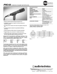
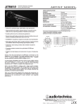
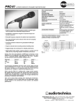
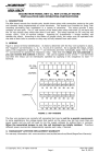
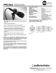
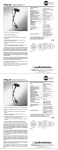
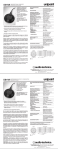
PRO 41 CARDIOID DYNAMIC MICROPHONE
PRO 41 SPECIFICATIONS†
ELEMENT
Dynamic
POLAR PATTERN
Cardioid
FREQUENCY RESPONSE
90-16,000 Hz
OPEN CIRCUIT SENSITIVITY
–55 dB (1.7 mV) re 1V at 1 Pa*
IMPEDANCE
300 ohms
SWITCH
MagnaLock™ on/off
WEIGHT (less cable and accessories)
10.7 oz (304 g)
DIMENSIONS
7.28" (185.0 mm) long,
2.09" (53.1 mm) head diameter
OUTPUT CONNECTOR
Integral 3-pin XLRM-type
CABLE
15.0' (4.5 m) cable with XLRF-type
connector at microphone end,
XLRM-type connector at equipment
end
ACCESSORIES FURNISHED
AT8470 Quiet-Flex™ stand clamp for
5
/8"-27 threaded stands;
5
/8"-27 to 3/8"-16 threaded adapter;
soft protective pouch
• Provides natural, full-range vocal reproduction
• Silent on-off operation thanks to MagnaLock™ switch design
• Hi-ENERGY® neodymium magnet for improved output and
transient response
• Two-stage ball-type screen reduces wind noise and “popping”
during close use
†In the interest of standards development, A.T.U.S. offers full details on its test
methods to other industry professionals on request.
*1 Pascal = 10 dynes /cm 2 = 10 microbars = 94 dB SPL
Specifications are subject to change without notice.
• Corrosion-resistant contacts from gold-plated XLRM-type
connectors
• Superior internal shock mounting reduces handling noise
Frequency Response
Polar Pattern
0
330
30
300
• Cardioid polar pattern reduces pickup of sounds from the sides
and rear, improving isolation of desired sound source
Output from the microphone’s XLRM-type connector is low
impedance (Lo-Z) balanced. The signal appears across Pins 2 and 3;
Pin 1 is ground (shield). Output phase is “Pin 2 hot” – positive acoustic
pressure produces positive voltage at Pin 2.
60
10 dB
90
270
240
120
50
210
180
100
500
200
1k
5k
2k
10k
20k
Frequency in Hertz
150
LEGEND
SCALE IS 5 DECIBELS PER DIVISION
12" or more on axis
LEGEND
Plug Type
XLR
1
/4" “TRS”
1
/4"
Ground
Pin 1
Sleeve
Sleeve
Audio “+”
Pin 2
Tip
Tip
Audio “–”
Pin 3
Ring
Sleeve
200 Hz
1 kHz
5 kHz
8 kHz
To avoid phase cancellation and poor sound, all mic cables must be
wired consistently: Pin 1-to-Pin 1, etc. For a high-impedance (Hi-Z) mic
input, connect a Lo-Z balanced cable to a Hi-Z matching transformer
(A-T CP8201 or equal) at the equipment input.
When using the PRO 41 in settings with a stage monitor speaker,
the speaker should be located 180° off axis (at the rear of the
microphone). This placement, in conjunction with the microphone’s
uniform cardioid pickup pattern, will virtually eliminate the possibility of
undesired audio feedback.
The PRO 41 utilizes a MagnaLock on/off switch. This specially designed
switch operates silently and may be locked in the “on” position to
prevent accidental turn-off during use. To lock, slide the switch up into
the “on” position (Fig. 1a). Using a small flat-head screwdriver, rotate
the small screw in the center of the switch 90 degrees ( 1/ 4 turn)
counter-clockwise (Fig. 1b). Never force the screw. When the screw slot
position is horizontal (“across” the microphone body), the switch is
locked. To unlock the switch, turn the screw 90 degrees clockwise until
the screw slot position is again vertical (in line with the microphone
body). Never try to turn the switch more than 90 degrees or 1/4 rotation.
The switch may only be locked in the “on” position. Do not try to turn the
screw when the switch is in the “off” position.
Unlocked
Position
Locked
Position
Do not turn
screw clockwise
to lock
Do not try
to lock switch
in the “off ”
position
OFF
ON
ON
ON
Fig. 1a
Fig. 1b
Fig.1c
Fig. 1d
Take care to keep foreign particles from entering the windscreen. An
accumulation of iron or steel filings on the diaphragm, and/or
foreign material in the windscreen’s mesh surface, can degrade
performance.
Audio-Technica U.S., Inc., 1221 Commerce Drive, Stow, Ohio 44224
Audio-Technica Limited, Old Lane, Leeds LS11 8AG England
www.audio-technica.com
P3893-00190
P51681-EN
©2004 Audio-Technica U.S., Inc.
Printed in Taiwan
Response in dB
• Rugged design and construction for reliable performance