Transcript
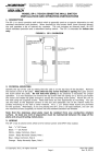
Securitron Magnalock Corp. Tel 800.624.5625 www.securitron.com [email protected] ASSA ABLOY, the global leader in door opening solutions SECURITRON MODEL RB4-12, RB4-24 RELAY BOARD INSTALLATION AND OPERATING INSTRUCTIONS 1. DESCRIPTION The RB4 board mounts four double pole, double throw relays with connection points to the coils and contacts being implemented on screw terminals. The boards are furnished on Snap Trak mounting permitting their installation in a variety of situations. The relays provide 2 Amp contacts on each pole. The 12 volt version of the board uses relays that draw 13 mA each and the 24 volt version uses relays that draw 8 mA each. The relays operate on DC only but will accept +50%, -25% of nominal voltage. Pulsating DC (transformer + bridge rectifier) will operate the relays. According to the status of jumper wires, the relays may be operated with one side of their coils in common or they may be fully isolated from each other. 2. WIRING Figure 1 shows terminal identification. As factory delivered with the four wire jumpers in place, the “negative” coil terminals (-1, -2, -3, -4) are all in common. So to operate the relays, simply apply 0 DC (negative) to any of the “-” coil terminals and then individually apply +DC to each “+” coil terminal to operate the respective relay. Note that the relays are not polarized so you can reverse this scheme if desired. +DC can be applied to any of the “-” coil terminals and then the relays can be individually operated by applying 0 DC (negative) to each “+” terminal. +1 -1 +2 -2 +3 -3 +4 -4 DC COIL INPUTS JUMPERS #1 #2 #3 #4 RELAY 1 RELAY 2 RELAY 3 RELAY 4 NO1 NO2 NO1 NO2 NO1 NO2 NO1 NO2 1A CONTACTS 1B 2A 2B 3A 3B 4A 4B NC1 NC2 NC1 NC2 NC1 NC2 NC1 NC2 1A 1B 2A 2B 3A 3B 4A 4B C1 C2 C1 C2 C1 C2 C1 C2 1A 1B 2A 2B 3A 3B 4A 4B FIGURE 1: RB-4 WIRING The four wire jumpers are normally left connected but may be cut for a special requirement. In some applications, the voltage inputs that switch on the relays may be from more than one power supply and you will not want to mix the supply voltages by putting them in common. When the associated jumper is cut, the coil terminals are totally isolated. Therefore different power sources can independently operate each relay, if desired. 3. MAGNACARE LIFETIME REPLACEMENT WARRANTY For warranty information visit: www.securitron.com/en/site/securitron/About/MagnaCare-Warranty/ © Copyright, 2011, all rights reserved Page 1 PN# 500-13900 Rev. D, 05/11