1
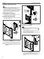
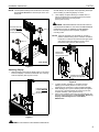
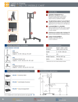
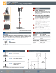
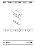
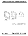
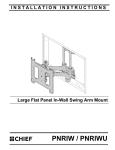
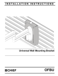
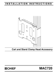
INSTALLATION INSTRUCTIONS
Instrucciones de instalación
Installationsanleitung
Instruções de Instalação
Istruzioni di installazione
Installatie-instructies
Instructions d´installation
Cart and Stand Clamp Head Accessory
Spanish Product Description
German Product Description
Portuguese Product Description
Italian Product Description
Dutch Product Description
French Product Description
PAC720
PAC720
Installation Instructions
DISCLAIMER
CSAV, Inc., and its affiliated corporations and subsidiaries
(collectively, "CSAV"), intend to make this manual accurate and
complete. However, CSAV makes no claim that the information
contained herein covers all details, conditions or variations, nor
does it provide for every possible contingency in connection
with the installation or use of this product. The information
contained in this document is subject to change without notice
or obligation of any kind. CSAV makes no representation of
warranty, expressed or implied, regarding the information
contained herein. CSAV assumes no responsibility for
accuracy, completeness or sufficiency of the information
contained in this document.
IMPORTANT WARNINGS AND
CAUTIONS!
WARNING: Failure to read, thoroughly understand, and
follow all instructions can result in serious personal injury,
damage to equipment, or voiding of factory warranty! It is the
installer’s responsibility to make sure all components are
properly assembled and installed using the instructions
provided.
WARNING: Exceeding the weight capacity can result in
serious personal injury or damage to equipment! It is the
installer’s responsibility to make sure the combined weight of
all components on the cart/stand does not exceed 200 lbs
(90.72 kg) for the PFC, 200 lbs (90.72 kg) for the PF1,
400 lbs (181.44 kg) for the PF2 [200 lbs (90.72 kg) per
faceplate].
WARNING: A WARNING alerts you to the possibility of
serious injury or death if you do not follow the instructions.
CAUTION: A CAUTION alerts you to the possibility of
damage or destruction of equipment if you do not follow the
corresponding instructions.
LEGEND
2
Tighten Fastener
Hex-Head Wrench
Apretar elemento de fijación
Llave de cabeza hexagonal
Befestigungsteil festziehen
Sechskantschlüssel
Apertar fixador
Chave de cabeça sextavada
Serrare il fissaggio
Chiave esagonale
Bevestiging vastdraaien
Zeskantsleutel
Serrez les fixations
Clé à tête hexagonale
Loosen Fastener
Phillips Screwdriver
Aflojar elemento de fijación
Destornillador Phillips
Befestigungsteil lösen
Kreuzschlitzschraubendreher
Desapertar fixador
Chave de fendas Phillips
Allentare il fissaggio
Cacciavite a stella
Bevestiging losdraaien
Kruiskopschroevendraaier
Desserrez les fixations
Tournevis à pointe cruciforme
Installation Instructions
PAC720
TOOLS REQUIRED FOR INSTALLATION AND PARTS
3/16"
(Provided)
I/M
x1
C (1)
A (1)
B (1)
D (4)
(5/16-18 x 3/4")
F (1)
3/16"
E (2)
(3/8-16)
3
PAC720
Installation Instructions
ASSEMBLY AND INSTALLATION
WARNING: EXCEEDING MAXIMUM WEIGHT CAPACITY
MAY LEAD TO SERIOUS PERSONAL INJURY OR
DAMAGE TO EQUIPMENT! It is the installer’s responsibility
to ensure the total amount of weight placed on the cart/stand
does not exceed 200 lbs (90.72 kg) for the PFC, 200 lbs
(90.72 kg) for the PF1, 400 lbs (181.44 kg) for the PF2
[200 lbs (90.72 kg) per faceplate].
(C)
PAC720 must be
installed BELOW
the knob located
on the post back.
Installing Display(s) to Cart/Stand
1.
Install display(s) to cart or stand following the installation
instructions included with the cart/stand.
Assembling Faceplate to Bracket
1.
Attach faceplate (A) to bracket (B) using two 3/8-16 Nylock
lock nuts (E). (See Figure 1)
2
(D) x 4
(PFC shown)
(A)
(B)
Figure 2
Assembly for Dual Display
WARNING: TIPPING HAZARD! Place PAC720 only on
FRONT of PFC and PF1. PAC720 may be placed on both
FRONT and BACK of PF2.
1.
1
(E) x 2
2.
Attach first faceplate (A) to bracket (B) using two 3/8-16
Nylock lock nuts (E). (See Figure 1)
Attach second faceplate (A) to bracket (B) using two 3/8-16
Nylock lock nuts (E). (See Figure 3)
2
(E) x 2
Figure 1
2.
Secure faceplate with bracket around post to clamp bracket
(C) using four 5/16-18 x 3/4" buttonhead cap screws (D).
NOTE: The faceplate assembly must be attached to the clamp
bracket below the knob on the lower part of the cart/
stand post.
(B)
(A)
Figure 3
3.
4
Secure faceplate assemblies with bracket to clamp brackets
(C) onto cart/stand post using four 5/16-18 x 3/4"
buttonhead cap screws (D) on EACH assembly. (See
Figure 4)
Installation Instructions
PAC720
40 LBS! Always use two people and proper lifting techniques
when installing or positioning display on stand.
NOTE: The faceplate assembly must be attached to the clamp
bracket below the knob on the lower part of the cart/
stand post.
2.
Lower display into place listening for audible "click" to
ensure recessed area of mounting buttons are properly
seated in lower area of mounting holes.
(See Figures 5 and 6)
WARNING: IMPROPER INSTALLATION CAN LEAD TO
PAC720 must be
installed BELOW
the knob located
on the post back.
3
CART/STAND OR DISPLAY FALLING CAUSING SERIOUS
PERSONAL INJURY OR DAMAGE TO EQUIPMENT!
Ensure mounting buttons are completely engaged in
mounting holes.
(D) x 4
NOTE: Holes are provided in the faceplate for use with a
3
padlock or similar locking device, if desired. In addition,
the pin and nut may be removed from the upper holes
and moved to the lower holes for use as a more
permanent locking device. (See Figure 6)
(D) x 4
(C)
Remove pin
1
and nut and
move to lower holes
(C)
(PF2 shown)
2
Figure 4
Attaching Display
1.
While supporting both sides of display, align four mounting
buttons on display or interface bracket with four mounting
holes in faceplate. (See Figures 5 and 6)
A padlock or bolt may
be placed through latch
holes
Figure 6
3.
PAC720 must be
installed BELOW
the knob located
on the post back.
1
4.
5.
To adjust location of display on cart/stand, support
display(s) and carefully loosen four 5/16-18 x 3/4"
buttonhead cap screws (D) on each faceplate assembly.
Slide display(s) up on post to desired position and tighten
four 5/16-18 x 3/4" buttonhead cap screws (D) for each
faceplate assembly. (See Figures 2 and 4)
Refer to the installation instructions provided with the cart/
stand for further information on Tilting Display, Removing
Display, Cable Management and Cart/Stand
Maintenance.
Figure 5
WARNING: EACH DISPLAY MAY WEIGH IN EXCESS OF
5
PAC720
Installation Instructions
USA/International
Europe
Asia Pacific
8832-000231
2007 Chief Manufacturing
www.chiefmfg.com
07/07
A
P
F
A
P
F
A
8401 Eagle Creek Parkway, Savage, MN 55378
800.582.6480 / 952.894.6280
877.894.6918 / 952.894.6918
Fellenoord 130 5611 ZB EINDHOVEN, The Netherlands
+31 40 2668620
+31 (0) 40 2668615
Room 30I, Block D, Lily YinDu International Building
LuoGang, BuJi Town, Shenzhen, CHINA. Post Code: 518112
P +86-755-8996 9226 ; 8996 9236 ; 8996 9220
F +86-755-8996 9217