1
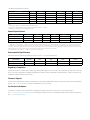
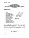
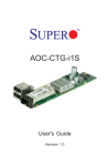
Product Brief
Intel® Ethernet SFP+ Optics
Network Connectivity
Intel® Ethernet SFP+ Optics
SR and LR Optics for the Intel® Ethernet Server Adapter X520 Family
• Hot-pluggable SFP+ footprint
• Supports rate selectable 1.25 Gb/s or 9.95 to 10.3 Gb/s bit rates
• Power dissipation < 1 W
• RoHS-6 compliant (lead-free)
• Commercial temperature range 0 °C to 70 °C
• Single 3.3 Vdc power supply
• Max. link length 300 m on 2000 MHZ-km MMF (SR), 10 km (LR)
• Uncooled 850 nm VCSEL laser (SR)
• Uncooled 1310 nm DFB laser (LR)
• Receiver limiting electrical interface
• Duplex LC connector
• Built-in digital diagnostic functions
Intel’s family of Intel® Ethernet X520 Server Adapters with SFP+
of the next-generation data center by providing unmatched
connectivity are the most flexible and scalable Ethernet adapters
features for virtualization, flexibility for LAN and SAN
for today’s demanding data center environments. The escalating
networking, and proven, reliable performance.
deployments of servers with multi-core processors and demanding
applications such as High Performance Computing (HPC), database
clusters, and video-on-demand are the types of applications driving the need for 10 Gigabit connections. Customers require flexible
and scalable I/O solutions to meet the rigorous requirements of
running mission-critical applications in virtualized and unified
storage environments.
Powered by Intel’s third-generation 10 GbE network controller,
the Intel® Ethernet 82599 10 Gigabit Ethernet Controller, the
X520 server adapter family addresses the demanding needs
To ensure maximum flexibility, Intel supports the ability to mix
any combination of the SFP+ optical modules, direct attach
copper cables, or 1000BASE-T SFP modules on the Intel Ethernet
X520 Adapters . For instance, customers can remove the optical
modules that come installed on the adapter and replace them
with an Intel® Ethernet SFP+ Optic, an SFP+ Direct Attach Copper
Cable, or a 1000BASE-T SFP module. Intel® Ethernet SFP+ Optics
are available in both short range (SR) 850 nm and long range (LR)
1310 nm options.
This enables customers to create the configuration that best
meets the needs of their data center environment.
General Specifications
Network Standards Physical Layer Interface
SR
• 1000BASE-SX 1G Ethernet
• 10GBASE-SR 10G Ethernet
LR
• 1000BASE-LX 1G Ethernet
• 10GBASE-LR 10G Ethernet
SFP+ Module Specifications
• E lectrical interface: SFF-8431 Rev 4.1
• I2C Register interface: SFF-8472 Rev 10.4
•M
echanical: SFF-8432 Rev 5.0
Product Codes
• E10GSFPSR – Intel® Ethernet SFP+ SR Optic
• E10GSFPLR – Intel® Ethernet SFP+ LR Optic
Compatible Intel® Ethernet Server Adapters
• E10G42BTDA – Intel® Ethernet Server Adapter X520-DA2
• E10G41BFSR – Intel® Ethernet Server Adapter X520-SR1*
• E10G42BFSR – Intel® Ethernet Server Adapter X520-SR2*
• E10G41BFLR – Intel® Ethernet Server Adapter X520-LR1*
* Ships with pluggable optic installed
Note: O
ther brands of SFP+ optical modules will not work with the Intel® Ethernet Server Adapter X520 Series.
Note: W
hen two Intel® Ethernet Server Adapter X520 Series SFP+ devices are connected back to back, they should be configured with the same Speed/Duplex setting.
Results may vary if speed settings are mixed.
SR
Optical Characteristics for RS0 = HIGH (10 Gb Operation)
(TOP = 0 °C to 70 °C, VCC=3.14 Vdc to 3.46 Vdc)
Parameter
Symbol
Min
Typ
Max
Unit
Note
dBm
1
Transmitter
Optical Modulation Amplitude (OMA)
P OMA
Average Launch Power
PAVE
-5
Optical Wavelength
λ
840
850
RMS Spectral Width
Δλ rms
3.0
5.5
Optical Extinction Ratio
ER
-1.5
-1
dBm
2
860
nm
1
0.45
dB
1
dB
Transmitter and Dispersion Penalty
TDP
3.9
dB
Average Launch power of OFF transmitter
P OFF
-30
dBm
Tx Jitter
Encircled Flux
Tx
Per IEEE 802.3-2008 requirements
<4.5 μm
30
%
RIN12OMA
-128
dB/Hz
Receiver Sensitivity (OMA) @ 10.3 Gb/s
R SENS1
-11.1
dBm
4
Stressed Receiver Sensitivity (OMA) @ 10.3 Gb/s
R SENS2
dBm
5
Maximum Input Power
PMAX
+0.5
λC
840
<19 μm
Relative Intensity Noise
3
86
Receiver
Wavelength Range
Receiver Reflectance
-7.5
dBm
860
nm
Rrx
-12
dB
LOS De-Assert
LOSD
-14
dBm
LOS Assert
LOSA
LOS Hysteresis
-30
-23
0.5
Notes:
1. Per Tradeoff Table 52.8, IEEE 802.3-2008
2. Average Power figures are informative only, per IEEE802.3-2008.
3. Measured into Type A1a (50/125 μm multimode) fiber per ANSI/TIA/EIA-455-203-2.
4. Measured with worst ER; BER<10-12; 231 – 1 PRBS.
5. Per IEEE 802.3-2008.
dBm
dB
SR Optical Characteristics (continued)
Parameter
Symbol
Bit Rate (RS0 = LOW)
BR
Bit Rate (RS0 = HIGH)
BR
Min
Typ
9.95
Parameter
Max
Ref.
1.25
Gb/s
1
10.3
Gb/s
2
Symbol
Max. Supported Distance
Distance
Fiber Type
Units
@ 1G
@ 10G
220
26
275
33
500
66
Units
850nm OFL Bandwidth
62.5 μm
160 MHz-km
Lmax
OM1 200 MHz-km
50 μm
400 MHz-km
OM2 500 MHz-km
Lmax
OM3 2000 MHz-km
m
550
82
>550
300
m
Notes:
1. 1
000BASE-SX. Tested with a 27 – 1 PRBS. (Transceiver data rate selected through the 2-wire bus in accordance with SFF-8472 Rev. 10.3. Soft RS0 is set at Bit3, Byte
110, Address A2h. Soft RS0 default state on power up is ‘0’ LOW, and the state is reset following a power cycle. Writing ‘1’ HIGH selects max. data rate operation. Transceiver data rate is the logic OR of the input state of the RS0 pin and soft RS0 bit. Thus, if either the RS0 pin OR the soft RS0 bit is HIGH, then the selected data rate will
be 9.95 and 10.3 Gb/s. Conversely, to select data rate 1.25 Gb/s, both the RS0 pin and the soft RS0 bit are set LOW.)
2. 1
0GBASE-SR/SW. Tested with a 231 – 1 PRBS. See note above for conditions.
Environmental Specifications
850 nm SFP transceivers have a commercial operating temperature range from 0 °C to +70 °C case temperature.
Parameter
Symbol
Min
Typ
Max
Units
Case Operating Temperature
Top
0
70
°C
Storage Temperature
Tsto
-40
85
°C
LR
Optical Characteristics for RS0 = HIGH (10 Gb Operation)
(TOP = 0 °C to 70 °C, VCC=3.14 Vdc to 3.46 Vdc)
Parameter
Symbol
Min
Typ
Max
Unit
Note
Transmitter
Optical Modulation Amplitude (OMA)
P OMA
-5.2
Average Launch Power
PAVE
-8.2
0.5
dBm
1355
nm
Optical Wavelength
Side-Mode Suppression Ratio
Optical Extinction Ratio
dBm
λ
1260
SMSR
30
dB
ER
3.5
dB
Transmitter and Dispersion Penalty
TDP
3.2
dB
Average Launch power of OFF transmitter
P OFF
-30
dBm
Tx Jitter
Tx
Relative Intensity Noise
RIN
1
Per IEEE 802.3-2008 requirements
-128
dB/Hz
Receiver
Receiver Sensitivity (OMA) @ 10.3 Gb/s
R SENS1
-12.6
dBm
2
Stressed Receiver Sensitivity (OMA) @ 10.3 Gb/s
R SENS2
-10.3
dBm
3
0.5
dBm
Average Receive Power
PAVE
-14.2
LR Optical Characteristics (continued)
Parameter
Symbol
Min
Typ
Optical Center Wavelength
λC
1260
Receiver Reflectance
Rrx
-12
dB
LOS De-Assert
LOSD
-17
dBm
LOS Assert
LOSA
-30
LOS Hysteresis
Max
Unit
1600
nm
-23
Note
dBm
0.5
dB
Notes:
1. Average power figures are informative only, per IEEE 802.3-2008.
2. Valid between 1260 and 1355 nm. Measured with worst ER; BER<10-12; 231 – 1 PRBS.
3. Valid between 1260 and 1355 nm. Per IEEE 802.3-2008.
General Specifications
Parameter
Symbol
Bit Rate (RS0 = LOW)
BR
Bit Rate (RS0 = HIGH)
BR
Max. Supported Link Length
LMAX
Min
Typ
9.95
Units
Note
1.25
Max
Gb/s
1
10.3
Gb/s
2
10
km
Notes:
1. 1000BASE-LX. Tested with a 27 – 1 PRBS. (Transceiver data rate selected through the 2-wire bus in accordance with SFF-8472 Rev. 10.3. Soft RS0 is set at Bit3, Byte
110, Address A2h. Soft RS0 default state on power up is ‘0’ LOW, and the state is reset following a power cycle. Writing ‘1’ HIGH selects max. data rate operation. Transceiver data rate is the logic OR of the input state of the RS0 pin and soft RS0 bit. Thus, if either the RS0 pin OR the soft RS0 bit is HIGH, then the selected data rate will be
9.95 and 10.3 Gb/s. Conversely, to select data rate 1.25 Gb/s, both the RS0 pin and the soft RS0 bit are set LOW.)
2. 10GBASE-LR/LW. Tested with a 231 – 1 PRBS. (See note above for conditions.)
Environmental Specifications
Transceivers have an operating temperature range from -5 °C to +70 °C case temperature.
Symbol
Min
Max
Units
Case Operating Temperature
Parameter
Top
-5
Typ
70
°C
Storage Temperature
Tsto
-40
85
°C
Regulatory Compliance
Transceivers are Class 1 Laser Products and comply with US FDA regulations. These products are certified by TÜV and CSA to meet the
Class 1 eye safety requirements of EN (IEC) 60825 and the electrical safety requirements of EN (IEC) 60950. Copies of certificates are
available from Intel Corporation upon request.
Customer Support
Intel® Customer Support Services offers a broad selection of programs including phone support and warranty service. For more information,
contact us at www.intel.com/support. Service and availability may vary by country.
For Product Information
To speak to a customer service representative regarding Intel products, please call 1-800-538-3373 (U.S. and Canada) or
visit www.intel.com/support/feedback.htm for the telephone number in your area. For additional product information on Intel products,
visit www.intel.com/go/ethernet.
To see the full line of Intel Ethernet Products, visit www.intel.com/go/ethernet.
INFORMATION IN THIS DOCUMENT IS PROVIDED IN CONNECTION WITH INTEL® PRODUCTS. NO LICENSE, EXPRESS OR IMPLIED, BY ESTOPPEL OR OTHERWISE, TO ANY INTELLECTUAL
PROPERTY RIGHTS IS GRANTED BY THIS DOCUMENT. EXCEPT AS PROVIDED IN INTEL’S TERMS AND CONDITIONS OF SALE FOR SUCH PRODUCTS, INTEL ASSUMES NO LIABILITY WHATSOEVER,
AND INTEL DISCLAIMS ANY EXPRESS OR IMPLIED WARRANTY, RELATING TO SALE AND/OR USE OF INTEL PRODUCTS INCLUDING LIABILITY OR WARRANTIES RELATING TO FITNESS FOR A
PARTICULAR PURPOSE, MERCHANTABILITY, OR INFRINGEMENT OF ANY PATENT, COPYRIGHT OR OTHER INTELLECTUAL PROPERTY RIGHT. UNLESS OTHERWISE AGREED IN WRITING BY INTEL, THE INTEL PRODUCTS ARE NOT DESIGNED NOR INTENDED FOR ANY APPLICATION IN WHICH THE FAILURE OF THE INTEL PRODUCT COULD CREATE A SITUATION WHERE PERSONAL INJURY OR DEATH MAY OCCUR.
Intel may make changes to specifications and product descriptions at any time, without notice. Designers must not rely on the absence or characteristics of any features or instructions marked “reserved” or
“undefined.” Intel reserves these for future definition and shall have no responsibility whatsoever for conflicts or incompatibilities arising from future changes to them. The information here is subject to change
without notice. Do not finalize a design with this information. The products described in this document may contain design defects or errors known as errata which may cause the product to deviate from published specifications. Current characterized errata are available on
request. Contact your local Intel sales office or your distributor to obtain the latest specifications and before placing your product order. Copies of documents which have an order number and are referenced in this document, or other Intel literature, may be obtained by calling 1-800-548-4725, or by visiting
Intel’s Web Site at http://www.intel.com.
Copyright © 2011 Intel Corporation. All rights reserved. Intel, the Intel logo, and Xeon are trademarks of Intel Corporation in the U.S. and other countries.
*Other names and brands may be claimed as the property of others.
Printed in USA
0211/TAR/SWU
Please Recycle
325067-001ENUS