1
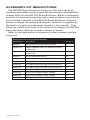
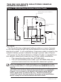
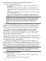
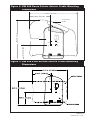
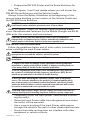
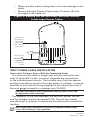
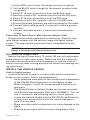
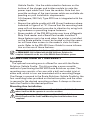
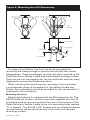
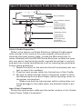
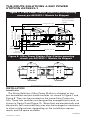
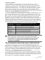
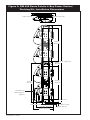
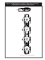
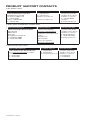
RW 420 Route Solutions
Palette
Accessory Kit Safety,
Installation
and User Guide
P1024810-101 rev. A
FEBRUARY, 2010
TABLE OF CONTENTS
RW 420 Route Solutions Accessory
Kit Safety, Installation and User
Guide....................................... EN-2
Le système RW 420 Route Solutions
Guide de sécurité, d’installation et
d’utilisation........................... FR-20
RW 420 Route Solutions-System
Sicherheits, Installations und
Benutzerhandbuch................DE-39
El sistema RW 420 Route Solutions
Guía de seguridad, instalación y uso...
ES-57
Il sistema Route Solutions RW 420
Manuale di installazione, uso e
sicurezza................................. IT-74
unidade multifuncional portátil
RW 420 Manual de segurança,
instalação e do usuário......... PT-92
P1024810-101 • EN-2
PROPRIETARY STATEMENT
This manual contains proprietary information of Zebra Technologies Corporation. It is intended solely
for the information and use of parties operating and maintaining the equipment described herein. Such
proprietary information may not be used, reproduced, or disclosed to any other parties for any other
purpose without the expressed written permission of Zebra Technologies Corporation.
Product Improvements
Since continuous product improvement is a policy of Zebra Technologies Corporation, all specifications
and signs are subject to change without notice.
FCC Compliance Statement
Class B digital device. Tested to comply with FCC standards for home or office use.
WARNING: Exposure to Radio Frequency radiation with certain versions of the printer used with this
product. To conform to FCC RF exposure requirements this device shall be used in accordance with the
operating conditions and instructions listed in the printer’s User Guide. There are several radio options
available with the printer used in conjunction with this product. Additional regulatory information is
contained in the printer’s Users Guide in sections devoted to each radio option.
NOTE: This unit was tested with shielded cables on the peripheral devices. Shielded cables must be
used with the unit to ensure compliance.
Changes or modifications to this unit not expressly approved by Zebra Technologies Corporation could
void the user’s authority to operate this equipment.
Canadian Compliance Statement
This Class B digital apparatus complies with Canadian ICES-003.
Cet appareil numérique de la classe B est conforme à la norme NMB-003 du Canada.
“IC:” before the equipment certification number signifies that the Industry Canada technical specifications were met. It does not guarantee that the certified product will operate to the user’s satisfaction.
Agency Approvals and Regulatory Information
• FCC part 15 Class B
• Canadian STD ICES-003 Class B
• EN55022:1998 Class B European Electromagnetic Radiation Standard
• EN55022:1998 European Immunity Standard
• EN60950: 2000 Safety Standard
Liability Disclaimer
Inasmuch as every effort has been made to supply accurate information in this manual, Zebra Technologies Corporation is not liable for any erroneous information or omissions. Zebra Technologies Corporation reserves the right to correct any such errors and disclaims liability resulting therefrom.
No Liability for Consequential Damage
In no event shall Zebra Technologies Corporation or anyone else involved in the creation, production,
or delivery of the accompanying product (including hardware and software) be liable for any damages
whatsoever (including, without limitation, damages for loss of business profits, business interruption,
loss of business information, or other pecuniary loss) arising out of the use of or the results of use of or
inability to use such product, even if Zebra Technologies Corporation has been advised of the possibility of such damages. Because some states do not allow the exclusion of liability for consequential or
incidental damages, the above limitation may not apply to you.
Copyrights
The copyrights in this manual and the label print engine described therein are owned by Zebra Technologies Corporation. Unauthorized reproduction of this manual or the software in the label print engine
may result in imprisonment of up to one year and fines of up to $10,000 (17 U.S.C.506). Copyright violators may be subject to civil liability.
Devices used with this product may contain ZPL®, ZPL II®, and ZebraLink™ programs; Element Energy
Equalizer® Circuit; E3®; and AGFA fonts. Software © ZIH Corp. All rights reserved worldwide.
ZebraLink and all product names and numbers are trademarks, and Zebra, the Zebra logo, ZPL, ZPL II,
Element Energy Equalizer Circuit, and E3 Circuit are registered trademarks of ZIH Corp. All rights reserved worldwide.
CG Triumvirate is a trademark of AGFA Monotype Corporation. All rights reserved worldwide.
CG Triumvirate™ font © AGFA Monotype Corporation. Intellifont® portion © AGFA Monotype Corporation. All rights reserved worldwide. UFST is a registered trademark of AGFA Monotype Corporation. All
rights reserved worldwide.
All other brand names, product names, or trademarks belong to their respective holders.
©2009 ZIH Corp
P1024810-101 • EN-3
Special Notices
The following notices emphasize certain information in this
guide. Each serves a special purpose and is displayed in the format shown:
NOTE: Note is used to emphasize any significant information.
Caution: Indicates information that, if not followed, can result in damage
to software, hardware, or data.
Caution: This symbol indicates a potentially hazardous situation which, if
not avoided, can result in personal injury.
Caution: This warning symbol indicates a potentially hazardous situation
which, if not avoided, may be a shock hazard.
Warning: This warning symbol indicates an imminently hazardous
situation which, if not avoided will result in death or serious injury.
Before you work on any equipment, be aware of the hazards involved with
electrical circuitry and be familiar with standard practices for preventing
accidents
Vehicle Installation Safety
Caution: Only trained and qualified personnel should be allowed to install,
replace, or service this equipment.
Caution: DO NOT USE THE RW 420 ROUTE SOLUTIONS WHILE DRIVING, as
this may result in property damage or personal injury. Zebra Technologies
Corp. does not promote the use of these products except when parked or
stationary, and is not responsible for any loss resulting from the use or
misuse of our products. Most importantly, we do not want to see harm
come to our customers or anyone else.
Caution: Do not install RW 420 Route Solutions where they will be exposed
to precipitation or excessive condensation.
Caution: Do not install RW 420 Route Solutions on or near an airbag cover
plate or within an airbag zone. Also, do not install RW 420 Route Solutions
in a location that will affect vehicle safety or operation.
Caution: The means of routing and securing the Power Input cable from the
RW 420 Route Solutions through to the vehicle power source is extremely
important. Hazards associated with improper wiring can be severe. To
avoid unintentional contact between the wire and any sharp edges,
provide the cable with proper bushings and clamping where it passes
through openings. If the wire is subjected to sharp surfaces and excess
engine vibration, the wiring harness insulation can wear away, causing a
short between the bare wire and the chassis. This can start a fire.
Caution: The vehicle charging circuit must neither undercharge nor
overcharge the vehicle battery. Either fault condition in the vehicle
electrical system can cause a no-charge condition in the printer battery.
P1024810-101 • EN-4
Caution: It is very important to ensure you make the correct connections
to the power source, because electrical energy from a vehicle’s power
system can harm equipment and people.
Caution: If you need to jump start your vehicle from another vehicle
battery, disconnect the power cable running to the RW 420 Route Solution.
Failure to do so can result in damage to your mobile printer and/or the RW
420 Route Solution itself.
The safety instructions in this guide do not detail every situation which could be dangerous. Common sense, caution and care
should be exercised by the user or the person in charge of the
maintenance service.
The voltage of the accessory power supply used in conjunction with
the RW 420 Route Solutions to charge batteries is high enough to be
dangerous. Maintenance and repair of electric and electronic parts must
be carried out only by qualified technicians after considering all the
necessary safety measures.
The standard RW 420 Route Solutions system is not designed to operate in
environments with a potentially explosive atmosphere.
NOTE: Zebra Technologies is not liable for personal injury or damage to
any equipment caused by the improper installation of this equipment to any
power source.
Carefully read the electric data stated on the identification
nameplate placed on the device. In case such plate is missing or
unreadable, contact a Zebra authorized service provider.
The purpose of this guide is to explain how to use and install the
RW 420 Route Solutions accessory kits by means of instructions,
pictures and examples.
All the necessary operations are described in order to allow the
correct installation and use of the RW 420 Route Solutions accessory kits.
NOTE: Always consult the user documentation supplied for the printer,
terminal and the RW 420 Route Solutions for more complete information on
the operation of these components.
Caution: Non-qualified personnel should not handle or attempt repairs of
any components of the RW 420 Route Solutions system.
P1024810-101 • EN-5
ACCESSORY KIT DESCRIPTIONS
The RW 420 Route Solutions Accessory Kits are a set of assemblies and cables which extend the functionality and flexibility
already built into the RW 420 Route Solutions. Battery recharging
circuitry for terminal and printer and communications connections
are mounted internally in the RW 420 Route Solutions. External
power to charge the printer and terminal batteries is supplied by
the family of optional accessories detailed in this manual. They
allow the installer and user of the system to configure the RW 420
Route Solutions System to meet a variety of needs.
Refer to the table below for accessory order numbers and descriptions.
Route Palette Accessory Kit Order Numbers
Order Number
Description
See pg. #
AK18822-1
RW 420 ROUTE SOLUTIONS VEHICLE CRADLE
7
AK17463-006
VEHICLE CHARGING CABLE, NO TERMINATION. MOLEX
CONNECTOR
7
AK17463-007
VEHICLE CHARGING CABLE, CIGARETTE LIGHTER. MOLEX
CONNECTOR
7
AK18865-1
KIT ACC RAM MOUNT PALETTE
13
AK18823-2
ROUTE SOLUTIONS 4 BAY POWER STATION
16
AK18828-1
2:1 CABLE FROM CRADLE TO AC ADAPTER
17
AK18474-001
KIT POWER STATION PS & CORD US (ROUTE PALETTE)
17
AK18474-005
KIT POWER STATION PS & CORD EU (ROUTE PALETTE)
17
AK18474-006
KIT POWER STATION PS & CORD UK (ROUTE PALETTE)
17
AK18913-002
KIT ACC P4T AC ADPTR NA (PRINT STATION)
17
AK18913-007
KIT ACC P4T AC ADPTR EU (PRINT STATION)
17
AK18913-006
KIT ACC P4T AC ADPTR UK (PRINT STATION)
17
P1024810-101 • EN-6
THE RW 420 ROUTE SOLUTIONS VEHICLE
CRADLE AK18822-1
Figure 1: RW 420 Route Solutions Vehicle Cradle
Mounting holes 4 places marked “A”
(see Notes)
1.19 in [3.02 cm]
10.80 in [27.4 cm]
10.80 in. [ 27.4 cm]
4.58 in [11.6 cm]
2.00 in2.00
[5.1
in. [ cm]
5.1 cm ]
2.25 in [5.7 cm]
Power Connection to
Palette
“A”
“A”
“A”
“A”“A”
“A”
“A”
“A”
1.50 in
[3.8 cm]
[ 15.2. cmcm]
]
6.036.03inin.[15.2
DC power input
Cable
Description
The Route Solutions Vehicle Cradle provides a source of power
to run and charge the RW 420 Route Solutions from the vehicle’s
electrical system. In all installations, the power cable is wired to the
vehicle’s battery power indirectly through a power take-off point.
DC power for the Route Solutions Vehicle Cradle is supplied from
the vehicle’s electrical system by one of two cable assemblies:
• The cigarette plug cable (p/n AK17463-007),
• The un-terminated power cable (p/n AK17463-006) which
must be hard-wired into the vehicle’s electrical system.
Notes: The mounting holes shown at four places “A” allow mounting to either
a surface in the vehicle, or to the optional Flexible Arm (RAM) Mount (refer to
page 13).
The orientation of the Route Solutions Vehicle Cradle as shown in Figures 1
and 2 will result in the Route Palette being mounted with its carrying handle
facing up. As a consequence, the display on the terminal and the RW 420
will be “upside down” in relation to the user. The Vehicle Cradle may be
oriented 180° from its illustrated position if the printer and terminal displays
must be read by the user when installed in the Vehicle Cradle.
continued
P1024810-101 • EN-7
INTRODUCTION TO VEHICLE CRADLE INSTALLATION
You will need the following :
• The RW 420 Route Solutions Vehicle Cradle (Zebra p/n
AK18822-1)
• One of two types of power cables running between InVehicle Storage/Charging Module and the vehicle’s power
source:
Either the un-terminated, fused power input cable (Zebra
p/n AK17463-006), or
The power input cable with a cigarette lighter adapter.
(Zebra p/n AK17463-007) The adapter is internally fused.
CAUTION: There must be a fuse between the vehicle’s power source and
the input power cable connection! If you are not using the cables provided
by Zebra for use with the RW 420 Route Solutions, selecting the size and
rating of this fuse is the installer’s responsibility. Do not replace the fuse
on either of the power input cables with a fuse with a different power
rating.
The Vehicle Cradle provides a source of power to run and
charge the RW 420 Route Solutions from the vehicle’s electrical
system. In all installations, the power cable is wired to the vehicle’s battery power indirectly through a power take-off point.
Since each situation or equipment type may pose unique
requirements, mounting hardware selection and mechanical installation shall be the responsibility of the installer. Zebra
recommends using self-locking (ESN) nuts, bolts, and/or lock
washers for installing the mount.
Since the vehicle’s electrical system is used to charge the entire
RW 420 Solutions System, it is important that this system function properly and any vehicle-generated electrical “noise” must be
minimized and within specifications.
The vehicle charging circuit must neither undercharge nor
over-charge the vehicle battery. Defective ignition wiring, damaged insulation, or faulty vehicle electrical components can cause
excess electrical noise severe enough to defeat the electrical filtering that is built into the Route Solutions system components.
NOTE: Hardware used to secure the Vehicle Cradle to the vehicle is not
supplied in the kit. Recommended fasteners are #8-32 (4 mm) socket head
bolts with flat washers, lock washers, nuts and/or locking nuts. You may
optionally elect to drill and tap for a #8-32 or M4 screw.
POSITION THE VEHICLE CRADLE
Your tasks are to:
• Route and install the input power cable to the vehicle’s
power source
• Mechanically install the Vehicle Cradle.
P1024810-101 • EN-8
Figure 2: RW 420 Route Palette Vehicle Cradle Mounting
Dimensions
13.75 in. [34.9 cm]
13.75
5.97 in. [15.2 cm]
5.97
Route Palette
Outline
12.77
12.77 in.
[32.4 cm]
Vehicle Cradle
4.58 in.4.58[11.6 cm]
“A”
“A”
“A”
“A”
Figure 3: RW 420 Print Station Vehicle Cradle Mounting
Dimensions
continued
P1024810-101 • EN-9
• Prepare the RW 420 Printer and the Route Solutions for
use.
Refer to Figures 1 and 2 and decide where you will mount the
RW 420 Route Solutions and the Vehicle Cradle.
Always follow the Safety Guidelines at the beginning of this
manual when deciding on the location of the Vehicle Cradle and
the RW 420 Route Solutions.
CAUTION: Locate the RW 420 Route Solutions system in the vehicle so that
it will avoid contact with the operator in case of an accident.
Refer to Figures 1 and 2 for Vehicle Cradle mounting dimensions. Recommended fasteners for the Mobile Charger are #8-32
[M4] bolts, flat washers and lock washers.
CAUTION: Splicing onto the input power cable is not recommended.
Voltage drops encountered across splices and other discontinuities may
reduce power to the Route Solutions to an unacceptable level.
INSTALLATION GUIDELINES
Follow the guidelines below and all other safety instructions
when installing the Input Power cables.
CAUTION: Ensure that the input power cable you are using is labeled as
appropriate for use with the vehicle’s electrical system.
NOTES: 1. It is the installer’s responsibility to ensure correct wiring and
installation.
2. Zebra is not liable for damage to any equipment caused by improper
installation or wiring of the Vehicle Cradle, or damage resulting from use
of the wrong Vehicle Cradle for the intended application.
3. Do not lengthen the input power cable. Extending the cable will affect
the systems’s reliability and radio frequency interference (RFI). Do not
attach any ground wires to the Vehicle Cradle housing.
4. Use care when attaching the converter’s power cable to the power
source. The red wire attaches to the positive (+) terminal and the black
wire to the negative (-) terminal. If wired backwards, the Vehicle Cradle
and/or the Route Solutions could be rendered inoperable and will need to
be sent to an authorized service provider for repair.
CAUTION: High voltages may be present. Always disconnect the vehicle’s
primary battery before installing any Route Solutions system component.
• Completely install the input power cable before connecting the unit(s).
• Route the Input Power cable from the general area where
the unit(s) will be mounted.
• Use a snap-in bushing if the Input Power cable passes
through the vehicle’s fire wall or other sheet-metal barriers.
• Ensure that cable routing does not interfere with other
equipment or vehicle controls.
P1024810-101 • EN-10
• Make sure that cable routing does not invite damage to the
cable.
• Secure the Input Power at least every 12 inches [30 cm]
throughout the cable run.
Figure 4: Routing the RW 420 Route Solutions Vehicle
Cradle Input Power Cables
Plug DC power
input Cable into
Vehicle Cradle
where shown,
Ensure connector
locks in place.
DC power input
Cable
AK17463-006 or
AK17463-007
Note alternate
routing
INPUT POWER CABLE INSTALLATION
Connection To Power Source With Un-Terminated Cable
You must cut the cable to length and strip the individual wire
ends of the cable. Finally, you must complete the connections
to the vehicle power source. The installer must find the nearest
practical connection point to the main battery’s voltage. It may be
possible to use internal wiring supplied in the vehicle, but only if
the wire gauge is equal to or greater than 18 AWG.
CAUTION: There must be a fuse between the vehicle’s power source and
the input power cable connection!
The capacity of the fuse between the vehicle’s power source
and the charger should not exceed 2.2A. Consult the vehicle
manufacturer or a dealer to determine the best power connection
location.
NOTE: Actual cable termination used must be compatible with the power
source. The following is only a guideline.
continued
P1024810-101 • EN-11
1. Cut the RED wire as near the power source as practical
2. Cut the BLACK wire to length to the nearest practical chassis ground.
3. Strip 1/4” (6 mm) of insulation from the BLACK wire.
4. Securely crimp a 3/8” terminal ring onto the BLACK wire.
5. Strip 1/4” (6 mm) of insulation from the RED wire.
6. Securely crimp a 3/8” terminal ring onto the RED wire.
7. Ensure that cable terminals are well connected to the cable.
8. Connect black cable ground (-) terminal to vehicle ground
location.
9. Connect red cable power (+) terminal to vehicle power
source.
Connection To Power Source With Cigarette Adapter Cable
No input power cable preparation is necessary. Plug the cigarette lighter adapter into the vehicle’s cigarette lighter power
socket. The appropriate protective fuse is integrated with the
adapter.
CAUTION: Do not attempt to replace this fuse with a higher amperage fuse.
Damage to the charger and/or the printer may result.
SECURING THE POWER CABLE
Secure the Input Power every 12 inches (30 cm) with adjustable
cable clamps or nylon wire wraps. Make sure that the cable routing does not interfere with other equipment or vehicle controls.
Ensure that the cable routing protects the cable from damage during vehicle use.
INSTALL THE VEHICLE CRADLE
Vehicle Cradle Location
Locate the Vehicle Cradle in a location that allows convenient
access to the system. Follow these guidelines:
• Allow adequate clearance for the removal and replacement
of the RW 420 Route Solutions on the Vehicle Cradle.
Refer to Figures 1 and 2 for mounting and installation dimensions .
• The Route Solutions Vehicle Cradle can also be mounted
via a flexible arm assembly (Zebra p/n AK18865-1) This option is covered in the following section of this manual.
• Locate the Vehicle Cradle and the RW 420 Route Solutions
so that it will avoid contact with the vehicle operator in
case of an accident.
• Make sure that cable routing does not invite damage to the
cable.
• Plug the power input cable into the mating plug on the
P1024810-101 • EN-12
Vehicle Cradle. Use the cable retention features on the
bottom of the charger and holder module to route the
power input cable’s exit from the module. Note that two
possible routings of the input power cable are available depending on your installation requirements.
A 5 Ampere, 250 Volt, Type 322 fuse is integrated with the
adapter.
• Secure the vehicle cradle with #8 [4 mm] hardware where
indicated in Figure 2 at “A”. Ensure that the mounting hardware will not become loose due to vibration by using locking hardware or prevailing torque fasteners.
• Some models of the RW 420 printer may have a Magnetic
Strip Card reader and a SmartCard reader installed. If
these features are to be used when the printer is installed
on the Route pallette, it must be located so that the operator will have clear access to the reader’s slots for these
cards. Refer to the RW 420 Users Guide for more information on the use of these features.
Always refer to the Safety, Installation and Use Guide (UMAN-RW4RP-101
or UMAN-RW4P-103) included with the RW 420 Route Solutions for
complete information on the use of the RW 420 Route Solutions system.
MOUNTING ARM KIT AK18865-1
Description
The optional mounting arm is offered for use with the Route
Solutions Vehicle Cradle. This kit provides a more versatile
method of positioning the RW 420 Route Solutions system. The
mounting arm consists of an arm with a ball and socket joint at
either end, which in turn are terminated with a mounting flange.
One flange is secured to the Route Solutions Vehicle Cradle by the
four mounting holes provided on the bottom plate, and the other
is secured to the desired mounting surface. A clamp on the arm
locks the Cradle in the desired position.
Mounting Arm Installation
CAUTION: Mount the Route Solutions and Route Solutions Vehicle Cradle
where it will not hit the operator in case of an accident.
Warning: Do not connect the input power cable to the Route Solutions
Vehicle Cradle until the Cradle and Mounting Arm installation have been
completed.
continued
P1024810-101 • EN-13
Figure 5: Mounting Arm Kit Dimensions
7.35”
[187 mm]
2.43” [62 mm}
R .91” [23 mm}
1.19” [30 mm}
1.50” [38 mm}
For ease of installation, the Arm can be disassembled by
loosening the clamp enough to remove the two ball and socket
flanged ends. These end flanges can then be easily secured to the
Route Solutions Vehicle Cradle and the desired mounting surface.
Then the arm can be slipped over the two ball ends and the clamp
tightened to secure the Cradle in position.
When installing the mounting arm, remember that it provides
a considerable range of movement for the Vehicle Cradle and
Printer. Extra clearance should be provided for this movement if it
is desired in the installation.
Mounting Hardware
Mounting hardware is supplied with the Mounting Arm Kit. The
#8-32 hardware (screws, washers and nuts) supplied with this kit
should be used to secure one end of the arm to the bottom of the
Route Solutions Vehicle Cradle at the four mounting holes marked
“A” in figure 2. The #10-24 x 3/4” Screws and associated hardware
may be used to secure the other end of the arm to the desired
mounting surface.
P1024810-101 • EN-14
Figure 6: Securing the Vehicle Cradle to the Mounting Arm
Route Solutions
Route Solutions Vehicle
Cradle
Use #8 hardware
supplied with kit
to secure Cradle
to Mounting Arm
Tightening Clamp
#10 hardware
supplied with
kit may be used
to secure to
mounting surface
Vehicle Cradle Preparation
Refer to the section on Route Solutions Vehicle Cradle preparation earlier in this section for more specific information on
securing the input power cable. Locate the Mounting Arm so
when installed with the RW 420 Route Solutions system the operator can easily load printing media, operate the printer’s controls
and perform routine maintenance such as cleaning the printhead.
Follow these guidelines:
1. Select a location in the vehicle that will avoid personal contact in case of an accident.
2. Plug the input power cable into the bottom of the Cradle.
3. Be sure to leave enough slack in the power cable to allow
the Mounting Arm to pivot freely without putting strain on
the power connections.
• Make sure that the input power cable routing does not
invite damage to the cable when the Vehicle Cradle is pivoted.
Input Power Completion
Route the input power cable per the earlier section in this Guide:
“Input Power Cable Completion.”
P1024810-101 • EN-15
THE ROUTE SOLUTIONS 4-BAY POWER
STATION AK18823-1
Figure 7: 4-Bay Power Station (Route Palette mounting
shown) p/n AK18823-1 Module As Shipped
28.00 in. [71.1 cm]
Charger/Holder module, 2 per assembly;
4 per kit.
28.00
“A”
4.00 in.
[10.2 cm]
12.77
“A”
2.00
0.60 in.
[1.5 cm]
2.00 in. [5.1 cm]
24.00 in. [61 cm]
24.00
3.17 in.
[8.0 cm]
“A”
4.00
10.79 in. [27.4 cm]
12.77 in. [32.4 cm]
“A”
.60
Figure 8: 4-Bay Power Station (Print Station mounting
shown) p/n AK18823-1 Module As Shipped
Bracket dimensions refer to Figure 7.
INSTALLATION
Introduction
The Route Solutions 4-Bay Power Station is shipped as two
pre-assembled and pre-wired modules, as shown in Figure 7 and
Figure 8. They can be mounted on the same 4-bay Power station. These two modules are designed be arranged end to end, as
shown in Figure 9 and Figure 10. Since they are mechanically and
electrically self-contained they may also be arranged as necessary
in other configurations, depending on the installation requirements and the space available.
continued
P1024810-101 • EN-16
Installation Options
Each module is intended to be secured at the four points
marked “A”. Due to the variety of wall surfaces that may be encountered when this kit is installed, mounting hardware is not
supplied with these kits. It is important for the installer to select
the correct hardware that will support the both weight of the
weight of the charging module assembly and the load of installing
and removing the RW 420 Route Solutions.
Prior to installing the Route Solutions 4-Bay Power Station, you
must install the proper A.C. Power cord appropriate for your region. Each AC cord in the following table will have one AC input
plug and two output receptacles that will plug into the power
supplies already installed on the 4-Bay Power Station modules as
shipped. Plug these receptacles into each of the power supplies
and arrange the cables in the mounting channels so that they will
not be pinched or crushed when the channels are secured.
Available AC Power Cables for the Route Solutions 4-Bay Power Station
Order Number
Description
AK18474-001
KIT POWER STATION PS & CORD US (ROUTE PALETTE)
AK18474-005
KIT POWER STATION PS & CORD EU (ROUTE PALETTE)
AK18474-006
KIT POWER STATION PS & CORD UK (ROUTE PALETTE)
AK18913-002
KIT ACC P4T AC ADPTR NA (PRINT STATION)
AK18913-007
KIT ACC P4T AC ADPTR EU (PRINT STATION)
AK18913-006
KIT ACC P4T AC ADPTR UK (PRINT STATION)
NOTES: 1.The selection of correct mounting hardware and power cord used with the 4-Bay Power Station kit is the responsibility of the installer.
2. The internal cable connecting the DC output of the power adapter to (2)
Vehicle Cradles is installed as part of the 4-Bay Power Station modules
as shipped. In case of damage during installation it may be ordered
separately as p/n AK18828-1.
USE OF THE ROUTE SOLUTIONS 4-BAY POWER STATION
The Route Solutions 4-Bay Power Station system allows the
simultaneous charging of up to four RW 420 Route Solutions
Systems. Its intended use is for the overnight charging of multiple
route solutions systems in preparation for their use on the next
work shift. Refer to the Route Solutions Manual for complete information on charging functions and indicatorsl.
You must ensure that the AC circuits used to power the 4-Bay
Route Solutions Power Station have adequate capacity to power
your 4-Bay Power Station installation, and that the power will not
be turned off if overnight charging is intended.
continued
P1024810-101 • EN-17
Figure
Figure 9:
9: RW
RW 420
420 Route
Route Palette
Palette 4-Bay
4-Bay Power
Power Station/
Station/
Docking
KitInstallation
Dimensions
Docking Kit- Installation Dimensions
1.56
1.56 in. [4.0 cm]
6.86
6.86 in. [17.4 cm]
24.00
24.00 in.
[61.0 cm]
4.00
4.00 in. 57.2 in. [145.3 cm]
[10.2 cm]
24.00
24.00 in.
[61.0 cm]
28.00
28.00 in.
[71.1 cm]
AC Power Cord
(refer to table on
page 17)
2.00
2.00 in. [5.1 cm]
.60
4.00 in. [10.2 cm]
10.79 in. [27.4 cm]
12.77
12.77 in. [32.4 cm]
P1024810-101 • EN-18
0.60 in. [1.5 cm]
3.69 in. [9.4 cm]
Figure 10: RW 420 Print Station 4-Bay Power Station/
Docking Kit- Installation Dimensions
Bracket dimensions refer to Figure 9 and Figure 7.
P1024810-101 • EN-19
PRODUCT SUPPORT CONTACTS
In the Americas contact
Regional Headquarters
Zebra Technologies Corporation
475 Half Day Road, Suite 500
Lincolnshire, IL 60069, U.S.A
T: +1 847 634 6700
Toll-free +1 800 423 0422
F: +1 847 913 8766
Technical Support
T: +1 847 913 2259
F: +1 847 913 2578
Hardware: [email protected]
Software: [email protected]
Customer Service Dept.
For printers, parts, media,
and ribbon, please call your
distributor, or contact us.
T: +1 877 ASK ZEBRA
(275 9327)
E: [email protected]
In Europe, Africa, the Middle East, and India contact
Regional Headquarters
Zebra Technologies Europe Limited
Dukes Meadow
Millboard Road
Bourne End
Buckinghamshire,SL8 5XF, UK
T: +44 (0) 1628 556000
F: +44 (0) 1628 556001
Technical Support
Self Service Knowledgebase:
www.zebra.com/knowledgebase
E-mail Back Technical Library: Send
e-mail to:
[email protected]
Subject: Emaillist
Internal Sales Dept.
For printers, parts, media,
and ribbon, please call your
distributor, or contact us.
T: +44 (0) 1494 768316
F: +44 (0) 1494 768244
E: [email protected]
On-Line case registration:
www.zebra.com/techrequest
In the Asia Pacific region contact
Regional Headquarters
Zebra Technologies Asia Pacific, LLC
Go to www.zebra.com/contact for complete
contact information.
T: +65 6858 0722
F: +65 6885 0838
P1024810-101 • EN-20
Technical Support
T: +65 6858 0722
F: +65 6885 0838
E: [email protected]
Customer Service
For printers, parts, media,
and ribbon, please call your
distributor, or contact us.
T: +65 6858 0722
F: +65 6885 0837
Zebra Technologies Corporation
475 Half Day Road, Suite 500
Lincolnshire, IL 60069, U.S.A