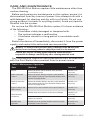
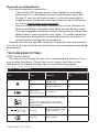
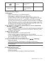
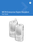
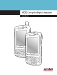
1
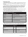
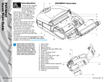
RW 420 Print Station Safety,
Installation and User Guide.... EN-2
Le système RW 420 Print Station
Guide de sécurité, d’installation et
d’utilisation............................FR-21
RW 420 Print Station-System
Sicherheits, Installations und
Benutzerhandbuch................DE-40
El sistema RW 420 Print Station
Guía de seguridad, instalación y
uso......................................... ES-59
Il sistema Print Station RW 420
Manuale di installazione, uso e
sicurezza................................. IT-78
unidade multifuncional portátil
RW 420 Manual de segurança,
instalação e do usuário......... PT-97
UMAN-RW4PS-101 rev. A
December, 2009
RW 420 PRINT STATION
SAFETY, INSTALLATION AND USER GUIDE
TABLE OF CONTENTS
PROPRIETARY STATEMENT.........................................EN-3
DESCRIPTION............................................................... EN-7
GETTING READY TO PRINT..........................................EN-9
SMART BATTERY....................................................................................... EN-9
LOADING THE MEDIA............................................................................. EN-10
OPERATOR CONTROLS......................................................................... EN-10
VERIFY THE PRINTER IS WORKING..................................................... EN-15
CONNECTING THE PRINTER................................................................. EN-16
SETTING UP THE SOFTWARE................................................................EN-17
CARD READER...........................................................................................EN-17
INSTALLATION............................................................ EN-17
INSTALLING THE RW 420 PRINT STATION IN A VEHICLE...............EN-17
INSTALLATION GENERAL GUIDELINES............................................. EN-20
INPUT POWER CABLE INSTALLATION (AK17463-006).................... EN-20
CIGARETTE ADAPTER CABLE INSTALLATION (AK17463-007)....... EN-21
SECURING THE POWER CABLE........................................................... EN-22
FINISH THE ROUTE SOLUTIONS VEHICLE CRADLE INSTALLATION.... EN-22
PREPARE THE RW 420 PRINT STATION.................... EN-23
INSTALLATION AND REMOVAL OF THE TERMINAL....................... EN-23
RW 420 PRINT STATION USE..................................... EN-23
CARE AND MAINTENANCE........................................EN-25
GENERAL CONSIDERATIONS.............................................................. EN-26
TROUBLESHOOTING..................................................EN-26
PRODUCT SUPPORT CONTACTS...............................EN-29
UMAN-RW4PS-101 • EN-2
PROPRIETARY STATEMENT
This manual contains proprietary information of Zebra Technologies Corporation. It is intended solely
for the information and use of parties operating and maintaining the equipment described herein. Such
proprietary information may not be used, reproduced, or disclosed to any other parties for any other
purpose without the expressed written permission of Zebra Technologies Corporation.
Product Improvements
Since continuous product improvement is a policy of Zebra Technologies Corporation, all specifications
and signs are subject to change without notice.
FCC Compliance Statement
Class B digital device. Tested to comply with FCC standards for home or office use.
WARNING: Exposure to Radio Frequency radiation with certain versions of the printer used with this
product. To conform to FCC RF exposure requirements this device shall be used in accordance with the
operating conditions and instructions listed in the printer’s User Guide. There are several radio options
available with the printer used in conjunction with this product. Additional regulatory information is
contained in the printer’s Users Guide in sections devoted to each radio option.
NOTE: This unit was tested with shielded cables on the peripheral devices. Shielded cables must be
used with the unit to insure compliance.
Changes or modifications to this unit not expressly approved by Zebra Technologies Corporation could
void the user’s authority to operate this equipment.
Canadian Compliance Statement
This Class B digital apparatus complies with Canadian ICES-003.
Cet appareil numérique de la classe B est conforme à la norme NMB-003 du Canada.
“IC:” before the equipment certification number signifies that the Industry Canada technical specifications were met. It does not guarantee that the certified product will operate to the user’s satisfaction.
Agency Approvals and Regulatory Information
• FCC part 15B: 2007
• Canadian STD ICES-003 Class B
• EN55022:2006 Class B European Electromagnetic Radiation Standard
• EN55022:1998 European Immunity Standard
• EN60950: 2001 Safety Standard
• NOM/NYCE (Mexico)
Liability Disclaimer
Inasmuch as every effort has been made to supply accurate information in this manual, Zebra Technologies Corporation is not liable for any erroneous information or omissions. Zebra Technologies Corporation reserves the right to correct any such errors and disclaims liability resulting therefrom.
No Liability for Consequential Damage
In no event shall Zebra Technologies Corporation or anyone else involved in the creation, production,
or delivery of the accompanying product (including hardware and software) be liable for any damages
whatsoever (including, without limitation, damages for loss of business profits, business interruption,
loss of business information, or other pecuniary loss) arising out of the use of or the results of use of or
inability to use such product, even if Zebra Technologies Corporation has been advised of the possibility of such damages. Because some states do not allow the exclusion of liability for consequential or
incidental damages, the above limitation may not apply to you.
Copyrights
The copyrights in this manual and the label print engine described therein are owned by Zebra Technologies Corporation. Unauthorized reproduction of this manual or the software in the label print engine
may result in imprisonment of up to one year and fines of up to $10,000 (17 U.S.C.506). Copyright violators may be subject to civil liability.
Devices used with this product may contain ZPL®, ZPL II®, and ZebraLink tm programs; Element Energy
Equalizer ® Circuit; E3®; and AGFA fonts. Software © ZIH Corp. All rights reserved worldwide.
ZebraLink and all product names and numbers are trademarks, and Zebra, the Zebra logo, ZPL, ZPL II,
Element Energy Equalizer Circuit, and E3 Circuit are registered trademarks of ZIH Corp. All rights reserved worldwide.
CG Triumvirate is a trademark of AGFA Monotype Corporation. All rights reserved worldwide.
CG Triumvirate tm font © AGFA Monotype Corporation. Intellifont ® portion © AGFA Monotype Corporation. All rights reserved worldwide. UFST is a registered trademark of AGFA Monotype Corporation. All
rights reserved worldwide.
All other brand names, product names, or trademarks belong to their respective holders.
©2008 ZIH Corp
UMAN-RW4PS-101 • EN-3
Special Notices
The following notices emphasize certain information in this
guide. Each serves a special purpose and is displayed in the format shown:
NOTE: Note is used to emphasize any significant information.
Caution: Indicates information that, if not followed, can result in damage
to software, hardware, or data.
Caution: This symbol indicates a potentially hazardous situation which, if
not avoided, can result in personal injury.
Caution: This warning symbol indicates a potentially hazardous situation
which, if not avoided, may be a shock hazard.
Warning: This warning symbol indicates an imminently hazardous
situation which, if not avoided will result in death or serious injury.
Before you work on any equipment, be aware of the hazards involved with
electrical circuitry and be familiar with standard practices for preventing
accidents
Vehicle Installation Safety
Caution: Only trained and qualified personnel should be allowed to install,
replace, or service this equipment.
Caution: DO NOT USE THE RW 420 PRINT STATION WHILE DRIVING, as
this may result in property damage or personal injury. Zebra Technologies
Corp. does not promote the use of these products except when parked or
stationary, and is not responsible for any loss resulting from the use or
misuse of our products. Most importantly, we do not want to see harm
come to our customers or anyone else.
Caution: Do not install the RW 420 Print Station where it will be exposed to
precipitation or excessive condensation.
Caution: Do not install the RW 420 Print Station on or near an airbag cover
plate or within an airbag zone. Also, do not install the RW 420 Print Station
in a location that will affect vehicle safety or operation.
Caution: The means of routing and securing the Power Input cable from
the RW 420 Print Station through to the vehicle power source is extremely
important. Hazards associated with improper wiring can be severe. To
avoid unintentional contact between the wire and any sharp edges,
provide the cable with proper bushings and clamping where it passes
through openings. If the wire is subjected to sharp surfaces and excess
engine vibration, the wiring harness insulation can wear away, causing a
short between the bare wire and the chassis. This can start a fire.
Caution: It is very important to ensure you make the correct connections
to the power source, because electrical energy from a vehicle’s power
system can harm equipment and people.
UMAN-RW4PS-101 • EN-4
Caution: If you need to jump start your vehicle from another vehicle
battery, disconnect the power cable running to the RW 420 Print Station.
Failure to do so can result in damage to your mobile terminal and/or the RW
420 Print Station itself.
The safety instructions in this guide do not exclude all situations
which could be dangerous. Common sense, caution and care
should be exercised by the user or the person in charge of the
maintenance service.
Maintenance and repair of electric and electronic parts must be carried
out only by qualified technicians after considering all the necessary safety
measures.
The standard RW 420 Print Station system is not designed to operate in
environments with a potentially explosive atmosphere.
NOTE: Zebra Technologies is not liable for personal injury or damage to
any equipment caused by the improper installation of this equipment to any
power source.
Carefully read the electric data stated on the identification
nameplate placed on the device. In case such plate is missing or
unreadable, contact a Zebra authorized service provider.
The purpose of this guide is to explain how to use and install the
RW 420 Print Station system, by means of instructions, pictures
and examples.
All the necessary operations are described in order to allow the
correct use of the RW 420 Print Station and its options. Consult
the user documentation supplied for the printer and terminal for
more complete information on the operation of these components.
Non-qualified personnel should not handle or attempt repairs of
the RW 420 Print Station system.
UMAN-RW4PS-101 • EN-5
Figure 1: RW 420 Print Station Overview
1
8
2
3
7
9
10
6
4
5
For the details of the printer mechanism
refer to RW series printer
1. Magnetic Stripe Reader (MSR) Slot
2. Terminal MC 70 Series Dock
3. Control Panel
4. Terminal Latch Release Button
5. Cradle Contacts
6. Battery
7. “D” Rings
8. Media Release Button
9. Communications and Charging Port Doors
10.Bluetooth Device Address (BDA) label
UMAN-RW4PS-101 • EN-6
DESCRIPTION
The RW 420 Print Station is a rugged, integrated device that provides easy storage and simultaneous charging of the printer and
terminal.
The RW 420 Print Station provides housing for a Zebra RW 420
printer mechanism (integrated internally, non-removable) and
the Motorola terminal (removable) MC70 (all versions; MC7004,
MC7090, MC7094, MC7095, MC7098, MC75, all of which with/
without the 2x extended battery pack).
The RW4-PS draws from the accessory suite developed for the
RW printers and RW 420 Route Palettes.
The following table lists the Accessory Kits that may be used
with the RW 420 Print Station as a stand-alone device:
Table 1: Print Station Accessories
Order Number
Description
AK18913-002
AC ADAPTER SINGLE w/US CORD
AK18913-007
AC ADAPTER, SINGLE w/EU CORD
AK18913-006
AC ADAPTER SINGLE w/UK CORD
AK18831-1
CABLE LIGHTER PLUG (vehicle directly to palette)
AK18312-001
DEX CABLE
BT11132-1
SHOULDER STRAP
P1017872
STRAP SHOULDER W/POCKET
P1022893
KIT, STRAP CARRYING HAND RW4-PS
AK18822-1
RW 420 ROUTE SOLUTIONS VEHICLE CRADLE
AK18823-1
ROUTE SOLUTIONS 4 BAY POWER STATION
More complete information on other available accessories for
the RW 420 Print Station can be found in UMAN-RW4AK-103.
Table 2: RW 420 Print Station Specifications.
Physical
Units
Dimensions
In. [cm]
11.12 [28,24] x 7.62 [19,35] x 2.83 [7.19]
Weight (w/ printer & battery; no terminal &
media)
lbs. [Kg]
3.25 [1.47]
Working temperature
°F [°C]
-4 [-20] to 131 [55]
Charging temperature:
°F [°C]
32 [0] to 104 [40]
Storage temperature (w/ printer and battery)
°F [°C]
-22 [-30] to 149 [65]
Relative humidity (operating)
-
10-90% non-condensing
20%-80% non-condensing w/ power supply
UMAN-RW4PS-101 • EN-7
Electrical
Units
Input Voltage
Vdc
12-16 nominal, 20 max.
Maximum recharging current
A
5.0 (max.)
DC barrel jack
mm
2,5 x 5,5 x 9,5
Serial connector
RJ-45 10 position
USB connector
Mini type AB
DEX External connector:
1/4” Stereo Phone jack
Accessories
Units
AC Power supply
n/a
See Table 1 for Order Part Numbers
Input:
Vac
100-240 / 47-63 Hz / 1,5 A
Output:
Vdc
12 V/ 4,2A
n/a
Zebra p/n AK18822-1
Print Station Vehicle Cradle
SAE Compliance SAE-J1113-11
Input
Vdc
15Vdc - 24Vdc
Output
Vdc
12Vdc nominal
Circuit protective devices:
Protected direct input power line
UMAN-RW4PS-101 • EN-8
125V, 5Amps, slowblow fuse
GETTING READY TO PRINT
Battery Safety
The Battery Packs used on Zebra Mobile Printers contain a great
deal of energy and can cause personal injury or start a fire if used
improperly or carelessly. Please observe the following safety
practices:
Caution • Avoid accidental short circuiting of any battery. Allowing battery
terminals to contact conductive material will create a short circuit which
may damage the battery pack and could cause burns and other injuries or
could start a fire.
Caution • Batteries can explode or catch fire if improperly charged or
exposed to high temperatures or fire. Do not disassemble, crush or expose
batteries to water.
Caution • Use of any charger or power adapter not approved specifically
by Zebra for use with its batteries and systems could cause damage to the
battery pack or the RW4-PS and will void the warranty.
Read carefully and always observe the safety guidelines for Li-ion
batteries provided with each Battery Pack.
Charger Safety
Do not place the UCLI72-4 Quad Charger in locations where liquids or
metallic objects may be dropped into the charging bays.
Use care in locating either the LI72 Single Charger or the UCLI72-4 Quad
Charger. Do not block the ventilating slots on the top and bottom covers.
Ensure that the Charger is plugged into a power source which won’t
accidently be turned off if you will be charging batteries overnight.
Required Regulatory Text for Argentina
Only certified adaptors with the following electrical characteristics shall
be used. The use of different adaptors could damage the device, present
hazards to the user and declare the correspondent guaranty void.
LI72:
Input ratings: 100-240 VAC 50/60Hz 200mA., Class 2
Output ratings: 8.4 VDC, 800 mA
Smart Battery
The Print Station battery pack contains electronics which allow
the printer to monitor its operating parameters. Among these are
the battery’s charge state, the number of charge cycles it has undergone, date of first use and its date of manufacture. Using these
parameters, the Print Station software monitors the battery condition and alerts the user when to recharge, re-condition or remove
the battery from service.
The Print Station battery pack is physically different from the
battery which is used in the RW series printer. The battery chargUMAN-RW4PS-101 • EN-9
ing jack is on the same side as the battery contacts. The charging
contacts on the RW series battery pack are on the opposite side
of the battery contacts. The Print Station, however, uses the
same method for battery installation as RW series printer. The
LI72 Single Charger, and UCLI72-4 Quad Charger can be used to
charge (stand-alone) the battery outside the printer. Please refer
to RW series printer User Guide. Additionally, the RW 420 Print
Station has internal charging circuits which are designed for optional charging and monitoring of the battery pack, with the use of
an external power adapter, which can be connected via the barrel
jack power input. Power can also be applied to charge the battery
via the Print station itself when its docked in the vehicle cradle.
Loading the Media
The media loading procedure for the RW 420 Print Station is
same as for the RW series printer. The latch release button is on
the left side of the printer (Refer to figure 1). For more detailed instruction on media loading, please reference the RW series User’s
Guide.
Operator Controls
CONTROL PANEL
The printer control panel has buttons for the power on/off and
media feed functions and a display which provides information
regarding printer functions and application prompts. Two navigation keys provide easy selection of menu options.
The “Scroll Forward” button allows scrolling through the various
options and settings. The “Scroll Back” button allows scrolling
back through previously viewed menus. Pressing the “Select”
button selects the currently highlighted option or function.
The status icons at the top of the screen indicate the state of
various printer functions per the table below.
UMAN-RW4PS-101 • EN-10
Indicates a Bluetooth connection is established. This icon is
functional only on Print Station Series printers with a Bluetooth
wireless option installed.
A flashing icon indicates that the printer does not detect any
media. This could indicate an out of media condition, or
improperly loaded media, or the media door is open.
A flashing icon indicates that data is being transferred to the
printer.
A flashing outside element of the battery icon indicates low
charge status. You should suspend any printing operations and
recharge or replace the Battery Pack as soon as it is convenient.
Cycling charge level elements within the battery icon indicate the
Print Station Series battery is being charged, the cycling stops
when the battery is fully charged. Refer to the Charger section of
this manual.
Battery Charging %
The Print Station Series battery is being charged while the unit is
off, “Battery Charging %” message displays on the screen.
If the printer displays: “Please Recondition the Battery”, the user should
recondition the battery to return it to optimal operation. To recondition the
battery, charge the battery fully overnight and then use the printer until the
printer shuts down due to a low battery condition.
Charge the battery again until it is fully charged. At that point the
battery will be reconditioned. If the battery is not reconditioned properly
the indicated battery charge level will be inaccurate. Reconditioning
performed as prompted by the printer will ensure accurate capacity
indication throughout the serviceable life of the battery pack.
Battery health is a parameter that determines the suitability of the pack
for service. It is computed on power-up and displayed on a 2-key report.
The battery health factor shall determine whether or not the printer can
operate and what is communicated to the user via the display.
Health has three states: Good, Replace and Poor.
If health = Good, then no action is taken. Normal printing operation is
permitted.
If Health = Replace, then a reminder message is displayed on the screen
for 10 seconds at power-up. Normal operation shall then commence
message.
“Please Replace Battery Pack”
The warning shall be accompanies by three beeps in rapid succession.
“Warning - Battery is Past its Useful Life”
The warning shall be accompanies by a series of three double beeps in
rapid succession.
If Health = Poor, then the following message is displayed on power-up for
30-Seconds. The message shall flash on and off and shall be accompanied
by beeping at the rate of once per second. After the 30-second interval, the
printer shall shut down.
“Please Replace Battery Before Proceeding – Shutting Down.”
UMAN-RW4PS-101 • EN-11
Figure 2: RW 420 Print Station
Printer Controls & LCD Icons
Printer Status Icons
Refer to the Troubleshooting section for
more information on
the status icons .
Power Button
Press and hold
for 2 seconds
to turn on.
Press and
hold again for
2 seconds to
turn off.
Scroll Back Button
Press to scroll to the
previous menu choice
on the display.
Feed Button
Press to advance a blank
label or a
predetermined
length of journal media.
Zebra RW4-PS
Select Button
Press to select a
menu choice on
the display.
Display
Indicates status
messages and
menu prompts.
Scroll Forward Button
Press to scroll to the
next menu choice on the
display.
PROGRAMMABLE LCD SETTINGS
In addition to the status icons, the LCD on the control panel can
display many of the printer’s settings and functions as text as determined by the printer’s application. Applications can be written
to allow the user to view and /or modify these settings using the
scroll and select keys on the display. Refer to the following tables
for a partial set of printer features that can be programmed to display on the LCD.
The LCD has a backlighting option which allows viewing of the
screen in a dark environment, or provides better contrast in a very
bright environment. Use of the display backlight will decrease the
time the printer will run between charges. Refer to the section
“Extending Battery Life” for more information.
The power button requires a 2 second push for both on and off
functionality.
UMAN-RW4PS-101 • EN-12
Extended LCD Functions
Table 3: LCD functions
Function
Default setting
Scroll & Select Options
Sensor Type
Bar
• Bar
• 9600
• 19200
Baud Rate
19200
• 32400
• 57600
• 115200
Data Bits
8
Parity
N (none)
•7
•8
• E (Even)
• N (None)
• O (Odd)
LCD Contrast
(Ajustable On Display)
8
No-activity Timeout
120 sec. (Non Radio)
20 min. (Bluetooth)
• Increase (15 max.)
• Decrease (15 max.)
• Decrease (0 min.)2
• Increase (120 max.)
• 1 – Low
Audio Volume
3
• 2 – Medium
• 3 - High
Media Type
Journal
LCD Backlight 3
Momentary On
• Journal
• Label
• Momentary On w/ time delay
• Off
1: LCD menu options are under specific application control. Not all options
may be available in your printer’s application.
2: A No-activity timeout value of “0” means the printer will remain on until
powered off by the operator.
3: LCD Backlight turns on when any key other than FEED is pressed.
Display Functions Not Controlled from the Keypad
The backlight setting can be changed from the display, and is
available in our standard WML script that ships with the product.
Also, any documented setting can be changed by any communications program, and can be done wirelessly as well as via a serial
cable.
continued
UMAN-RW4PS-101 • EN-13
Table 4: Display Functions
Function
Default setting
Tear-off Position (Top of Form)
00
Bluetooth & RF Settings
n/a
DTR/VBUS-Power Off
On
Present-at
000
Bluetooth parameters
n/a
Media Type
Journal
UMAN-RW4PS-101 • EN-14
Scroll & Select Options
• Increase (max. = +10)
• Decrease (min. = -120)
• All protocols On
• Protocols On or Off individually
• On
• Off
• Increase (max.= +120)
• Decrease (min. = 000)
Displays current Bluetooth
operating parameters
•Journal
•Label
ADJUSTABLE SHOULDER STRAP AND HAND STRAP
Figure 3: RW 420 Route Solutions
Shoulder Strap and Hand strap
Pull Shoulder
Strap here to
shorten
Pull Shoulder
Strap here to
lengthen
Hold Buckle
Shoulder Strap
Snap into D Ring
on printer
Snap Hand Strap into
D Ring on printer.
Velcro side is facing
out
Hand Strap
D Rings at the
four corners
Pull Hand
Strap through/
under D Ring
Refer to figure above. Snap each end of the shoulder strap into
the retaining features at the corners of the Print Station. Hold the
buckle and adjust the strap as shown until you achieve the desired
length.
Snap one end of the hand strap into the retaining features at the
corners of the printer. Make sure the velcro side is facing out, and
the leather side is facing the printer. Pull other side of the hand
strap through/under the D ring and fold the strap to adjust it to the
desired length.
Verify the Printer Is Working
Before you connect the printer to your computer or portable
data terminal, make sure that the printer is in proper working order. You can do this by printing a configuration label using the
“two key reset” method, same as performed with the RW series
printer. For more information on this- please reference the RW
User Guide.
UMAN-RW4PS-101 • EN-15
Connecting the Printer
The printer must establish communications with a host device
which sends the data to be printed. Communications occur in
two basic ways:
• By a cable between the printer and its host terminal using
either RS232C or USB protocols.
• By means of a Bluetooth short-range radio frequency link.
Cable Communications
CAUTION • The printer should be turned off before connecting or
disconnecting any communications cable.
The table below illustrates the communications functions that
can be used concurrently during the different usage scenarios.
For instance: when the terminal is docked, and a DEX cable is not
connected to the RW 420 Print Station, you can use the external
serial port to send commands to the printer, but you can’t use the
external USB port.
Functionality of the various RW4-PS ports in different Usage Scenarios1,3,4,7:
1. Terminal is docked, DEX
port not in use
2. Terminal is docked, DEX
port in use
3. Terminal is not docked 2, 5
Port
Available?
Port
Available?
Port
Available?
External RJ-45
Serial Port to
the Printer
Yes
External RJ-45
Serial Port to
the Printer
Yes
External RJ-45
Serial Port to
the Printer
Yes
External USB
Port to the
Printer
No
External USB
Port to the
Printer
No
External USB
Port to the
Printer
Yes
USB via the
External
RJ-45 Port
(special cable
required) 8
No
USB via the
External
RJ-45 Port
(special cable
required) 8
No
USB via the
External
RJ-45 Port
(special cable
required) 8
Yes
Internal Serial
Comms from
Handheld to
Printer
Yes
Internal Serial
Comms from
Handheld to
Printer
No
Internal Serial
Comms from
Handheld to
Printer
Not
Applicable 6
Internal USB
Handheld to
Printer
Not
Supported
Internal USB
Handheld to
Printer
Not
Supported
Internal USB
Handheld to
Printer
Not
Supported
UMAN-RW4PS-101 • EN-16
1. While multiple interfaces can be connected, only one can be sending data at a time.
2. As the External USB and External RJ45 USB interfaces use the same
USB port yet provide different connectors, only one connector can be
connected at a time.
3. Current Motorola MC70/75 terminal products do not implement USB.
When functionality is supported, it is assumed to be Host USB.
4. Terminal Bluetooth is assumed to be a host port.
5. DEX connection is not applicable in this case as there is no terminal
present.
6. This is not applicable, as there is no terminal docked to send information
to.
7. Bluetooth functionality of the printer and handheld are independent of
terminal dock state or DEX usage.
8. Part number can be found on mobile printer price list.
9. The Dex cable is used to communicate directly with the terminal. While
the Dex connector is plugged in, the serial communication between the
terminal and the print station is unavailable.
Wireless Communications with Bluetooth
Both the RW 420 Print Station and the terminal it communicates
with must follow the Bluetooth standard. Each Bluetooth enabled
RW 420 Print Station has a unique Bluetooth Device Address
(BDA) loaded into its radio module when manufactured. The BDA
lable is located in the terminal MC 70 dock, and it can be used for
scan-to-associate. A Bluetooth enabled RW 420 Print Station will
normally act as a Bluetooth slave creating a minature network
with the terminal sometimes refered to as a “piconet”. Please refer
to the RW series printer User Guide.
Setting Up the Software
The RW 420 Print Stations support the same programming
language as the RW series printer. Please refer to the RW series
printer User Guide.
Card Reader
The RW 420 Print Stations can be equipped with a Magnetic
stripe reader. Please refer to the RW series printer User Guide.
INSTALLATION
Installing the RW 420 Print Station in a Vehicle
INTRODUCTION TO INSTALLATION
If you will be running the RW 420 Print Station from a vehicle’s
electrical system you will need the following :
• An optional Vehicle Cradle (ref. Zebra p/n AK18822-1).
UMAN-RW4PS-101 • EN-17
• One of two types of power cables running between the
Vehicle Cradle (Part number listed Table 1) and the vehicle’s power source:
• An unterminated, fused power input cable (ref. Zebra p/n
AK17463-006), or
• A power input cable with a cigarette lighter adapter. The
adapter is internally fused (ref. Zebra p/n AK17463-007).
CAUTION: There must be a fuse between the vehicle’s power source and
the input power cable connection! If you are not using the cable provided
by Zebra for use with the RW 420 Print Station, selecting the size and
rating of this fuse is the installer’s responsibility. Do not replace the fuse
on either of the power input cables with a fuse with a different power
rating.
The Vehicle Cradle provides a source of power to run and
charge the RW 420 Print Station from the vehicle’s electrical system. In all installations, the power cable is wired to the vehicle’s
battery power indirectly through a power take-off point.
Since each situation or equipment type may pose unique
requirements, mounting hardware selection and mechanical installation shall be the responsibility of the installer. Zebra
recommends using self-locking (ESN) nuts, bolts, and/or lock
washers for installing the mount.
Since the vehicle’s electrical system is used to charge the entire
RW 420 Print Station System, it is important that this system function properly. The vehicle’s charging circuit must work properly
and vehicle-generated electrical “noise” must be minimized and
within specifications.
The vehicle charging circuit must neither undercharge nor
over-charge the vehicle battery. Defective ignition wiring, damaged insulation, or faulty vehicle electrical components can cause
excess electrical noise severe enough to defeat the electrical filtering that is built into the Print Station system components.
NOTE: Hardware used to secure the Route Solutions Vehicle Cradle to the
vehicle is not supplied in the kit. Recommended fasteners are #8-32 (3
mm) hex head or socket head bolts with flat washers, lock washers, nuts
and/or locking nuts. You may optionally elect to drill and tap for a #8-32
or M4 screw.
POSITION THE ROUTE SOLUTIONS VEHICLE CRADLE
Your tasks are to:
• Route and install the input power cable to the vehicle’s
power source.
UMAN-RW4PS-101 • EN-18
• Mechanically install the Route Solutions Vehicle Cradle.
Decide where you will mount the RW 420 Print Station and the
Route Solutions Vehicle Cradle, then proceed with the following
instructions.
Always follow the Safety Guidelines at the beginning of this
manual when deciding on the location of the Route Solutions
Vehicle Cradle and the RW 420 Print Station.
CAUTION: Locate the Charger in the vehicle so that it will avoid contact
with the operator in case of an accident.
Figure 4: RW 420 Route Solutions Vehicle Cradle Mounting
Dimensions
1.19 in [3.02 cm]
4.58 in [11.6 cm]
10.80 in [27.4 cm]
Print Station Latch Release
2.00 in [5.1 cm]
2.25 in [5.7 cm]
D.C. Input Power
Cable
“A”“A”
“A”
“A”“A”
“A”
“A”
“A”
1.50 in
[3.8 cm]
6.03in
in.[15.2
[ 15.2.cm]
cm ]
6.03
Refer to Figure 4 for Route Solutions Vehicle Cradle mounting
dimensions. Recommended fasteners for the Mobile Charger
are #8-32 [M4] bolts, flat washers and lock washers. Refer
to the RW 420 Print Station Accessory Installation Guide (p/n
UMAN-RW4AK-001)supplied with the Vehicle Cradle for more
complete installation and safety directions for this system component. Note that the Route Solutions Vehicle Cradle can also
be mounted via a flexible arm assembly (Zebra p/n AK17463-002)
Use of this option is also covered in the RW 420 Route Solutions
Accessory Installation Guide.
Splicing onto the input power cable is not recommended due to
UMAN-RW4PS-101 • EN-19
voltage drops encountered across splices and other discontinuities.
Installation General Guidelines
Follow the general guidelines below and other safety instructions closely when installing the Input Power cables.
CAUTION: Ensure that the input power cable you are using for this
installation is clearly labeled for use with the vehicle’s voltage.
NOTES: 1. It is the installer’s responsibility to insure correct wiring and
installation.
2. Zebra is not liable for damage to any equipment caused by improper
installation or wiring of the Route Solutions Vehicle Cradle, or damage
resulting from use of the wrong Route Solutions Vehicle Cradle for the
intended application.
3. Do not lengthen the input power cable. Extending the cable will affect
the systems’s reliability and radio frequency interference (RFI). Do not
attach any ground wires to the Route Solutions Vehicle Cradle housing.
4. Use care when attaching the converter’s power cable to the power
source. The red wire attaches to the positive (+) terminal and the black
wire to the negative (-) terminal. If wired backwards, the Route Solutions
Vehicle Cradle and/or the Print Station could be rendered inoperable and
will need to be sent to an authorized service provider for repair.
CAUTION: High voltages may be present. Always disconnect the vehicle’s
primary battery before installing any Print Station system component.
• Completely install the input power cable before connecting
the unit(s).
• Route the Input Power cable from the general area where
the unit(s) will be mounted.
• Use a snap-in bushing if the Input Power cable passes
through the vehicle’s fire wall or other sheet-metal barriers.
• Ensure that cable routing does not interfere with other
equipment or vehicle controls.
• Make sure that cable routing does not invite damage to the
cable.
• Secure the Input Power at least every 12 inches [30 cm]
throughout the cable run.
Input Power Cable Installation (AK17463-006)
CONNECTION TO POWER SOURCE WITH UN-TERMINATED
CABLE
You must cut the cable to length and strip the individual wire
ends of the cable. Finally, you must complete the connections
UMAN-RW4PS-101 • EN-20
to the vehicle power source. The installer must find the nearest
practical connection point to the main battery’s voltage. It may be
possible to use internal wiring supplied in the vehicle, but only if
the wire gauge is equal to or greater than 18 AWG.
CAUTION: There must be a fuse between the vehicle’s power source and
the input power cable connection!
The capacity of the fuse between the vehicle’s power source
and the charger should not exceed 2.2A. Consult the vehicle
manufacturer or a dealer to determine the best power connection
location.
NOTE: Actual cable termination used must be compatible with the power
source. The following is only a guideline.
1. Cut the RED wire as near to the power source as practical.
2. Cut the BLACK wire to length to the nearest practical chassis ground.
3. Strip 1/4” (6 mm) of insulation from the BLACK wire.
4. Securely crimp a 3/8” terminal ring onto the BLACK wire.
5. Strip 1/4” (6 mm) of insulation from the RED wire.
6. Securely crimp a 3/8” terminal ring onto the RED wire.
7. Ensure that cable terminals are well connected to the cable.
8. Connect black cable ground (-) terminal to vehicle ground
location.
9. Connect red cable power (+) terminal to vehicle power
source.
Cigarette Adapter Cable Installation (AK17463-007)
No input power cable preparation is necessary. Plug the cigarette lighter adapter into the vehicle’s cigarette lighter power
socket. The appropriate fuse is integrated with the adapter. The
LED on the adapter will light, indicating that power is applied to
the charger. If the LED does not light, this may indicate that the
internal fuse in the adapter is blown. A 5 Ampere, 250 Volt, Type
312 fuse is integrated with the adapter.
UMAN-RW4PS-101 • EN-21
CAUTION: Do not attempt to replace this fuse with a higher amperage fuse.
Damage to the charger and/or the printer may result.
Securing the Power Cable
Secure the Input Power every 12 inches (30 cm) with adjustable
cable clamps or nylon wire wraps. Make sure that the cable routing does not interfere with other equipment or vehicle controls.
Ensure that the cable routing protects the cable from damage during vehicle use.
Finish the Route Solutions Vehicle Cradle Installation
Route Solutions Vehicle Cradle Location
Locate the Route Solutions Vehicle Cradle in a location that allows convenient access to the system. Follow these guidelines:
• Allow adequate clearance for the removal and replacement
of the RW 420 Print Station on the Route Solutions Vehicle
Cradle.
• Locate the Route Solutions Vehicle Cradle and the RW 420
Print Station in the vehicle so that it will avoid contact with
the operator in case of an accident.
• Make sure that cable routing does not invite damage to the
cable.
• Plug the power input cable into the mating plug on the
Route Solutions Vehicle Cradle. Use the cable retention
features on the bottom of the charger and holder module
to route the power input cable’s exit from the module.
• Secure the Route Solutions Vehicle Cradle, with #8 [4 mm]
hardware where indicated in Figure 2 at “A”. Insure that the
mounting hardware will not become loose due to vibration
by using locking hardware or prevailing torque fasteners.
• Follow the installation and safety guidelines included in the
Charger/Holder Installation manual.
UMAN-RW4PS-101 • EN-22
PREPARE THE RW 420 PRINT STATION
Installation and Removal of the Terminal
Figure 5: RW 420 Print Station (MC70 Terminal)
Terminal retention pins
Terminal Docking
Bay (MC 70)
Terminal release
button (MC 70)
MC 70 series Terminal (See Figure 5)
To install an MC 70 series terminal in the RW 420 Print Station:
• Insert and push the terminal in the docking bay.
• Push the terminal in until you hear a click, indicating that
the terminal is properly locked in place.
To remove the MC 70 terminal:
• Turn the terminal off.
Press the green terminal release button as shown in
Figure 1.
The terminal will unlock from the Print Station and may be
removed.
RW 420 PRINT STATION USE
References:
Print Station: RW series printer User Guide
Terminal : MC70 Users Manual
NOTE: Do not attempt to use any power sources other than the ones
supplied by Zebra for use with this product. Use of third party power
supplies and/or charger modules will void the warranty and could cause
irreparable damage to the Printer and the terminal.
UMAN-RW4RP-103 • EN-23
Installation with the Vehicle Cradle.
When not in use, the RW 420 Print Station should be installed
on its Route Solutions Vehicle Cradle. This will retain the Print
Station securely, and ensure that the batteries of the terminal and
Print Station are always at an optimum charge.
To install the Print Station on the Charger/Cradle:
• Align the two slots on the bottom edge of the Print Station
with the retaining pins on the storage and charge module.
• Rock the top edge of the Print Station towards the storage
and charge module until the locking latch on the module
engages securely with the Print Station.
To remove the RW 420 Print Station from the Charger/Cradle:
• Press the green Latch Release Button on the Charger/
Cradle module. (Refer to Figure 4)
• Rock the top edge of the Print Station away from the storage and charge module and lift the Print Station away from
the Charger/Cradle.
Use of the External Power Supply
The RW 420 Print Station may also be used with an optional external AC power source. (Refer to table on page. 7 for order part
numbers and descriptions.)
To use the Print Station with the external power supply:
•Plug the output cable of the power supply into the power jack.
The power jack is located under the protective flap in the lower
left corner of the Print Station when viewed from the front.
•Plug the Power Supply into a compatible AC power source.
Ensure you have the correct AC power cable for use in your
locality. The Power Supply will adjust to most AC voltages and
frequencies automatically.
Charger status Indicators
Whenever the Print Station is either charging in the Route solutions Vehicle Cradle, or has been attached to power through the
external power supply, the battery icon on the LCD will cycle
through the charge level bar. It stops when the battery is fully
charged. The LED around the RW4-PS will illuminate when power
is applied to the RW4-PS
Terminal Battery Recharging
The yellow LED on the terminal indicates the status of the
terminal battery recharging. The LED will normally light when recharging is complete.
UMAN-RW4RP-103 • EN-24
CARE AND MAINTENANCE
The RW 420 Print Station requires little maintenance other than
routine cleaning.
Before performing any maintenance on the system, ensure it is
disconnected form any source of power. Use a damp cloth with a
mild detergent for cleaning and dry with a soft cloth. Do not use
strong products (solvents or anything similar). Avoid any liquid infiltration into the system.
Do not use the RW 420 Print Station system if it shows evidence
of the following :
• It has been visibly damaged or tampered with.
• The system indicates a malfunction.
• It has been stored for a long period in unsuitable conditions.
Switch the device off immediately, disconnect it from the power
supply, and contact the authorized service provider.
Warning: To avoid possible personal injury or damage to the RW 420 Print
Station, never insert any pointed or sharp object into it or the terminal.
Caution: Use only the cleaning agents indicated. Zebra will not be
responsible for damage caused by any other cleaning materials used.
Any maintenance operation described below must be executed
with the Print Station disconnected from its power source.
Table 5: Maintenance Operations
Part
Method
Interval
Exterior
Remove the printer and the terminal, then clean with
water dampened cloth
6 months or as
necessary
Printer connection
contact
Release the printer. Remove any dust or other materials
with compressed dry air. Then clean with cleaning swab
and 70% isopropyl alcohol.
6 months or as
necessary
Terminal connection
contact
Remove the terminal. Remove any dust or other materials
with compressed dry air. Then clean with cleaning swab
and 70% isopropyl alcohol.
6 months or as
necessary
Power connector and
DEX connector
Remove dust or other materials with compressed dry air.
6 months or as
necessary
Visually check the connectors for any signs of damage
6 months or as
necessary
Check the hooks for terminal retention are elastic and
return in rest position.
3 months or as
necessary
Visually inspect the optional shoulder strap for any signs
of damage or excessive wear.
12 months or as
necessary
Terminal release
mechanism,
Shoulder Strap
(optional)
UMAN-RW4RP-103 • EN-25
General considerations
For more consistent operation:
• Consult the RW printer series User Guide for complete
information on maintenance and troubleshooting of the
Printer. If you do not have access to the documentation
supplied with the printer, the latest version may be found
on-line at www.zebra.com/manuals
• Always observe the safety precautions in the Lithium-ion
Technical Bulletin included with each printer battery pack.
The rechargeable batteries of both the terminal and printer
deteriorate in performance over time. Consider replacing
the batteries at regularly scheduled intervals as part of a
preventative maintenance procedure.
Always consult the specific manuals and other user documentation for both the terminal and printer for more complete operating
procedures.
TROUBLESHOOTING
LCD Control Panel
The top of the display shows icons indicating the status of various printer functions. Check the icon’s status and refer to the
referenced Troubleshooting topic on the following pages.
Table 6: Troubleshooting
Icon
Ref. to Troubleshooting
Topic
Status
Indication
On
Bluetooth link
established
n/a
Off
No Bluetooth link
6,8
Outer icon
element flashing
Low Battery
4, 6,
Number of bars indicates battery charge
level.
Display will cycle through the battery
icons if it is undergoing a charge from
the AC Adapter.
n/a
Flashing
Battery too hot or too
cold to charge
2
Flashing
Out of Media
9
UMAN-RW4RP-103 • EN-26
Blank Screen
Flashing
Data transfer in
process
n/a
n/a
Battery voltage too
low to turn printer
on or no application
loaded
1
Troubleshooting Topics
1. No power:
•Check that battery is installed properly.
•Recharge or replace battery as necessary.
•If the battery voltage is outside of the range at which the
printer will turn on and the AC Adapter is plugged into printer,
the printer will not turn on. The battery will start to charge,
but the user will have no indication that the battery is charging.
When the battery reaches a valid operating voltage range, the
printer will still not turn on unless the user manually turns it on,
or unplugs and re-plugs the charge cable.
2. AC Adapter is plugged in and the battery icon is alternately
flashing
and
.
•Indicates that the battery is out of its safe charging temperature
range. Charging will resume when the battery reaches a safe
charging temperature.
3. Media does not feed:
•Be sure printhead is closed and latched.
•Check media support components for any binding.
•If unit is equipped with label presence sensor, ensure the most
recently printed label is removed.
•Ensure label sensor is not blocked.
4. Poor or faded print or low battery icon (
) flashing:
•Clean printhead.
•Check battery pack. Recharge or replace as necessary.
Always dispose of used battery packs properly. Refer to Appendix E for
more information.
•Check quality of media.
5. Partial/missing print:
•Load media improperly.
•Clean printhead.
•Ensure printhead is properly closed and latched.
UMAN-RW4RP-103 • EN-27
6. No print:
•Replace battery pack.
•Check cable to terminal.
•Wireless units only: Restore wireless connection.
•Units using Thermal Director media.
7. Reduced battery life:
•Check battery pack date code. If battery is one to two years
old, short life may be due to normal aging.
•Check printer display. If battery has exceeded a factory set
number of charge cycles the printer will display a message that
the battery needs re-conditioning or replacing.
•Replace battery pack.
8.
icon off:
•Units with Bluetooth only: Indicates no radio link has been
established.
9.
flashing:
•Check that label media is loaded.
•Check that the printhead is closed and securely latched.
10. Skips labels:
•Ensure correct media is being used.
•Ensure bar/gap sensor is not blocked.
•Ensure label design does not exceed actual media length.
11. Communication Error:
•Check media is loaded, head is closed and all error indicators
are off.
•Replace cable to terminal.
12. Screen blank:
•No application loaded. Attempt to re-load application and
restart printer.
•No power. See Topic “1” of this section.
13. Computer message display:
“USB device not recognized”
•By design, docking and turning the terminal ”On” disable the USB connection to the computer.
“Power surge on the Hub Port”
•It reflects 2 devices on the USB line. The computer will shut down its USB port when the terminal is docked and turned “On”.
UMAN-RW4RP-103 • EN-28
Printing a Configuration Label
See RW Series printer User Guide.
Performing a Forced Shutdown
See RW Series printer User Guide.
Communications Diagnostics
See RW Series printer User Guide.
PRODUCT SUPPORT CONTACTS
In the Americas contact
Regional Headquarters
Zebra Technologies International, LLC
475 Half Day Road, Suite 500
Lincolnshire, IL 60069, U.S.A
T: +1 847 634 6700
Toll-free +1 800 423 0422
F: +1 847 913 8766
Technical Support
T: +1 847 913 2259
F: +1 847 913 2578
Hardware: [email protected]
Software: [email protected]
Customer Service Dept.
For printers, parts, media,
and ribbon, please call your
distributor, or contact us.
T: +1 877 ASK ZEBRA
(275 9327)
E: [email protected]
In Europe, Africa, the Middle East, and India contact
Regional Headquarters
Zebra Technologies Europe Limited
Dukes Meadow
Millboard Road
Bourne End
Buckinghamshire,SL8 5XF, UK
T: +44 (0) 1628 556000
F: +44 (0) 1628 556001
Technical Support
Self Service Knowledgebase:
www.zebra.com/knowledgebase
E-mail Back Technical Library: Send
e-mail to:
[email protected]
Subject: Emaillist
Internal Sales Dept.
For printers, parts, media,
and ribbon, please call your
distributor, or contact us.
T: +44 (0) 1494 768316
F: +44 (0) 1494 768244
E: [email protected]
On-Line case registration:
www.zebra.com/techrequest
In the Asia Pacific region contact
Regional Headquarters
Zebra Technologies Asia Pacific, LLC
Go to www.zebra.com/contact for complete
contact information.
T: +65 6858 0722
F: +65 6885 0838
Technical Support
T: +65 6858 0722
F: +65 6885 0838
E: [email protected]
Customer Service
For printers, parts, media, and
ribbon, please call your distributor,
or contact us.
T: +65 6858 0722
F: +65 6885 0837
UMAN-RW4RP-103 • EN-29