1
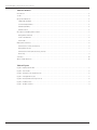
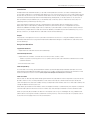
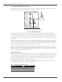
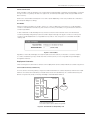
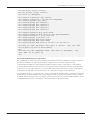
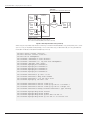
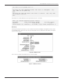
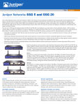
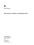
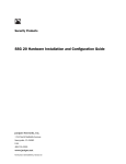
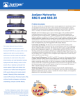
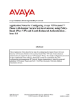
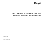
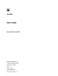
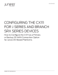
APPLICATION NOTE
CONFIGURING THE CX111
FOR THE SSG SERIES
How to Configure the SSG Series for 3G
Wireless WAN Termination Using the CX111
Cellular Broadband Data Bridge
Copyright © 2010, Juniper Networks, Inc.
1
APPLICATION NOTE - Configuring the CX111 for the SSG Series
Table of Contents
Introduction . . . . . . . . . . . . . . . . . . . . . . . . . . . . . . . . . . . . . . . . . . . . . . . . . . . . . . . . . . . . . . . . . . . . . . . . . . . . . . . . . . . . . . . . . . . . . . . . . . . . . 3
Scope . . . . . . . . . . . . . . . . . . . . . . . . . . . . . . . . . . . . . . . . . . . . . . . . . . . . . . . . . . . . . . . . . . . . . . . . . . . . . . . . . . . . . . . . . . . . . . . . . . . . . . . . . . . 3
Design Considerations. . . . . . . . . . . . . . . . . . . . . . . . . . . . . . . . . . . . . . . . . . . . . . . . . . . . . . . . . . . . . . . . . . . . . . . . . . . . . . . . . . . . . . . . . . . . 3
Supported Hardware. . . . . . . . . . . . . . . . . . . . . . . . . . . . . . . . . . . . . . . . . . . . . . . . . . . . . . . . . . . . . . . . . . . . . . . . . . . . . . . . . . . . . . . . . . . 3
Software Requirements . . . . . . . . . . . . . . . . . . . . . . . . . . . . . . . . . . . . . . . . . . . . . . . . . . . . . . . . . . . . . . . . . . . . . . . . . . . . . . . . . . . . . . . . 3
Card Compatibility . . . . . . . . . . . . . . . . . . . . . . . . . . . . . . . . . . . . . . . . . . . . . . . . . . . . . . . . . . . . . . . . . . . . . . . . . . . . . . . . . . . . . . . . . . . . . 3
Card Activation . . . . . . . . . . . . . . . . . . . . . . . . . . . . . . . . . . . . . . . . . . . . . . . . . . . . . . . . . . . . . . . . . . . . . . . . . . . . . . . . . . . . . . . . . . . . . . . . 3
Description and Deployment Scenario. . . . . . . . . . . . . . . . . . . . . . . . . . . . . . . . . . . . . . . . . . . . . . . . . . . . . . . . . . . . . . . . . . . . . . . . . . . . . 4
Management Interface . . . . . . . . . . . . . . . . . . . . . . . . . . . . . . . . . . . . . . . . . . . . . . . . . . . . . . . . . . . . . . . . . . . . . . . . . . . . . . . . . . . . . . . . . 4
Power over Ethernet. . . . . . . . . . . . . . . . . . . . . . . . . . . . . . . . . . . . . . . . . . . . . . . . . . . . . . . . . . . . . . . . . . . . . . . . . . . . . . . . . . . . . . . . . . . . 5
Dial Modes. . . . . . . . . . . . . . . . . . . . . . . . . . . . . . . . . . . . . . . . . . . . . . . . . . . . . . . . . . . . . . . . . . . . . . . . . . . . . . . . . . . . . . . . . . . . . . . . . . . . . 5
Deployment Scenarios. . . . . . . . . . . . . . . . . . . . . . . . . . . . . . . . . . . . . . . . . . . . . . . . . . . . . . . . . . . . . . . . . . . . . . . . . . . . . . . . . . . . . . . . . . . . 5
CX111 Used for Primary Connectivity . . . . . . . . . . . . . . . . . . . . . . . . . . . . . . . . . . . . . . . . . . . . . . . . . . . . . . . . . . . . . . . . . . . . . . . . . . . . . 5
Management Access . . . . . . . . . . . . . . . . . . . . . . . . . . . . . . . . . . . . . . . . . . . . . . . . . . . . . . . . . . . . . . . . . . . . . . . . . . . . . . . . . . . . . . . . . . . 6
CX111 Used for Backup Access Using Track-ip . . . . . . . . . . . . . . . . . . . . . . . . . . . . . . . . . . . . . . . . . . . . . . . . . . . . . . . . . . . . . . . . . . . . 7
Monitoring. . . . . . . . . . . . . . . . . . . . . . . . . . . . . . . . . . . . . . . . . . . . . . . . . . . . . . . . . . . . . . . . . . . . . . . . . . . . . . . . . . . . . . . . . . . . . . . . . . . . . 9
Summary . . . . . . . . . . . . . . . . . . . . . . . . . . . . . . . . . . . . . . . . . . . . . . . . . . . . . . . . . . . . . . . . . . . . . . . . . . . . . . . . . . . . . . . . . . . . . . . . . . . . . . . 10
About Juniper Networks. . . . . . . . . . . . . . . . . . . . . . . . . . . . . . . . . . . . . . . . . . . . . . . . . . . . . . . . . . . . . . . . . . . . . . . . . . . . . . . . . . . . . . . . . . 10
Table of Figures
Figure 1: Deployment model . . . . . . . . . . . . . . . . . . . . . . . . . . . . . . . . . . . . . . . . . . . . . . . . . . . . . . . . . . . . . . . . . . . . . . . . . . . . . . . . . . . . . . 4
Figure 2: Dial modes. . . . . . . . . . . . . . . . . . . . . . . . . . . . . . . . . . . . . . . . . . . . . . . . . . . . . . . . . . . . . . . . . . . . . . . . . . . . . . . . . . . . . . . . . . . . . . 5
Figure 3: 3G network as the primary link . . . . . . . . . . . . . . . . . . . . . . . . . . . . . . . . . . . . . . . . . . . . . . . . . . . . . . . . . . . . . . . . . . . . . . . . . . . 5
Figure 4: Management access . . . . . . . . . . . . . . . . . . . . . . . . . . . . . . . . . . . . . . . . . . . . . . . . . . . . . . . . . . . . . . . . . . . . . . . . . . . . . . . . . . . . 6
Figure 5: Backup interface using track-ip . . . . . . . . . . . . . . . . . . . . . . . . . . . . . . . . . . . . . . . . . . . . . . . . . . . . . . . . . . . . . . . . . . . . . . . . . . 8
Figure 6: Modem status . . . . . . . . . . . . . . . . . . . . . . . . . . . . . . . . . . . . . . . . . . . . . . . . . . . . . . . . . . . . . . . . . . . . . . . . . . . . . . . . . . . . . . . . . . 9
Figure 7: Modem statistics. . . . . . . . . . . . . . . . . . . . . . . . . . . . . . . . . . . . . . . . . . . . . . . . . . . . . . . . . . . . . . . . . . . . . . . . . . . . . . . . . . . . . . . . 9
2
Copyright © 2010, Juniper Networks, Inc.
APPLICATION NOTE - Configuring the CX111 for the SSG Series
Introduction
Enterprise branches need WAN resiliency to provide uninterrupted service to their customers and employees alike.
This has direct implication to the revenue and operational costs. Financial transactions such as credit card processing,
disaster recovery situations such as wired-line failures due to natural causes, temporary/first day connectivity needs
have necessitated increased up-time with the enterprise HQ (head quarter) or the data center. So far, ISDN, DSL or
dial-up modems have provided majority of the WAN backup connectivity options. These services are usually lowspeed, high latency and have high recurring costs.
Due to their ubiquitous presence, the use of third-generation (3G) wireless networks has become a common
deployment option for both primary and backup connectivity. With the introduction of Juniper Networks® CX111
Cellular Broadband Data Bridge, Juniper offers a simple way to provide wireless connectivity when used as a backup
3G connection (Juniper Networks SSG5 Secure Services Gateway and SSG20 Secure Services Gateway only) or as a
primary connection (all Juniper Networks SSG Series Secure Services Gateways).
Scope
The purpose of this application note is to provide an overview that shows how to configure and deploy the CX111 for
3G wireless WAN termination using the CX111 Cellular Broadband Data Bridge on Juniper Networks SSG Series Secure
Services Gateways.
Design Considerations
Supported Hardware
• Juniper Networks SSG Series Secure Services Gateways
Software Requirements
• Juniper Networks ScreenOS® software versions 5.4.0r16, 6.2.0r6, 6.3.0r3, or later
- - There is a Dynamic Host Configuration Protocol (DHCP) memory leak issue with earlier ScreenOS versions when
used with the CX111
• CX111 firmware 1.6.10 or later
Card Compatibility
As of the date of this writing, about 50 different modems (USB and ExpressCard) have been certified to work with
the CX111 Cellular Broadband Data Bridge. The latest list of modems can be found on the CX111 documentation in the
Technical Publications section for CX111 (www.juniper.net/techpubs/hardware/junos-cx/cx111/).
Card Activation
Before cards can be used, they need to be programmed with the subscriber information required to access the service
provider’s network. This is normally referred to as the card activation process. When the service is purchased, the
carrier will request the card’s ESN number, normally found printed on the wireless card. This is then used to identify the
card by the different activation protocols.
Cards directly purchased from the wireless carrier can ship pre-activated, or sometimes they will ship with a companion
software used to perform the initial activation. In either case, cards already activated do not have to be reactivated.
Cards can optionally be activated from the CX111. This requires users to log into the bridge’s UI using a Web browser
(details about accessing the UI are discussed in the following sections). The activation process only requires users to
access the activation page and click on the activate button.
Copyright © 2010, Juniper Networks, Inc.
3
APPLICATION NOTE - Configuring the CX111 for the SSG Series
Description and Deployment Scenario
The CX111 ships with a default configuration that should accommodate most deployment scenarios. The deployment
model assumes that the CX111 is connected to a DHCP-enabled interface.
192.168.1.0/24
Trust Zone
SSG Series
INTERNET
CX111
OFFICE
Deployment
The CX111 acts as a DHCP server and relays the public
address obtained from the 3G network to the SSG Series.
Figure 1: Deployment model
The CX111 will maintain the wireless modem (or modems, if more than one modem is used) in a disconnected
state, and will trigger a new connection as soon as the SSG Series device requests a new lease and initiates data
transfer. Modem(s) will be disconnected only when no interesting traffic passes through for an idle amount, and only
reconnected when interesting traffic starts again. The idle timeout default is 20mins and can be changed by using the
CX111’s Web UI.
When using the 3G link as the primary connection, long lease times can be used, as generally there won’t be a need to
constantly connect and disconnect the line. On the other hand, if the bridge is used to provide a backup connection,
short lease times (in the order of a minute) are commonly used, so when the primary link is active, the backup link can
be disabled, triggering a disconnection, in the worse case, after a lease time.
The CX111 assigns the address received from the wireless service provider to the gateway (normally this is a public
address). For obvious reasons, only a single device can be connected to the CX111 at any given time, or else multiple
devices will contend for the only address passed to the CX111. The CX111 works in “pass through” mode, simply relaying
all traffic from the wireless network to the DHCP client.
Management Interface
The CX111 provides a Web-based management interface, and it can be accessed even when 3G modems are not used.
Since “pass through” mode is used (instead of a routed connection, with the bridge doing Network Address Translation
(NAT)), the management interface cannot be accessed through the normal data channel. When the modem is not
active or not inserted, a 192.168.30.x/24 network address is provided to the SSG Series platform and 192.168.30.1
becomes the temporary management address for the CX111.
The management interface is still accessible through the Ethernet port, but VLAN tagging is used to separate
management form data traffic using the following parameters
Table 1: Management Network Settings
4
CARD MODEL
WIRELESS TECHNOLOGY
Management subnet
192.168.0.0/24
Management address
192.168.0.1
VLAN ID
3900
Copyright © 2010, Juniper Networks, Inc.
APPLICATION NOTE - Configuring the CX111 for the SSG Series
Power over Ethernet
When available, Power over Ethernet (PoE) can be used to power the bridge. In the event that the bridge is connected
through a switch or a gateway that does not support PoE, an external power supply can be used (provided with the
basic install kit).
When PoE is used, the device will require 4 W to 10 W of power depending on how many modems are connected, so
plan the power budget accordingly.
Dial Modes
The CX111 can be configured in two modes, “always on” or “dial on-demand.” In the “always on” mode, the bridge
connects to the 3G network after booting. The connection is always maintained, as long as there are no network or
connectivity problems.
In “dial on-demand” mode, the bridge will only initiate a connection when it receives traffic from the interface
connecting the bridge and gateway. In particular, DHCP request messages will trigger a connection. Similarly, the
connection will be dropped after a configurable inactivity timeout. The configuration is found under the Modem>Settings tab.
Figure 2: Dial modes
Regardless of the mode, the bridge can accept multiple cards simultaneously. In the event of a failure or inability
to connect, the remaining card(s) will be used. The connection priority is user configurable through the bridge’s
management interface.
Deployment Scenarios
In the following section, we will discuss several common deployment scenarios and provide the associated configurations.
CX111 Used for Primary Connectivity
This first scenario shows the gateway configuration when the 3G network is used as the primary WAN link. On Juniper
Networks SRX Series Services Gateways and SSG Series Secure Services Gateways, this can be achieved using the
default configuration by simply connecting the bridge to the ethernet0/0 interface.
192.168.1.0/24
Trust Zone
INTERNET
SSG Series
CX111
OFFICE
Primary Access
CX111 used as the primary link.
The SSG Series obtains a public address through DHCP.
Figure 3: 3G network as the primary link
Copyright © 2010, Juniper Networks, Inc.
5
APPLICATION NOTE - Configuring the CX111 for the SSG Series
set
set
set
set
set
set
set
set
set
set
set
set
zone “Trust” vrouter “trust-vr”
zone “Untrust” vrouter “trust-vr”
interface “ethernet0/0” zone “Untrust”
interface “bgroup0” zone “Trust”
interface bgroup0 port ethernet0/2
interface bgroup0 port ethernet0/3
interface bgroup0 port ethernet0/4
interface bgroup0 port ethernet0/5
interface bgroup0 port ethernet0/6
interface ethernet0/0 dhcp client enable
interface ethernet0/0 dhcp client settings update-dhcpserver
interface bgroup0 ip 192.168.1.1/24
set interface bgroup0 dhcp server service
set interface bgroup0 dhcp server enable
set interface bgroup0 dhcp server ip 192.168.1.2 to 192.168.1.100
set policy id 3 name “Any Permit” from “Trust” to “Untrust”
nat src permit log count
exit
“Any” “Any” “ANY”
Management Access
A VLAN-tagged logical interface can be used in order to provide access to the bridge’s management console. NAT will
also be used to facilitate access from any device behind the gateway, eliminating the need for complex routing (as all
traffic to the bridge’s management interface will be translated as if it originated from the management subnet).
VLAN Data
No tagging used for data traffic DHCP assigned
address (relayed from the 3G network)
192.168.1.0/24
Trust Zone
DHCP Client
Untrust Zone
e0/0
SSG Series
CX111
192.168.0.1/24
Management
Zone
OFFICE
VLAN Management
VLAN Tag 3900
Figure 4: Management access
6
Copyright © 2010, Juniper Networks, Inc.
APPLICATION NOTE - Configuring the CX111 for the SSG Series
set zone “Trust” vrouter “trust-vr”
set zone “Untrust” vrouter “trust-vr”
set zone id 100 “Management”
set
set
set
set
set
set
set
set
interface
interface
interface
interface
interface
interface
interface
interface
“ethernet0/0” zone “Untrust”
“ethernet0/0.1” tag 3900 zone “Management”
“bgroup0” zone “Trust”
bgroup0 port ethernet0/2
bgroup0 port ethernet0/3
bgroup0 port ethernet0/4
bgroup0 port ethernet0/5
bgroup0 port ethernet0/6
set
set
set
set
set
set
set
interface
interface
interface
interface
interface
interface
interface
ethernet0/0 dhcp client enable
ethernet0/0 dhcp client settings update-dhcpserver
ethernet0/0.1 ip 192.168.0.2/24
bgroup0 ip 192.168.1.1/24
bgroup0 dhcp server service
bgroup0 dhcp server enable
bgroup0 dhcp server ip 192.168.1.2 to 192.168.1.20
set policy id 3 name “Any Permit” from “Trust” to “Untrust” “Any” “Any” “ANY”
nat src permit log count no-session-backup
exit
set policy id 6 name “Management Access” from “Trust” to “Management” “Any”
“Any” “HTTP” nat src permit log
exit
CX111 Used for Backup Access Using Track-ip
Only Juniper Networks SSG5 Secure Services Gateway and SSG20 Secure Services Gateway can support the CX111 as
both backup and primary. All other SSG Series devices support CX111 only in primary connection mode.
In this example, the bridge will only be used when the primary interface is down. It is possible to configure default
routes with different metrics, but this will mean that only physical failures in the primary interface will be detected. In
some instances, such as when layer 2 protocols are not able to detect end-to-end failures, or when multiple network
hops separate the SSG Series from the remote resources, other means to trigger a failover are desired.
This example shows how to configure track-ip to monitor a set of devices. Different weights can be used to change the
failover behavior. When each probe is given a weight higher than 255, a single failure will trigger a failover. If instead
multiple probes are used, each with a small weight (lower than 255), more than one failure will be required to fail over.
To enable the backup, the sum of the weights of the failing probes must be larger than 255.
Copyright © 2010, Juniper Networks, Inc.
7
APPLICATION NOTE - Configuring the CX111 for the SSG Series
TRACK-IP
Monitored server used to test the primary link
192.168.1.0/24
Trust Zone
SSG Series
e0/1
e0/0
INTERNET
198.0.0.1
CX111
OFFICE
Backup Scenario
e0/0 is used as the primary link (static public IP).
e0/1 connects to the CX111 (DHCP) and is used as a backup.
Figure 5: Backup interface using track-ip
When using track-ip, the backup interface connecting to the CX111 will be disabled as long as the primary link is active
(that is, as long as the probes are responding). This is useful when using on-demand mode, as it will guarantee that
the modem will be disconnected while the primary link is up.
8
set
set
set
set
set
set
set
set
set
set
set
set
zone “Trust” vrouter “trust-vr”
zone “Untrust” vrouter “trust-vr”
zone id 100 “Management”
interface “ethernet0/0” zone “Untrust”
interface “ethernet0/1” zone “Untrust”
interface “ethernet0/1.1” tag 3900 zone “Management”
interface “bgroup0” zone “Trust”
interface bgroup0 port ethernet0/2
interface bgroup0 port ethernet0/3
interface bgroup0 port ethernet0/4
interface bgroup0 port ethernet0/5
interface bgroup0 port ethernet0/6
set
set
set
set
interface
interface
interface
interface
ethernet0/0 ip 198.1.1.1/24
ethernet0/1 dhcp client enable
ethernet0/1.1 ip 192.168.0.10/24
bgroup0 ip 192.168.1.1/24
set
set
set
set
interface
interface
interface
interface
ethernet0/0
ethernet0/0
ethernet0/0
ethernet0/0
set
set
set
set
interface
interface
interface
interface
bgroup0
bgroup0
bgroup0
bgroup0
dhcp
dhcp
dhcp
dhcp
monitor track-ip
monitor track-ip
monitor track-ip
backup interface
server
server
server
server
ip
ip 198.0.0.1 interval 5
ip 198.0.0.1 weight 255
ethernet0/1 type track-ip
service
enable
option dns1 192.168.1.1
ip 192.168.1.2 to 192.168.1.20
Copyright © 2010, Juniper Networks, Inc.
APPLICATION NOTE - Configuring the CX111 for the SSG Series
set route 0.0.0.0/0 gateway 198.1.1.2
set policy id 6 name “Management Access” from “Trust” to “Management” “Any”
“Any” “HTTP” nat src permit log
exit
set policy id 3 name “Any Permit” from “Trust” to “Untrust” “Any” “Any” “ANY”
nat src permit log count
exit
The probe status can be obtained from the “get interface monitor” command.
SSG5-> get interface ethernet0/0 monitor track-ip
ip address
intval threshold wei gateway
fail-count success
198.0.0.1
5
3 255 0.0.0.0
0 74%
failure weight: 255, threshold: 1, not failed: 0 ip(s) failed, weighted sum = 0
Monitoring
The 3G signal strength and connection status can be monitored from the bridge’s management interface, which
is found under status -> device info tab. The signal strength bars are only displayed for 3G modems that support
Dynamic Signal Strength.
Figure 6: Modem status
Traffic statistics can be found under the Status->Statistics page.
Figure 7: Modem statistics
Copyright © 2010, Juniper Networks, Inc.
9
APPLICATION NOTE - Configuring the CX111 for the SSG Series
Summary
As more and more wireless carriers expand their coverage and upgrade their networks to offer 3G wireless data
services, enterprises worldwide can look to use 3G as a backup connectivity solution for many deployments and in
some cases, even use 3G wireless as primary data access.
Juniper Networks SSG Series Secure Services Gateways provide best-in-class security and routing with flexible LAN
and WAN options. With the CX111 Cellular Broadband Data Bridge, the SSG Series offers wireless WAN connectivity
solutions with increased uptime and reduced operating cost. The CX111 combined with the SSG Series is simple and
easy to configure and deploy.
About Juniper Networks
Juniper Networks, Inc. is the leader in high-performance networking. Juniper offers a high-performance network
infrastructure that creates a responsive and trusted environment for accelerating the deployment of services and
applications over a single network. This fuels high-performance businesses. Additional information can be found at
www.juniper.net.
Corporate and Sales Headquarters
APAC Headquarters
EMEA Headquarters
To purchase Juniper Networks solutions,
Juniper Networks, Inc.
Juniper Networks (Hong Kong)
Juniper Networks Ireland
please contact your Juniper Networks
1194 North Mathilda Avenue
26/F, Cityplaza One
Airside Business Park
Sunnyvale, CA 94089 USA
1111 King’s Road
Swords, County Dublin, Ireland
representative at 1-866-298-6428 or
Phone: 888.JUNIPER (888.586.4737)
Taikoo Shing, Hong Kong
Phone: 35.31.8903.600
or 408.745.2000
Phone: 852.2332.3636
EMEA Sales: 00800.4586.4737
Fax: 408.745.2100
Fax: 852.2574.7803
Fax: 35.31.8903.601
authorized reseller.
www.juniper.net
Copyright 2009 Juniper Networks, Inc. All rights reserved. Juniper Networks, the Juniper Networks logo, Junos,
NetScreen, and ScreenOS are registered trademarks of Juniper Networks, Inc. in the United States and other
countries. All other trademarks, service marks, registered marks, or registered service marks are the property of
their respective owners. Juniper Networks assumes no responsibility for any inaccuracies in this document. Juniper
Networks reserves the right to change, modify, transfer, or otherwise revise this publication without notice.
3500185-001-EN
10
Mar 2010
Printed on recycled paper
Copyright © 2010, Juniper Networks, Inc.