1
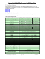
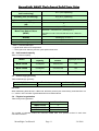
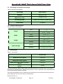
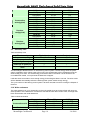
NAND Flash-based Solid State Drive
Standard Type GT series
Product Specification
Version 1.0
Oct. 2008
INFORMATION IN THIS DOCUMENT IS PROVIDED IN RELATION TO MEMORIGHT
PRODUCTS, AND IS SUBJECT TO CHANGE WITHOUT NOTICE.
NOTHING IN THIS DOCUMENT SHALL BE CONSTRUED AS GRANTING ANY LICENSE,
EXPRESS OR IMPLIED, BY ESTOPPEL OR OTHERWISE, TO ANY INTELLECTUAL
PROPERTY RIGHTS IN MEMORIGHT PRODUCTS OR TECHNOLOGY.
ALL INFORMATION IN THIS DOCUMENT IS PROVIDED ON AS "AS IS" BASIS WITHOUT
GUARANTEE OR WARRANTY OF ANY KIND.
1. For updates or additional information about MemoRight products, contact your nearest
MemoRight office.
2. MemoRight products are not intended for use in life support, critical care, medical, safety
equipment, or similar applications where products failure could result in loss of life or personal
or physical harm, or any military or defense application, or any governmental procurement to
which special terms or provisions may apply.
* MemoRight reserves the right to change products or specification without notice.
Copyright Notice:
Copyright © 2008 by MemoRight Memoritech(Shenzhen)Co., LTD. All rights reserved.
Information contained in this document, including but not limited to any instructions, descriptions
and product specifications, is proprietary to MemoRight Inc. and shall not be modified, used,
copied, reproduced or disclosed in whole or in part, in any form or by any means, electronic or
mechanical, for any purpose, without the written consent of MemoRight Memoritech(Shenzhen)
Co., LTD.
Revision History
Revision
No
0.0
0.1
1.0
History
Draft Date
Remark
Initial issue
Performance data updated
Performance update
Mar. 14,2008
Sept. 9, 2008
Oct. 20, 2008
Preliminary
Preliminary
Formal
The attached data sheets are prepared and approved by MemoRight. And MemoRight has the
right to change all the specifications in data sheets. MemoRight will evaluate and reply to any
dear customer‘s requests and questions on the parameters of this device. If dear customer has
any questions, please call or fax to MemoRight headquarters, or contact the MemoRight
branch office near your office.
MemoRight NAND Flash-based Solid State Drive
Contents
1.
GENERAL DESCRIPTION ........................................................................................................................ 7
1.1
DENSITY ................................................................................................................................................. 7
1.2
FORM FACTOR ....................................................................................................................................... 7
1.3
HOST INTERFACE ................................................................................................................................... 7
1.4
PERFORMANCE ...................................................................................................................................... 7
1.5
RELIABILITY ............................................................................................................................................ 7
1.5.1
Wear Leveling.............................................................................................................................. 7
1.5.2
Endurance.................................................................................................................................... 7
1.5.3
ECC............................................................................................................................................... 7
1.5.4
Bad block management algorithm............................................................................................ 7
1.5.5
MTBF(Mean Time between Failures) ...................................................................................... 7
1.5.6
Data Retention ............................................................................................................................ 8
1.6
POWER CONSUMPTION .......................................................................................................................... 8
1.7
ENVIRONMENTAL ................................................................................................................................... 8
1.7.1
Temperature ................................................................................................................................ 8
1.7.2
Shock............................................................................................................................................ 8
1.7.3
Vibration ....................................................................................................................................... 8
1.8
NSSD FUNCTIONAL BLOCK DIAGRAM .................................................................................................. 8
2
PHYSICAL SPECIFICATIONS.................................................................................................................. 9
3
DRIVE SPECIFICATIONS ....................................................................................................................... 10
3.1
SPECIFICATION SUMMARY TABLE ........................................................................................................ 10
3.2
UNFORMATTED CAPACITY.................................................................................................................... 11
3.3
DEFAULT LOGIC GEOMETRY ................................................................................................................ 11
3.4
PHYSICAL ORGANIZATION .................................................................................................................... 11
3.5
RECORDING AND INTERFACE TECHNOLOGY ........................................................................................ 12
3.6
PHYSICAL CHARACTERISTICS .............................................................................................................. 12
3.7
ACCESS TIME ....................................................................................................................................... 12
3.8
PERFORMANCE CHARACTERISTICS ..................................................................................................... 13
3.9
START/STOP TIME ................................................................................................................................ 14
3.10 WRITE ENDURANCE ............................................................................................................................. 14
3.11 POWER SPECIFICATIONS ..................................................................................................................... 15
3.11.1 Power consumption .................................................................................................................. 15
3.11.2 Conducted Noise ...................................................................................................................... 15
3.11.3 Voltage tolerance ...................................................................................................................... 16
3.12 ENVIRONMENTAL SPECIFICATIONS ...................................................................................................... 16
3.12.1 Ambient temperature................................................................................................................ 16
3.12.2 Acoustics .................................................................................................................................... 16
3.12.3 Electromagnetic immunity........................................................................................................ 16
3.12.4 Gravitation.................................................................................................................................. 16
3.12.5 Medium....................................................................................................................................... 16
3.13 RELIABILITY .......................................................................................................................................... 16
3.14 AGENCY CERTIFICATION ...................................................................................................................... 16
3.15 ENVIRONMENTAL PROTECTION ............................................................................................................ 16
4
CONFIGURING AND MOUNTING THE DRIVE ................................................................................... 17
4.1
4.2
4.3
5
STATIC DISCHARGE AND HANDLING PRECAUTIONS ............................................................................. 17
DRIVE MOUNTING ................................................................................................................................. 17
INSTALLATION CONSIDERATIONS ......................................................................................................... 17
SATA INTERFACE.................................................................................................................................... 19
5.1
SATA INTERFACE SIGNALS AND CONNECTOR PINS ............................................................................ 19
5.1.1
Signal Segment Pin-out Configuration................................................................................... 19
5.1.2
Power Segment Pin-out Configuration .................................................................................. 19
5.2
SUPPORTED ATA COMMANDS ............................................................................................................. 20
5.2.1
Recalibrate (10h) ...................................................................................................................... 21
MemoRight Confidential
Page 3
3/6/2009
MemoRight NAND Flash-based Solid State Drive
5.2.2
5.2.3
5.2.4
5.2.5
5.2.6
5.2.7
5.2.8
5.2.9
5.2.10
5.2.11
5.2.12
5.2.13
5.2.14
5.2.15
5.2.16
5.2.17
5.2.18
5.2.19
5.2.20
5.2.21
5.2.22
5.2.23
5.2.24
5.2.25
5.2.26
5.2.27
5.2.28
5.2.29
5.2.30
5.2.31
5.2.32
5.2.33
6
Read Sector(s) (20h)................................................................................................................ 21
Read Sector(s) EXT (24h) ....................................................................................................... 21
Read DMA EXT(25h) ............................................................................................................... 21
Read Multiple EXT(29h)........................................................................................................... 21
Write Sector(s) (30h) ................................................................................................................ 21
Write Sector(s) EXT(34h) ........................................................................................................ 21
Write DMA EXT(35h)................................................................................................................ 21
Write Multiple EXT(39h)........................................................................................................... 21
Read/Verify Sector(s) (40h)..................................................................................................... 21
Read Verify Sector(s) EXT(42h) ............................................................................................. 22
Seek (70h).................................................................................................................................. 22
Execute Device Diagnostic (90h) ........................................................................................... 22
Initialize Device Parameters (91h) ......................................................................................... 22
S.M.A.R.T (B0h)........................................................................................................................ 22
Read Multiple (C4h).................................................................................................................. 22
Write Multiple (C5h).................................................................................................................. 22
Set Multiple Mode (C6h) .......................................................................................................... 22
Read DMA (C8h)....................................................................................................................... 22
Write DMA (CAh) ...................................................................................................................... 22
Standby Immediate (E0h) ........................................................................................................ 22
Idle immediate (E1h or 95h) .................................................................................................... 22
Standby (E2h)............................................................................................................................ 22
Idle (E3h).................................................................................................................................... 23
Read Buffer (E4h) ..................................................................................................................... 23
Check Power (E5h or 98h) ...................................................................................................... 23
Sleep (E6h) ................................................................................................................................ 23
Flush Cache (E7h).................................................................................................................... 23
Write Buffer (E8h) ..................................................................................................................... 23
Flush CACHE EXT(EAh) ......................................................................................................... 23
Identity Device (ECh) ............................................................................................................... 23
Set Features (EFh) ................................................................................................................... 26
Set Features command............................................................................................................ 26
COMPATIBILITY SUMMARY .................................................................................................................. 28
6.1
TESTED HARDWARE PLATFORM VERSIONS ......................................................................................... 28
6.1.1
Desktop platform ....................................................................................................................... 28
6.1.2
Notebook platform..................................................................................................................... 29
6.1.3
RAID platform ............................................................................................................................ 29
6.2
TESTED OPERATING SYSTEM VERSIONS ............................................................................................. 29
7
COMPLIANCE ........................................................................................................................................... 29
ROHS .............................................................................................................................................................. 30
FCC.................................................................................................................................................................. 32
CE .................................................................................................................................................................... 33
MTBF ............................................................................................................................................................... 34
8
ORDERING INFORMATION ................................................................................................................... 36
9
MEMORIGHT SUPPORT SERVICES ................................................................................................... 37
PRODUCT QUALITY ASSURANCE ..................................................................................................................... 37
AFTER SERVICE ................................................................................................................................................ 37
CONTACT INFORMATION ................................................................................................................................... 37
MemoRight Confidential
Page 4
3/6/2009
MemoRight NAND Flash-based Solid State Drive
List of Tables
Table 1.Specification Summary
Table 2.Products capacity
Table 3.Default logic geometry
Table 4.Physical organization
Table 5.Recording and interface technology
Table 6.Physical characteristics
Table 7.Access time
Table 8.Performance characteristics
Table 9.Start/stop time
Table 10.Write endurance
Table 11.Power Consumption
Table 12.Ambient temperature
Table 13.SATA Connector Signal Definitions
Table 14.SATA Connector Power segment Definitions
Table 15.Supported ATA commands
Table 16.Drive-specific features
Table 17.Set features description
Table 18.Tested PC platform Mother Board versions
Table 19.Tested Notebook platform Mother Board versions
Table 20.Tested RAID platform
Table 21.Tested Operating system versions
Table 22.Contact information
MemoRight Confidential
Page 5
3/6/2009
MemoRight NAND Flash-based Solid State Drive
List of Figures
Figure 1.NSSD Functional Block Diagram
Figure 2.Physical specifications
Figure 3.Memoright SATA Connector View
Figure 4.Ordering Information
MemoRight Confidential
Page 6
3/6/2009
MemoRight NAND Flash-based Solid State Drive
1. General Description
The NSSD (NAND Flash-based Solid State Drives) of MemoRight consists of semiconductor devices
completely, and the storage media is NAND Flash which has high reliability and high compatibility.
As the NSSD doesn't have any mechanical part such as platter (disk), motor and suspension, it gives a
good solution in a UMPC and Tablet PC for a storage device with high performance and low power
consumption and small form factor.
At the same time it gives rugged feature in industrial PC with an extreme environment and an
increased MTBF.
For an easy adoption, the NSSD has the same device interface and physical dimension with HDD.
1.1 Density
32GBytes, 64GBytes, 128GBytes
1.2 Form Factor
2.5" Type (100.20 x 69.85 x 9.50)mm
1.3 Host interface
PIO Mode 0 to 4
UDMA Mode 0 to 6
Serial ATA 1.0a specification
1.4 Performance
Host Interface: Max 150MB/s
Sustained Read transfer: Max 120MB/s (100MB/s for 128GB)
Sustained Write transfer: Max 120MB/s (100MB/s for 128GB)
Access time: < 0.1ms
Random IOPS Read @512Bytes: 10,000(9600 for 128GB)
Random IOPS Write@512Bytes: 600(500 for 128GB )
1.5 Reliability
1.5.1
Wear Leveling
This drive uses dynamic, static and active (initiative) balanced wear leveling strategy, which will ensure
that all blocks have nearly same wear level, and reduce the dependence of the write endurance on
access pattern.
1.5.2
Endurance
Write endurance: >10 years @ 1TByte/day (64GB type)
Read endurance: unlimited
1.5.3
ECC
This drive also implements an enhanced ECC algorithm, which reduces the error rate and enforces
the write endurance at same time. 4-bit error correction per sector(512 Bytes).
1.5.4
Bad block management algorithm
This drive has a certain number of reserved blocks. When a user data block fails, a reserved block will
replace the failed block. The replacement of bad block is transparent to user.
1.5.5
MTBF(Mean Time between Failures)
More than 1,100,000 hours ( 32GB typical )
Calculation model: Telcordia SR-332 Issue 1 Method 1, Case 1
MemoRight Confidential
Page 7
3/6/2009
MemoRight NAND Flash-based Solid State Drive
1.5.6
Data Retention
Data retention :>10 years
Test under room temperature.
1.6
Power consumption
Input voltage: +5VDC, ±5%(4.75V ~ 5.25V)
Continue write : Typical 400mA
Continue read : Typical 400mA
Idle : Typical 200mA
Standby : Typical 200mA
Test under room temperature @ 5V
1.7
Environmental
1.7.1
Temperature
Operating : 0'C ~ 70'C(Commercial)
Non-Operation: -40'C ~ 85'C
1.7.2
Shock
Operating: 50G, duration 11ms, Half Sine Wave
Non-Operating: 1500G, duration 0.5ms, Half Sine Wave
1.7.3
Vibration
Operating: 16.4G Peak, 10~2000Hz, x3 Axis
1.8
NSSD Functional Block Diagram
Figure 1.NSSD Functional Block Diagram
MemoRight Confidential
Page 8
3/6/2009
MemoRight NAND Flash-based Solid State Drive
2 Physical specifications
Figure 2.Physical specifications
MemoRight Confidential
Page 9
3/6/2009
MemoRight NAND Flash-based Solid State Drive
3 Drive Specifications
Unless otherwise noted, all specifications are measured under ambient conditions, at 25°C, and
nominal power. For convenience, the phrases of the drives used throughout this manual are indicated
the following drive models:
MR25.2-032S
MR25.2-064S
MR25.2-128S
3.1
Specification Summary table
The specifications listed in the table below are for quick reference. For details on specification
measurement or definition, see the appropriate section of this manual.
Table 1: Specifications Summary
Drive specification
Unformatted capacity
Guaranteed sectors
Sustained data transfer
rate(read)
Sustained data transfer
rate(write)
Channels
Media type
Random 512Byte IOPS(read)
Random 512Byte IOPS(write)
Interface
I/O data-transfer rate
ATA data-transfer modes
supported
Cache buffer
Height
width
Length
Weight(grams)
Average latency(Typical)
Power-on to ready(Typical)
Standby to ready(Typical)
Warm-up current (Typical)* *
Continue read power(Typical) * *
Continue write power (Typical)* *
Idle mode power(Typical) * *
Standby mode power(Typical) * *
Sleep mode power(Typical)* *
Voltage tolerance (including
noise)
MR25.2-032S
32GB *
62,914,560
MR25.2-064S
64GB *
125,829,120
MR25.2-128S
128GB *
251,658,240
120 Mbytes/sec
120 Mbytes/sec
100 Mbytes/sec
120 Mbytes/sec
120 Mbytes/sec
100 Mbytes/sec
4
Single Layer Cell (SLC) NAND Flash
10,000
10,000
9600
600
600
500
Serial ATA 1.0a
150 Mbytes/sec
PIO modes 0-4, Ultra DMA modes 0-6
32 Mbytes
0
0
9.5 -0.1 mm (0.374 -0.004 inches)
0
0
69.85 -0.1 mm (2.75
-0.004 inches)
0
0
100.5 -0.1 mm (3.96
-0.004 inches)
78.0±5.0
<0.1 msec
1 sec
0.1 sec
0.75 amps
2.0 watts
2.0 watts
1 watts
1 watts
1 watts
5V ± 5%
0° to 70°C (operating)
–40° to 85°C (non-operating)
20°C (operating)
Ambient temperature
Temperature gradient
MemoRight Confidential
88.0±5.0
Page 10
3/6/2009
MemoRight NAND Flash-based Solid State Drive
(°C per hour max,
non-condensing)
30°C (non-operating)
Humidity (non-condensing)
50%,95% (operating)
Relative humidity gradient
Drive acoustics, sound power
(dB)
Non-recoverable read errors
30% per hour max
Mean Time Before Failure
(MTBF)
0
< 1 per 1014 bits read
More than 1,100,000 hours ( 32GB typical )
Calculation model: Telcordia SR-332 Issue 1 Method 1,
Case 1
Altitude
0-80000(Ft) / 0-24(km.)
Service life
Warranty* * *
5 Years
5 Years
* 1GB = 1,000,000,000 Bytes
* * typical value under room temperature
* * * three-years free warranty and two-years paid maintenance.
3.2
Unformatted capacity
Table 2: Products capacity
3.3
Model
Unformatted
capacity
Guaranteed
sectors
Bytes per sector
MR25.2-032S
32 GBytes
62,914,560
512
MR25.2-064S
64 GBytes
125,829,120
512
MR25.2-128S
128 GBytes
251,658,240
512
Default logic geometry
Table 3:Default logic geometry
Cylinders
16383
Read/write heads
16
Sectors per track
63
LBA mode
When addressing these drives in LBA mode, all blocks (sectors) are consecutively numbered from 0 to
n–1, where n is the number of guaranteed sectors as defined above.
3.4
Physical organization
Table 4:Physical organization
Model
MR25.2-032S
MR25.2-064S
MR25.2-128S
Channels
4
4
4
The number of channels means the maximum NAND flash units parallel involved in each host
command execution.
MemoRight Confidential
Page 11
3/6/2009
MemoRight NAND Flash-based Solid State Drive
3.5
Recording and interface technology
Table 5: Recording and interface
3.6
Technology
Specification
Interface
Serial ATA 1.0a
Interface data transfer rate
(Mbytes/sec max)
150(SATA 1.0a)
Recording media
Single Layer Cell(SLC) NAND flash
Cache buffer
32 Mbytes
Physical characteristics
Table 6: Physical characteristics
(mm)
Height
(inches)
(mm)
Width
(inches)
(mm)
Length
(inches)
(grams)
Typical weigtht
(pounds)
3.7
0
9.5 -0.1
0
0.374
-0.004
0
69.85 -0.1
0
2.75 -0.004
0
100.5 -0.1
0
3.96 -0.004
78.0±5.0(32G & 64G)
/88.0±5.0(128G)
0.172±0.011(32G & 64G)
/0.194±0.011(128G)
Access time
Table 7:Access time
Access time
Read(cache hit), typical
0.04 msec
Read(cache miss), typical
0.08 msec
Write(cache hit or cache non-full),
typical
Write(cache miss and cache full),
typical
0.04 msec
2 msec
The time accessing to data in HDD equals to that the seek time plus the latency time, not including
controller time overhead. But for SSD, the latency time is 0, and the seek time is very small. Most of the
time is consumed by controller overhead.
The access time definition here is measured from the last byte of host command received by drive to
the first data byte sent to host by drive in read operation.
Notes for Section 3.7
MemoRight Confidential
Page 12
3/6/2009
MemoRight NAND Flash-based Solid State Drive
*Assumes that no error and no sector is relocated.
* *Assumes that system ability supports the UDMA-6.
3.8
Performance characteristics
The performance test results are based on environments as below:
Mother Board:
CPU:
Chipset:
Graphic:
RAM:
BIOS:
OS:
Test software:
SSD:
GIGBYTE X38-DQ6
E8400 3.00GHz
Intel X38 + ICH9R
NVIDIA6200LE
Kingston 2GB DUAL channel DDR2-800
Award/6.00PG/F7
Windows XP pro sp2
IOMeter 2006.07.27
MR25.2-032S (FW: B8J22D1F)
/MR25.2-064S(FW: B8J22D1F)
/MR25.2-128S (FW: B8J22D4F)
Five minutes
Test sustaining time:
Table 8:Performance characteristics
SSD
Test item
MR25.2-032S/ MR25.2-064S
Request size
0.5KBytes
4 KBytes
8 KBytes
64KBytes
128 KBytes
0.5KBytes
4 KBytes
8 KBytes
64KBytes
128 KBytes
0.5KBytes
4 KBytes
8 KBytes
64KBytes
128 KBytes
0.5KBytes
4 KBytes
8 KBytes
64KBytes
128 KBytes
Consecutive
read(typical)
Consecutive
write(typical)
Random
read(typical)
Random
write(typical)
Throughput(MByte
s/sec)
8.76
37.88
51.21
112.79
118.05
9.14
54.87
78.42
122.81
126.53
5.11
23.62
37.81
96.27
108.33
0.32
1.42
1.89
10.32
19.34
SSD
IOPS
17,941
9,697
6,555
1,805
944
18,724
14,047
10,037
1,965
1,012
10,475
6,046
4,839
1,540
867
650
364
242
165
155
MR25.2-128S
Test item
Request size
Consecutive
read(typical)
0.5KBytes
4 KBytes
MemoRight Confidential
Throughput(MByte
s/sec)
8.21
34.29
Page 13
IOPS
16,816
8,779
3/6/2009
MemoRight NAND Flash-based Solid State Drive
8 KBytes
64KBytes
128 KBytes
0.5KBytes
4 KBytes
8 KBytes
64KBytes
128 KBytes
0.5KBytes
4 KBytes
8 KBytes
64KBytes
128 KBytes
0.5KBytes
4 KBytes
8 KBytes
64KBytes
128 KBytes
Consecutive
write(typical)
Random
read(typical)
Random
write(typical)
3.9
45.97
97.19
101.34
8.42
52.09
75.35
104.04
104.01
4.72
20.80
33.10
83.73
93.40
0.30
1.33
1.78
9.77
17.60
5,884
1,555
811
17,238
13,336
9,645
1,665
832
9,675
5,325
4,236
1,340
747
605
341
228
156
141
Start/stop time
Table 9:Start/stop time
Time to ready
Power-on to ready
Warm-up time
Standby to ready
Power-off to power-on
Power-off to cache flush
done
Typical(sec)
1
5
0.1
1
Max(sec)
10
10
0.1
/
0.1
1
The MemoRight’s NSSD have an on-drive backup power system. It saves energy when the power
supply is applied to drive. When power-off occurring, the saved energy will be released to keep the
drive working for a while. The saved energy ensures the data in the cache can be flushed to the
nonvolatile flash media, which prevents the data loss to happen.
It will take about 5 seconds to save enough energy for discharge at lease 1 second. The write cache
will be disabled automatically before the backup power system saved enough energy.
The cycle number of the backup power system is at lease 300,000 to ensure covering the lifespan of
the drive.
3.10 Write endurance
The write endurance is mostly depending on the write model since each write to flash will cause an
erase operation of the data block. Consecutive write will be better than random write, and large date
block will be better than small data block.
Table 10:Write endurance
Consecutive write
Random
Request size
2 KBytes
16 KBytes
128 KBytes
2 KBytes
MemoRight Confidential
TBytes/GBytes
>100
>100
>100
>1.6
Page 14
IO/GBytes
>5×10¹⁰
>6.3×10⁹
>7.8×10⁸
>8×10⁸
3/6/2009
MemoRight NAND Flash-based Solid State Drive
write(100% cache
miss)
16 KBytes
128 KBytes
>3.2
>25
>2×10⁸
>2×10⁸
In actual application environments, since this drive have a 32MByte cache and the cache strategy fine
tuned for NAND flash, the write endurance will exceed this specification in almost all situation.
3.11 Power specifications
The drive receives DC power (+5V) through the interface connector.
3.11.1 Power consumption
Power requirement for the drive is listed in the table. Typical power measurements are based on an
average of drive testing, under nominal conditions, using 5.0V input voltage at room temperature.
z
Warm-up power
Warm-up power is measured from the time of power-on to the time that the drive’s back up power
system has stored enough energy.
z
Read power
The read power is measured with three 63 sectors read operations every 100msecs.
The consecutive read power is measured with consecutive 128Kbytes read operations.
z
Write power
The write power is measured with three 63 sectors write operations every 100msecs.
The consecutive write power is measured with consecutive 128Kbytes write operations.
z
Idle mode power
The idle power is measured with no read/wrote operation.
z
Standby mode power
During Standby mode, the drive accepts commands, and the DRAM cache is in sleep mode and the
MCU is running in slower clock.
Table 11:Power Consumption
Power mode
Warm-up
Read
Consecutive read
Write
Consecutive write
Idle
Standby
Power consumption(watts) (+5V, Room
Temp)
3.75
1.0
2.0
1.0
2.0
1.0
1.0
3.11.2 Conducted Noise
Input noise ripple is measured at the host system power supply across an equivalent 25-ohm resistive
loading on the +5 volt line.
Using 5-volt power, the drive is expected to operate with a maximum of 100 mV peak-to-peak
square-wave injected noise at up to 10 MHz.
Note: Equivalent resistance is calculated by dividing the nominal voltage by the typical RMS read/write
current.
MemoRight Confidential
Page 15
3/6/2009
MemoRight NAND Flash-based Solid State Drive
3.11.3 Voltage tolerance
Voltage tolerance (including noise):
5V ± 5%
3.12 Environmental specifications
3.12.1 Ambient temperature
Ambient temperature is defined as the temperature of the environment immediately surrounding the
drive. Actual drives usual temperature should not exceed 70°C (158°F) within the operating ambient
conditions.
Above 1,000 feet (305 meters), the maximum temperature is decreased linearly by 1°C every 1000
feet.
Table 12: Ambient temperature
0° to 70°C (32°F to 158°F)
–40° to 85°C (–40°F to 185°F)
Operating
Non-operating
3.12.2 Acoustics
Because of the complete chip configuration, outside noise has no influence on NSSD.
3.12.3 Electromagnetic immunity
The recording medium of traditional HDD is magnetic material, and the head is sensitive to
environmental magnetic field. However the NSSD’s recording medium is NAND Flash, which is a kind
of semiconductor based on silicon. Go without saying, NSSD isn’t affected by electromagnetic field.
3.12.4 Gravitation
NSSD products have extensive applications. They can be used in some special environment such as
zero gravity. Because the NSSD is made of full chip, the gravitation has no effect on it.
3.12.5 Medium
NSSD products haven’t any mechanical configuration inside. There is almost no requirement for
medium. It is possible that NSSD products work under the condition of vacuum or liquid.
3.13 Reliability
It’s well known that the reliability of a chip configuration is better than a mechanical configuration.
Because the mechanical configuration is affected by too many factors, it influences the reliability of
HDD very much. While the chip configuration is opposite, it makes that NSSD has a nice reliability.
3.14 Agency certification
NSSD products have passed the following agency certification: FCC﹑CE, C-TICK, UL, CUL.
3.15 Environmental protection
NSSD produces almost no quantity of heat and the noise is 0 dB when it is working. At the same time,
the NSSD products and the enclosed components/devices and/or assemblies are lead-free. It has no
influence on environment.
MemoRight Confidential
Page 16
3/6/2009
MemoRight NAND Flash-based Solid State Drive
4 Configuring and mounting the drive
This section contains the specifications and the instructions for configuring and mounting the drive.
4.1 Static discharge and handling precautions
After unpacking and before installation, the drive may be exposed to potential handling and
electrostatic discharge (ESD) hazards. Observe the following standard handling and static-discharge
precautions:
Caution:
z
Keep the drive in the electrostatic discharge (ESD) bag until you are ready to installation to limit
the drive’s exposure to ESD.
z
Before handling the drive, put on a grounded wrist strap, or ground yourself frequently by
touching the metal chassis of a computer that is plugged into a grounded outlet. Wear a
grounded wrist strap throughout the entire installation procedure.
z
Handle the drive only by its edges or frame.
z
The drive is fragile, and handles it with care. Do not press down on the drive top cover.
z
Always rest the drive on a padded, antistatic surface until you mount it in the computer.
z
Do not touch the connector pins or the printed circuit board.
z
Do not remove the factory-installed labels from the drive or cover them with additional labels.
Removal voids the warranty. Some factory-installed labels contain information needed to
service the drive. Other labels are used to seal out dirt and contamination.
4.2 Drive mounting
You can mount the drive using four screws in the side-mounting holes or four screws in the
bottom-mounting holes. See Figure 2 for drive mounting dimensions (dimensions in inches with mm in
parentheses). Follow these important mounting precautions when mounting the drive:
z
Allow a minimum clearance of 0.030 inches (0.76 mm) around the entire perimeter of the drive for
cooling.
z
Use only M3 x 6mounting screws.
z
Do not over tighten the mounting screws (maximum torque: 5.0 inch-lb).
z
Four (4) threads (0.080 inches) minimum screw engagement recommended.
4.3 Installation considerations
The advantages of NSSD are obvious comparing to HDD. More and more users of computers replace
the hard drive with NSSD, or planning to do so. Refer to your system’s user manual for the location of
the hard drive compartment and the specific instructions regarding replacement. Refer to your system
manufacturer’s support website for the most up-to-date information. Read and follow all instructions
regarding the proper steps to be taken when replacing the system hard drive. Some mobile systems
are sealed and require specialized tools to gain access to the hard drive. Special training or tools may
be needed to service some mobile computers. In some cases, opening the case may void your
warranty. Consult your system documentation. MemoRight recommends taking your system to an
authorized service technician to replace your hard drive.
z
Unpack the drive and keep it away from any potential ESD (Electrostatic Discharge) hazard area.
z
Mount the drive with 4 screws either through the two sides of the drive or at the bottom of the
drive.
z
Use M3 x 6mm screws which you may find in the packing box.
z
Connect the 15-Pin power cable to the power connector of the drive and connect the 7-Pin signal
cable to the signal connector of the drive properly.
MemoRight Confidential
Page 17
3/6/2009
MemoRight NAND Flash-based Solid State Drive
z
Power on your host and then format the SSD or initiate the SSD through the RAID card with the
standard drive format procedure.
z
Please install the windows XP first then Vista if coexisted systems required.
MemoRight Confidential
Page 18
3/6/2009
MemoRight NAND Flash-based Solid State Drive
5 SATA interface
The drive uses the industry-standard Serial ATA interface that supports 16-bit data transfers. It
supports programmed input/output (PIO) modes 0–4; Ultra DMA modes 0–6. The drive also supports
the use of the IORDY signal to provide reliable high-speed data transfers.
For detailed information about the Serial ATA interface, refer to the draft of AT Attachment with Packet
Interface Extension (ATA/ATAPI-7), NCITS T13 1410D, subsequently referred to as the Draft ATA-7
Standard.
5.1 SATA interface signals and connector pins
The connector on MemoRight SATA NSSD is divided into a signal Segment and a power Segment.
The following tables summarizes the signals on the SATA interface connector. For a detailed
description of these signals, refer to the Draft ATA-7 Standard.
5.1.1 Signal Segment Pin-out Configuration
Pin
Configuration
Figure 3. Memoright SATA Connector View
The SATA signal cable uses a protocol transmitted over a 7-pin cable. The following table lists the
signal definitions of the 7-pin segment.
Table 13:SATA Connector Signal Definitions
Pin
S1
S2
S3
S4
S5
S6
S7
Signal Name
Ground
R+
RGround
TT+
Ground
Signal Definitions
Second Mate
+Differential Receive Signal
-Differential Receive Signal
Second Mate
-Differential Transmit Signal
+Differential Transmit Signal
Second Mate
5.1.2 Power Segment Pin-out Configuration
The SATA power connector consists of 15 pins. The following table lists the signal definitions of the
MemoRight Confidential
Page 19
3/6/2009
MemoRight NAND Flash-based Solid State Drive
15-pin segment.
Table 14:SATA Connector Power segment Definitions
Pin
P1
P2
P3
P4
P5
P6
P7
P8
P9
P10
P11
P12
P13
P14
P15
Signal Name
V3.3
V3.3
V3.3
Ground
Ground
Ground
V5
V5
V5
Ground
Reserved
Ground
V12
V12
V12
Signal Definitions
3.3V Power(Not used)
3.3V Power(Not used)
3.3V Power(Not used)
First Mate
Second Mate
Second Mate
5V Power, pre-charge, Second Mate
5V Power
5V Power
Second Mate
Reserved
First Mate
12V Power(Not used)
12V Power(Not used)
12V Power(Not used)
5.2 Supported ATA commands
The following table lists ATA-standard commands supported by MemoRight SATA NSSD. For a
detailed description of the ATA commands, refer to the Draft ATA-7 Standard.
Table 15:Supported ATA commands
Command name
Controller(in hex)
ATA-standard commands
10h
Recalibrate
20h
Read Sectors
30h
Write Sectors
40h
Read Verify Sectors
70h
Seek
90h
Execute Device Diagnostic
Initialize Device
91h
Parameters
B0h
S.M.A.R.T.
C4h
Read Multiple
C5h
Write Multiple
C6h
Set Multiple Mode
C8h
Read DMA
CAh
Write DMA
E4h
Read Buffer
E7h
Flush Cache
E8h
Write Buffer
ECh
Identify Device
EFh
Set Features
ATA-standard power-management commands
98h, E5h
Check Power Mode
MemoRight Confidential
Page 20
3/6/2009
MemoRight NAND Flash-based Solid State Drive
E6h
E0h
95h, E1h
E2h
97h, E3h
ATA 48bit address commands
24h
Read Sector(s) EXT
25h
Read DMA EXT
29h
Read Multiple EXT
34h
Write Sector(s) EXT
35h
Write DMA EXT
39h
Write Multiple EXT
42h
Read Verify Sector(s) EXT
EAh
Flush CACHE EXT
Sleep
Standby Immediate
Idle Immediate
Standby
Idle
5.2.1 Recalibrate (10h)
When this command is issued, the NSSD sets BSY and waits for that the device is initialized, and then
clears BSY.
5.2.2 Read Sector(s) (20h)
This command will read from 1 to 256 sectors as specified in the Sector Count Register. A sector count
of 0 (zero) requests 256 sectors. The transfer will begin at the sector specified in the Sector Number
Register.
5.2.3 Read Sector(s) EXT (24h)
This command reads from 1 to 65,536 sectors as specified in the Sector Count register. A sector count
of 0000h requests 65,536 sectors. The transfer shall begin at the sector specified in the LBA Low, LBA
Mid, and LBA High registers.
5.2.4 Read DMA EXT(25h)
The Read DMA EXT command allows the host to read data using the DMA data transfer protocol.
5.2.5 Read Multiple EXT(29h)
This command reads the number of sectors specified in the Sector Count register.
5.2.6 Write Sector(s) (30h)
This command will write from 1 to 256 sectors as specified in the Sector Count Register. A sector count
of 0 (zero) will request 256 sectors. The transfer begins at the sector specified in the Sector Number
Register.
5.2.7 Write Sector(s) EXT(34h)
This command reads the number of sectors specified in the Sector Count register.
5.2.8 Write DMA EXT(35h)
The Write DMA EXT command allows the host to write data using the DMA data transfer protocol.
5.2.9 Write Multiple EXT(39h)
This command writes the number of sectors specified in the Sector Count register.
5.2.10
Read/Verify Sector(s) (40h)
MemoRight Confidential
Page 21
3/6/2009
MemoRight NAND Flash-based Solid State Drive
This command will verify one or more sectors by transferring data from the flash media to the data
buffer and verifying the ECC is correct. The command is identical to the Read Sector(s) - 20h
command except that DRQ is never set and no data is transferred to the host.
5.2.11
Read Verify Sector(s) EXT(42h)
This command is identical to the Read Sector(s) EXT command, except that the device shall have read
the data from the media, the DRQ bit is never set to one, and no data is transferred to the host.
5.2.12
Seek (70h)
This command will cause the device performing a range check.
5.2.13
Execute Device Diagnostic (90h)
This command performs the internal diagnostic tests implemented by the controller.
5.2.14
Initialize Device Parameters (91h)
This command will enable the host to set the number of sectors per track and the number of heads per
cylinder.
5.2.15
S.M.A.R.T (B0h)
When this command is issued, the NSSD will report the SMART data to Host.
5.2.16
Read Multiple (C4h)
This command is similar to the Read Sector(s) -20h command. Interrupts are not generated on each
sector, but on the transfer of a block that contains the number of sectors as defined by a Set Multiple
Mode - C6h command.
5.2.17
Write Multiple (C5h)
This command is similar to the Write Sector(s) - 30h command. Interrupts are not presented on each
sector, but on the transfer of a block which contains the number of sectors defined by the Set Multiple
Mode - C6h command.
5.2.18
Set Multiple Mode (C6h)
This command enables the SSD to perform multiple Read and Write operations and establishes the
block count for these commands.
5.2.19
Read DMA (C8h)
When this command is issued, the SSD will prepare the data, and transfer the data to host via ultra
DMA protocol.
5.2.20
Write DMA (CAh)
When this command is issued, the NSSD will prepare for receiving the data transfer from host via ultra
DMA protocol.
5.2.21
Standby Immediate (E0h)
This command will cause the NSSD to set BSY, enter the Standby Mode, clear BSY, and return the
interrupt immediately.
5.2.22
Idle immediate (E1h or 95h)
This command will cause the drive to set BSY, enter the IDLE (READ) mode, clear BSY, and generate
an interrupt.
5.2.23
Standby (E2h)
MemoRight Confidential
Page 22
3/6/2009
MemoRight NAND Flash-based Solid State Drive
This command is similar to Standby immediate.
5.2.24
Idle (E3h)
This command is similar to Idle immediate.
5.2.25
Read Buffer (E4h)
This command enables the NSSD to transfer the buffer data in cache.
5.2.26
Check Power (E5h or 98h)
This command enables the Host to check the NSSD power mode.
5.2.27
Sleep (E6h)
This command enables the Host set NSSD into sleep mode.
5.2.28
Flush Cache (E7h)
When this command is issued, the device will flush all data in cache into NSSD disk to protect the data.
5.2.29
Write Buffer (E8h)
This command enables the NSSD to receive the buffer data from host into cache.
5.2.30
Flush CACHE EXT(EAh)
This command is used by the host to request the device to flush the write cache. If there is data in the
write cache, that data shall be written to the media. The BSY bit shall remain set to one until all data
has been successfully written or an error occurs.
5.2.31
Identity Device (ECh)
The Identify Device command (command code ECH) transfers information about the drive to the host
following power up. The data is organized as a single 512-byte block of data, whose contents are
shown in Table 7 on page 20. All reserved bits or words should be set to zero. Parameters listed with
an “x” are drive-specific or vary with the state of the drive. See Section 2.0 on page 3 for default
parameter settings.
The following commands contain drive-specific features that may not be included in the Draft ATA-7
Standard.
Table 16: Drive-specific features
Word
0
1
2
3
4
5
6
7-9
10-19
20
Description
Configuration information:
Bit 15: 0=ATA; 1=ATAPI
Bit 7: removable media
Bit 6: removable Controller
Bit 0: reserved
Number of logical cylinders
Specific configuration
Number of logical heads
Retired
Retired
Number of logical sectors per logical track
Retired
Serial number: 20 ASCII characters
Retired
MemoRight Confidential
Page 23
Value
0040h
3FFFh
C837h
0010h
0000h
0000h
003Fh
0000h
ASCII
0000h
3/6/2009
MemoRight NAND Flash-based Solid State Drive
21
22
23-26
27-46
47
48
49
50
51
52
53
54
55
56
57-58
59
60-61
62
63
64
65
66
67
68
69-74
75
76-79
80-81
82
83
Retired
Obsolete
Firmware revision: 8ASCII characters
Drive model number: 40 ASCII characters
(Bits 7–0) Maximum sectors per interrupt on Read multiple and
Write multiple (1)
Reserved
Standard Standby timer, IORDY supported and may be disabled
Capabilities
Retired
Retired
Words 54–58, 64–70 and 88 are valid
Number of current logical cylinders
Number of current logical heads
Number of current logical sectors per logical track
Current capacity in sectors
Multiple sector setting
Total number of user address sectors(LBA mode)
Obsolete
Multi-word DMA transfer(Not support)
Flow control PIO transfer modes supported
Minimum Multiword DMA transfer cycle time per word
Manufacturer’s recommended Multiword DMA transfer cycle time
per word
Minimum PIO transfer cycle time without flow control
Minimum PIO transfer cycle time with IORDY flow control
Reserved
No DMA QUEUED command supports
Reserved
ATA Ver support (ATA/ATAPI-7 T13 1532D revision 4a)
Command set supported
15 0 = Obsolete
14 1 = NOP Command supported
13 1 = READ BUFFER Command supported
12 1 = WRITE BUFFER Command supported
11 1 = Obsolete
10 0 = Host Protected Area Feature Set not supported
09 0 = DEVICE RESET Command not supported
08 0 = SERVICE Interrupt not supported
07 0 = RELEASE Interrupt not supported
06 1 = Look Ahead supported
05 1 = Write Cache supported
04 0 = indicate that the PACKET feature set not supported
03 1 = Power Management Feature Set supported (mandatory)
02 0 = Removable Media feature set not supported
01 1 = Security Mode Feature Set supported
00 1 = SMART Feature Set supported
Command set supported
15 Shall be cleared to zero
14 Shall be set to one
13 0 = FLUSH CACHE EXT Command not supported
12 1 = FLUSH CACHE Command supported (mandatory)
MemoRight Confidential
Page 24
0000h
0000h
ASCII
ASCII
8001h
0000h
2F00h
4000h
0000h
0000h
0007h
XXXXh
XXXXh
XXXXh
XXXXh
0101h
XXXX
XXXXh
0000h
0000h
0003h
0078h
0078h
0078h
0078h
0000h
0000h
0000h
00FE 0021h
786Bh
5028h/5428h
3/6/2009
MemoRight NAND Flash-based Solid State Drive
84
85
86
11 0 = Device Configuration Overlay feature set not supported
10 1/0 = 48-Bit Address feature set supported /not supported
09 0 = Automatic Acoustic Management feature set not supported
08 0 = SET MAX security extension not supported
07 0 = See Address Offset Reserved Area Boot, INCITS
TR27:2001
06 0 = SET FEATURES subcommand not required to spin-up after
power-up
05 1 = Power-Up in Standby feature set supported
04 0 = Obsolete
03 1 = Advanced Power Management feature set supported
02 0 = CFA feature set not supported
01 0 = READ/WRITE DMA QUEUED not supported
00 0 = DOWNLOAD MICROCODE Command not supported
Command Set/Feature Supported Extension
15 Shall be cleared to zero
14 Shall be set to one
13 0 = IDLE IMMEDIATE with UNLOAD FEATURE not supported
12 0 = Reserved
11 0 = Reserved
10:9 0 = Obsolete
08 0 = 64-Bit World Wide Name not supported
07 0 = Write DMA QUEUED FUA EXT Command not supported
06 0 = Write DMA FUA EXT and WRITE MULTIPLE FUA EXT
commands not supported
05 0 = General Purpose Logging feature set not supported
04 0 = Streaming feature set not supported
03 0= Media Card Pass Through Command feature set not
supported
02 0 = Media Serial Number not supported
01 1 = SMART Self-Test supported
00 1 = SMART Error-Logging supported
Command set/feature enabled
15 0 = Obsolete
14 1 = NOP Command enabled
13 1 = READ BUFFER Command enabled
12 1 = WRITE BUFFER Command enabled
11 1 = Obsolete
10 0 = Host Protected Area has not been established
09 0 = DEVICE RESET Command not enabled
08 0 = SERVICE Interrupt not enabled
07 0 = RELEASE Interrupt not enabled
06 1 = Look Ahead enabled
05 1 = Write Cache enabled
04 0 = indicate that the PACKET feature is not supported.
03 1 = Power Management Feature Set enabled
02 0 = Obsolete
01 0 = Security Mode Feature Set enabled
00 1 = SMART Feature Set enabled
Command set/feature enabled
15 0 = Reserved
14 0 = Reserved
13 0 = FLUSH CACHE EXT Command not supported
12 1 = FLUSH CACHE Command supported
11 0 = Device Configuration Overlay not supported
10 1/0 = 48-Bit Address features set supported/not supported
09 0 = Automatic Acoustic Management feature set not enabled
08 0 = SET MAX security extension not enabled by SET MAX
SETPASSWORD
07 0 = Reserved
MemoRight Confidential
Page 25
4003h
7869h
1008h/1408h
3/6/2009
MemoRight NAND Flash-based Solid State Drive
87
88
89
90
91
92
93
94-99
100-103
104-126
127
128
129-159
160
161-175
176-205
206-254
255
5.2.32
06 0 = SET FEATURES subcommand required to spin-up after
power-up not enabled
05 0 = Power-Up in Standby feature set not enabled
04 0 = Obsolete
03 1 = Advanced Power Management feature set enabled
02 0 = CFA feature set not supported
01 0 = READ/WRITE DMA QUEUED Command not supported
00 0 = DOWNLOAD MICROCODE Command not supported
Command set/feature default
15 Shall be cleared to zero
14 Shall be set to one
13 1 = IDLE IMMEDIATE with UNLOAD FEATURE supported
12 0 = Reserved for Technical Report, INCITS TR-37-2004 (TLC)
11 0 = Reserved for Technical Report, INCITS TR-37-2004 (TLC)
10:9 0 = Obsolete
08 0 = 64-Bit World Wide Name not supported
07 0 = WRITE DMA QUEUED FUA EXT Command not supported
06 0 = WRITE DMA FUA EXT and WRITE MULTIPLE FUA EXT
commands not supported
05 0 = General Purpose Logging feature set not supported
04 0 = Obsolete
03 0 = Media Card Pass Through Command feature set not
supported
02 0 = Media Serial Number is not valid
01 1 = SMART Self-Test supported
00 1 = SMART Error-Logging supported
Ultra DMA modes
Time required for security erase unit completion
Time required for Enhanced security erase unit completion(Not
support)
Current advanced power management value
Master Password Revision Code
Hardware reset result
Reserved
Maximum user LBA for 48-bit Address feature set
Reserved
Removable Media Status Notification feature set support
Security Status
Vendor specific
CFA power mode 1(Not support)
Reserved
Current media serial number
Reserved
CheckSum
4003h
007Fh
XXXXh
0000h
4080h
FFFEh
600Bh
0000h
XXXXh
0000h
0000h
0001h
0000h
0000h
0000h
0000h
0000h
XXXXh
Set Features (EFh)
This command is used by the host to establish or select certain features.
5.2.33
Set Features command
This command controls the implementation of various features that the drive supports. When the drive
receives this command, it sets BSY, checks the contents of the Features register, clears BSY and
generates an interrupt. If the value in the register does not represent a feature that the drive supports,
the command is aborted. Power-on default has the read look-ahead and writes caching features
enabled. The acceptable values for the Features register are defined as follows:
MemoRight Confidential
Page 26
3/6/2009
MemoRight NAND Flash-based Solid State Drive
Table 17: Set features description
Value
01h
02h
03h
04h
05h
06h
07h
09h
0Ah
10h
20h
21h
31h
33h
42h
43h
44h
54h
55h
5Dh
5Eh
66h
77h
81h
82h
84h
85h
86h
88h
89h
8Ah
90h
95h
99h
9Ah
AAh
ABh
BBh
C2h
CCh
DDh
DEh
E0h
F0-FFh
Description
Reserved
Enable write cache
Set transfer mode based on value in Sector Count register
Obsolete
Enable advanced power management
Enable Power-Up In Standby feature set.
Power-Up In Standby feature set device spin-up
Reserved
Reserved
Reserved for Serial ATA
Reserved
Reserved
Reserved
Obsolete
Reserved
Reserved
Obsolete
Obsolete
Disable read look-ahead feature
Reserved
Reserved
Disable reverting to power-on defaults
Obsolete
Reserved
Disable write cache
Obsolete
Disable advanced power management
Disable Power-Up In Standby feature set
Obsolete
Reserved
Reserved
Reserved for Serial ATA
Reserved
Obsolete
Obsolete
Enable read look-ahead feature
Obsolete
Obsolete
Reserved
Enable reverting to power-on defaults
Reserved
Reserved
Obsolete
Reserved
MemoRight Confidential
Page 27
3/6/2009
MemoRight NAND Flash-based Solid State Drive
6 Compatibility summary
6.1 Tested Hardware platform versions
The following list indicates the information of platforms which MemoRight tested during the
compatibility testing process. The information contains board vendor, chipset/South Bridge and BIOS.
The testing process is divided into desktop platform and Notebook platform. At the same time the
compatibility testing process is also tested on RAID platforms. The RAID platforms contain the
information of RAID SAS Vender, Model and RAID Type.
Note: Please visit www.memoright.com for the latest compatibility list.
6.1.1 Desktop platform
Table 18: Tested Desktop platform Mother Board versions
Board Vendor
ASUS P5B SE
ASUS P5L-MX
ASUS P5PL2-E
ASUS M2A-VM
ASUS M2S-X
ASUS M2V
ASUS
STRIKER680I
BIOSTAR TA780G
M2+HP
BIOSTAR
TF570SLI
Color Full P35x
DELL Precision380
DELL Optiplex320
Foxconn 662MX
GA 73PVM-S2H
GA MA69VM-S2
GA X38-DQ6
MSI 55V2 NEO-F
Chipset/
South Bridge
Intel P965/
ICH8
Intel945G/
82801GB ICH7
Intel945/
82801GB ICH7
AMD690G/
SB600
SIS756+965L/
965L
K8T890/
VT8237A
NVIDIA680I SLI/
MCP55PXE
AMD 780G/SB700
nForce570 LT SLI/
nForce570 LT SLI
Intel
P35/828101B(ICH9
)
Intel955/
82801GR ICH7R
ATI RC410(L)/
SB600
SIS662/
966L
nForce7100/
630I
AMD690V/
SB600
Intel X38/
Intel82801IB
ICH9R
PT890/
VT8237R+
MemoRight Confidential
BIOS
Remark
AMI V02.58/0302
Compatible
AMI 1.18.1083
Compatible
AMI V02.53/0701
Compatible
Award
6.00PG/1301
Compatible
AMI V02.58/0601
Compatible
AMI V02.58/1603
Compatible
Award
6.00PG/0402
Compatible
Phoenix 080014
Compatible
Award 6.00PG/A2
Compatible
Award
6.00PG/0409
Compatible
Phoenix
1.10/A07/A09
Compatible
Phoenix 1.1.9
Compatible
Award
6.00PG/052107
Compatible
Award 6.00PG/F2
Compatible
Award 6.00PG/F2
Compatible
Award 6.00PG/F4
Compatible
Award 6.00PG/1.5
Compatible
Page 28
3/6/2009
MemoRight NAND Flash-based Solid State Drive
6.1.2 Notebook platform
Table 19: Tested Notebook platform Mother Board versions
Chipset/
South Bridge
Board Vendor
Dell INSPIRON
9300
BIOS
Remark
Intel i915PM/
ICH6-M
ATI
RS482/RS485M/
SB600
nForce7150M-630
M
Phoenix A05
Compatible
Phoenix 2.4.1
Compatible
Phoenix F.06
Compatible
Mac Book A1181
Intel965@ICH8-DO
Insyde/MB31.88Z.0
08E.0711151547
Compatible
SONY NR12H
Intel 960/
ICH8-D0
Phoenix R0130J9
Compatible
Dell VOSTRO 1000
Hp V3625AU
6.1.3 RAID platform
Table 20: Tested RAID Platform
RAID SAS Vendor
3Ware
Adaptec
Areca
Areca
Areca
Intel
LSI
Model
9650SE-----4LPML
ASR -3805/5405/5805/51645
1280ML /1680i/1680X
1680IX-8/12/16/24
1212/1222
X38-ICH9R / SRCSASJV
LSI 8888
Remark
Compatible
Compatible
Compatible
Compatible
Compatible
Compatible
Compatible
6.2 Tested Operating system versions
This list indicates the types of Operating Systems MemoRight tested during the compatibility testing
process and highlights the major OS manufacturers. Several variations of the major operating systems
have been tested.
Table 21: Tested Operating system versions
Manufacturer
MAC
Microsoft
Microsoft
Microsoft
Microsoft
RedHat Linux
Version
OSX 10.4.8, OSX 10.5
Windows XP pro CN
Windows XP embedded
VISTA Home Premium CN
Window Server 2003
Fedora7.0 CN
Remark
Compatible
Compatible
Compatible
Compatible
Compatible
Compatible
7 COMPLIANCE
MemoRight SATA SSD complies with the requirement listed in the following table.
MemoRight Confidential
Page 29
3/6/2009
MemoRight NAND Flash-based Solid State Drive
ROHS
MemoRight Confidential
Page 30
3/6/2009
MemoRight NAND Flash-based Solid State Drive
MemoRight Confidential
Page 31
3/6/2009
MemoRight NAND Flash-based Solid State Drive
FCC
MemoRight Confidential
Page 32
3/6/2009
MemoRight NAND Flash-based Solid State Drive
CE
MemoRight Confidential
Page 33
3/6/2009
MemoRight NAND Flash-based Solid State Drive
MTBF
MemoRight Confidential
Page 34
3/6/2009
MemoRight NAND Flash-based Solid State Drive
MemoRight Confidential
Page 35
3/6/2009
MemoRight NAND Flash-based Solid State Drive
8 Ordering Information
MemoRight SSD Product Model Name:
Example: MR25.2-032S
M
R
2
1
5
2
·
2
-
3
0
3
4
2
S
5
Figure 3.Ordering Information
1: MR: stand for MemoRight
2: Mechanical dimension
35: 3.5 inch
25: 2.5 inch
18: 1.8 inch
3: Generation of this product
1:
Generation 1
2:
Generation 2
4: Capacity of disk in GB
032: 32 GBytes
064: 64 GBytes
128: 128 GBytes
5: Interface of disk
A:
ATA type
S:
SATA type
MemoRight Confidential
Page 36
3/6/2009
MemoRight NAND Flash-based Solid State Drive
9 MemoRight support services
Product Quality Assurance
It is guaranteed that the products are produced strictly in accordance with IS09001 standard. All selling
products have been measured using specific testing systems. The quality, specification and
performance of the products shall be in the same as the specification.
After service
If the MemoRight’s NSSD products conk out within 5 years under the proper operation, the users will
be offered maintenance service.
Contact information
To order or obtain information on pricing and delivery, please contact with your local MemoRight sales
representative or distributor, or visit our website:www.memoright.com to obtain the latest specifications
before placing your order.
Table 22: Contact information
Telephone
86-0755-26520558
Fax
86-0755-26616825
Web
Headquarters
Address
www.memoright.com
3/F,Building W2A,High-tech Industrial
Park,Nanshan District,Shenzhen,China518057
ALL PPRODUCT SPECIFICATIONS ARE PROVIDED FOR REFERENCE PURPOSES ONLY.
ALL INFORMATION IN THIS DOCUMENT IS PROVIDED ON AS “AS IS” WITHOUT GURANTEE OR
WARRANTY OF ANY KIND.
Notice: MemoRight™, MemoR™, MRSSD™, and the MemoRight logo are trademarks or registered trademarks
of MemoRight Memoritech Co.,Ltd and may be used publicly only with permission from MemoRight and require
proper acknowledgement. All rights reserved. No part of this publication may be reproduced without the prior
written consent of MemoRight.
MemoRight Confidential
Page 37
3/6/2009