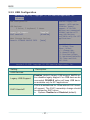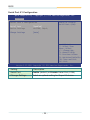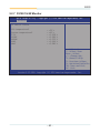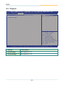
1
ELIT-1000 Series
Robust Box PC with
Intel Atom™ D2550 Platform
®
User’s Manual
Version 1.3
P/N: 4012100000130P
2013.04
Revision History
Version
Date
1.0
2012/04/06
initial release (except Ch5 & Appendix)
Description
1.0
2012/04/12
SSD: change to 40GB
1.0
2012/05/03
revise according to countersignature suggestion
1.0
2012/10/18
revise driver path; p.12 JPRS1
1.0
2012/10/24
add BIOS chapter
add 16GB SSD and 2GB memory into ordering
information
1.0
2012/10/26
1.0
2012/11/09
revise according to countersignature suggestion
1.1
2012/11/12
add CBL-3100-COM, RJ45 PLUG TO DB9M in
ordering information
1.2
2012/12/03
JPRS1: delete RS-485 Auto-flow off
1.2
2013/01/07
replace MM-3I-2G with MM-3I-4G in optional
information
revise spec as datasheet
add COM1~2 definition in Chapter 2
change to new User’s Manual format
change “JCOM2” to “COM2” in Ch3
1.2
2013/01/14
change COM1/2, JRSTB1, JPRS1 content in
Ch3
add section 4.3, Mount the Computer
update cover month
1.3
2013/04/15
add VMK-1000 in ch1.5.1
update ch1.3 spec
update BIOS chapter
Contents
Contents
Preface......................................................................................iii
Copyright Notice...............................................................iii
Declaration of Conformity................................................iii
CE.......................................................................................iii
FCC Class A......................................................................iii
RoHS..................................................................................iv
SVHC / REACH..................................................................iv
Important Safety Instructions...........................................v
Warning.............................................................................vi
Replacing the Lithium Battery.........................................vi
Technical Support.............................................................vi
Warranty...........................................................................vii
Chapter 1 - Introduction............................................................1
1.1 The Product.................................................................2
1.2 About This Manual......................................................3
1.3 Specifications.............................................................3
1.4 Inside the Package.....................................................4
1.5 Ordering Information..................................................5
1.5.1 Optional Accessories..............................................5
1.5.2 Configure-to-Order Service....................................5
1.6. Driver Installation Notes............................................6
Chapter 2 - System Overview...................................................7
2.1 Dimensions.................................................................8
2.2 Take A Tour..................................................................9
2.2.1 Front View................................................................9
2.2.2 Rear View..................................................................9
2.2.3 Side View..................................................................9
Chapter 3 - Engine of the Computer......................................11
3.1 Board Layout.............................................................12
3.2 Jumpers and Connectors........................................13
3.2.1 Jumpers..................................................................13
JBAT1.............................................................................. 13
JRSTB1........................................................................... 13
-i-
Contents
JPRS1.............................................................................. 14
JPCONN1........................................................................ 15
JPCONN2........................................................................ 15
3.2.2 Connectors.............................................................16
JLPC1.............................................................................. 16
COM1............................................................................... 16
COM2............................................................................... 17
Chapter 4 - Installation and Maintenance..............................19
4.1 Install Hardware........................................................20
4.1.1
4.1.2
4.1.3
4.1.4
Removing Bottom Cover.......................................20
Installing Memory Module.....................................22
Installing WiFi Module...........................................23
Installing Hard Disk Drive.....................................24
4.2 Access SD Card........................................................25
4.3 Mount the Computer.................................................26
Chapter 5 - BIOS...............................................................................29
5.1 Main...........................................................................30
5.2 Advanced...................................................................32
5.2.1
5.2.2
5.2.3
5.2.4
5.2.5
5.2.6
5.2.7
ACPI Settings.........................................................33
S5 RTC Wake Settings...........................................34
CPU Configuration.................................................35
IDE Configuration..................................................36
USB Configuration.................................................37
F81801 Super IO Configuration............................38
F81801 H/W Monitor..............................................40
5.3 Chipset......................................................................41
5.3.1 Host Bridge............................................................42
5.3.2 South Bridge..........................................................44
5.4 Boot............................................................................45
5.5 Security.....................................................................46
5.6 Save & Exit................................................................47
Appendix...........................................................................................49
Watchdog Timer (WDT) Setting......................................50
- ii -
Preface
Copyright Notice
All Rights Reserved.
The information in this document is subject to change without prior notice in
order to improve the reliability, design and function. It does not represent a
commitment on the part of the manufacturer.
Under no circumstances will the manufacturer be liable for any direct, indirect,
special, incidental, or consequential damages arising from the use or inability
to use the product or documentation, even if advised of the possibility of such
damages.
This document contains proprietary information protected by copyright. All
rights are reserved. No part of this document may be reproduced by any mechanical, electronic, or other means in any form without prior written permission of the manufacturer.
Declaration of Conformity
CE
The CE symbol on your product indicates that it is in compliance with the directives of the Union European (EU). A Certificate of Compliance is available
by contacting Technical Support.
This product has passed the CE test for environmental specifications when
shielded cables are used for external wiring. We recommend the use of
shielded cables. This kind of cable is available from ARBOR. Please contact
your local supplier for ordering information.
Warning
This is a class A product. In a domestic environment this product may cause
radio interference in which case the user may be required to take adequate
measures.
FCC Class A
This device complies with Part 15 of the FCC Rules. Operation is subject to
the following two conditions:
(1)This device may not cause harmful interference, and
(2)This device must accept any interference received, including interference
that may cause undesired operation.
NOTE:
This equipment has been tested and found to comply with the limits for a
Class A digital device, pursuant to Part 15 of the FCC Rules. These limits are
designed to provide reasonable protection against harmful interference when
the equipment is operated in a commercial environment. This equipment generates, uses, and can radiate radio frequency energy and, if not installed and
- iii -
Preface
used in accordance with the instruction manual, may cause harmful interference to radio communications. Operation of this equipment in a residential
area is likely to cause harmful interference in which case the user will be
required to correct the interference at his own expense.
RoHS
ARBOR Technology Corp. certifies that all components in its products are in
compliance and conform to the European Union’s Restriction of Use of Hazardous Substances in Electrical and Electronic Equipment (RoHS) Directive
2002/95/EC.
The above mentioned directive was published on 2/13/2003. The main purpose of the directive is to prohibit the use of lead, mercury, cadmium, hexavalent chromium, polybrominated biphenyls (PBB), and polybrominated diphenyl ethers (PBDE) in electrical and electronic products. Member states of the
EU are to enforce by 7/1/2006.
ARBOR Technology Corp. hereby states that the listed products do not contain unintentional additions of lead, mercury, hex chrome, PBB or PBDB that
exceed a maximum concentration value of 0.1% by weight or for cadmium
exceed 0.01% by weight, per homogenous material. Homogenous material
is defined as a substance or mixture of substances with uniform composition
(such as solders, resins, plating, etc.). Lead-free solder is used for all terminations (Sn(96-96.5%), Ag(3.0-3.5%) and Cu(0.5%)).
SVHC / REACH
To minimize the environmental impact and take more responsibility to the
earth we live, Arbor hereby confirms all products comply with the restriction of
SVHC (Substances of Very High Concern) in (EC) 1907/2006 (REACH --Registration, Evaluation, Authorization, and Restriction of Chemicals) regulated
by the European Union.
All substances listed in SVHC < 0.1 % by weight (1000 ppm)
- iv -
Preface
Important Safety Instructions
Read these safety instructions carefully
1. Read all cautions and warnings on the equipment.
2. Place this equipment on a reliable surface when installing. Dropping it or
letting it fall may cause damage
3. Make sure the correct voltage is connected to the equipment.
4. For pluggable equipment, the socket outlet should be near the equipment
and should be easily accessible.
5. Keep this equipment away from humidity.
6. The openings on the enclosure are for air convection and protect the equipment
from overheating. DO NOT COVER THE OPENINGS.
7. Position the power cord so that people cannot step on it. Do not place
anything over the power cord.
8. Never pour any liquid into opening. This may cause fire or electrical
shock.
9. Never open the equipment. For safety reasons, the equipment should be
opened only by qualified service personnel.
10. If one of the following situations arises, get the equipment checked by
service personnel:
a. The power cord or plug is damaged.
b. Liquid has penetrated into the equipment.
c. The equipment has been exposed to moisture.
d. The equipment does not work well, or you cannot get it to work according
to the user’s manual.
e. The equipment has been dropped or damaged.
f. The equipment has obvious signs of breakage.
11. Keep this User’s Manual for later reference.
-v-
Preface
Warning
The Box PC and its components contain very delicately Integrated Circuits
(IC). To protect the Box PC and its components against damage caused by
static electricity, you should always follow the precautions below when handling it:
1. Disconnect your Box PC from the power source when you want to work on
the inside.
2. Use a grounded wrist strap when handling computer components.
3. Place components on a grounded antistatic pad or on the bag that came
with the Box PC, whenever components are separated from the system.
Replacing the Lithium Battery
Incorrect replacement of the lithium battery may lead to a risk of explosion.
The lithium battery must be replaced with an identical battery or a battery type
recommended by the manufacturer.
Do not throw lithium batteries into the trashcan. It must be disposed of in
accordance with local regulations concerning special waste.
Technical Support
If you have any technical difficulties, please consult the user’s manual first
at: ftp://ftp.arbor.com.tw/pub/manual
Please do not hesitate to call or e-mail our customer service when you still cannot find out the answer.
http://www.arbor.com.tw
E-mail:[email protected]
- vi -
Preface
Warranty
This product is warranted to be in good working order for a period of one year
from the date of purchase. Should this product fail to be in good working order
at any time during this period, we will, at our option, replace or repair it at no
additional charge except as set forth in the following terms. This warranty does
not apply to products damaged by misuse, modifications, accident or disaster.
Vendor assumes no liability for any damages, lost profits, lost savings or any
other incidental or consequential damage resulting from the use, misuse of, or
inability to use this product. Vendor will not be liable for any claim made by any
other related party.
Vendors disclaim all other warranties, either expressed or implied, including but
not limited to implied warranties of merchantability and fitness for a particular
purpose, with respect to the hardware, the accompanying product’s manual(s)
and written materials, and any accompanying hardware. This limited warranty
gives you specific legal rights.
Return authorization must be obtained from the vendor before returned merchandise will be accepted. Authorization can be obtained by calling or faxing
the vendor and requesting a Return Merchandise Authorization (RMA) number.
Returned goods should always be accompanied by a clear problem description.
- vii -
This page is intentionally left blank.
- viii -
Introduction
1
Chapter 1
Introduction
-1-
Introduction
1.1 The Product
The Box PC, ELIT-1000 is targeted at many
different application fields. By adopting it,
you can pinpoint specific markets, such
as Thin Client, KIOSK, information booth,
GSM Server, environment-critical and
space-critical applications.
•
•
•
•
•
•
•
All-In-One Platform
The CPU, DRAM and even software
are integrated to provide a plug-and-play machine.
Compact-sized
The kernel of ELIT-1000 is FMB-i2508, which is a non-standard form
factor embedded board. The whole system consumes only a few
space.
Fanless and Modular CPU Board
By using a low power processor, the system does not have to rely on
fans, which are often unreliable and cause dust to circulate inside the
equipment. The modular design facilitates maintenance or possible
upgrades on the CPU board. Modular Box PC can be easily modified
to fit many different applications according to customers' requests.
Powerful Communication Capability
The ELIT-1000 provides COM, Ethernet, USB, Mini Card slot, SD and
DVI.
Numerous Display/Video Output
Integrated with Intel® HD Graphics core, ELIT-1000 improves
graphics and 3D rendering performance and supports display/video
output options includes DVI-I and DVI-D.
Advanced Storage Solution
ELIT-1000 comes with SD (Secure Digital) slot, which offers a better,
faster and more cost-effective expansibilities for various applications.
Trustworthy
The onboard Watchdog Timer can invoke an NMI or system RESET
when your application loses control over the system.
-2-
Introduction
1.2 About This Manual
This manual is meant for experienced users and integrators with hardware
knowledge of personal computers. If you are not sure about the description
herein, consult your vendor before further handling.
We recommend you keep one copy of this manual for the quick reference for any
necessary maintenance in the future. Thank you for choosing ARBOR products.
1.3 Specifications
System Kernel
Processor
Soldered onboard Intel® Atom™ D2550 1.86GHz
processor
BIOS
AMI Flash BIOS
Chipset
Intel® NM10 PCH
Graphics
Integrated Intel® GMA 3650
System Memory
1 x 204-pin DDR3 SO-DIMM Socket, supporting
800/1066MHz SDRAM up to 4GB
Serial ATA
1 x Serial ATA port with 300MB/s HDD transfer rate
Ethernet Controller 2 x Realtek 8111 Gigabit Ethernet controllers
Watchdog Timer
1 ~ 255 levels reset
I/O Ports
Serial Port
• 2 x RJ-45 ports
• Support COM1 RS-232
• Support COM2 RS-232/422/485 selectable; RS-485
supports auto-flow control
Expansion Bus
1 x Mini-card slot for optional WiFi module
USB Port
4 x USB 2.0 ports
LAN
2 x RJ-45 ports for Gigabit Ethernet
Video Port
• 1 x DVI-I female connector for Digital Video output
• 1 x DVI-D female connector for Digital Video output
Audio
Mic-in/ 2 x Line-out (500mW pre-amplified)
Storage
Type
• 1 x 2.5” drive bay for HDD/SSD
• 1 x SD socket, which can be outside accessible
-3-
Introduction
Qualification
FCC
Class A certified
CE
Certified
Environmental
Operating Temp.
-25 ~ 55ºC (-13 ~ 131ºF), ambience w/ air flow
Storage Temp.
-40 ~ 85ºC (-40 ~ 185ºF)
Relative Humidity
10 ~ 95% @ 40oC (non-condensing)
Vibration
3 Grms/5 ~ 500 Hz/random operation
Shock & Crash
• Operating 20G (11ms), Non-operating 60G with HDD
• Operating 40G (11ms), Non-operating 80G with SSD
Mechanical
Construction
Aluminum alloy
Mounting
Support VESA-mount/wall-mounting
Weight
0.93Kg (2.05lb) / 1.1Kg (2.42lb)
Dimensions
(W x D x H)
System = 188 x 149.5 x 30mm (7.4” x 5.88” x 1.18”)
Packing = 304 x 294 x 355mm (11.97” x 11.57” x
13.98”)
Power Requirement
Power Input
DC 19V input by 2.5mm power jack
Power
Consumption
Max. 25W
1.4 Inside the Package
Upon opening the package, carefully inspect the contents. If any of the items
is missing or appears damaged, contact your local dealer or distributor. The
package should contain the following items:
1 x ELIT-1000 Robust System
1 x Driver CD
1 x User’s Manual
-4-
Introduction
1.5 Ordering Information
ELIT-1000
Barebone system w/o storage device and memory
ELIT-1000-16S2G
Box PC w/ 16GB SSD and 2GB memory
1.5.1 Optional Accessories
The following items are normally optional, but some vendors may include
them as a standard package, or some vendors may not carry all the items.
PAC-B065W-2
65W AC/DC adapter kit
CBL-3100-COM
COM converter cable
VMK-1000
VESA mount kit for ELIT-1xxx series
1.5.2 Configure-to-Order Service
SSD-25032
Memoright 2.5” 32GB SATAII SSD kit
SSD-25016
Memoright 2.5” 16GB SATAII SSD kit
MM-3C-4G
DDR3-1333 4GB SDRAM
MM-3C-2G
DDR3-1333 2GB SDRAM
WIFI-IN1300
Intel® Centrino® Advanced-N 6205 WiFi module w/ 20cm internal wiring
ANT-D11
1 x WiFi Dual-band 2.4G/5G antenna
-5-
Introduction
1.6. Driver Installation Notes
ELIT-1000 supports the operating systems of Windows XP and Windows 7. For
Windows O.S., find the necessary device drivers on the CD that comes with your
purchase. For different O.S., the installation of drivers/utilities may vary slightly,
but generally they are similar. DO follow the sequence below to install the drivers
to prevent errors:
Chipset→VGA→Audio→LAN
Paths to find various drivers on the CD are listed below. Users should execute
each driver in respective parentheses and follow its directions to complete every
installation.
Windows XP
Driver
Path
CHIPSET
\Chipset\WinXP_32 (infinst_autol.exe)
VGA
\VGA\INTEL_XP_32 (WindowsDriverSETUP.cmd)
LAN
\LAN\Realtek_8111E_XP_32 (setup.exe)
AUDIO
\Audio ALC662\REALTEK_HD\XP_WINDOWS_R267 (WDM_R267.
exe)
Windows 7-32 bit
Driver
Path
CHIPSET
\Chipset\Win7_x86 (infinst_autol.exe)
VGA
\VGA\Win7_x86 (Setup.exe)
LAN
\LAN\Install_Win7_7048_09162011 (setup.exe)
AUDIO
\Audio ALC662\Win 7(32, 64 bits) Driver_R2.66 (Vista_Win7_R266.
exe)
-6-
System Overview
2
Chapter 2
System Overview
-7-
System Overview
2.1 Dimensions
The following illustration shows the dimension of ELIT-1000, with the measurements in width, depth, and height called out.
215.70
200.00
188.00
R3
.00
20.00
Ø11.00
100.00
30.00
31.30
25.00
50.00
149.50
NUT UNC #6-32
-8-
Unit: mm
System Overview
2.2 Take A Tour
The computer has some I/O ports, status LED lights and controls on the front
panel. The following illustrations show the front panel and rear panel of ELIT1000, with all the components on them called out.
2.2.1 Front View
ACPI Power Button USBs
Antenna
PWR & HDD
Hole
Indicators
MIC
COM Ports
SD Slot
Antenna
Hole
2.2.2 Rear View
Take a look a the rear side of ELIT-1000.
DC-IN
LINE-OUT
DVI-D
DVI-I
2.2.3 Side View
-9-
LAN Ports USB Ports
This page is intentionally left blank.
- 10 -
Engine of the Computer
3
Chapter 3
Engine of the
Computer
- 11 -
Engine of the Computer
3.1 Board Layout
The main board FMB-i2508 forms the engine of the ELIT-1000. This section
will provide an thorough views of this board.
JLPC1
JPCONN1
JPRS1
JPCONN2
COM2
COM1
JRSTB1
JBAT1
- 12 -
Engine of the Computer
3.2 Jumpers and Connectors
The following in this chapter will explicate each of the components one-by-one.
3.2.1 Jumpers
JBAT1
Function: Clear CMOS Setting
Jumper Type:
Onboard 2.54mm pitch 1x3-pin
header
Setting:
Pin
Function
1-2
Keeps CMOS
(Default)
1
2
3
1
2-3
Clears CMOS
2
3
JRSTB1
Function: AT/ATX Power Mode Selector
Jumper Type:
Onboard 2x4-pin 2.0mm pin
header
Setting:
Pin
Function
NC
ATX Mode
(Default)
1-2
3-4
External
Reset
AT Mode
1
2
3
1
1
4
2
2
3
3
1
4
4
2
2
2
3
1
3
3
4
4
2
4
1
2
3
4
3
4
1
2
3
4
1
1
- 13 -
Engine of the Computer
JPRS1
Function: COM2 RS232/422/485 Setting
Onboard 2x6-pin 2.0mm pin
header
Jumper Type:
Setting:
Pin
RS-232 Mode RS-422 RS-485 Mode
(Default)
Mode w/ Auto-flow
1-2
SHORT
OPEN
OPEN
3-4
OPEN
SHORT
OPEN
5-6
OPEN
OPEN
SHORT
7-8
OPEN
OPEN
OPEN
9-10
OPEN
OPEN
OPEN
11-12
SHORT
OPEN
OPEN
1
2
1
2
1
12
1
2
12
2
1
12
1
2
12
2
1
2
1
2
3
4
3
4
3
34
3
4
34
4
3
34
3
4
34
4
3
4
3
4
5
6
5
6
5
56
5
6
56
6
5
56
5
6
56
6
5
6
5
6
7
8
7
8
7
78
7
8
78
8
7
78
7
8
78
8
7
8
7
8
9
10
9
10
9
910
9
10
910
10
9
910
9
10
910
10
9
10
9
10
11
12
11
12
11
1112
11 12
1112
12
11
11
12
11
12
11
12
12
11
12
11
12
Termination Setting for COM2 in RS-422/485 mode
RS-422
Pin
RS-485
Termination Termination Termination Termination
2
2
1
2
1
On 1
Off
(Default)
On
Off1 (Default)
4
4
3
7-8
9-10
3
3
SHORT 7
6
8
OPEN
8
7
9
10
9
5
SHORT11
5
6
10
OPEN
12
12
11
4
OPEN
5
6
OPEN
8
7
SHORT
9
10
OPEN
12
11
3
5
2
4
6
7
8
9
10
11
12
1
2
1
2
1
2
1
2
1
2
1
2
1
2
1
2
3
4
3
4
3
4
3
4
3
4
3
4
3
4
3
4
5
6
5
6
5
6
5
6
5
6
5
6
5
6
5
6
7
8
7
8
7
8
7
8
7
8
7
8
7
8
7
8
9
10
9
10
9
10
9
10
9
10
9
10
9
10
9
10
11
12
11
12 11
12
11
12
11
12
11
12 11
12
11
12
1
2
1
2
1
2
1
2
3
4
3
4
3
4
3
4
5
6
5
6
5
6
5
6
7
8
7
8
7
8
7
8
9
10
9
10
9
10
9
10
11
12
11
12
11
12
11
12
- 14 -
Engine of the Computer
JPCONN1
Function: COM2 RS232/422/485 Setting
Jumper Type:
Onboard 2x3-pin 2.0mm pin
header
Setting:
RS-232 Mode RS-422
(Default)
Mode
5
Short 1-3
Pin
2-4
3
1
3-5
4-6
RS-485
Mode
5
3
1
3-5
6
4
2
4-6
6
4
2
5
3
1
5
3
1
5
3
1
6
4
2
6
4
2
6
4
2
5
3
1
6
4
2
JPCONN2
Function: COM2 RS232/422/485 Setting
Jumper Type:
Onboard 2x3-pin 2.0mm pin
header
Setting:
RS-232 Mode RS-422
(Default)
Mode
5
Short 1-3
Pin
2-4
3
1
3-5
4-6
RS-485
Mode
5
3
1
3-5
4-6
6
4
2
6
4
2
5
3
1
5
3
1
5
3
1
6
4
2
6
4
2
6
4
2
5
3
1
6
4
2
- 15 -
Engine of the Computer
3.2.2 Connectors
JLPC1
Function: External 80 Port Pin Header
Jumper Type:
Onboard 2.00mm pitch 10-pin
header
Setting:
Pin Description
Pin
Description
1
CLOCK
2
GND
3
FRAME
4
LAD0
5
RESET
6
NC
7
LAD3
8
LAD2
9
VCC3
10
LAD1
COM1
Function: Serial Port; only supports RS-232 mode
Setting:
COM1 Pin
RS-232
Description
1
DSRN2
2
DCDN2
3
DTRN2
4
GND
5
SIN2
6
SOUTN2
7
CTSN2
8
RTSN2
- 16 -
Engine of the Computer
COM2
Function: Serial Port; COM2 is RS-232/422/485 selectable; RS-485
mode supports auto-flow control function.
Setting:
COM2
Pin
RS-232
Def.
RS-422
Def.
RS-485
Def.
1
DSRN2
COM2_SEL1(TX+) COM2_SEL1 (TX+)
2
DCDN2
COM2_SEL2(TX-) COM2_SEL2 (TX-)
3
DTRN2
N/A
N/A
4
GND
N/A
N/A
5
SIN2
N/A
N/A
6
SOUTN2
N/A
N/A
7
CTSN2
COM2_SEL7(RX+)
N/A
8
RTSN2
COM2_SEL7(RX-)
N/A
- 17 -
This page is intentionally left blank.
- 18 -
Installation and Maintenance
4
Chapter 4
Installation and
Maintenance
- 19 -
Installation and Maintenance
4.1 Install Hardware
ELIT-1000 is designed to be modular, slim and lightweight for easier
maintenance. The following sections describe simple hardware installations.
4.1.1 Removing Bottom Cover
1. Carefully place the Box PC upside down. Unscrew the screw securing the
bottom cover with cross-head screwdriver. Retain it safely for later use, so
do the rest components we are going to remove.
2. Turn to the front panel and loosen two screws close to botoom plate. Then,
turn to another side to unscrew two screws at corners. Locate four hex
standoffs beside DVI-I & DVI-D. Unscrew them with special hex driver.
You also have to take off washer and nut from DC-IN connector. Carefully
unmount the one-piece bottom cover from main unit.
- 20 -
Installation and Maintenance
3. Gently pull the bottom cover upward.
Mini-card Socket
Drive Bay
Memory Socket
To install memory module, see 4.1.2 Installing Memory Module on page 22.
To install WiFi module, see 4.1.3 Installing WiFi Module on page 23.
To install hard disc drive, see 4.1.4 Installing Hard Disk Drive on page 24.
- 21 -
Installation and Maintenance
4.1.2 Installing Memory Module
Side notch
Latch knob
Latch claw
Latch section
Latch arm
Polarizing key
Key
To install the Memory module, locate the Memory SO-DIMM slot on the
board and perform as below:
1. Adjust the socket polarizing key and the board key to the same direction.
2. Insert the board obliquely. Moreover, lay the board in parallel to the
opening at angle of 20o to 30o, and softly insert the board so as to hit the
socket bottom. Stopping insertion halfway will result in improper insertion.
3. Applying the board side notch in parallel to the socket bottom so that
the board position cannot be displaced, press the board side notch up,
and fix it to the latch portion at both socket edges. Press the board side
notch, and release the notch with a snap “click” tone, if the printed board
exceeds the latch claw head.
1
2
3
Procedures for board extraction
Apply the thumb nail to the latch knob at both socket edges. Forcibly widen
the latch knobs to right and left ways, and release the latch. Then draw the
board out along an angle where the board is raised.
- 22 -
Installation and Maintenance
4.1.3 Installing WiFi Module
1. Locate Mini-card socket.
2. Insert WiFi module into its slot at a slanted angle. Remember to align the
notch with the break on slot.
3. And then, secure two screws to fasten the module.
1
3
2
- 23 -
Installation and Maintenance
4.1.4 Installing Hard Disk Drive
1. Fasten HDD on its bracket.
2. Insert the bracket into driver bay and secure its corners from two screws at
right side first.
- 24 -
Installation and Maintenance
4.2 Access SD Card
1. Make sure you have turned off the power before inserting or ejecting the
SD card (if OS is installed on SD card).
2. Locate the SD card slot on the front panel.
3. Insert your SD card into the slot. To remove the SD card, push that
inwards to pop it out.
- 25 -
Installation and Maintenance
4.3 Mount the Computer
Integrate the computer to where it works by mounting it to a wall in the
surroundings or to the rear of a display monitor. Mounting the computer to
the rear of a display monitor relies on VMK-1000, a VESA mount kit, which
is available on your option. Follow the guide below to integrate the computer
with a display monitor using VMK-1000.
1. Prepare the VMK-1000 VESA mount kit, which includes two adapters.
Halfway fasten two screws to each of the adapter as marked in the illustration
below.
Halfway fasten the two screws.
2. Fix VMK-1000 on place you want to fix (in this example, display monitor)
through VESA-100 x 100 screw holes.
- 26 -
Installation and Maintenance
3. Hang the computer on VMK-1000 and tighten screws at corners to the end.
4. Viewing from the opposite side, it would be like this:
Push ELIT-1000 into
VMK-1000 through
the central round
holes.
Move ELIT-1000 downwards,
make sure it’s unmovable
prior to tightening screws at
corners.
- 27 -
This page is intentionally left blank.
- 28 -
BIOS
5
Chapter 5
BIOS
- 29 -
BIOS
5.1 Main
The AMI BIOS provides a Setup utility program for specifying the system
configurations and settings. The BIOS RAM of the system stores the Setup
utility and configurations. When you turn on the computer, the AMI BIOS is
immediately activated. To enter the BIOS SETUP UTILITY, press “Delete”
once the power is turned on. When the computer is shut down, the battery on
the motherboard supplies the power for BIOS RAM.
The Main Setup screen lists the following information:
Aptio Setup Utility - Copyright (C) 2012 American Megatrends, Inc.
Main Advanced Chipset Boot Security Save & Exit
BIOS Information
BIOS Vendor
Core Version
Compliancy
BIOS version
Build Date and Time
American Megatrends
4.6.5.3
UEFI 2.3; PI 1.2
ELIT-1000 1.12
12/10/2012 16:09:17
System Date
System Time
[Mon 04/15/2013]
[17:38:10]
Access Level
Administrator
Set the Date. Use Tab
to switch between
Data elements.
→←: Select Screen
↓↑: Select Item
Enter: Select
+/-: Change Opt.
F1: General Help
F2: Previous Values
F9: Optimized Defaults
F10: Save and Exit
ESC: Exit
Version 2.15.1226. Copyright (C) 2012 American Megatrendes, Inc.
Setting
Description
BIOS Information
BIOS Vendor
displays vendor name
Core Version
displays current core version information
Compliancy
displays compliant format
BIOS Version
displays current BIOS version information
Build Date and Time
the date that the BIOS version was made/updated
- 30 -
BIOS
System Date
Set the system date. Note that the ‘Day’ automatically changes when you set the date.
► ► The date format is: Day: Sun to Sat
Month: 1 to 12
Date: 1 to 31
Year: 1998 to 2099
Set the system time.
System Time
► ► The time format is: Hour: 00 to 23
Minute: 00 to 59
Second: 00 to 59
Key Commands
BIOS Setup Utility is mainly a key-based navigation interface. Please refer to
the following key command instructions for navigation process.
Keystroke
Function
◄ ►
Move to highlight a particular configuration screen from
the top menu bar / Move to highlight items on the screen
▼ ▲
Move to highlight previous/next item
Enter
Select and access a setup item/field
Esc
On the Main Menu – Quit the setup and not save
changes into CMOS (a message screen will display
and ask you to select “OK” or “Cancel” for exiting and
discarding changes. Use “←” and “→” to select and press
“Enter” to confirm)
On the Sub Menu – Exit current page and return to main
menu
Page Up / +
Increase the numeric value on a selected setup item /
make change
Page Down -
Decrease the numeric value on a selected setup item /
make change
F1
Activate “General Help” screen
F10
Save the changes that have been made in the setup and
exit. (a message screen will display and ask you to select
“OK” or “Cancel” for exiting and saving changes. Use “←”
and “→” to select and press “Enter” to confirm)
- 31 -
BIOS
5.2 Advanced
The “Advanced” setting page provides you the options to configure the details
of your hardware, such as ACPI, CPU, IDE, USB and Super IO.
Aptio Setup Utility - Copyright (C) 2012 American Megatrends, Inc.
Main Advanced Chipset Boot Security Save & Exit
►
►
►
►
►
►
►
Enable or Disable Boot
Option for Legacy
Network Devices.
ACPI Settings
S5 RTC Wake Settings
CPU Configuration
IDE Configuration
USB Configuration
F81801 Super IO Configuration
F81801 H/W Monitor
→←: Select Screen
↓↑: Select Item
Enter: Select
+/-: Change Opt.
F1: General Help
F2: Previous Values
F9: Optimized Defaults
F10: Save and Exit
ESC: Exit
Version 2.15.1226. Copyright (C) 2012 American Megatrendes, Inc.
Setting
Description
ACPI Settings
See Section 5.2.1
S5 RTC Wake Settings
See Section 5.2.2
CPU Configuration
See Section 5.2.3
IDE Configuration
See Section 5.2.4
USB Configuration
See Section 5.2.5
F81801 Super IO Configuration
See Section 5.2.6
F81801 H/W Monitor
See Section 5.2.7
- 32 -
BIOS
5.2.1 ACPI Settings
Aptio Setup Utility - Copyright (C) 2012 American Megatrends, Inc.
Advanced
ACPI Settings
Enable ACPI Auto Configuration [Disabled]
Enable Hibernation
ACPI Sleep State
Enables or Disables
BIOS ACPI Auto
Configuration.
[Enabled]
[S1 (CPU Stop Clock)]
→←: Select Screen
↓↑: Select Item
Enter: Select
+/-: Change Opt.
F1: General Help
F2: Previous Values
F9: Optimized Defaults
F10: Save and Exit
ESC: Exit
Version 2.15.1226. Copyright (C) 2012 American Megatrendes, Inc.
Setting
Description
Enable ACPI Auto
Configuration
Enable or Disable (default) BIOS ACPI Auto Configuration.
Enable Hibernation
Enable (default) or Disable system ability to Hibernate (OS/S4 Sleep State). This option may be not
effective with some OS.
ACPI Sleep State
Select the highest ACPI sleep state the system will
enter when the SUSPEND button is pressed.
► ► Options: Suspend Disabled, S1 (CPU Stop
Clock) (default).
- 33 -
BIOS
5.2.2 S5 RTC Wake Settings
Enable system to wake from S5 using RTC alarm.
Aptio Setup Utility - Copyright (C) 2012 American Megatrends, Inc.
Advanced
Wake
Wake
Wake
Wake
system with Fixed Time
up hour
up minute
up second
[Disabled]
9
30
0
Wake system with Dynamic Time [Disabled]
Enable or disable
System wake on alarm
event. When enabled,
System will wake on
the hr::min::sec
specified
→←: Select Screen
↓↑: Select Item
Enter: Select
+/-: Change Opt.
F1: General Help
F2: Previous Values
F9: Optimized Defaults
F10: Save and Exit
ESC: Exit
Version 2.15.1226. Copyright (C) 2012 American Megatrendes, Inc.
Setting
Description
Wake system with
Fixed Time
Enable or Disable (default) System wake on alarm
event. When enabled, System will wake on the
hr::min::sec specified.
Wake up hour
select 0-23
For example enter 3 for 3am and 15 for 3pm
Wake up minute
0-59
Wake up second
0-59
Wake system with
Dynamic Time
Enable or Disable (default) System wake on alarm
event. When enabled, System will wake on the current time + Increase minute(s).
- 34 -
BIOS
5.2.3 CPU Configuration
Aptio Setup Utility - Copyright (C) 2012 American Megatrends, Inc.
Advanced
CPU Configuration
Processor Type
EMT64
Processor Speed
System Bus Speed
Ratio Status
Actual Ratio
System Bus Speed
Processor Stepping
Microcode Revision
L1 Cache RAM
L2 Cache RAM
Processor Core
Hyper-Threading
Hyper-Threading
Execute Disable Bit
Limit CPUID Maximum
Enabled for Windows XP
and Linux (OS
Intel(R) Atom(TM) CPU optimized for HyperThreading Technology)
Supported
and Disabled for other
1865 MHz
OS (OS not optimized
533 MHz
for Hyper-Threading
14
Technology).
14
533 MHz
30661
269
2x56 k
2x512 k
Dual
Supported
[Enabled]
[Enabled]
[Disabled]
→←: Select Screen
↓↑: Select Item
Enter: Select
+/-: Change Opt.
F1: General Help
F2: Previous Values
F9: Optimized Defaults
F10: Save and Exit
ESC: Exit
Version 2.15.1226. Copyright (C) 2012 American Megatrendes, Inc.
Setting
Description
Hyper-threading
Enabled (default) for Windows XP and Linux (OS
optimized for Hyper-threading Technology) and
Disabled for other OS (OS not optimized for Hyper-threading Technology).
Execute Disable Bit
XP can prevent certain classes of malicious buffer
overflow attacks when combined with a supporting OS (Windows Server 2003 SP1, Windows XP
SP2, SuSE Linux 9.2, RedHat Enterprise 3 Update
3.)
► ► Options: Enabled (default) and Disabled.
Limit CPUID Maximum
Disabled for Windows XP
► ► Options: Enabled and Disabled (default).
- 35 -
BIOS
5.2.4 IDE Configuration
Aptio Setup Utility - Copyright (C) 2012 American Megatrends, Inc.
Advanced
Not Present
Not Present
SATA Port0
SATA Port1
SATA Controller(s)
[Enabled]
Configure SATA as
Port0 Speed Limit
Port1 Speed Limit
[AHCI]
[No Limit]
[No Limit]
SATA
SATA
SATA
SATA
Port
Port
Port
Port
[Enabled]
[Enabled]
[Enabled]
[Enabled]
0
0 Hot Plug
1
1 Hot Plug
Misc Configuration for hard disk
SATA Ports (0-3)
Device Names if
Present and Enabled.
→←: Select Screen
↓↑: Select Item
Enter: Select
+/-: Change Opt.
F1: General Help
F2: Previous Values
F9: Optimized Defaults
F10: Save and Exit
ESC: Exit
Version 2.15.1226. Copyright (C) 2012 American Megatrendes, Inc.
Setting
SATA Controller(s)
Configure SATA as
Description
SATA Ports (0-3) Device Names if Present and Enabled.
► ► Options: Enabled (default) and Disabled.
Select a configuration for SATA Controller.
► ► Options: IDE, AHCI (default).
Select Port0/1 AHCI Speed Limit.
Port0/1 Speed Limit
► ► Options: No Limit (default), GEN1 Rate, Gen2
Port 0/1
Enable (default) or Disable SATA Port.
Port 0/1 Hot Plug
Rate
Designates this port as Hot Pluggable.
► ► Options: Enabled (default) and Disabled.
- 36 -
BIOS
5.2.5 USB Configuration
Aptio Setup Utility - Copyright (C) 2012 American Megatrends, Inc.
Advanced
USB Configuration
USB Devices:
1 Drive, 1 Keyboard, 1 Mouse
Legacy USB Support
EHCI Hand-off
[Enabled]
[Disabled]
Mass Storage Devices:
Generic STORAGE DEVICE 9454
[Auto]
Enables Legacy USB
support. AUTO option
disables legacy
support if no USB
devices are connected.
DISABLE option will
keep USB devices
available only for EFI
applications.
→←: Select Screen
↓↑: Select Item
Enter: Select
+/-: Change Opt.
F1: General Help
F2: Previous Values
F9: Optimized Defaults
F10: Save and Exit
ESC: Exit
Version 2.15.1226. Copyright (C) 2012 American Megatrendes, Inc.
Setting
Description
USB Devices:
Legacy USB Support
Enables (default) Legacy USB support. AUTO option disables legacy support if no USB devices are
connected. DISABLE option will keep USB devices available only for EFI applications.
EHCI Hand-off
This is a workaround for OSes without EHCI handoff support. The EHCI ownership change should
be claimed by EHCI driver.
► ► Options: Enabled and Disabled (default).
- 37 -
BIOS
Mass Storage Devices:
Generic STORAGE
DEVICE 9454
Mass storage device emulation type. ‘AUTO’ enumerates devices less than 530MB as floppies.
Forced FDD option can be used to force HDD formatted drive to boot as FDD (e.g. ZIP drive).
► ► Options: Auto (default), Floppy, Forced FDD,
Hard Disk, CD-ROM
5.2.6 F81801 Super IO Configuration
Aptio Setup Utility - Copyright (C) 2012 American Megatrends, Inc.
Advanced
Set Parameters of
Serial Port 0 (COMA)
F81801 Super IO Configuration
F81801 Super IO Chip
► Serial Port 0 Configuration
► Serial Port 1 Configuration
Power On After Power Fail
F81801
[Power On]
→←: Select Screen
↓↑: Select Item
Enter: Select
+/-: Change Opt.
F1: General Help
F2: Previous Values
F9: Optimized Defaults
F10: Save and Exit
ESC: Exit
Version 2.15.1226. Copyright (C) 2012 American Megatrendes, Inc.
Setting
Description
Serial Port 0/1 Configuration
See Next Tab
Power On After Power Fail
Specify what state to go to when power is
re-applied after a power failure.
► ► Options: Power Off, Power On (default), Last State
- 38 -
BIOS
Serial Port 0/1 Configuration
Aptio Setup Utility - Copyright (C) 2012 American Megatrends, Inc.
Advanced
Enable or Disable
Serial Port (COM)
Serial Port 0 Configuration
Serial Port
Device Settings
[Enabled]
IO=3F8h; IRQ=4;
Change Settings
[Auto]
→←: Select Screen
↓↑: Select Item
Enter: Select
+/-: Change Opt.
F1: General Help
F2: Previous Values
F9: Optimized Defaults
F10: Save and Exit
ESC: Exit
Version 2.15.1226. Copyright (C) 2012 American Megatrendes, Inc.
Setting
Description
Serial Port
Enable (default) or Disable Serial Port (COM)
Change Settings
Select an optimal setting for Super IO device.
- 39 -
BIOS
5.2.7 F81801 H/W Monitor
Aptio Setup Utility - Copyright (C) 2012 American Megatrends, Inc.
Advanced
Pc Health Status
CPU temperature1
System temperature2
3.3V
VCORE
VDIMM
VSB3
VBAT
:
:
:
:
:
:
:
+52˚c
+45˚c
+3.328
+1.184
+1.552
+3.344
+3.280
V
V
V
V
V
→←: Select Screen
↓↑: Select Item
Enter: Select
+/-: Change Opt.
F1: General Help
F2: Previous Values
F9: Optimized Defaults
F10: Save and Exit
ESC: Exit
Version 2.15.1226. Copyright (C) 2012 American Megatrendes, Inc.
- 40 -
BIOS
5.3 Chipset
Aptio Setup Utility - Copyright (C) 2012 American Megatrends, Inc.
Main Advanced Chipset Boot Security Save & Exit
Host Bridge Parameters
► Host Bridge
► South Bridge
→←: Select Screen
↓↑: Select Item
Enter: Select
+/-: Change Opt.
F1: General Help
F2: Previous Values
F9: Optimized Defaults
F10: Save and Exit
ESC: Exit
Version 2.15.1226. Copyright (C) 2012 American Megatrendes, Inc.
Setting
Description
Host Bridge
See Section 5.3.1
South Bridge
See Section 5.3.2
- 41 -
BIOS
5.3.1 Host Bridge
Aptio Setup Utility - Copyright (C) 2012 American Megatrends, Inc.
Chipset
Config Intel IGD
Settings.
► Intel IGD Configuration
******* Memory Information *******
1067 MHz(DDR3)
Memory Frequency
4096 MB
Total Memory
Not Present
DIMM#0
4096 MB
DIMM#1
→←: Select Screen
↓↑: Select Item
Enter: Select
+/-: Change Opt.
F1: General Help
F2: Previous Values
F9: Optimized Defaults
F10: Save and Exit
ESC: Exit
Version 2.15.1226. Copyright (C) 2012 American Megatrendes, Inc.
Setting
Intel IGD Configuration
Description
See Next Tab
- 42 -
BIOS
Intel IGD Configuration
Aptio Setup Utility - Copyright (C) 2012 American Megatrends, Inc.
Chipset
Intel IGD Configuration
IGFX - Boot Type
[DVI-I]
Select the Video
Device which will be
activated during POST.
This has no effect if
external graphics
present.
→←: Select Screen
↓↑: Select Item
Enter: Select
+/-: Change Opt.
F1: General Help
F2: Previous Values
F9: Optimized Defaults
F10: Save and Exit
ESC: Exit
Version 2.15.1226. Copyright (C) 2012 American Megatrendes, Inc.
Setting
IGFX - Boot Type
Description
Select the Video Device which will be activated during
POST. This has no effect if external graphics present.
► ► Options: DVI-I (default) and DVI-D.
- 43 -
BIOS
5.3.2 South Bridge
Aptio Setup Utility - Copyright (C) 2012 American Megatrends, Inc.
Chipset
High Precision Event Timer Configuration
[Enabled]
High Precision Timer
Enable or Disable the
High Precision Event
Timer.
→←: Select Screen
↓↑: Select Item
Enter: Select
+/-: Change Opt.
F1: General Help
F2: Previous Values
F9: Optimized Defaults
F10: Save and Exit
ESC: Exit
Version 2.15.1226. Copyright (C) 2012 American Megatrendes, Inc.
Setting
Description
High Precision Timer
Enable (default) or Disable the High Precision Event Timer.
SLP_S4 Assertion Width
Select a minimum assertion width of the SLP_
S4# signal.
► ► Options: 1-2 (default)/2-3/3-4/4-5 Seconds
- 44 -
BIOS
5.4 Boot
Aptio Setup Utility - Copyright (C) 2012 American Megatrends, Inc.
Main Advanced Chipset Boot Security Save & Exit
Boot Configuration
Bootup NumLock State
Quiet Boot
Fast Boot
[On]
[Disabled]
[Enabled]
Select the Keyboard
NumLock state
Boot Option Priorities
→←: Select Screen
↓↑: Select Item
Enter: Select
+/-: Change Opt.
F1: General Help
F2: Previous Values
F9: Optimized Defaults
F10: Save and Exit
ESC: Exit
Version 2.15.1226. Copyright (C) 2012 American Megatrendes, Inc.
Setting
Description
Bootup NumLock
State
► ► Options: On (default), Off
Select the keyboard NumLock state
Quiet Boot
Enable or Disable (default) Quiet Boot option.
Fast Boot
Enable (default) or Disable boot with initialization
of a minimal set of devices required to launch active
boot option. Has no effect for BBS boot options.
- 45 -
BIOS
5.5 Security
The Security menu sets up the administrator password. Once an administrator
password is set up, this BIOS SETUP utility is limited to access and will ask for
the password each time any access is attempted.
Aptio Setup Utility - Copyright (C) 2012 American Megatrends, Inc.
Main Advanced Chipset Boot Security Save & Exit
Set Administrator
Password
Password Description
Minimum length
Maximum length
3
20
Administrator Password
→←: Select Screen
↓↑: Select Item
Enter: Select
+/-: Change Opt.
F1: General Help
F2: Previous Values
F9: Optimized Defaults
F10: Save and Exit
ESC: Exit
Version 2.15.1226. Copyright (C) 2012 American Megatrendes, Inc.
Setting
Administrator
Password
Description
To set up an administrator password:
1. Select Administrator Password.
The screen then pops up an Create New Password dialog.
2. Enter your desired password that is no less than
3 characters and no more than 20 characters.
3. Hit [Enter] key to submit.
- 46 -
BIOS
5.6 Save & Exit
Aptio Setup Utility - Copyright (C) 2012 American Megatrends, Inc.
Main Advanced Chipset Boot Security Save & Exit
Reset system setup
after saving the
changes.
Save Changes and Exit
Discard Changes and Exit
Restore Defaults
Boot Override
→←: Select Screen
↓↑: Select Item
Enter: Select
+/-: Change Opt.
F1: General Help
F2: Previous Values
F9: Optimized Defaults
F10: Save and Exit
ESC: Exit
Version 2.15.1226. Copyright (C) 2012 American Megatrendes, Inc.
Setting
Description
Saves the changes and resets the system.
Save Changes and
► ► Enter the item and then a dialog box pops up:
Exit
Save configuration and exit?
Exit system setup without saving any changes.
Discard Changes and
► ► Enter the item and then a dialog box pops up:
Exit
Quit without saving?
Restore/Load Default values for all the setup options.
Restore Defaults
► ► Enter the item and then a dialog box pops up:
Load Optimized Defaults?
Boot Override presents a list of boot devices
Boot Override
on screen. Select the device to boot up the system
regardless of the currently configured boot priority.
- 47 -
This page is intentionally left blank.
- 48 -
Appendix
Appendix
- 49 -
Appendix
Watchdog Timer (WDT) Setting
WDT is widely applied to industry computers to monitor activities of CPU. The
programmed application triggers WDT with adequate timer setting depending
on its requirement. Before WDT counts down to zero, the functional system
will reset the counter. In case the WDT counter is not reset by an abnormal
system, it will counts down to zero and then reset the system automatically.
This computer supports the watchdog timer up to 255 levels for users for
software programming. Below please take the source code written in C for a
WDT application example.
outportb(0x4e, 0x87);
outportb(0x4e, 0x87);
/* initial IO port */
/* twice, */
outportb(0x4e, 0x07);
outportb(0x4e+1, 0x07);
outportb(0x4e, 0xf5);
outportb(0x4e+1, 0x40);
outportb(0x4e, 0xf0);
outportb(0x4e+1, 0x81);
outportb(0x4e, 0xf6);
outportb(0x4e+1, 0x05);
outportb(0x4e, 0xf5);
outportb(0x4e+1, 0x20);
/*
/*
/*
/*
/*
/*
/*
/*
/*
/*
outportb(0x4e, 0xAA);
/* stop program , Exit */
point to logical device */
select logical device 7 */
select offset f5h */
set bit5 = 1 to clear bit5 */
select offset f0h */
set bit7 =1 to enable WDTRST# */
select offset f6h */
update offset f6h to 0ah :10sec */
select offset f5h */
set bit5 = 1 enable watch dog time */
- 50 -
This page is intentionally left blank.
- 51 -