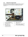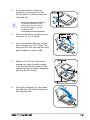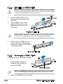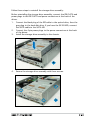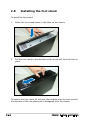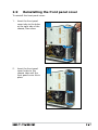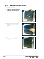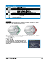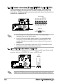
1
P1/P2-P5945GC
ASUS PC (Desktop Barebone)
User Guide
E3310
First Edition
July 2007
Copyright © 2006 ASUSTeK COMPUTER INC. All Rights Reserved.
No part of this manual, including the products and software described in it, may be reproduced,
transmitted, transcribed, stored in a retrieval system, or translated into any language in any form
or by any means, except documentation kept by the purchaser for backup purposes, without the
express written permission of ASUSTeK COMPUTER INC. (“ASUS”).
Product warranty or service will not be extended if: (1) the product is repaired, modified or
altered, unless such repair, modification of alteration is authorized in writing by ASUS; or (2) the
serial number of the product is defaced or missing.
ASUS PROVIDES THIS MANUAL “AS IS” WITHOUT WARRANTY OF ANY KIND, EITHER EXPRESS
OR IMPLIED, INCLUDING BUT NOT LIMITED TO THE IMPLIED WARRANTIES OR CONDITIONS OF
MERCHANTABILITY OR FITNESS FOR A PARTICULAR PURPOSE. IN NO EVENT SHALL ASUS,
ITS DIRECTORS, OFFICERS, EMPLOYEES OR AGENTS BE LIABLE FOR ANY INDIRECT, SPECIAL,
INCIDENTAL, OR CONSEQUENTIAL DAMAGES (INCLUDING DAMAGES FOR LOSS OF PROFITS, LOSS
OF BUSINESS, LOSS OF USE OR DATA, INTERRUPTION OF BUSINESS AND THE LIKE), EVEN IF ASUS
HAS BEEN ADVISED OF THE POSSIBILITY OF SUCH DAMAGES ARISING FROM ANY DEFECT OR
ERROR IN THIS MANUAL OR PRODUCT.
SPECIFICATIONS AND INFORMATION CONTAINED IN THIS MANUAL ARE FURNISHED FOR
INFORMATIONAL USE ONLY, AND ARE SUBJECT TO CHANGE AT ANY TIME WITHOUT NOTICE, AND
SHOULD NOT BE CONSTRUED AS A COMMITMENT BY ASUS. ASUS ASSUMES NO RESPONSIBILITY
OR LIABILITY FOR ANY ERRORS OR INACCURACIES THAT MAY APPEAR IN THIS MANUAL,
INCLUDING THE PRODUCTS AND SOFTWARE DESCRIBED IN IT.
Products and corporate names appearing in this manual may or may not be registered
trademarks or copyrights of their respective companies, and are used only for identification or
explanation and to the owners’ benefit, without intent to infringe.
ii
Table of contents
Notices................................................................................................. vi
Safety information...............................................................................vii
About this guide..................................................................................viii
System package contents..................................................................... x
Chapter 1: System Introduction
1.1
Welcome!............................................................................... 1-2
1.2
Front panel............................................................................. 1-2
1.3
Rear panel.............................................................................. 1-4
1.4
Internal components.............................................................. 1-6
Chapter 2: Basic Installation
2.1
Preparation............................................................................ 2-2
2.2
Before you proceed............................................................... 2-2
2.3
Removing the cover and front panel assembly...................... 2-3
2.4
Central Processing Unit (CPU)............................................... 2-4
2.5
2.6
2.4.1
Overview.................................................................. 2-4
2.4.2
Removing the storage drive assembly..................... 2-4
2.4.3
Installing CPU........................................................... 2-4
2.4.4
Installing the CPU fan and heatsink assembly.......... 2-6
Installing a DIMM.................................................................... 2-7
2.5.1
Memory configurations............................................ 2-7
2.5.2
Installing a DDR2 DIMM.......................................... 2-10
2.5.3
Removing a DDR2 DIMM......................................... 2-10
Expansion slots.................................................................... 2-11
2.6.1
PCI slots................................................................. 2-11
2.6.2
Expansion card installation..................................... 2-11
2.7
Installing an optical drive .................................................... 2-14
2.8
Installing the foot stand...................................................... 2-16
2.9
Reinstalling front panel cover.............................................. 2-17
2.10 Reinstalling the cover.......................................................... 2-18
iii
Table of contents
Chapter 3: Starting up
3.1
Installing an operating system............................................... 3-2
3.2
Powering up........................................................................... 3-2
3.3
Support CD information......................................................... 3-2
3.4
3.3.1
Running the support CD........................................... 3-3
3.3.2
Utilities menu........................................................... 3-4
3.3.3
ASUS contact information....................................... 3-5
Software information............................................................. 3-6
Chapter 4: Motherboard Info
4.1
Introduction........................................................................... 4-2
4.2
Motherboard layout............................................................... 4-2
4.3
Jumpers................................................................................. 4-3
4.4
Connectors............................................................................ 4-5
Chapter 5: BIOS Information
5.1
5.2
iv
Managing and updating your BIOS......................................... 5-2
5.1.1
ASUS EZ Flash 2 utility............................................. 5-2
5.1.2
AFUDOS utility......................................................... 5-3
5.1.3
ASUS CrashFree BIOS 2 utility................................. 5-5
5.1.4
ASUS Update utility................................................. 5-7
BIOS setup program............................................................. 5-10
5.2.1
BIOS menu screen.................................................. 5-11
5.2.2
Menu bar................................................................ 5-11
5.2.3
Navigation keys...................................................... 5-11
5.2.4
Menu items............................................................ 5-12
5.2.5
Sub-menu items..................................................... 5-12
5.2.6
Configuration fields................................................ 5-12
5.2.7
Pop-up window....................................................... 5-12
5.2.8
Scroll bar................................................................ 5-12
5.2.9
General help........................................................... 5-12
Table of contents
5.3
5.4
5.5
5.6
5.7
Main menu............................................................................ 5-13
5.3.1
System Time . ....................................................... 5-13
5.3.2
System Date ......................................................... 5-13
5.3.3
Primary and Third IDE Master/Slave....................... 5-14
5.3.4
IDE Configuration................................................... 5-15
5.3.5
System information............................................... 5-17
Advanced menu................................................................... 5-18
5.4.1
JumperFree Condiguration..................................... 5-18
5.4.2
USB Configuration.................................................. 5-19
5.4.3
CPU Configuration.................................................. 5-21
5.4.4
Chipset................................................................... 5-23
5.4.5
Onboard Devices Configuration.............................. 5-24
5.4.6
PCI PnP................................................................... 5-26
Power menu......................................................................... 5-27
5.5.1
Suspend Mode........................................................ 5-27
5.5.2
ACPI 2.0 support................................................... 5-27
5.5.3
ACPI APIC Support................................................. 5-27
5.5.4
APM Configuration................................................. 5-28
5.5.5
Hardware Monitor................................................... 5-30
Boot menu........................................................................... 5-31
5.6.1
Boot Device Priority............................................... 5-31
5.6.2
Removable Drivers................................................. 5-31
5.6.3
Boot Settings Configuration.................................. 5-32
5.6.4
Security.................................................................. 5-33
Exit menu............................................................................. 5-35
Notices
Federal Communications Commission Statement
This device complies with Part 15 of the FCC Rules. Operation is subject to
the following two conditions:
• This device may not cause harmful interference, and
• This device must accept any interference received including
interference that may cause undesired operation.
This equipment has been tested and found to comply with the limits for a
Class B digital device, pursuant to Part 15 of the FCC Rules. These limits
are designed to provide reasonable protection against harmful interference
in a residential installation. This equipment generates, uses and can radiate
radio frequency energy and, if not installed and used in accordance with
manufacturer’s instructions, may cause harmful interference to radio
communications. However, there is no guarantee that interference will
not occur in a particular installation. If this equipment does cause harmful
interference to radio or television reception, which can be determined by
turning the equipment off and on, the user is encouraged to try to correct
the interference by one or more of the following measures:
• Reorient or relocate the receiving antenna.
• Increase the separation between the equipment and receiver.
• Connect the equipment to an outlet on a circuit different from that to
which the receiver is connected.
• Consult the dealer or an experienced radio/TV technician for help.
WARNING! The use of shielded cables for connection of the monitor to
the graphics card is required to assure compliance with FCC regulations.
Changes or modifications to this unit not expressly approved by the
party responsible for compliance could void the user’s authority to
operate this equipment.
Canadian Department of Communications Statement
This digital apparatus does not exceed the Class B limits for radio noise
emissions from digital apparatus set out in the Radio Interference
Regulations of the Canadian Department of Communications.
This class B digital apparatus complies with Canadian ICES-003.
vi
Safety information
Electrical safety
• To prevent electrical shock hazard, disconnect the power cable from
the electrical outlet before relocating the system.
• When adding or removing devices to or from the system, ensure that
the power cables for the devices are unplugged before the signal cables
are connected.
• If the power supply is broken, do not try to fix it by yourself. Contact a
qualified service technician or your retailer.
Operation safety
• Before installing devices into the system, carefully read all the
documentation that came with the package.
• Before using the product, make sure all cables are correctly connected
and the power cables are not damaged. If you detect any damage,
contact your dealer immediately.
• To avoid short circuits, keep paper clips, screws, and staples away from
connectors, slots, sockets and circuitry.
• Avoid dust, humidity, and temperature extremes. Do not place the
product in any area where it may become wet. Place the product on a
stable surface.
• If you encounter technical problems with the product, contact a
qualified service technician or your retailer.
Lithium-Ion Battery Warning
CAUTION: Danger of explosion if battery is incorrectly replaced.
Replace only with the same or equivalent type recommended by
the manufacturer. Dispose of used batteries according to the
manufacturer’s instructions.
VORSICHT: Explosionsgetahr bei unsachgemäßen Austausch der
Batterie. Ersatz nur durch denselben oder einem vom Hersteller
empfohlenem ähnljchen Typ. Entsorgung gebrauchter Batterien nach
Angaben des Herstellers.
LASER PRODUCT WARNING
CLASS 1 LASER PRODUCT
vii
About this guide
Audience
This guide provides general information and installation instructions about
the ASUS P1/P2-P5945GC system. This guide is intended for experienced
users and integrators with hardware knowledge of personal computers.
How this guide is organized
This guide contains the following parts:
1. Chapter 1: System introduction
This chapter gives a general description of the ASUS P1/P2-P5945GC.
The chapter lists the system features, including introduction on the
front and rear panel, and internal components.
2. Chapter 2: Basic installation
This chapter provides step-by-step instructions on how to install
components in the system.
3. Chapter 3: Starting up
This chapter helps you power up the system and install drivers and
utilities from the support CD.
4. Chapter 4: Motherboard information
This chapter gives information about the motherboard that comes
with the system. This chapter includes the motherboard layout,
jumper settings, and connector locations.
5. Chapter 5: BIOS information
This chapter tells how to change system settings through the BIOS
Setup menus and describes the BIOS parameters.
viii
Conventions used in this guide
WARNING: Information to prevent injury to yourself when trying
to complete a task.
CAUTION: Information to prevent damage to the components
when trying to complete a task.
IMPORTANT: Instructions that you MUST follow to complete a
task.
NOTE: Tips and additional information to aid in completing a
task.
Where to find more information
Refer to the following sources for additional information and for product
and software updates.
1. ASUS Websites
The ASUS websites worldwide provide updated information on
ASUS hardware and software products. Refer to the ASUS contact
information.
2. Optional Documentation
Your product package may include optional documentation, such as
warranty flyers, that may have been added by your dealer. These
documents are not part of the standard package.
ix
System package contents
Check your P1/P2-P5945GC system package for the following items.
If any of the items is damaged or missing, contact your retailer
immediately.
Item description
1. ASUS book size barebone system with
• ASUS motherboard
• 200W power supply unit
• PCI riser card
• CPU fan and heatsink assembly
2. Cables
• Power cable and plug
• Serial ATA power cable and signal cable
• IDE cable (preinstalled)
4. CDs
• Support CD
• Recover PRO CD (only support 2000/XP)
5. Quick Installation Guide
This chapter gives a general
description of the ASUS
P1/P2-P5945GC. The chapter
lists the system features including
introduction on the front and rear
panel, and internal components.
ASUS P1/P2-P5945GC
System introduction
Chapter 1
1.1
Welcome!
Thank you for choosing the ASUS P1/P2-P5945GC!
The ASUS P1/P2-P5945GC is an all-in-one barebone system with a versatile
home entertainment feature.
The system comes in a stylish mini-tower casing and powered by the ASUS
motherboard that supports the Intel® Pentium® D, Intel® Pentium® 4, Intel®
Conroe® or Intel® Celeron® processor in the 775-land package.
The system supports up to 4 GB of system memory using DDR2-667/533/400 DIMMs, high-resolution graphics via integrated
graphics controller, Serial ATA, USB 2.0, and 8-channel audio features the
system takes you ahead in the world of power computing.
1.2
Front panel
The front panel includes the optical drive bays, power button, and several
I/O ports are located at the front panel.
Close
1
2
3
4
5
6
1-
Chapter 1: System introduction
Open
7
8
9
10
11
12
13
14
1.
Optical drive eject button.
2.
HDD LED. This LED lights up when data is read from or written to the
hard disk drive.
3.
Optical drive bay cover.
4.
Press to open the front panel cover.
5.
Power button. Press this button to turn the system on.
6.
Power LED.
7.
Reset button
8.
MS/MS Pro card slot.
9.
CompactFlashTM Card slot.
10. SD/MMC card slot.
11. 4-pin IEEE 1394 port
12. USB 2.0 ports. These Universal Serial Bus 2.0 (USB 2.0) ports are
available for connecting USB 2.0 devices such as a mouse, printer,
scanner, camera, PDA, and others.
13. Microphone port (pink). This port connects a microphone.
14. Headphone port (lime). This port connects a headphone or a speaker.
ASUS P1/P2-P5945GC
1-
1.3
Rear panel
The system rear panel includes the power connector and several I/O ports
that allow convenient connection of devices.
1
3
5
7
9
11
13
15
17
2
4
6
8
10
12
WARNING!
Setting
the switch
to 115V
in a 230V
environment or
230V in a 115
environment
will seriously
damage the
system!
14
16
1.
Power connector
2.
Voltage selector. This switch allows you to adjust the system input
voltage according to the voltage supply in your area. If the voltage
supply in your area is 100-127V, set this switch to 115V. If the
voltage supply in your area is 200-240V, set this switch to 230V.
3.
Center/Sub (yellow orange). This port connects the center/subwoofer
speakers.
4.
Surr-Side (black). This port connects the side speakers in an 8-channel
audio configuration.
5.
Surr-Rear (grey). This port connects the rear speakers on a 4-channel,
6-channel, or 8-channel audio configuration.
6.
Line In port (light blue). This port connects the tape, CD, DVD player,
or other audio sources.
7.
Line Out port (lime). This port connects a headphone or a speaker.
In 4-channel and 6-channel configuration, the function of this port
becomes Front Speaker Out.
8.
Microphone port (pink). This port connects a microphone.
9.
PS/2 mouse port. This green 6-pin connector is for a PS/2 mouse.
10. PS/2 keyboard port. This purple 6-pin connector is for a
PS/2 keyboard.
1-
Chapter 1: System introduction
11. LAN (RJ-45) port. This port allows Gigabit connection to a Local Area
Network (LAN) through a network hub.
12. USB 2.0 ports 1, 2, 3 and 4. These 4-pin Universal Serial Bus (USB)
ports are available for connecting USB 2.0 devices.
13. SPDIF Out port This port connects an external audio output device via
an optical S/PDIF cable.
14. VGA port
15. DVI-D port
16. Serial port
17. PCI slot metal brackets
Refer to the audio configuration table below for the function of the audio
ports in 2, 4, or 6-channel configuration.
Audio 2, 4, 6 or 8-channel configuration
Port
Headset
2-channel
4-channel
6-channel
Light Blue
Line In
Line In
Lime
Line Out
Front Speaker OutFront Speaker OutFront Speaker Out
Pink
Mic In
Mic In
Mic In
Gray
•
Rear Speaker Out
Rear Speaker OutRear Speaker Out
Black
•
•
•Side Speaker Out
Yellow Orange
•
•
Center/SubwooferCenter/Subwoofer
ASUS P1/P2-P5945GC
Line In
8-channel
Line In
Mic In
1-
1.4
Internal components
The illustration below is the internal view of the system when you remove
the top cover. The installed components are labeled for your reference.
Proceed to Chapter 2 for instructions on installing additional system
components.
3
1
2
5
4
8
7
6
1.
2.
3.
4.
1-
5.25-inch optical drive and
3.5 inch hard disk drive cage
Front panel cover
Power supply unit
PCI card riser bracket
(connected to the
motherboard PCI slot)
5.
6.
7.
8.
ASUS motherboard
DIMM sockets
LGA775 socket (under the CPU
fan and heatsink assembly)
CPU fan and heatsink assembly
Chapter 1: System introduction
Chapter 2
Basic installation
This chapter provides step-by-step
instructions on how to install components in the system.
ASUS P1/P2-P5945GC
2.1
Preparation
Before you proceed, make sure that you have all the components you plan
to install in the system.
Basic components to install
1. Central Processing Unit (CPU)
2. DDR2 Dual Inline Memory Module (DIMM)
3. Expansion card(s)
4. Hard disk drive
5. Optical drive
Tool
Phillips (cross) screw driver
2.2
Before you proceed
Take note of the following precautions before you install components into
the system.
• Use a grounded wrist strap or touch a safely grounded object or
a metal object, such as the power supply case, before handling
components to avoid damaging them due to static electricity.
• Hold components by the edges to avoid touching the ICs on them.
• Whenever you uninstall any component, place it on a grounded
antistatic pad or in the bag that came with the component.
The motherboard comes with an onboard standby power LED. This LED
lights up to indicate that the system is ON, in sleep mode or in soft-off
mode, and not powered OFF. Unplug the power cable from the power outlet
and make sure that the standby power LED is OFF before installing any
system component.
SB_PWR
R
ON
Standby
Power
OFF
Powered
Off
Onboard LED
2-
Chapter 2: Basic installation
2.3 Removing the chassis cover and front panel assembly
To remove the chassis cover:
1
1.
Remove the cover screws. Keep the
screws for later use.
2.
Pull the cover slightly toward the rear
panel.
2
3
3.
Lift the cover, then set aside.
To remove the front panel cover
1.
Lift the front panel cover
hooks outward.
2.
Carefully remove the front
panel cover, then set it aside.
ASUS P1/P2-P5945GC
1
2
2-
2.4
Central Processing Unit (CPU)
2.4.1 Overview
The motherboard comes with a surface mount LGA775 socket designed for
the Intel® Pentium® 4 processor in the 775-land package.
• Check your motherboard to make sure that the PnP cap is on the
CPU socket and the socket contacts are not bent. Contact your
retailer immediately if the PnP cap is missing, or if you see any
damage to the PnP cap/socket contacts/motherboard components.
ASUS will shoulder the cost of repair only if the damage is shipment/
transit-related.
• Keep the cap after installing the motherboard. ASUS will process
Return Merchandise Authorization (RMA) requests only if the
motherboard comes with the cap on the LGA775 socket.
• The product warranty does not cover damage to the socket
contacts resulting from incorrect CPU installation/removal, or
misplacement/loss/incorrect removal of the PnP cap.
2.4.2 Removing the storage drive assembly
1.
Lay the system on its side, then locate and remove three storage drive
assembly screws.
2.
Lift the storage drive assembly, then set aside.
2.4.3 Installing CPU
To install a CPU:
1.
Locate the CPU socket on the motherboard.
Before installing the CPU, make sure that the socket box is facing
towards you and the load lever is on your left.
2-
Chapter 2: Basic installation
2.
Press the load lever with your
thumb (A), then move it to the
left (B) until it is released from the
retention tab.
Retention tab
A
B
To prevent damage to the
socket pins, do not remove
the PnP cap unless you are
installing a CPU.
3.
Load lever
PnP cap
Load
plate
Lift the load lever in the direction of
the arrow to a 135º angle.
4B
4.
5.
Lift the load plate with your thumb
and forefinger to a 100º angle (4A),
then push the PnP cap from the load
plate window to remove (4B).
Position the CPU over the socket,
making sure that the gold triangle
is on the bottom‑left corner of the
socket then fit the socket alignment
key into the CPU notch.
3
CPU notch
Gold
triangle
mark
Alignment key
6.
Close the load plate (A), then push
the load lever (B) until it snaps into
the retention tab.
A
B
ASUS P1/P2-P5945GC
2-
2.4.4 Removing and Installing the CPU fan and
heatsink assembly
The system package includes a proprietary CPU fan and heatsink assembly
to ensure optimum thermal condition and performance.
DO NOT replace the proprietary CPU fan and heatsink with other models!
To remove the CPU fan and heatsink assembly:
1. Disconnect the CPU fan cable.
2.
Loosen the CPU fan and
heatsink assembly screws.
3.
Lift the CPU fan and heatsink
assembly, then set aside.
To reinstall the CPU fan and heatsink assembly:
Reinstall the CPU fan and heatsink assembly, then reconnect the CPU
fan cable to the CPU fan connector on the motherboard.
Refer to the figure below for the location of the CPU fan connector on
the motherboard.
CPU_FAN
+12V
GND
Tachometer
R
CPU FAN Connector
Do not forget to connect the CPU fan connector! Hardware monitoring
errors can occur if you fail to plug this connector.
2-
Chapter 2: Basic installation
2.5
Installing a DIMM
The system motherboard comes with two Double Data Rate 2 (DDR2) Dual
Inline Memory Module (DIMM) sockets.
The following figure illustrates the location of the sockets:
R
112 Pins
128 Pins
DIMM_A1
DIMM_B1
40-pin DDR2 DIMM Sockets
2.5.1 Memory configurations
You may install up to 2 GB system memory using 256 MB, 512 MB, and 1
GB DDR2 DIMMs.
• Install only identical (the same type and size) DDR2 memory
modules.
• Install only ASUS-certified memory modules. Refer to the DDR2
Qualified Vendors List on the next page for details.
• Always install DIMMs with the same CAS latency. For optimum
compatibility, we recommend that you obtain memory modules from
the same vendor.
ASUS P1/P2-P5945GC
2-
Qualified Vendors Lists (QVL)
DDR2-667
2-
Component
DIMM Support
A B
SS
E2508AB-6E-E
v
v
SS
D3216TLSAKL3U
v
v
KVR667D2N5/256
SS
HYB18T256800AF3SW65 33154
v
v
Kingston
KVR667D2N5/512
SS
D6408TE8WL-27
v
v
512MB
Kingston
KVR667D2N5/512
SS
E5108AGBG-6E-E
v
v
1G
Kingston
KVR667D2N5/1G
DS
D6408TE8WL-3
v
v
1G
Kingston
KVR667D2N5/1G
DS
D6408TEBGGL3U
v
v
1G
Kingston
KVR667D2N5/1G
DS
E5108AGBG-6E-E
v
v
512MB
Samsung
KR M378T6553CZ0-CE6
SS
K4T51083QC
v
v
512MB
Samsung
KR M378T6453FZ0-CE6 DS
K4T56083QF-ZCE6
v
v
512MB
Samsung
M378T6553CZ3-CE6
SS
K4T51083QC-ZCE6
v
v
1G
Samsung
M378T2953CZ3-CE6
DS
K4T51083QC-ZCE6
v
v
1G
Samsung
KR M378T2953CZ0-CE6
DS
K4T51083QC-ZCE6
v
v
256MB
Qimonda
HYS64T32000HU-3S-A SS
HYB18T512160AF-3SSSS17310
v
v
512MB
Qimonda
HYS64T32000HU-3S-A SS
HYB18T5128000AF-3SSSS27416
v
v
512MB
Qimonda
HYS64T64000HU-3S-A
SS
HYB18T512800AF3SFSS05346
v
v
1G
Qimonda
HYS64T128020HU-3S-A DS
HYB18T512800AF3SSSS28104
v
v
512MB
Corsair
VS512MB667D2
SS
64M8CFEGPS0900647
v
v
512MB
Corsair
VS512MB667D2
DS
MIII0052532M8CEC
v
v
1G
Corsair
VS1GB667D2
DS
MID095D62864M8CEC
v
v
1G
Corsair
XMS2-5400
DS
Heat-Sink Package
v
v
256MB
HY
HYMP532U64CP6-Y5 AB
SS
HY5PS121621CFP-Y5
v
v
512MB
HY
HYMP564U64AP8-Y4 AA
SS
HY5PS12821AFP-Y4
v
v
512MB
HY
HYMP564U64AP8-Y5 AA
SS
HY5PS12821AFP-Y5
v
v
1G
HY
HYMP512U64AP8-Y5 AB
DS
HY5PS12821AFP-Y5
v
v
1G
HY
HYMP512U64CP8-Y5 AB
DS
HY5PS12521CFP-Y5
v
v
512MB
Kingmax
KLCC28F-A8EB5
SS
E5108AE-6E-E
v
v
512MB
Kingmax
KLCC28F-A8KB5
SS
KKEA88B4LAUG-29DX
v
v
1G
Kingmax
KLCD48F-A8KB5
DS
KKEA88B4LAUG-29DX
v
v
512MB
Apacer
78.91092.420
SS
E5108AE-6E-E
v
v
512MB
Apacer
AU512E667C5KBGC
SS
AM4B5708MIJS7E0627B
v
v
512MB
Apacer
AU512E667C5KBGC
SS
AM4B5708GQJS7E06332F
v
v
1G
Apacer
AU01GE667C5KBGC
DS
AM4B5708GQJS7E0636B
v
v
1G
Apacer
78.01092.420
DS
E5108AE-6E-E
v
v
1G
Apacer
AU01GE667C5KBGC
DS
AM4B5708MIJS7E0627B
v
v
512MB
ADATA
M20EL5G3H3160B1C0Z
SS
E5108AE-6E-E
v
v
512MB
ADATA
M20AD5G3H3166I1C52
SS
AD29608A8A-3EG20648
v
v
512MB
ADATA
M20AD5G3H3166I1C52
SS
AD29608A8A-3EG20718
v
v
1G
ADATA
M2OAD5G3I4176I1C52
DS
AD29608A8A-3EG20645
v
v
512MB
VDATA
M2GVD5G3H31A4I1C52
SS
VD29608A8A-3EC20615
v
v
512MB
VDATA
M2YVD5G3H31P4I1C52
SS
VD29608A8A-3EG20627
v
v
512MB
VDATA
M2GVD5G3H166I1C52
SS
VD29608A8A-3EG20637
v
v
1G
VDATA
M2GVD5G3I41P6I1C52
DS
VD29608A8A-3EG20627
v
v
1G
VDATA
M2GVD5G3I41C4I1C52
DS
VD29608A8A-3EC20620
v
v
1G
VDATA
M2GVD5G3I4176I1C52
DS
VD29608A8A-3EG20641
v
v
512MB
PSC
AL6E8E63B-6E1K
SS
A3R12E3GEF637BLC5N
v
v
1G
PSC
AL7E8E63B-6E1K
DS
A3R12E3GEF637BLC5N
v
v
256MB
Nanya
NT256T64UH4A1FY-3C
SS
NT5TU32M16AG-3C
v
v
512MB
Nanya
NT512T64U88A1BY-3C
SS
NT5TU64M8AE-3C
v
v
Size
Vendor
Model
256MB
Kingston
KVR667D2N5/256
256MB
Kingston
KVR667D2N5/256
256MB
Kingston
512MB
Side(s)
Chapter 2: Basic installation
DDR2-533
Size
Vendor
Model
Side(s)
SS
Component
DIMM Support
A B
512MB
Kingston
KVR533D2N4/512
HYB18T512800AF3733336550
v
v
1G
Kingston
KVR533D2N4/1G
DS
D6408TE7BL-37
v
v
256MB
Samsung
M378T3253FG0-CD5
SS
K4T56083QF-GCD5
v
v
512MB
Samsung
M378T6553BG0-CD5 SS
K4T51083QB-GCD5
v
v
256MB
Qimonda
HYS64T32000HU-3.7-A
SS
HYB18T512160AF-3.7AFSS31270
v
v
512MB
Qimonda
HYS64T64000GU-3.7-A
SS
HYB18T512800AC37SSS11511
v
v
512MB
Qimonda
HYS64T64000HU-3.7-A
SS
HYB18T512800AF37SSS12079
v
v
512MB
Qimonda
HYS64T64000HU-3.7-A SS
HYB18T512800AF37FSS29334
v
v
256MB
HY
HYMP532U64CP6-C4 AB
SS
HY5PS121621CFP-C4 v
v
1G
HY
HYMP512U64CP8-C4 AB
DS
HY5PS12821CFP-C4 v
v
512MB
Micron
MT 16HTF6464AG-53EB2 DS
D9BOM
v
v
512MB
Micron
MT 16HTF6464AG-53EB2
DS
Z9BQT
v
v
1G
Micron
MT 16HTF12864AY-53EA1
DS
D9CRZ
v
v
512MB
Corsair
VS512MB533D2
DS
MIII0052532M8CEC
v
v
512MB
Corsair
VS512MB533D2
DS
MI110052532M8CEC
v
v
1G
Corsair
VS1GB533D2
DS
64M8CFEGQIB0900718
v
v
512MB
Elpida
EBE51UD8ABFA-5C-E
SS
E5108AB-5C-E
v
v
512MB
Kingmax
KLBC28F-A8KB4
SS
KKEA88B4IAK-37
v
v
256MB
Kingmax
KLBB68F-36EP4
SS
E5116AB-5C-E
v
v
512MB
Kingmax
KLBC28F-A8EB4
SS
E5108AE-5C-E
v
v
512MB
ADATA
M2OAD2G3H3166I1B52
SS
AD29608A8A-37DG20719
v
v
2G
ADATA
M20AD2H3J4170I1B53
DS
AD20908A8A-37DG30721
v
v
Side(s): SS - Single-sided DS - Double-sided
CL: CAS Latency
DIMM support:
A
-
Supports one module inserted into either slot, in Single-channel memory configuration.
B
-
Supports one pair of modules inserted into both slots as one pair
of Dual-channel memory configuration.
ASUS P1/P2-P5945GC
2-
2.5.2 Installing a DDR2 DIMM
Make sure to unplug the power supply before adding or removing DIMMs
or other system components. Failure to do so may cause severe damage
to both the motherboard and the components.
2
1.
Unlock a DDR2 DIMM socket
by pressing the retaining clips
outward.
2.
Align a DIMM on the socket
such that the notch on the
DIMM matches the break on
the socket.
DDR2 DIMM notch
1
1
Unlocked retaining clip
A DDR2 DIMM is keyed with a notch so that it fits in only one direction.
DO NOT force a DIMM into a socket to avoid damaging the DIMM.
3.
3
Firmly insert the DIMM into the
socket until the retaining clips
snap back in place and the DIMM
is properly seated.
Locked Retaining Clip
2.5.3 Removing a DDR2 DIMM
2
Follow these steps to remove a DIMM.
1.
Simultaneously press the
retaining clips outward to
unlock the DIMM.
1
1
DDR2 DIMM notch
Support the DIMM lightly with your fingers when pressing the retaining
clips. The DIMM might get damaged when it flips out with extra force.
2.
2-10
Remove the DIMM from the socket.
Chapter 2: Basic installation
2.6
Expansion slots
This motherboard provides two PCI expansion slots, which locate on the PCI
raiser card that is connected to its slot on the motherboard.
2.6.1 PCI slots
The PCI slots support cards such as a LAN card, SCSI card, USB card,
another cards that comply with PCI specifications.
Before installing an expansion card, read the documentation that came
with it and make the necessary hardware settings for the card.
The length of the PCI card should be less than 150mm on the system.
2.6.2 Expansion card installation
Make sure to unplug the power cord before adding or removing
expansion cards. Failure to do so may cause you physical injury and
damage motherboard components.
1.
Lift the PCI riser card assembly to remove.
ASUS P1/P2-P5945GC
2-11
2-12
2.
Remove the metal cover opposite the slot that you intend to use.
3.
Insert the card connector to the slot, then press the card firmly until it
fits in place. Secure the card with a screw.
4.
Reinstall the PCI riser card assembly. Make sure that the riser card
connector sits properly on the motherboard PCI slot.
Chapter 2: Basic installation
Standard interrupt assignments
IRQ 0
Standard Function
System Timer
1
Keyboard Controller
2
Re-direct to IRQ#9
3
IRQ holder for PCI steering*
4
Communications Port (COM1)*
5
IRQ holder for PCI steering*
6
Floppy Disk Controller
7
Printer Port (LPT1)*
8
System CMOS/Real Time Clock
9
IRQ holder for PCI steering*
10
IRQ holder for PCI steering*
11
IRQ holder for PCI steering*
12
PS/2 Compatible Mouse Port*
13
Numeric Data Processor
14
Primary IDE Channel
15
Secondary IDE Channel
* These IRQs are usually available for ISA or PCI devices.
IRQ assignments for this motherboard
A
B
C
D
E
F
G
H
PCI slot 1
shared
—
—
—
—
—
—
—
PCI slot 2
—
shared
—
—
—
—
—
—
Onboard USB controller 1
—
—
—
—
shared
—
—
—
Onboard USB controller 2
—
shared
—
—
—
—
—
—
Onboard USB controller 3
—
—
shared
—
—
—
—
—
Onboard USB controller 4
—
—
—
shared
—
—
—
—
Onboard USB 2.0 controller —
—
—
—
shared
—
—
—
Onboard IDE port
—
—
shared
—
—
—
—
—
Onboard HD audio
Onboard LAN
—
—
—
shared
—
—
—
—
shared
—
—
—
—
—
—
—
When using PCI cards on shared slots, ensure that the drivers support
“Share IRQ” or that the cards do not need IRQ assignments. Otherwise,
conflicts will arise between the two PCI groups, making the system
unstable and the card inoperable.
ASUS P1/P2-P5945GC
2-13
2.7 Installing an optical drive and
reinstalling the storage drive assembly
Refer to the instructions in this section if you wish to install a new optical
drive.
Follow these steps to install an optical drive:
1.
2.
Turn the storage drive assembly upside down with the 3.5-inch bay on
top of the 5.25-inch bay.
Insert the optical drive upside down to the 5.25-inch bay, then secure
it with two screws on both sides.
2
3.
Turn the storage drive assembly, insert the hard disk drive upside down to
the 3.5-inch bay, then secure it with two screws on both sides.
3
2-14
Chapter 2: Basic installation
Follow these steps to reinstall the storage drive assembly:
Before reinstalling the storage drive assembly, connect the IDE/SATA and
power plugs to the IDE/SATA and power connectors at the back of the
drives.
1.
Connect the black plug of the IDE cable to the optical drive, then the
gray plug to the hard disk drive. If you have the SATA HDD, connect
the SATA cable to the SATA HD.
2.
Connect the 4-pin power plugs to the power connectors at the back
of the drives.
3.
Install the storage drive assembly to the chassis.
3
4.
Secure the storage drive assembly with three screws.
4
ASUS P1/P2-P5945GC
2-15
2.8
Installing the foot stand
To install the foot stand:
1.
Match the foot stand hooks to the holes on the chassis.
2.
Pull the foot stand to the direction of the arrow until the lock clicks in
place.
To remove the foot stand, lift the lock, then slightly push the foot stand to
the direction of the rear panel until it disengages from the chassis.
2-16
Chapter 2: Basic installation
2.9
Reinstalling the front panel cover
To reinstall the front panel cover:
1.
Insert the front panel
cover tabs to the holes
at the right side of the
chassis, then close.
2.
Insert the front panel
cover hooks to the
chassis tabs until the
front panel cover fits in
place.
ASUS P1/P2-P5945GC
1
2
2-17
2.9
Reinstalling the cover
To reinstall the cover:
2-18
1.
Install the cover to the chassis.
Make sure the cover tabs fit
the chassis rails.
1
2.
Push the cover toward the
front panel until it fits in
place.
2
3.
Secure the cover with two
screws.
3
Chapter 2: Basic installation
Chapter 3
Starting up
This chapter helps you power up
the system and install drivers and
utilities from the support CD.
ASUS P1/P2-P5945GC
3.1
Installing an operating system
The barebone system supports Windows® 2000/XP operating systems
(OS). Always install the latest OS version and corresponding updates so
you can maximize the features of your hardware.
Because motherboard settings and hardware options vary, use the setup
procedures presented in this chapter for general reference only. Refer to
your OS documentation for more information.
3.2
Powering up
Press the system power button ( ) to enter the OS.
Press to turn ON the system
3.3
Support CD information
The support CD that came with the system contains useful software and
several utility drivers that enhance the system features.
• Screen display and driver options may not be the same for different
operating system versions.
• The contents of the support CD are subject to change at any time
without notice. Visit the ASUS website for updates.
3-
Chapter 3: Starting up
3.3.1 Running the support CD
To begin using the support CD, place the CD in your optical drive. The
CD automatically displays the Drivers menu if Autorun is enabled in your
computer.
Click an icon to
display support
CD/motherboard
information
Click an item to install
If Autorun is NOT enabled in your computer, browse the contents of the
support CD to locate the file ASSETUP.EXE from the BIN folder. Double-click the ASSETUP.EXE to run the CD.
ASUS InstAll - Installation Wizard for Drivers
Automatically installs all the necessary drivers for this motherboard.
Intel(R) Chipset Inf Update Program
Installs the Intel(R) Chipset Inf Update Program. Please install Win2000
Service Pack 4/WinXP Service Pack1 first.
Intel(R) Graphics Accelerator Driver
Installs Intel (R) Graphics Accelerator Driver.
SoundMAX AD1988B Audio Driver
Allows you to install the SoundMAX AD1988B audio driver.
Realtek RTL8111B/C 10/100/1000M LAN Driver
Installs the Realtek RTL8111B/C 10/100/1000M LAN Driver.
ASUS P1/P2-P5945GC
3-
3.3.2 Utilities menu
The Utilities menu shows the applications and other software that the
motherboard supports.
ASUS InstAll-Installation Wizard for Utilities
Installs the ASUS InstAll-Installation Wizard Utilities.
ASUS PC Probe II
This smart utility monitors the fan speed, CPU temperature, and system
voltages, and alerts you of any detected problems. This utility helps you keep
your computer in healthy operating condition.
ASUS Update
The ASUS Update utility allows you to update the motherboard BIOS in a
Windows® environment. This utility requires an Internet connection either through
a network or an Internet Service Provider (ISP). See page 5-8 for details.
Adobe Reader V7.0
Installs the Adobe® Acrobat® Reader V7.0 that allows you to open, view, and
print documents in Portable Document Format (PDF).
Microsoft DirectX 9.0c Driver
Installs the Microsoft® DirectX 9.0c driver.
Anti-Virus Utility
Install Anti-virus utility.
3-
Chapter 3: Starting up
3.3.3 ASUS Contact information
Click the Contact tab to display the ASUS contact information. You can also
find this information on the inside front cover of this user guide.
ASUS P1/P2-P5945GC
3-
3.4
Software information
Most of the applications in the support CD have wizards that will
conveniently guide you through the installation. View the online help or
readme file that came with the software for more information.
ASUS PC Probe II
PC Probe II is a utility that monitors the computer’s vital components
and alerts you of any problem with these components. PC Probe II senses
fan rotations, CPU temperature, and system voltages, among others. PC
Probe II is software-based, allowing you to start monitoring your computer
the moment you turn it on. With this utility, you are assured that your
computer is always at a healthy operating condition.
Installing PC Probe II
To install PC Probe II on your computer:
1.
Place the support CD to the optical drive. The Drivers installation tab
appears if your computer has an enabled Autorun feature.
If Autorun is not enabled in your computer, browse the contents of the
support CD to locate the setup.exe file from the ASUS PC Probe II folder.
Double-click the setup.exe file to start installation.
2.
Click the Utilities tab, then click ASUS PC Probe II.
3.
Follow the screen instructions to complete installation.
Launching PC Probe II
You can launch the PC Probe II right after installation or anytime from the
Windows® desktop.
To launch the PC Probe II from the Windows® desktop, click Start > All
Programs > ASUS > PC Probe II. The PC Probe II main window appears.
After launching the application, the PC Probe II icon appears in the
Windows® taskbar. Click this icon to
close or restore the application.
Using PC Probe II
Main window
The PC Probe II main window allows
you to view the current status of
your system and change the utility
configuration. By default, the main window displays the Preference section.
You can close or restore the Preference section by clicking on the triangle on
Click to close the
the main window right handle.
Preference panel
3-
Chapter 3: Starting up
Button
Function
Opens the Configuration window
Opens the Report window
Opens the Desktop Management Interface window
Opens the Peripheral Component Interconnect window
Opens the Windows Management Instrumentation window
Opens the hard disk drive, memory, CPU usage window
Shows/Hides the Preference section
Minimizes the application
Closes the application
Sensor alert
When a system sensor detects a problem, the main window right handle
turns red, as the illustrations below show.
When displayed, the monitor panel for that sensor also turns red. Refer to
the Monitor panels section for details.
Preferences
You can customize the application using the
Preference section in the main window. Click
the box before each preference to activate or
deactivate.
ASUS P1/P2-P5945GC
3-
Hardware monitor panels
The hardware monitor panels display the current value of a system sensor
such as fan rotation, CPU temperature, and voltages.
The hardware monitor panels come in two display modes: hexagonal (large)
and rectangular (small). When you check the Enable Monitoring Panel
option from the Preference section, the monitor panels appear on your
computer’s desktop.
Small display
Large display
Changing the monitor panels position
To change the position of the monitor panels on the desktop,
click the arrow down button of the Scheme options, then
select another position from the list box. Click OK when
finished.
Moving the monitor panels
All monitor panels move together using
a magnetic effect. If you want to detach
a monitor panel from the group, click the
horseshoe magnet icon. You can now move
or reposition the panel independently.
Adjusting the sensor threshold value
You can adjust the sensor threshold
value in the monitor panel by clicking
the arrow buttons. You can also
adjust the threshold values using the
Config window.
You cannot adjust the sensor threshold
values in a small monitoring panel.
3-
Click to
increase
value
Click to
decrease
value
Chapter 3: Starting up
Monitoring sensor alert
The monitor panel turns red when a component value exceeds or is lower
than the threshold value. Refer to the illustrations below.
Small display
Large display
WMI browser
Click
to display the
WMI (Windows Management
Instrumentation) browser. This
browser displays various Windows®
management information. Click an
item from the left panel to display
on the right panel. Click the plus
sign (+) before WMI Information to
display the available information.
You can enlarge or reduce the browser size by dragging the bottom right
corner of the browser.
DMI browser
Click
to display the DMI
(Desktop Management Interface)
browser. This browser displays
various desktop and system
information. Click the plus sign (+)
before DMI Information to display
the available information.
ASUS P1/P2-P5945GC
3-
PCI browser
Click
to display the
PCI (Peripheral Component
Interconnect) browser. This
browser provides information on
the PCI devices installed on your
system. Click the plus sign (+)
before the PCI Information item to
display available information.
Usage
The Usage browser displays real-time information on the CPU, hard disk
drive space, and memory usage. Click
to display the Usage browser.
CPU usage
The CPU tab displays real-time CPU
usage in line graph representation.
If the CPU has an enabled HyperThreading, two separate line graphs
display the operation of the two
logical processors.
Hard disk drive space usage
The Hard Disk tab displays the used
and available hard disk drive space.
The left panel of the tab lists all
logical drives. Click a hard disk drive
to display the information on the
right panel. The pie chart at the
bottom of the window represents
the used (blue) and the available
HDD space.
3-10
Chapter 3: Starting up
Memory usage
The Memory tab shows both used
and available physical memory.
The pie chart at the bottom of the
window represents the used (blue)
and the available physical memory.
Configuring PC Probe II
Click
to view and adjust the sensor threshold values.
The Config window has two tabs: Sensor/Threshold and Preference. The
Sensor/Threshold tab enables you to activate the sensors or to adjust the
sensor threshold values. The Preference tab allows you to customize sensor
alerts, change temperature scale, or enable the Q-Fan feature.
Loads the default
threshold values
for each sensor
Applies your
changes
ASUS P1/P2-P5945GC
Cancels or
ignores your
changes
Loads your saved
configuration
Saves your
configuration
3-11
This chapter gives information
about the motherboard that comes
with the system. This chapter
includes the motherboard layout,
jumper settings, and connector
locations.
ASUS P1/P2-P5945GC
Motherboard info
Chapter 4
Motherboard layout
4.2
PS/2KBMS
T: Mouse
B: Keyboard
USBPW12
CD
BACK_AUDIO
KBPWR
USBPW34
COM1
LAN_USB12
USB34
VGA_DVI
Realtek
RTL8111C
ADI
AD1988B
EATXPWR
PCI1
SPDIF_OUT
USBPW78
4Mb
BIOS
Super I/O
R
CPU_ FAN
Intel ICH7
DDR2 DIMM_A1(64 bit,240-pin module)
Intel
MCH945GC
PRI_IDE
DDR2 DIMM_B1(64 bit,240-pin module)
CR2032 3V
Lithium Cell
CMOS Power
VIA
VT6308P
Cypress
CY28551
PANEL
SB_PWR
75
A7
BUZZER
LG
ATX12V
RTS5111
MS_CON
CLRTC
USB7
SATA1
33.0cm(13in)
CF_CON
USB56
IE1394_2
PWRSW
SD_CON
RSTCON
FP_AUDIO
Chapter 4: Motherboard info
4-
Introduction
4.1
The P1/P2-P5945GC barebone system comes with an ASUS motherboard.
This chapter provides technical information about the motherboard for
future upgrades or system reconfiguration.
26.4cm(10.4in)
4.3
Jumpers
1. Clear RTC RAM (CLRTC)
This jumper allows you to clear the Real Time Clock (RTC) RAM in
CMOS. You can clear the CMOS memory of date, time, and system
setup parameters by erasing the CMOS RTC RAM data. The onboard
button cell battery powers the RAM data in the CMOS, which includes
the system setup information such as system passwords.
To erase the RTC RAM:
1. Turn OFF the computer and unplug the power cord.
2. Remove the battery.
3. Move the jumper cap from pins 1-2 (default) to pins 2-3. Keep
the cap on pins 2-3 for about 5-10 seconds, then move the cap
back to pins 1-2.
4. Re-install the battery.
5. Plug the power cord and turn ON the computer.
6. Hold down the <Del> key during the boot process and enter BIOS setup to re-enter data.
R
Normal
(Default)
2 3
1 2
CLRTC
Clear RTC
Clear RTC RAM
Except when clearing the RTC RAM, never remove the cap on CLRTC
jumper default position. Removing the cap will cause system boot failure.
ASUS P1/P2-P5945GC
4-
2. USB device wake-up (3-pin USBPW12, USBPW34,
USBPW78)
Set these jumpers to +5V to wake up the computer from S1 sleep
mode (CPU stopped, DRAM refreshed, system running in low power
mode) using the connected USB devices. Set to +5VSB to wake up
from S3 and S4 sleep modes (no power to CPU, DRAM in slow refresh,
power supply in reduced power mode).
1 2
2 3
USBPW78
+5V
R
+5VSB
(Default)
USBPW12
1 2
+5V
(Default)
2 3
+5VSB
+5V
(Default)
2 3
USB Device Wake Up
1 2
USBPW34
+5VSB
• The USB device wake-up feature requires a power supply that can
provide 500mA on the +5VSB lead for each USB port; otherwise,
the system would not power up.
• The total current consumed must NOT exceed the power supply
capability (+5VSB) whether under normal condition or in sleep mode.
4-
Chapter 4: Motherboard info
3. Keyboard power (3-pin KBPWR)
This jumper allows you to enable or disable the keyboard wake-up
feature. Set this jumper to pins 2-3 (+5VSB) if you wish to wake up
the computer when you press a key on the keyboard (the default is
the Space Bar). This feature requires an ATX power supply that can
supply at least 1A on the +5VSB lead, and a corresponding setting in
the BIOS.
KBPWR
R
1 2
+5V
2 3
+5VSB
(Default)
Keyboard Power Setting
4.4
Connectors
1. Serial ATA connectors
The connector is for the Serial ATA signal cables for Serial ATA hard
disk drives.
SATA1
R
GND
RSATA_RXN1
RSATA_RXP1
GND
RSATA_TXN1
RSATA_TXP1
GND
SATA Connectors
Important notes on Serial ATA:
• You must install Windows® 2000 Service Pack 4 or the Windows® XP
Service Pack1 before using Serial ATA hard disk drives.
• When using the connectors in Standard IDE mode, connect the primary
(boot) hard disk drive to the SATA1 connector.
ASUS P1/P2-P5945GC
4-
2
IDE connectors (40-1 pin PRI_IDE)
PIN1
The onboard IDE connectors are for Ultra DMA 100/66/33 signal
cable(s). There are three connectors on each Ultra DMA 100/66/33
signal cable: blue, black, and gray. Connect the blue connector to
the motherboard’s IDE connector, then select one of the following
modes to configure your device(s).
PRI_IDE
R
NOTE: Orient the red markings
(usually zigzag) on the ID
ribbon cable to PIN 1.
IDE Connector
Drive jumper
setting
Mode Cable of
device(s)
Cable connector
Single device
Cable-Select or
Master
-
Black
Two devices
Cable-Select
Master
Slave
Black
Gray
Master
Slave
Master
Slave
Black or gray
• Pin 20 on the IDE connector is removed to match the covered hole
on the Ultra DMA cable connector. This prevents incorrect insertion
when you connect the IDE cable.
• Use the 80-conductor IDE cable for Ultra DMA 100/66/33 IDE
devices.
If any device jumper is set as “Cable-Select”, make sure all other device
jumpers have the same setting.
4-
Chapter 4: Motherboard info
3. CPU Fan connector (3-pin CPU_FAN)
The fan connector support cooling fans of 350 mA~740 mA (8.88 W
max.) or a total of 1 A~2.22 A (26.64 W max.) at +12V. Connect the
fan cable to the fan connector on the motherboard, making sure that
the black wire of each cable matches the ground pin of the connector.
CPU_FAN
+12V
GND
Tachometer
R
CPU FAN Connector
Do not forget to connect the fan cables to the fan connectors.
Insufficient air flow inside the system may damage the motherboard
components. These are not jumpers! Do not place jumper caps on the
fan connectors!
4. USB connector (5-1 pin USB7)
This connector is for USB 2.0 ports. Connect the USB/GAME module
cable to any of these connectors, then install the module to a slot
opening at the back of the system chassis. These USB connectors
comply with USB 2.0 specification that supports up to 480 Mbps
connection speed.
USB7
R
GND
USB LP7+
USB LP7USBPW78
USB7 Connector
Never connect a 1394 cable to the USB connectors. Doing so will
damage the motherboard!
The USB module is purchased separately.
ASUS P1/P2-P5945GC
4-
5. ATX power connectors (24-pin EATXPWR, 4-pin ATX12V)
These connectors are for ATX power supply plugs. The plugs from
the power supply are designed to fit these connectors in only one
orientation. Find the proper orientation and push down firmly until the
connectors completely fit.
+3 Volts
+3 Volts
Ground
+5 Volts
Ground
+5 Volts
Ground
Power OK
+5V Standby
+12 Volts
+12 Volts
+3 Volts
EATXPWR
+3 Volts
-12 Volts
Ground
PSON#
Ground
Ground
Ground
-5 Volts
+5 Volts
+5 Volts
+5 Volts
Ground
R
ATX12V
ATX Power Connector
GND
+12V DC
GND
+12V DC
• Do not forget to connect the 4-pin ATX +12 V power plug;
otherwise, the system will not boot.
• Use of a PSU with a higher power output is recommended when
configuring a system with more power-consuming devices. The
system may become unstable or may not boot up if the power is
inadequate. • Make sure that your power supply unit (PSU) can provide at least
the minimum power required by your system.
6. Internal audio connectors (4-pin CD)
These connectors allow you to receive stereo audio input from sound
sources such as a CD-ROM, TV tuner, or MPEG card.
R
Right Audio Channel
Ground
Ground
Left Audio Channel
CD
(black)
CD Connector
Enable the CD-IN function in the audio utility when using this connector.
4-
Chapter 4: Motherboard info
7. Back audio connector (20-1 pin Back_Audio Connector)
AGND_A
SENSE SUR
BCAZ SUR R
BCAZ SUR L
SENSE SURB
BCAZ SURBR
BCAZ SURBL
SENSE CN1
BCAZ LEF R
BCAZ CEN L
R
SENSE FRONT
BCAZ FRONTR
BCAZ FRONT L
SENSE LIN1
BCAZ LIN1 R
BCAZ LIN1 L
SENSE MIC1
BCAZ MIC1R
BCAZ MIC1L
BACK_AUDIO
Back_Audio Connector
We recommend that you connect a high-definition front panel audio
module to this connector to avail of the motherboard’s high‑definition
audio capability.
8. Digital audio connector (4-1 pin SPDIF_OUT)
This connector is for an additional Sony/Philips Digital Interface
(S/PDIF) port(s). Connect the S/PDIF module cable to this connector,
then install the module to a slot opening at the back of the system
chassis.
Digital Audio Connector
SPDIFOUT
GND
+5V
R
SPDIF_OUT
SPDIF_OUT module
The S/PDIF module is purchased separately.
ASUS P1/P2-P5945GC
4-
9. System panel connector (6 pin PANEL)
PLED-
HD_LED-
PA NEL
HD_LED+
PLED+
R
System Panel Connector
Refer to the connector description below for details.
4-10
•
System power LED (2-pin PLED)
This 2-pin connector is for the system power LED. Connect the
chassis power LED cable to this connector. The system power LED
lights up when you turn on the system power, and blinks when the
system is in sleep mode.
•
Hard disk drive activity (2-pin HDLED)
This 2-pin connector is for the HDD Activity LED. Connect the HDD
Activity LED cable to this connector. The IDE LED lights up or flashes
when data is read from or written to the HDD.
•
Power/Soft-off button (2-pin PWRSW)
This connector is for the system power button. Pressing the power
button turns the system ON or puts the system in SLEEP or SOFT-OFF
mode depending on the BIOS settings. Pressing the power switch for
more than four seconds while the system is ON turns the system OFF.
•
Reset button (2-pin RESET)
This 2-pin connector is for the chassis-mounted reset button for
system reboot without turning off the system power.
Chapter 4: Motherboard info
Chapter 5
BIOS setup
This chapter tells how to change
system settings through the BIOS
Setup menus and describes the
BIOS parameters.
5.1
Managing and updating your BIOS
The following utilities allow you to manage and update the motherboard
Basic Input/Output System (BIOS) setup.
1.
ASUS EZ Flash (Updates the BIOS using the motherboard support CD
during POST.)
2.
ASUS AFUDOS (Updates the BIOS in DOS mode using a bootable USB
flash disk.)
3.
ASUS CrashFree BIOS 2 (Updates the BIOS using the motherboard
support CD when the BIOS file fails or gets corrupted.)
4.
ASUS Update (Updates the BIOS in Windows® environment.)
Refer to the corresponding sections for details on these utilities.
Save a copy of the original motherboard BIOS file in case you need to
restore the BIOS in the future. Copy the original motherboard BIOS using
the ASUS Update or AFUDOS utilities.
5.1.1 ASUS EZ Flash 2 utility
The ASUS EZ Flash 2 feature allows you to update the BIOS without having
to go through the long process of booting and using a DOS‑based utility.
The EZ Flash 2 utility is built-in the BIOS chip so it is accessible by pressing
<Alt> + <F2> during the Power-On Self-Test (POST).
To update the BIOS using EZ Flash 2:
1.
Download the latest BIOS file from ASUS website (www.asus.com), or
obtain it from the support CD.
2.
Save the BIOS file to a USB Flash, then boot the system from the USB
Flash.
3. Press <Alt> + <F2> during POST, the following screen appears:
When the correct BIOS file is found, EZ Flash performs the BIOS
update process and automatically reboots the system when done.
Do not shut down or reset the system while updating the BIOS to
prevent system boot failure!
5-
Chapter 5: BIOS setup
5.1.2 AFUDOS utility
The AFUDOS utility allows you to update the BIOS file in DOS environment
using a bootable USB Flash with the updated BIOS file. This utility also
allows you to copy the current BIOS file that you can use as backup when
the BIOS fails or gets corrupted during the updating process.
Copying the current BIOS
To copy the current BIOS file using the AFUDOS utility:
• Make sure that the USB Flash has at least 1024KB free space to
save the file.
• The succeeding BIOS screens are for reference only. The actual BIOS
screen displays may not be same as shown.
1.
Copy the AFUDOS utility (afudos.exe) from the motherboard support
CD to the bootable USB Flash you created earlier.
2.
Boot the system in DOS mode, then at the prompt type:
afudos /o[filename]
where the [filename] is any user-assigned filename not more than
eight alphanumeric characters for the main filename and three
alphanumeric characters for the extension name.
A:\>afudos /oOLDBIOS1.rom
Main filename
3.
Extension name
Press <Enter>. The utility copies the current BIOS file to the USB
Flash.
A:\>afudos /oOLDBIOS1.rom
AMI Firmware Update Utility - Version 1.19(ASUS V2.07(03.11.24BB))
Copyright (C) 2002 American Megatrends, Inc. All rights reserved.
Reading flash ..... done
Write to file...... ok
A:\>
The utility returns to the DOS prompt after copying the current BIOS
file.
ASUS P1/P2-P5945GC
5-
Updating the BIOS file
To update the BIOS file using the AFUDOS utility:
1.
Visit the ASUS website (www.asus.com) and download the latest BIOS
file for the motherboard. Save the BIOS file to a bootable USB Flash.
Write the BIOS filename on a piece of paper. You need to type the exact
BIOS filename at the DOS prompt.
2.
Copy the AFUDOS utility (afudos.exe) from the motherboard support
CD to the bootable USB Flash you created earlier.
3.
Boot the system in DOS mode, then at the prompt type:
afudos /i[filename]
where [filename] is the latest or the original BIOS file on the bootable
USB Flash.
A:\>afudos /iP5L8LSE.ROM
4.
The utility verifies the file and starts updating the BIOS.
A:\>afudos /iP5L8LSE.ROM
AMI Firmware Update Utility - Version 1.19(ASUS V2.07(03.11.24BB))
Copyright (C) 2002 American Megatrends, Inc. All rights reserved.
WARNING!! Do not turn off power during flash BIOS
Reading file ....... done
Reading flash ...... done
Advance Check ......
Erasing flash ...... done
Writing flash ...... 0x0008CC00 (9%)
Do not shut down or reset the system while updating the BIOS to
prevent system boot failure!
5.
The utility returns to the DOS prompt after the BIOS update process is
completed. Reboot the system from the hard disk drive.
A:\>afudos /iP5L8LSE.ROM
AMI Firmware Update Utility - Version 1.19(ASUS V2.07(03.11.24BB))
Copyright (C) 2002 American Megatrends, Inc. All rights reserved.
WARNING!! Do not turn off power during flash BIOS
Reading file ....... done
Reading flash ...... done
Advance Check ......
Erasing flash ...... done
Writing flash ...... done
Verifying flash .... done
Please restart your computer
A:\>
5-
Chapter 5: BIOS setup
5.1.3 ASUS CrashFree BIOS 2 utility
The ASUS CrashFree BIOS 2 is an auto recovery tool that allows you to
restore the BIOS file when it fails or gets corrupted during the updating
process. You can update a corrupted BIOS file using the motherboard
support CD, or the USB Flash that contains the updated BIOS file.
• Prepare the motherboard support CD, or the USB Flash containing
the updated motherboard BIOS before using this utility.
• Make sure that you rename the original or updated BIOS file in the
USB Flash to P5L8LSE.ROM.
Recovering the BIOS from a floppy disk
To recover the BIOS from a USB Flash:
1.
Turn on the system.
2.
Connect the USB Flash to the PC.
3.
The utility displays the following message and automatically checks
the USB Flash for the original or updated BIOS file.
Bad BIOS checksum. Starting BIOS recovery...
Checking for floppy...
If your display monitor is connected to the onboard VGA connector, the
display monitor will turn-off and the system will beep once while the
CrashFree BIOS 2 starts updating your system. The system will beep
once again while the process is finished, and the display will return after
the system restarts.
When found, the utility reads the BIOS file and starts flashing the
corrupted BIOS file.
Bad BIOS checksum. Starting BIOS recovery...
Checking for floppy...
Floppy found!
Reading file “P5L8LSE.ROM”. Completed.
Start flashing...
DO NOT shut down or reset the system while updating the BIOS! Doing
so can cause system boot failure!
4.
Restart the system after the utility completes the updating process.
ASUS P1/P2-P5945GC
5-
Recovering the BIOS from the support CD
To recover the BIOS from the support CD:
1.
Insert the support CD to the optical drive.
The utility automatically checks the optical drive for the original or
updated BIOS file. The utility then updates the corrupted BIOS file.
Checking for CD-ROM...
CD-ROM found!
Reading file “P5L8LSE.ROM”. Completed.
Start flashing...
DO NOT shut down or reset the system while updating the BIOS! Doing
so can cause system boot failure!
4.
Restart the system after the utility completes the updating process.
The recovered BIOS may not be the latest BIOS version for this
motherboard. Visit the ASUS website (www.asus.com) to download the
latest BIOS file.
5-
Chapter 5: BIOS setup
5.1.4 ASUS Update utility
The ASUS Update is a utility that allows you to manage, save, and update
the motherboard BIOS in Windows® environment. The ASUS Update utility
allows you to:
•
Save the current BIOS file
•
Download the latest BIOS file from the Internet
•
Update the BIOS from an updated BIOS file
•
Update the BIOS directly from the Internet, and
•
View the BIOS version information.
This utility is available in the support CD that comes with the motherboard
package.
ASUS Update requires an Internet connection either through a network
or an Internet Service Provider (ISP).
Installing ASUS Update
To install ASUS Update:
1.
Place the support CD in the optical drive. The Drivers menu appears.
2.
Click the Utilities tab, then click Install ASUS Update.
3.
The ASUS Update utility is copied to your system.
Quit all Windows® applications before you update the BIOS using this
utility.
ASUS P1/P2-P5945GC
5-
Updating the BIOS through the Internet
To update the BIOS through the Internet:
5-
1.
Launch the ASUS Update utility from the Windows® desktop by clicking
Start > Programs > ASUS > ASUSUpdate > ASUSUpdate. The ASUS
Update main window appears.
2.
Select Update BIOS from
the Internet option from the
drop‑down menu, then click
Next.
3.
Select the ASUS FTP site
nearest you to avoid network
traffic, or click Auto Select.
Click Next.
Chapter 5: BIOS setup
4.
From the FTP site, select the
BIOS version that you wish to
download. Click Next.
5.
Follow the screen instructions to
complete the update process.
The ASUS Update utility is
capable of updating itself
through the Internet. Always
update the utility to avail all
its features.
Updating the BIOS through a BIOS file
To update the BIOS through a BIOS file:
1.
Launch the ASUS Update utility from the Windows® desktop by
clicking Start > Programs > ASUS > ASUSUpdate > ASUSUpdate. The
ASUS Update main window appears.
2.
Select Update BIOS from a file
option from the drop‑down menu,
then click Next.
3.
Locate the BIOS file from the
Open window, then click Open.
4.
Follow the screen instructions to
complete the update process.
ASUS P1/P2-P5945GC
5-
5.2
BIOS setup program
This motherboard supports a programmable firmware chip that you can
update using the provided utility described in section “2.1 Managing and
updating your BIOS.”
Use the BIOS Setup program when you are installing a motherboard,
reconfiguring your system, or prompted to “Run Setup”. This section
explains how to configure your system using this utility.
Even if you are not prompted to use the Setup program, you can change
the configuration of your computer in the future. For example, you can
enable the security password feature or change the power management
settings. This requires you to reconfigure your system using the BIOS Setup
program so that the computer can recognize these changes and record
them in the CMOS RAM of the firmware hub.
The firmware hub on the motherboard stores the Setup utility. When you
start up the computer, the system provides you with the opportunity to
run this program. Press <Del> during the Power-On-Self-Test (POST) to
enter the Setup utility; otherwise, POST continues with its test routines.
If you wish to enter Setup after POST, restart the system by pressing <Ctrl+Alt+Delete>, or by pressing the reset button on the system chassis.
You can also restart by turning the system off and then back on. Do this
last option only if the first two failed.
The Setup program is designed to make it as easy to use as possible. Being
a menu-driven program, it lets you scroll through the various sub-menus
and make your selections from the available options using the navigation
keys.
• The default BIOS settings for this motherboard apply for most
conditions to ensure optimum performance. If the system becomes
unstable after changing any BIOS settings, load the default settings
to ensure system compatibility and stability. Select the Load Default
Settings item under the Exit Menu. See section “2.8 Exit Menu.”
• The BIOS setup screens shown in this section are for reference
purposes only, and may not exactly match what you see on your screen.
• Visit the ASUS website (www.asus.com) to download the latest BIOS
file for this motherboard and .
5-10
Chapter 5: BIOS setup
5.2.1 BIOS menu screen
Menu items
Menu bar
Configuration fields
System Time
System Date
[11:51:19]
[Thu 05/07/2004]
Primary IDE Master
Primary IDE Slave
Third IDE Master
IDE Configuration
System Information
General help
Use [ENTER], [TAB]
or [SHIFT-TAB] to
select a field.
:[Not Detected]
:[Not Detected]
:[Not Detected]
Sub-menu items
Navigation keys
5.2.2 Menu bar
The menu bar on top of the screen has the following main items:
Main
For changing the basic system configuration
Advanced
For changing the advanced system settings
Power
For changing the advanced power management (APM)
configuration
Boot
For changing the system boot configuration
Tools
For setting EZ Flash 2 and O.C. Profile.
Exit
For selecting the exit options and loading default settings
To select an item on the menu bar, press the right or left arrow key on the
keyboard until the desired item is highlighted.
5.2.3 Navigation keys
At the bottom right corner of a menu screen are the navigation keys for
that particular menu. Use the navigation keys to select items in the menu
and change the settings.
Some of the navigation keys differ from one screen to another.
ASUS P1/P2-P5945GC
5-11
5.2.4 Menu items
The highlighted item on the menu bar
displays the specific items for that menu.
For example, selecting Main shows the
Main menu items.
The other items (Advanced, Power, Boot,
and Exit) on the menu bar have their
respective menu items.
System Time
System Date
Legacy Diskette A
Language
[11:10:19]
[Thu 03/27/2003]
[1.44M, 3.5 in]
[English]
Primary IDE Master
Primary IDE Slave
Secondary IDE Master
Secondary IDE Slave
Third IDE Master
Fourth IDE Master
IDE Configuration
:[ST320413A]
:[ASUS CD-S340]
:[Not Detected]
:[Not Detected]
:[Not Detected]
:[Not Detected]
Use [ENTER], [TAB]
or [SHIFT-TAB] to
select a field.
Use [+] or [-] to
configure system time.
+Tab
F1
F10
ESC
System Information
Select Screen
Select Item
Change Field
Select Field
General Help
Save and Exit
Exit
Main menu items
5.2.5 Sub-menu items
A solid triangle before each item on any menu screen means that the
iteam has a sub-menu. To display the sub-menu, select the item and press
<Enter>.
5.2.6 Configuration fields
These fields show the values for the menu items. If an item is userconfigurable, you can change the value of the field opposite the item. You
cannot select an item that is not user-configurable.
A configurable field is enclosed in brackets, and is highlighted when
selected. To change the value of a field, select it then press <Enter> to
display a list of options. Refer to “2.2.7 Pop-up window.”
5.2.7 Pop-up window
Select a menu item then press <Enter> to display a pop-up window with
the configuration options for that item.
5.2.8 Scroll bar
A scroll bar appears on the right side
of a menu screen when there are items
that do not fit on the screen. Press the
Up/Down arrow keys or <Page Up>
/<Page Down> keys to display the
other items on the screen.
5.2.9 General help
At the top right corner of the menu
screen is a brief description of the
selected item.
5-12
Advanced Chipset settings
WARNING: Setting wrong values in the sections below
may cause system to malfunction.
Configure DRAM Timing by SPD
Memory Acceleration Mode
DRAM Idle Timer
DRAm Refresh Rate
[Enabled]
[Auto]
[Auto]
[Auto]
Graphic Adapter Priority
Graphics Aperture Size
Spread Spectrum
[AGP/PCI]
[ 64 MB]
[Enabled]
ICH Delayed Transaction
[Enabled]
MPS Revision
[1.4]
+F1
F10
ESC
Select Screen
Select Item
Change Option
General Help
Save and Exit
Exit
Pop-up window
Scroll bar
Chapter 5: BIOS setup
5.3
Main menu
When you enter the BIOS Setup program, the Main menu screen appears,
giving you an overview of the basic system information.
Refer to section “2.2.1 BIOS menu screen” for information on the menu
screen items and how to navigate through them.
System Time
System Date
Primary IDE Master
Primary IDE Slave
Third IDE Master
IDE Configuration
[11:51:19]
[Thu 05/07/2004]
:[Not Detected]
:[Not Detected]
:[Not Detected]
Use [ENTER], [TAB]
or [SHIFT-TAB] to
select a field.
Use [+] or [-] to
configure system time.
System Information
5.3.1 System Time [xx:xx:xxxx]
Allows you to set the system time.
5.3.2 System Date [Day xx/xx/xxxx]
Allows you to set the system date.
ASUS P1/P2-P5945GC
5-13
5.3.3 Primary and Third IDE Master/Slave
While entering Setup, the BIOS automatically detects the presence of IDE
devices. There is a separate sub-menu for each IDE device. Select a device
item then press <Enter> to display the IDE device information.
Primary IDE Master
Device
: Not Detected
Type
LBA/Large Mode
Block(Multi-sector Transfer)M
PIO Mode
DMA Mode
Smart Monitoring
32Bit Data Transfer
[Auto]
[Auto]
[Auto]
[Auto]
[Auto]
[Auto]
[Enabled]
The BIOS automatically detects the values opposite the dimmed items
(Device, Vendor, Size, LBA Mode, Block Mode, PIO Mode, Async DMA, Ultra
DMA, and SMART monitoring). These values are not user-configurable.
These items show N/A if no IDE device is installed in the system.
Type [Auto]
Selects the type of IDE drive. Setting to Auto allows automatic selection
of the appropriate IDE device type. Select CDROM if you are specifically
configuring a CD-ROM drive. Select ARMD (ATAPI Removable Media Device)
if your device is either a ZIP, LS-120, or MO drive. Configuration options:
[Not Installed] [Auto] [CDROM] [ARMD]
LBA/Large Mode [Auto]
Enables or disables the LBA mode. Setting to Auto enables the LBA mode
if the device supports this mode, and if the device was not previously
formatted with LBA mode disabled. Configuration options: [Disabled]
[Auto]
Block (Multi-sector Transfer) [Auto]
Enables or disables data multi-sectors transfers. When set to Auto, the
data transfer from and to the device occurs multiple sectors at a time if
the device supports multi-sector transfer feature. When set to [Disabled],
the data transfer from and to the device occurs one sector at a time.
Configuration options: [Disabled] [Auto]
5-14
Chapter 5: BIOS setup
PIO Mode [Auto]
Selects the PIO mode.
Configuration options: [Auto] [0] [1] [2] [3] [4]
DMA Mode [Auto]
Selects the DMA mode. Configuration options: [Auto] [SWDMA0]
[SWDMA1] [SWDMA2] [MWDMA0] [MWDMA1] [MWDMA2] [UDMA0]
[UDMA1] [UDMA2] [UDMA3] [UDMA4] [UDMA5]
SMART Monitoring [Auto]
Sets the Smart Monitoring, Analysis, and Reporting Technology.
Configuration options: [Auto] [Disabled] [Enabled]
32Bit Data Transfer [Enabled]
Enables or disables 32-bit data transfer.
Configuration options: [Disabled] [Enabled]
5.3.4 IDE Configuration
The items in this menu allow you to set or change the configurations for
the IDE devices installed in the system. Select an item then press <Enter>
if you wish to configure the item.
IDE Configuration
Onboard IDE Operate Mode [Enhanced Mode]
Enhanced Mode Support On [S-ATA]
IDE Detect Time Out (Sec) [35]
Onboard IDE Operate Mode [Enhanced Mode]
Disables or allows selection of the IDE operation mode depending on the
operating system (OS) that you installed. Set to Enhanced Mode if you are
using native OS, such as Windows® 2000/XP.
Configuration options: [Disabled] [Compatible Mode] [Enhanced Mode]
ASUS P1/P2-P5945GC
5-15
Enhanced Mode Support On [S-ATA]
The default setting S-ATA allows you to use native OS on Serial ATA
and Parallel ATA ports. We recommend that you do not change the
default setting for better OS compatibility. In this setting, you may
use legacy OS on the Parallel ATA ports only if you did not install any
Serial ATA device.
The P-ATA+S-ATA and P-ATA options are for advanced users only. If
you set to any of these options and encounter problems, revert to the
default setting S-ATA. Configuration options: [S-ATA+P-ATA] [S‑ATA]
[P-ATA]
IDE Detect Time Out [35]
Selects the time out value for detecting ATA/ATAPI devices.
Configuration options: [0] [5] [10] [15] [20] [25] [30] [35]
5-16
Chapter 5: BIOS setup
5.3.5 System Information
This menu gives you an overview of the general system specifications. The
BIOS automatically detects the items in this menu.
AMIBIOS
Version
: 0104
Build Date : 08/07/06
Processor
Type
Speed
Count
: Genuine Intel(R) CPU 3.80GHz
: 3800 MHz
: 1
System Memory
Size
: 512MB
Appropriated : 0MB
Available
: 504MB
AMI BIOS
Displays the auto-detected BIOS information
Processor
Displays the auto-detected CPU specification
System Memory
Displays the auto-detected system memory
ASUS P1/P2-P5945GC
5-17
5.4
Advanced menu
The Advanced menu items allow you to change the settings for the CPU
and other system devices.
Take caution when changing the settings of the Advanced menu items.
Incorrect field values can cause the system to malfunction.
JumperFree Configuration
USB Configuration
CPU Configuration
Chipset
Onboard Devices Configuration
PCI PnP
5.4.1 JumperFree Configuration
Configure System Frequency/Voltage
AI Overclocking [Auto]
Select the target CPU
frequency, and the
relevant parameters
will be auto-adjusted.
Frequencies higher
than CPU manufacturer
recommends are not
guaranteed to be
stable. If the system
AI Overclocking [Auto]
Allows selection of CPU overclocking options to achieve desired
CPU internal frequency. Select either one of the preset overclocking
configuration options:
Overlock Profile - allows you to individually set overclocking parameters.
Auto - loads the optimal settings for the system.
Standard - loads the standard settings for the system.
5-18
Chapter 5: BIOS setup
The following item appears only when you set the AI Overclocking item
to [Overlock Profile].
Overlock Options [Overlock 5%]
Configuration options: [Overlock 5%] [Overlock 10%]
5.4.2 USB Configuration
The items in this menu allows you to change the USB-related features.
Select an item then press <Enter> to display the configuration options.
USB Configuration
Module Version - 2.24.0-F.4
USB Devices Enabled: 3 Drives
USB Function [Enabled]
Legacy USB Support [Auto]
USB 2.0 Controller [Enabled]
USB 2.0 Controller Mode [HiSpeed]
BIOS EHCI Hand-Off [Enabled]
USB Mass Storage Device
The Module Version and USB Devices Enabled items show the
auto-detected values. If no USB device is detected, the item shows
None.
USB Function [Enabled]
Allows you to enable or disable the USB function.
Configuration options: [Disabled] [Enabled]
Legacy USB Support [Auto]
Allows you to enable or disable support for USB devices on legacy
operating systems (OS). Setting to Auto allows the system to detect the
presence of USB devices at startup. If detected, the USB controller legacy
mode is enabled. If no USB device is detected, the legacy USB support is
disabled. Configuration options: [Disabled] [Enabled] [Auto]
USB 2.0 Controller [Enabled]
Allows you to enable or disable the USB 2.0 controller.
Configuration options: [Disabled] [Enabled]
ASUS P1/P2-P5945GC
5-19
USB 2.0 Controller Mode [HiSpeed]
Allows you to configure the USB 2.0 controller in HiSpeed (480 Mbps) or
Full Speed (12 Mbps). Configuration options: [HiSpeed] [Full Speed]
BIOS EHCI Hand-off [Enabled]
Allows you to enable support for operating systems without an EHCI
hand‑off feature. Configuration options: [Enabled] [Disabled]
Do not disable the BIOS EHCI Hand-Off option if you are running a
Windows® operating system with USB device.
USB Mass Storage Device
Allows you to configure the USB Mass Storage Class Devices.
USB Configuration
USB Mass Storage Reset Delay [20Sec]
Device #1 Generic 2.0 Reader
Emulation Type [Auto]
Device #2 Generic 2.0 Reader
Emulation Type [Auto]
Device #3 Generic 2.0 Reader
Emulation Type [Auto]
USB Mass Storage Reset Delay [20 Sec]
Allows you to configure the number of seconds POST waits for the USB
mass storage device after start unit command. Configuration options: [10
Sec] [20 Sec] [30 Sec] [40 Sec]
Emulation Type [Auto]
When it is set to [Auto], the USB devices that are less than 530MB will
emulated as floppy and remaining as hard drive. Forced FDD option can
be used to force a HDD formatted drive to boot as FDD (Ex. ZIP drive].
Configuration options: [Auto] [Floppy] [Forced FDD] [Hard disk]
5-20
Chapter 5: BIOS setup
5.4.3 CPU Configuration
The items in this menu show the CPU-related information that the BIOS
automatically detects.
Configure Advanced CPU settings
Manufacturer:
Brand String:
Frequency
:
FSB Speed
:
Cache L1
Cache L2
Cache L3
Intel
Genuine Intel(R) CPU 3.80GHz
3800 MHz
800 MHz
: 16 KB
: 2048 KB
: 0 KB
Ratio Status: Unlocked (Max:19, Min:14)
Ratio Actual Value : 19
Ratio CMOS Setting: [ 19]
Microcode Updation [Enabled]
Max CPUID Value Limit [Disabled]
Execute Disable Function [Disabled]
Enhanced C1 Control [Auto]
CPU Internal Thermal Control [Auto]
Hyper Threading Technology [Disabled]
Sets the ratio between
CPU Core Clock and the
FSB Frequency.
NOTE: If an invalid
ratio is set in CMOS
then actual and
setpoint values may
differ.
+F1
F10
ESC
+F1
F10
ESC
Select Screen
Select Item
Change Option
General Help
Save and Exit
Select Screen
Exit
Select Item
Change Option
General Help
Save and Exit
Exit
Ratio CMOS Setting [ 19]
Sets the ratio between the CPU Core Clock and the Front Side Bus
frequency. The default value of this item is auto-detected by BIOS.
Microcode Updation [Enabled]
Allows you to enable or disable the microcode updation.
Configuration options: [Disabled] [Enabled]
ASUS P1/P2-P5945GC
5-21
Max CPUID Value Limit [Disabled]
Enable this item to boot legacy operating systems that cannot support
CPUs with extended CPUID functions. Configuration options: [Disabled] [Enabled]
Execute Disable Function [Disabled]
Enables or disables the Execute Disable function. This item appears only
when you install a processor with the Execute Disable function. Configuration options: [Disabled] [Enabled]
Enhanced C1 Control [Auto]
When set to [Auto], the BIOS will automatically check the CPU’s capability
to enable the C1E support. In C1E mode, the CPU power consumption is
lower when idle. Configuration options: [Auto] [Disabled]
CPU Internal Thermal Control [Auto]
Disables or sets the CPU internal thermal control. Configuration options: [Disabled] [Auto]
Hyper-Threading Technology [Disabled]
Allows you to enable or disable the processor Hyper-Threading Technology.
Configuration options: [Disabled] [Enabled]
5-22
Chapter 5: BIOS setup
5.4.4 Chipset
The Chipset menu allows you to change the advanced chipset settings.
Select an item then press <Enter> to display the sub-menu.
Advanced Chipset Settings
Configure DRAM Timing by SPD [Enabled]
Graphic Adapter Priority [PCI/Int-VGA]
Internal Graphics Mode Select [Enabled, 8MB]
Graphics memory type [Auto]
Select Screen
Select Item
+Change Option
F1
General Help
F10 Save and Exit
ESC are
Exit
parameters
set according
Configure DRAM Timing by SPD [Enabled]
When this item is enabled, the DRAM timing
to the DRAM SPD (Serial Presence Detect). When disabled, you can
manually set the DRAM timing parameters through the DRAM sub-items.
The following sub-items appear when this item is Disabled.
Configuration options: [Disabled] [Enabled]
DRAM CAS# Latency [5 Clocks]
Controls the latency between the SDRAM read command and the time
the data actually becomes available. Configuration options: [6 Clocks] [5 Clocks] [4 Clocks] [3 Clocks]
DRAM RAS# Precharge [4 Clocks]
Controls the idle clocks after issuing a precharge command to the DDR
SDRAM. Configuration options: [2 Clocks] [3 Clocks] [4 Clocks]
[5 Clocks] [6 Clocks]
DRAM RAS# to CAS# Delay [4 Clocks]
Controls the latency between the DDR SDRAM active command and
the read/write command. Configuration options: [2 Clocks] [3 Clocks]
[4 Clocks] [5 Clocks] [6 Clocks]
DRAM RAS# Activate to Precharge [15 Clocks]
Sets the RAS Activate timing to Precharge timing. Configuration options: [4 Clock] [5 Clocks] ~ [18 Clocks]
DRAM Write Recovery Time [4 Clocks]
Sets the DRAM Write Recover Time. Configuration options: [2 Clocks] [3 Clocks] [4 Clocks] [5 Clocks]
[6 Clocks]
ASUS P1/P2-P5945GC
5-23
Graphic Adapter Priority [PCI/Int-VGA]
Allows selection of the graphics controller to use as primary boot device.
Configuration options: [Internal VGA] [PCI/Int-VGA]
Internal Graphics Mode Select [Enabled, 8MB]
Sets the internal graphics mode.
Configuration options: [Disabled] [Enabled, 1MB] [Enabled, 8MB]
Graphics memory type [Auto]
Sets the graphics memory type. Configuration options: [Auto] [DVMT]
[FIX] [DVMT+FIX]
5.4.5 Onboard Devices Configuration
Configure Win627EHF Super IO Chipset
HD Audio Controller [Enabled]
Onboard 1394 Controller [Enabled]
Onboard PCIEX GbE LAN [Enabled]
LAN Option ROM [Disabled]
Serial Port1 Address [3F8/IRQ4]
HD Audio Controller [Enabled]
Enables or disables the Azalia/AC’97 CODEC.
Configuration options: [Enabled] [Disabled]
OnBoard 1394 Controller [Enabled]
Allows you to enable or disable the onboard 1394 controller.
Configuration options: [Disabled] [Enabled]
OnBoard PCIEX GbE LAN [Enabled]
Allows you to enable or disable the onboard PCI Express Gigabit LAN
controller. Configuration options: [Disabled] [Enabled]
5-24
Chapter 5: BIOS setup
LAN Option ROM [Disabled]
Allows you to enable or disable the option ROM in the onboard LAN
controller. This item appears only when the Onboard LAN item is set
to Enabled. Configuration options: [Disabled] [Enabled]
Serial Port1 Address [3F8/IRQ4]
Allows you to select the Serial Port1 base address.
Configuration options: [Disabled] [3F8/IRQ4] [2F8/IRQ3] [3E8/IRQ4]
[2E8/IRQ3]
ASUS P1/P2-P5945GC
5-25
5.4.6 PCI PnP
The PCI PnP menu items allow you to change the advanced settings for
PCI/PnP devices. The menu includes setting IRQ and DMA channel resources
for either PCI/PnP or legacy ISA devices, and setting the memory size block
for legacy ISA devices.
Take caution when changing the settings of the PCI PnP menu items.
Incorrect field values can cause the system to malfunction.
Advanced PCI/PnP Settings
WARNING: Setting wrong values in below sections
may cause system to malfunction.
Plug And Play O/S [No]
PCI Latency Timer [64]
Allocate IRQ to PCI VGA [Yes]
Palette Snooping [Disabled]
IRQ-3 assigned to [PCI
IRQ-4 assigned to [PCI
IRQ-5 assigned to [PCI
IRQ-7 assigned to [PCI
IRQ-9 assigned to [PCI
IRQ-10 assigned to [PCI
IRQ-11 assigned to [PCI
IRQ-14 assigned to [PCI
IRQ-15 assigned to [PCI
Device]
Device]
Device]
Device]
Device]
Device]
Device]
Device]
Device]
+F1
F10
ESC
Select Screen
Select Item
Change Option
General Help
Save and Exit
Exit
Plug and Play O/S [No]
When set to [No], BIOS configures all the devices in the system. When set
to [Yes] and if you install a Plug and Play operating system, the operating
system configures the Plug and Play devices not required for boot.
Configuration options: [No] [Yes]
PCI Latency Timer [64]
Allows you to select the value in units of PCI clocks for the PCI device
latency timer register. Configuration options: [32] [64] [96] [128] [160]
[192] [224] [248]
Allocate IRQ to PCI VGA [Yes]
When set to [Yes], BIOS assigns an IRQ to PCI VGA card if the card
requests for an IRQ. When set to [No], BIOS does not assign an IRQ to the
PCI VGA card even if requested. Configuration options: [No] [Yes]
Palette Snooping [Disabled]
When set to [Enabled], the pallete snooping feature informs the PCI
devices that an ISA graphics device is installed in the system so that the
latter can function correctly. Configuration options: [Disabled] [Enabled]
5-26
Chapter 5: BIOS setup
IRQ-xx assigned to [PCI Device]
When set to [PCI Device], the specific IRQ is free for use of PCI/PnP
devices. When set to [Reserved], the IRQ is reserved for legacy ISA
devices. Configuration options: [PCI Device] [Reserved]
5.5
Power menu
The Power menu items allow you to change the settings for the Advanced
Configuration and Power Interface (ACPI) and the Advanced Power
Management (APM). Select an item then press <Enter> to display the
configuration options.
Suspend Mode [Auto]
ACPI 2.0 Support [No]
ACPI APIC Support [Enabled]
APM Configuration
Hardware Monitor
5.5.1 Suspend Mode [Auto]
Allows you to select the Advanced Configuration and Power Interface
(ACPI) state to be used for system suspend. Configuration options: [S1 (POS) Only] [S3 Only] [Auto]
5.5.2 ACPI 2.0 Support [No]
Allows you to add more tables for Advanced Configuration and Power
Interface (ACPI) 2.0 specifications. Configuration options: [No] [Yes]
5.5.3 ACPI APIC Support [Enabled]
Allows you to enable or disable the Advanced Configuration and Power
Interface (ACPI) support in the Application-Specific Integrated Circuit
(ASIC). When set to Enabled, the ACPI APIC table pointer is included in the
RSDT pointer list. Configuration options: [Disabled] [Enabled]
ASUS P1/P2-P5945GC
5-27
5.5.4 APM Configuration
APM Configuration
Power button Mode [On/Off]
Enabled or disable
APM.
Restore on AC Power Loss [Power Off]
Power On By RTC Alarm [Disabled]
Power On By External Modems [Disabled]
Power On By PCI Devices [Disabled]
Power On By PCIE Devices [Disabled]
Power On By PS/2 Keyboard [Disabled]
Power On By PS/2 Mouse [Disabled]
Power Button Mode [On/Off]
+F1
F10
ESC
Select Screen
Select Item
Change Option
General Help
Save and Exit
Exit
Go into On/Off, or suspend when Power button is pressed. Configuration
options: [On/Off] [Suspend]
Restore on AC Power Loss [Power Off]
When set to Power Off, the system goes into off state after an AC power
loss. When set to Power On, the system goes on after an AC power loss.
When set to Last State, the system goes into either off or on state,
whatever the system state was before the AC power loss.
Configuration options: [Power Off] [Power On] [Last State]
Power On By RTC Alarm [Disabled]
Allows you to enable or disable RTC to generate a wake event. When this
item is set to Enabled, the items RTC Alarm Date, RTC Alarm Hour, RTC
Alarm Minute, and RTC Alarm Second appear with set values. Configuration
options: [Disabled] [Enabled]
Power On By External Modems [Disabled]
This allows either settings of [Enabled] or [Disabled] for powering up the
computer when the external modem receives a call while the computer is in
Soft-off mode. Configuration options: [Disabled] [Enabled]
The computer cannot receive or transmit data until the computer and
applications are fully running. Thus, connection cannot be made on the
first try. Turning an external modem off and then back on while the
computer is off causes an initialization string that turns the system
power on.
Power On By PCI Devices [Disabled]
When set to [Enabled], this parameter allows you to turn on the system
through a PCI LAN or modem card. This feature requires an ATX power
supply that provides at least 1A on the +5VSB lead.
Configuration options: [Disabled] [Enabled]
5-28
Chapter 5: BIOS setup
Power On By PCIE Devices [Disabled]
When set to [Enabled], this parameter allows you to turn on the system
through a PCI Express LAN card. This feature requires an ATX power supply
that provides at least 1A on the +5VSB lead.
Configuration options: [Disabled] [Enabled]
Power On By PS/2 Keyboard [Disabled]
Allows you to use specific keys on the keyboard to turn on the system.
This feature requires an ATX power supply that provides at least 1A on
the +5VSB lead. Configuration options: [Disabled] [Space Bar] [Ctrl-Esc]
[Power Key]
Power On By PS/2 Mouse [Disabled]
When set to [Enabled], this parameter allows you to use the PS/2 mouse
to turn on the system. This feature requires an ATX power supply that
provides at least 1A on the +5VSB lead. Configuration options: [Disabled]
[Enabled]
ASUS P1/P2-P5945GC
5-29
5.5.5 Hardware Monitor
Hardware Monitor
AI Quiet [Disabled]
CPU Temperature [51ºC/122.5ºF]
MB Temperature [41ºC/105.5ºF]
CPU Fan Speed (RPM) [2481 RPM]
CPU Q-Fan Control [Disabled]
VCORE Voltage [ 1.320V]
3.3V Voltage [ 3.345V]
5V Voltage [ 5.094V]
12V Voltage [11.880V]
+F1
F10
ESC
Select Screen
Select Item
Change Option
General Help
Save and Exit
Exit
AI Quiet [Disabled]
Automatically optimize BIOS setting to Minimize CPU FAN speed according
to system loading. Configuration options: [Disabled] [Enabled]
CPU Temperature [xxxC/xxxF]
MB Temperature [xxxC/xxxF]
The onboard hardware monitor automatically detects and displays the
motherboard and CPU temperatures. Select [Ignored] if you do not wish to
display the detected temperatures.
Configuration options: [Ignored] [xxxC/xxxF]
CPU Fan Speed [xxxxRPM] or [N/A] or [Ignored]
The onboard hardware monitor automatically detects and displays the CPU
fan speed in rotations per minute (RPM). If the fan is not connected to the
motherboard, the field shows N/A.
Configuration options: [Ignored] [xxxRPM]
CPU Q-Fan Control [Disabled]
Allows you to enable or disable the ASUS Q-Fan feature that smartly
adjusts the fan speeds for more efficient system operation. Configuration options: [Disabled] [Enabled]
VCORE Voltage, 3.3V Voltage, 5V Voltage, 12V Voltage
The onboard hardware monitor automatically detects the voltage output
through the onboard voltage regulators.
5-30
Chapter 5: BIOS setup
5.6
Boot menu
The Boot menu items allow you to change the system boot options. Select
an item then press <Enter> to display the sub-menu.
Boot Settings
Boot Device Priority
Removable Drives
Boot Settings Configuration
Security
5.6.1 Boot Device Priority
Boot Device Priority
1st Boot Device [Hard Drive]
2nd Boot Device [USB:Generic 2.0Re]
3rd Boot Device [ATAPI CD-ROM]
5.6.2 Removable Drives
Specifies the Boot Device Priority sequence from available Removable
Drives.
Removable Drives
1st Device [USB:Generic 2.0Re]
2nd Device [USB:Generic 2.0Re]
3rd Device [USB:Generic 2.0Re]
1st ~ 4th Device [USB:Generic 2.0Re]
Configuration options: [USB: Generic 2.0 Reader] [USB: Generic-Compact]
[USB: Generic-SM/xD-Picture] [USB: Generic -SD/MMC] [USB: Generic -MS/
MS Pro] [Disabled]
ASUS P1/P2-P5945GC
5-31
5.6.3 Boot Settings Configuration
Boot Settings Configuration
Quick Boot [Enabled]
Full Screen Logo [Enabled]
AddOn ROM Display Mode [Force BIOS]
Bootup Num-Lock [On]
PS/2 Mouse Support [Auto]
Wait For ‘F1’ If Error [Enabled]
Hit ‘DEL’ Message Display [Enabled]
Interrupt 19 Capture [Disabled]
Quick Boot [Enabled]
Allows BIOS to skip
certain tests while
booting. This will
decrease the time
needed to boot the
system.
+F1
F10
ESC
Select Screen
Select Item
Change Option
General Help
Save and Exit
Exit
Enabling this item allows the BIOS to skip some power on self tests (POST)
while booting to decrease the time needed to boot the system. When set
to [Disabled], BIOS performs all the POST items.
Configuration options: [Disabled] [Enabled]
Full Screen Logo [Enabled]
This allows you to enable or disable the full screen logo display feature.
Configuration options: [Disabled] [Enabled]
Set this item to [Enabled] to use the ASUS MyLogo™ feature.
Add On ROM Display Mode [Force BIOS]
Sets the display mode for option ROM.
Configuration options: [Force BIOS] [Keep Current]
Bootup Num-Lock [On]
Allows you to select the power-on state for the NumLock.
Configuration options: [Off] [On]
PS/2 Mouse Support [Auto]
Allows you to enable or disable support for PS/2 mouse.
Configuration options: [Disabled] [Enabled] [Auto]
Wait for ‘F1’ If Error [Enabled]
When set to Enabled, the system waits for the F1 key to be pressed when
error occurs. Configuration options: [Disabled] [Enabled]
Hit ‘DEL’ Message Display [Enabled]
When set to Enabled, the system displays the message “Press DEL to run
Setup” during POST. Configuration options: [Disabled] [Enabled]
5-32
Chapter 5: BIOS setup
Interrupt 19 Capture [Disabled]
When set to [Enabled], this function allows the option ROMs to trap
Interrupt 19. Configuration options: [Disabled] [Enabled]
5.6.4 Security
The Security menu items allow you to change the system security settings.
Select an item then press <Enter> to display the configuration options.
Security Settings
Supervisor Password
User Password
: Not Installed
: Not Installed
<Enter> to change
password.
<Enter> again to
disabled password.
Change Supervisor Password
Change User Password
Change Supervisor Password
Select Screen
Select Item
+Change Option
F1
General Help
F10 Save and Exit
password.
The Supervisor
ESC Exit
Select this item to set or change the supervisor
Password item on top of the screen shows the default Not Installed. After
you set a password, this item shows Installed.
To set a Supervisor Password:
1.
Select the Change Supervisor Password item and press <Enter>.
2.
From the password box, type a password composed of at least six
letters and/or numbers, then press <Enter>.
3.
Confirm the password when prompted.
The message “Password Installed” appears after you successfully set your
password.
To change the supervisor password, follow the same steps as in setting a
user password.
To clear the supervisor password, select the Change Supervisor Password
then press <Enter>. The message “Password Uninstalled” appears.
If you forget your BIOS password, you can clear clear it by erasing
the CMOS Real Time Clock (RTC) RAM. See section “2.6 Jumpers” for
information on how to erase the RTC RAM.
ASUS P1/P2-P5945GC
5-33
After you have set a supervisor password, the other items appear to allow
you to change other security settings.
Security Settings
Supervisor Password
User Password
: Not Installed
: Not Installed
Change Supervisor Password
User Access Level [Full Access]
Change User Password
Clear User Password
Password Check [Setup]
User Access Level [Full Access]
+F1
F10
ESC
Select Screen
Select Item
Change Option
General Help
Save and Exit
Exit
This item allows you to select the access restriction to the Setup items.
Configuration options: [No Access] [View Only] [Limited] [Full Access]
No Access prevents user access to the Setup utility.
View Only allows access but does not allow change to any field.
Limited allows changes only to selected fields, such as Date and Time.
Full Access allows viewing and changing all the fields in the Setup
utility.
Change User Password
Select this item to set or change the user password. The User Password
item on top of the screen shows the default Not Installed. After you set a
password, this item shows Installed.
To set a User Password:
1.
Select the Change User Password item and press <Enter>.
2.
On the password box that appears, type a password composed of at
least six letters and/or numbers, then press <Enter>.
3.
Confirm the password when prompted.
The message “Password Installed” appears after you set your password
successfully.
To change the user password, follow the same steps as in setting a user
password.
Clear User Password
Select this item to clear the user password.
5-34
Chapter 5: BIOS setup
Password Check [Setup]
When set to [Setup], BIOS checks for user password when accessing the
Setup utility. When set to [Always], BIOS checks for user password both
when accessing Setup and booting the system.
Configuration options: [Setup] [Always]
5.7
Exit menu
The Exit menu items allow you to load the optimal or failsafe default values
for the BIOS items, and save or discard your changes to the BIOS items.
Exit Options
Exit & Save Changes
Exit & Discard Changes
Discard Changes
Load Setup Defaults
Pressing <Esc> does not immediately exit this menu. Select one of the
options from this menu or <F10> from the legend bar to exit.
Exit & Save Changes
Once you are finished making your selections, choose this option from the
Exit menu to ensure the values you selected are saved to the CMOS RAM.
An onboard backup battery sustains the CMOS RAM so it stays on even
when the PC is turned off. When you select this option, a confirmation
window appears. Select Ok to save changes and exit.
If you attempt to exit the Setup program without saving your changes,
the program prompts you with a message asking if you want to save
your changes before exiting. Press <Enter> to save the changes while
exiting.
ASUS P1/P2-P5945GC
5-35
Exit & Discard Changes
Select this option only if you do not want to save the changes that you
made to the Setup program. If you made changes to fields other than
System Date, System Time, and Password, the BIOS asks for a confirmation
before exiting.
Discard Changes
This option allows you to discard the selections you made and restore the
previously saved values. After selecting this option, a confirmation appears.
Select Ok to discard any changes and load the previously saved values.
Load Setup Defaults
This option allows you to load the default values for each of the
parameters on the Setup menus. When you select this option or if you
press <F5>, a confirmation window appears. Select Ok to load default
values. Select Exit & Save Changes or make other changes before saving
the values to the non-volatile RAM.
5-36
Chapter 5: BIOS setup
ASUS P1/P2-P5945GC
5-37