1
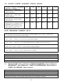
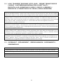
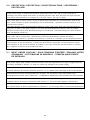
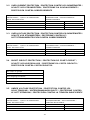
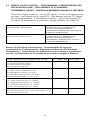
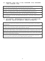
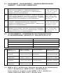
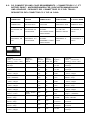
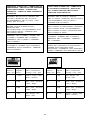
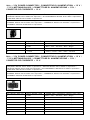
PHANTOM 500
User’s Manual
Manuel de l’utilisateur
Anwenderhandbuch
Manuale per l’operatore
Manual del usuario
The high quality of our products is assured by a continuous process of refinement
of their technical features. Therefore, it is possible that your product may differ
in some respect from the descriptions contained in this manual. This is not a
problem – it is an improvement. All features, descriptions, and illustrations
contained herein are valid as of the date of publication.
Model: PHANTOM 500
The Phantom 500 power supply includes a number of ingenious features that
allow it (under most conditions) to operate entirely silently. Its extruded
aluminum chassis acts as a massive heat sink, which dissipates heat without
the use of a fan. If the power supply's internal temperature rises above a
user-determined limit (40°, 47.5°, or 55°C), its variable-speed fan will activate,
thereby providing additional cooling. When it's running, the fan will automatically
vary its speed in response to changing temperatures. When the internal temperature
falls below this limit, the fan will shut down, allowing the power supply to operate
entirely silently.
ATX12V Version 2.0 compliant: The Phantom 500 conforms to the latest
ATX12V Version 2.0 standard. It is also backwards-compatible with previous
ATX form factor power supplies. If your motherboard has a 20-pin power
receptacle, please review Step 5 of the installation instructions carefully. The
Phantom 500 is also compatible with motherboards built to the SSI standard
and supports an 8-pin variant of the +12V connector; use it or the 4-pin +12V
connector as appropriate for your motherboard. Before you connect the power
supply to any of your devices, please consult the appropriate user manuals for
your motherboard and other peripherals.
Protection: Phantom 500 includes dual +12V output circuitry, which delivers
safer and more reliable output to your system's components. Phantom 500 also
features a variety of industrial-grade protective circuitry: OCP (over current
protection), OTP (over temperature protection), OVP (over voltage protection),
OPP (over power protection), UVP (under voltage protection), and SCP (short
circuit protection).
Chassis Ventilation Note: Before installing the Phantom 500 into your PC
chassis, please note that your chassis must be well-ventilated. Traditional
ATX power supplies include at least one fan that cools the power supply and
helps expel heat from the chassis. Even though the Phantom 500 includes a
fan, the fan will remain idle (to ensure silent operation) until the power
supply's internal temperature exceeds a user-determined limit. Therefore, you
should make sure that the exhaust fans installed in your PC chassis can cool
the whole system without the help of a power supply fan.
Transportation Note: Because of Phantom's unique construction, it is
considerably heavier than standard power supplies. To avoid possible damage
to your case, we strongly recommend removing Phantom and transporting it
separately if you plan to ship your computer somewhere or otherwise subject
it to rough handling.
2
Power Switch: This power supply includes a main power switch. Make sure
you turn the switch to the ON ( I ) position before you boot up your computer
for the first time. In normal operation there is no need to turn the switch to the
OFF ( O ) position since the power supply is equipped with a soft on/off feature
which turns your computer on and off through the soft switch on your computer
case. You may need to turn the switch to the OFF position occasionally (if your
computer crashes and you can't shut it down through use of the soft switch).
There is a blue power indicator next to the power inlet plug. When the power
supply is running, the indicator lights up.
[Applicable only to models designed for sale in the European Union: Power
supplies designed for the EU include Power Factor Correction (PFC) circuitry in
accordance with European regulation code EN61000-3-2. By altering the input
wave shape, PFC improves the power factor of the power supply and results in
increased energy efficiency, reduced heat loss, prolonged life for the power
distribution and consumption equipment, and improved output voltage stability.]
Note (not applicable to models designed for the European Union): Check the red
power supply voltage switch setting before installation. It should be the same
as your local as your local power voltage (115V for America, Canada, Japan,
etc. and 230V for Europe, some South East Asia countries, and others).
Change the voltage setting if necessary. Failure to take this precaution could
result in damage to your equipment and void your warranty.
How to set the fan operating mode
On the power supply you'll find a 3-position fan switch. This switch allows you
to set the temperature at which the power supply's fan will activate. Before
you set this switch, take a moment to think about how you usually use your
computer.
Position 1:
"High Performance" mode. The fan will activate if the temperature
reaches 40°C inside the power supply. The fan will automatically
vary its speed in response to changing temperatures. Once
the temperature decreases below 40°C, the fan will turn off. We
recommend this mode if you're a gamer or high-performance-oriented
user, and you care more about ultra-fast performance than the
noise level generated by your computer.
Position 2:
"Quiet Computing" mode. The fan will activate if the temperature
reaches 47.5°C inside the power supply. The fan will automatically
vary its speed in response to changing temperatures. Once the
temperature decreases below 47.5°C, the fan will turn off. We
recommend this mode if you'd prefer a balance between
high-performance computing and quiet computing.
3
Position 3:
"Virtually Silent" mode. The fan will activate if the temperature
reaches 55°C inside the power supply. The fan will automatically
vary its speed in response to changing temperatures. Once the
temperature decreases below 55°C, the fan will turn off. We
recommend this mode if you're determined to have the quietest
power supply possible. (Obviously, we don't recommend this
setting for overclockers or gamers.)
To install your Phantom 500, follow these steps:
1.
2.
3.
4.
5.
6.
7.
8.
Disconnect the power cord from your old power supply.
Open your computer case. Follow the directions provided in your case manual.
Disconnect all the power connectors from the motherboard and from the
peripheral devices such as case fans, hard drives, floppy drives, etc.
Remove the existing power supply from your computer case and replace it
with the Phantom power supply. Attach the Phantom to your chassis with
the screws from your original supply.
Note: Install the Phantom carefully, because the edges of the power supply
are sharp.
Connect the 24-pin Main Power Connector and the 4-pin or 8-pin +12V
connector to your motherboard as needed. If your motherboard uses a
20-pin connector, detach the 4-pin attachment on the 24-pin power
connector (see pictures 1 and 2). Connect the peripheral power connectors
to devices such as hard drives, optical drives, etc.
Picture 1
Picture 2
For 24-pin
motherboards
For 20-pin
motherboards
Set your desired fan operating mode. (See above for details.)
Close your computer case.
Connect the power cord to the Phantom 500.
4
1.0 INPUT / ENTRÉE / EINGANG / ALIMENTAZIONE IN INGRESSO / ENTRADA
1.1 VOLTAGE (AC Input) / TENSION (c.a.) / SPANNUNG (Wechselspannung) /
TENSIONE (CA in ingresso) / TENSIÓN (entrada CA)
RANGE / PLAGE /
BEREICH /
CAMPO / GAMA
MINIMUM /
MIND. / MINIMA /
MÍNIMA
NOMINAL /
NENNSP. /
NOMINALE /
NOMINAL
MAXIMUM /
MASSIMA /
MÁXIMA
UNITS / UNITÉS /
EINHEITEN /
UNITÀ /
UNIDADES
1
90
115
135
VRMS
2
180
230
265
VRMS
1.2 FREQUENCY / FRÉQUENCE / FREQUENZ / FREQUENZA / FRECUENCIA
47Hz ~ 63Hz
1.3 CURRENT / INTENSITÉ / STROMSTÄRKE / CORRENTE / CORRIENTE
115V
230V
9A
5A
1.4 INRUSH CURRENT / COURANT D'APPEL / EINSCHALTSTOSSSTROM /
CORRENTE IN AFFLUSSO / CORRIENTE DE ENTRADA
115V/60A(max.), 230V/80A (max.) at 25ºC cold start
115 V/60 A (max.), 230 V/80 A (max.) avec un démarrage à froid à 25 °C
115V/60A (max.), 230V/80A (max.) bei 25ºC Kaltstart
115V/60A (max), 230V/80A (max.) con avvio a freddo a 25ºC
115 V/60 A (máx.), 230 V/80 A (máx.) con arranque en frío a 25 °C
1.5 POWER EFFICIENCY / RENDEMENT ÉNERGÉTIQUE / LEISTUNGSGRAD /
RENDIMENTO ALIMENTAZIONE / EFICIENCIA ENERGÉTICA
Version / Versione / Versión
Efficency / Rendement énergétique / Leistungsgrad / Rendimento / Eficiencia
US / EE.UU.
86% without PFC / sans PFC / senza PFC / sin PFC
Europe / Europa
82% with PFC / avec PFC / mit PFC / con PFC
Efficiency at full load per Intel testing standard, 115V/230Vac 60/50Hz
Rendement minimum à pleine charge conforme à la norme de test d'Intel, 115V/230V c.a. 60/50Hz
Leistungsgrad bei Maximallast gemäß Intel Teststandard, 115V/230Vac 60/50Hz
Rendimento minimo a pieno carico per lo standard di prova Intel, 115V/230Vac 60/50Hz
Eficiencia mínima a plena carga según la norma de pruebas de Intel, 115V/230V CA 60/50Hz
17
2.0
OUTPUT / SORTIE / AUSGANG / USCITA / SALIDA
VOLTAGE / TENSION / SPANNUNG
TENSIONE / TENSIÓN
MAX. LOAD / CHARGE MAX. /
MAXIMALLAST / CARICO MAX. /
CARGA MÁXIMA
MIN. LOAD / CHARGE MIN. /
MINIMALLAST / CARICO MIN. /
CARGA MÍNIMA
REGULATION / RÉGULATION /
REGULIERUNG / REGOLAZIONE /
REGULACIÓN
RIPPLE & NOISE (mV) /
ONDULATION ET PARASITES (mV) /
BRUMMEN & RAUSCHEN (mV) /
ONDULAZIONE E RUMORE (mV) /
OSCILACIÓN Y RUIDO (mV)
+5V
+12V1
+12V2
+3.3V
-12V
+5Vsb
30A
17A
18A
30A
0.8A
2.0A
0.3A
0.3A
0.3A
0.3A
0A
0A
±5%
±5%
±5%
±5%
±5%
±5%
50
120
120
50
120
50
NOTE / REMARQUE / HINWEIS / NOTA
The continuous max DC output power shall not exceed 500W. +5V, +12V1, +12V2, and
+3.3V output power shall not exceed 484W
La puissance de sortie c.c. max. continue ne devra pas dépasser 500W. La puissance de sortie
+5V, +12V1, +12V2 et +3,3V ne devra pas dépasser 484W
Die kontinuierliche maximale Ausgangsleistung (Gleichstrom) darf 500W nicht überschreiten. Die
+5V, +12V1, +12V2 und +3.3V Ausgangsspannung darf 484W nicht überschreiten.
L'alimentazione in uscita CC max. continua non deve superare 500W. L'alimentazione delle
uscite +5V, +12V1, +12V2, e +3,3V non deve superare 484W
La potencia de salida CC máxima continua no debe superar los 500W. La potencia de salida de
+5V, +12V1, +12V2 y +3,3V no debe superar los 484W
Ripple & noise test condition: AC 230V/115V 50/60Hz at full load
Condition de test d'ondulation et de parasites : 230V/115V c.a., 50/60Hz, pleine charge
Testbedingungen für Brummen & Rauschen: AC 115V/230V 60/50Hz bei Maximallast
Condizione di prova: Condizione di prova di ondulazione e rumore: AC 230V/115V 50/60Hz a pieno carico
Condiciones de prueba de oscilaciones y ruido: CA de 230V/115V a 50/60Hz a plena carga
2.1 HOLD-UP TIME: 20ms (minimum) / TEMPS DE MAINTIEN : 20ms (minimum) /
VERWEILZEIT: 20ms (Minimum) / TEMPO DI INTERRUZIONE: 20ms (minimo) /
TIEMPO DE DEMORA: 20ms (mínimo)
Test Condition: 1. Full load. AC input 115V/230V, 57Hz/47Hz
Condition de test : 1. Pleine charge. Entrée c.a. 115V/230V, 57Hz/47Hz
Testbedingung: 1. Maximallast. Wechselstromeingang 115/230V, 57Hz/47Hz
Condizione di prova: 1. Pieno carico. Ingresso CA 115V/230V, 57Hz/47Hz
Condiciones de prueba: 1. Plena carga. Entrada de CA de 115V/230V a 57/47Hz
18
2.2 LOAD TRANSIENT RESPONSE (STEP LOAD) / RÉGIME TRANSITOIRE DE
CHARGE / LASTÜBERGANGSVERHALTEN (SCHRITTLAST) /
RISPOSTA ALLE VARIAZIONI DI CARICO (CARICO A GRADINO) /
RESPUESTA A TRANSITORIOS DE CARGA (CARGA REPENTINA)
Step load changes of up to 20% of full load, while other loads remains constant within the rating.
The load waveform shall be a square wave with the slope of the rise and fall at 1A/us and the frequency
shall be from 10Hz to 1 kHz. The DC output voltage will stay within regulation during the step load changes
Des changements de charge incrémentiels jusqu'à 20% de la pleine charge, tandis que les autres
charges restent constantes dans les limites des valeurs nominales. La courbe de charge devra être
une onde carrée avec la pente de montée et de descente à 1A/µs et la fréquence devra être comprise
entre 10Hz et 1kHz. La tension de sortie c.c. restera dans les limites de régulation durant les
changements de charge incrémentiels
Schrittlaständerungen von bis zu 20% bei voller Belastung, während andere Lasten innerhalb der
Nennwerte konstant bleiben. Lastwellenform: Rechteckwelle mit Neigung bei Anstieg und Abfall von
1A/us. Frequenz von 10Hz bis 1kHz. Ausgangsspannung (Gleichstrom): zwischen Schrittlaständerungen
innerhalb des Regulationsbereichs
I carichi a gradino apportano variazioni fino al 20% rispetto al pieno carico, mentre altri carichi
restano costanti entro i valori nominali. La forma d'onda del carico deve essere un'onda quadra con la
pendenza di salita e di discesa di 1A/usec e la frequenza andrà da 10Hz a 1kHz. La tensione d'uscita
CC resterà entro la regolazione durante le variazioni dei carichi a gradino
Cambios repentinos de la carga de hasta el 20% de la carga total, mientras otras cargas permanecen
constantes dentro del régimen. La onda de la carga debe tener forma cuadrada con la pendiente de
subida y bajada a 1A/us y la frecuencia debe ser de entre 10Hz y 1kHz. La tensión de salida de CC
permanecerá en lo regulado durante los cambios repentinos en la carga
2.3 OVERSHOOT / DÉPASSEMENT / ÜBERSCHWINGEN / SUPERAMENTO /
SOBREIMPULSO
Overshoot at turn on shall be less than 10% of the nominal output voltage
Le dépassement à la mise sous tension doit être inférieur à 10% de la tension de sortie nominale
Das Überschwingen beim Einschalten muss unter 10% der Nennausgangsspannung liegen
Durante l'avvio l'eccesso di correzione deve essere minore del 10% rispetto alla tensione nominale d'uscita
El sobreimpulso de encendido debe ser inferior al 10% de la tensión de salida nominal
19
3.0 PROTECTION / PROTECTION / SCHUTZSCHALTUNG / PROTEZIONE /
PROTECCIÓN
If the power supply is latched into shutdown stage (when OCP, OVP, OPP or short protection is
working), the power supply shall return to normal operation only after the fault has been removed
and should reset PS-ON for a minimum of 1 second. Then it will turn on again
Si le bloc d'alimentation est verrouillé au stade d'arrêt (en raison d'une activité du circuit de protection
OCP, OVP, OPP ou court-circuit), le bloc d'alimentation reprendra son fonctionnement normal une
fois l'erreur éliminée et après réinitialisation de PS-ON pendant 1 seconde minimum. Ensuite, il se
remettra sous tension
Wird das Netzteil in den Ausschaltstatus gebracht (wenn OCP, OVP, OPP oder Kurzschlussschutz
aktiv ist), so darf es erst dann wieder in den normalen Betriebsstatus schalten, wenn der Fehler
behoben wurde und eine PS-ON-Rücksetzung von mindestens 1 Sekunde erfolgt ist. Dann schaltet
sich das Netzteil wieder ein
Se l'alimentatore fa scattare lo spegnimento (a seguito dell'attivazione del circuito di protezione per
OCP, OVP, OPP o cortocircuito), l'alimentatore tornerà al funzionamento normale solo dopo
l'eliminazione del difetto e il ripristino di PS-ON per un minimo di 1 secondo. Poi si accenderà di nuovo
Si la fuente de alimentación se bloquea en fase de apagado (con OCP, OVP, OPP o protección contra
cortocircuitos en funcionamiento), la fuente de alimentación recuperará el funcionamiento normal
sólo después de que se haya resuelto el problema y se haya restaurado PS-ON durante un mínimo
de 1 segundo. Entonces se encenderá de nuevo
3.1 INPUT UNDER VOLTAGE / SOUS-TENSIONS D'ENTRÉE / EINGANG UNTER
SPANNUNG / SOTTENSIONE IN INGRESSO / TENSIÓN INSUFICIENTE
DE ENTRADA
The power supply shall contain protection circuitry such that application of an input voltage below the
minimum specified in Section 1.1 shall not cause any damage to the power supply
Le bloc d'alimentation devra inclure un circuit de protection de sorte que l'application d'une tension
d'entrée inférieure au minimum spécifié à la section 1.1 ne causera aucun dommage au bloc d'alimentation
Das Netzteil muss über Schutzschaltkreise verfügen, die verhindern, dass das Anlegen einer
Eingangsspannung unter dem in Abschnitt 1.1 angegebenen Mindestwert keine Schäden am Gerät anrichtet
L'alimentatore deve contenere una circuitazione di protezione tale che l'applicazione di una tensione in
ingresso minore del minimo specificato nella sezione 1.1 non possa danneggiare l'alimentatore
La fuente de alimentación debe contener circuitos de protección, para que la aplicación de una tensión
de entrada inferior al mínimo especificado en la Sección 1.1 no provoque daños a la fuente de alimentación
20
3.2 OVER CURRENT PROTECTION / PROTECTION CONTRE LES SURINTENSITÉS /
SCHUTZ VOR STROMSPITZEN / PROTEZIONE DA SOVRACORRENTI /
PROTECCIÓN CONTRA SOBRECORRIENTE
SENSE LEVEL / NIVEAU DE DÉTECTION /
ABFÜHLPEGEL / LIVELLO DI PERCEZIONE
NIVEL DE DETECCIÓN
OVER CURRENT / SURINTENSITÉ /
STROMSPITZEN / SOVRACORRENTE /
SOBRECORRIENTE
+12V1
+12V2
+5V
+3.3V
18.7A
19.5A
33.0A
30.8A
min.
min.
min.
min.
22.1A
23.4A
42.0A
39.2A
max.
max.
max.
max.
3.3 OVER VOLTAGE PROTECTION / PROTECTION CONTRE LES SURINTENSITÉS /
SCHUTZ VOR STROMSPITZEN / PROTEZIONE CONTRO LE /
SOTTOTENSIONIPROTECCIÓN CONTRA SOBRECORRIENTE
SENSE LEVEL / NIVEAU DE DÉTECTION /
ABFÜHLPEGEL / LIVELLO DI PERCEZIONE
NIVEL DE DETECCIÓN
OVER CURRENT / SURINTENSITÉ /
STROMSPITZEN / SOVRACORRENTE /
SOBRECORRIENTE
+12V1 & +12V2
+5V
+3.3V
13.3V min.
5.7V min.
3.7V min.
14.3V max.
6.2V max.
4.1V max.
3.4 SHORT CIRCUIT PROTECTION / PROTECTION DE COURT-CIRCUIT /
SCHUTZ VOR KURZSCHLUSS / PROTEZIONE DA CORTO CIRCUITO /
PROTECCIÓN CONTRA CORTOCIRCUITOS
All output to ground
Toutes les sorties à la terre
Alle Ausgänge an Masse
Tutte le uscite sono collegate alla massa a terra
Toda la salida a tierra
3.5 UNDER VOLTAGE PROTECTION / PROTECTION CONTRE LES
SOUS-TENSIONS / UNTERSPANNUNGSSCHUTZ / PROTEZIONE CONTRO
LE SOTTOTENSIONI / PROTECCIÓN CONTRA LA TENSIÓN INSUFICIENTE
SENSE LEVEL / NIVEAU DE DÉTECTION /
ABFÜHLPEGEL / LIVELLO DI PERCEZIONE
NIVEL DE DETECCIÓN
UNDER VOLTAGE / SOUS-TENSION /
UNTERSPANNUNG / SOTTOTENSIONE /
TENSIÓN INSUFICIENTE
+12V1 & +12V2
+5V
+3.3V
9.5V min.
4.1V min.
2.55V min.
21
10.5V max.
4.47V max.
2.83V max.
3.6 OVER TEMPERATURE / SURCHAUFFE / ÜBERHITZUNGSSCHUTZ /
SOVRATEMPERATURA / PROTECCIÓN CONTRA LA TEMPERATURA EXCESVA
The power supply includes an over-temperature protection sensor, which can trip and shutdown the
power supply at 100°C. Such an overheated condition is typically the result of internal current overloading
or a cooling fan failure
Le bloc d'alimentation inclut un capteur de protection anti-surchauffe, qui bascule et arrête le bloc
d'alimentation à 100°C. Un tel état de surchauffe résulte généralement d'une surcharge de courant ou
d'une panne du ventilateur de refroidissement
Das Netzteil ist mit einem Überhitzungsschutzsensor ausgestattet, der bei 100 Grad Celsius auslöst
und das Netzteil ausschaltet. Eine solche Überhitzung ist in der Regel das Ergebnis einer internen
Stromüberlastung oder eines Lüfterausfalls
L'alimentatore comprende un sensore di protezione contro la sovratemperatura, che scatta e spegne
l'alimentatore a 100°C. Una tale condizione di riscaldamento eccessivo deriva generalmente da un
sovraccarico interno di corrente o da un guasto della ventola di raffreddamento
La fuente de alimentación cuenta con un sensor de protección contra el recalentamiento, que se activa
y la apaga a 100°C. Ese estado de recalentamiento suele ser consecuencia de una sobrecarga interna
de corriente o de un fallo de los ventiladores
3.7 OVER LOAD PROTECTION / SOUS-TENSIONS D'ENTRÉE /
ÜBERLASTUNGSSCHUTZ / PROTEZIONE DA SOVRACCARICO /
PROTECCIÓN CONTRA SOBRECARGA
Overload currents to output rail will cause the output trip before they reach or exceed 110% ~ 140%
for protection, the overload currents should be ramped at a minimum rate of 10A/s starting from full load
Les courants de surcharge vers le rail de sortie entraînent le basculement de la sortie avant qu'ils
n'atteignent ou dépassent 110 à 140% à titre de protection. Les courants de surcharge doivent être
progressivement diminués au taux minimum de 10A/s, à partir d'une pleine charge
Überlastströme an der Ausgangsschiene lösen die Schutzschaltung aus, bevor 110 bis 140% erreicht
oder überschritten sind. Für die Überlastströme wird eine Flanke von mindestens 10A/s ab
Maximallast vorausgesetzt
Le correnti di sovraccarico verso la guida d'uscita faranno scattare l'uscita prima che esse
raggiungano o superino il 110% ~ 140% della protezione, le correnti di sovraccarico dovrebbero
essere scalate ad una velocità minima di 10A/s partendo dal pieno carico
Las corrientes de sobrecarga en la salida provocan como protección el corte de la salida antes de
que alcancen o superen el 110% ~ 140%; las corrientes de sobrecarga deben variar a un ritmo
mínimo de 10A/s desde la carga plena
22
4.0 TIME SEQUENCE / SÉQUENCE CHRONOLOGIQUE / ZEITLICHE ABFOLGE /
SEQUENZA DI TEMPO / SECUENCIA DE TIEMPO
T1
Power-On Time / Temps de mise sous tension / Einschaltdauer /
Tempo di accensione / Tiempo de encendido
(500ms.max.)
T2
Rise-time / Temps de montée / Anlaufzeit / Tempo di salita /
Tiempo de elevación
(20ms.max.)
T3
Power Good Delay Time / Délai de mise sous tension correcte /
Verzögerungszeit, wenn Strom OK / Ritardo di accensione / Tiempo
de retardo hasta tensión correcta
(100ms < t3 <500ms)
T4
Power Fail Delay Time / Délai de panne d'alimentation /
Verzögerungszeit, wenn Stromausfall / Ritardo per mancanza di
tensione / Tiempo de retardo hasta fallo de corriente
(1ms.min.)
T5
Hold-Up time / Temps de maintien / Verweilzeit / Tempo di
sospensione / Tiempo de retención
(17ms.min)
115V/230V(FULL LOAD): 1ms minimum
FIGURE 1
23
115V/230V (PLEINE CHARGE) : 1ms minimum
FIGURE 1
115V/230V (MAXIMALLAST): 1ms mind
ABBILDUNG 1
24
115V/230V (PIENO CARICO): 1ms minimo
FIGURA 1
115 V/230V (PLENA CARGA): 1ms mínimo
FIGURA 1
25
4.1 REMOTE ON/OFF CONTROL / TÉLÉCOMMANDE / FERNSTEUERUNG DER
EIN-/AUSSCHALTUNG / TELECOMANDO DI ACCENSIONE /
SPEGNIMENTO (ON/OFF) / CONTROL DE ENCENDIDO/APAGADO A DISTANCIA
The power supply is turn on / off by TTL signal / Le bloc d'alimentation est
mis sous / hors tension par un signal TTL / Das Netzteil wird per TTL-Signal
ein-und ausgeschaltet / L'alimentatore è acceso / spento dal segnale TTL /
La fuente de alimentación se enciende y apaga mediante una señal TTL
ACTIVE LOW / ACTIVÉ BAS / AKTIV NIEDRIG /
ATTIVO BASSO / BAJA ACTIVA
POWER SUPPLY TURN ON / MISE SOUS
TENSION DU BLOC D'ALIMENTATION /
NETZTEIL WIRD EINGESCHALTET /
ACCENSIONE ALIMENTATORE / ENCIENDE LA
FUENTE DE ALIMENTACIÓN
ACTIVE HIGH / ACTIVÉ HAUT / AKTIV HOCH /
ATTIVO ALTO / ALTA ACTIVA
POWER SUPPLY TURN OFF / MISE HORS
TENSION DU BLOC D'ALIMENTATION /
NETZTEIL WIRD AUSGESCHALTET /
SPEGNIMENTO ALIMENTATORE / APAGA LA
FUENTE DE ALIMENTACIÓN
Remote On/Off Signal Characteristics / Caractéristiques du signal de
marche/arrêt de la télécommande / Signaleigenschaften der Ein-/AusschaltFernsteuerung / Caratteristiche del segnale remoto di accensione /spegnimento
(on/off) / Características de las señales de encendido y apagado a distancia
PS-ON / MARCHE- BLOC D'ALIMENTATION / ÍPS-ON
Vil input low voltage / Basse tension d'entrée Vil /
Vil (Eingangsspannung niedrig) /
Vil, bassa tensione in ingresso /
Tensión baja de entrada VIL
Lil, input low current ,Vin=0.4V /
Lil, faible courant d'entrée,Vin=0,4V /
Lil (Eingangsstrom niedrig), Vin=0,4V /
Lil, inserimento bassa corrente VIN=0,4V /
Corriente baja de entrada LIL, Vin=0,4V
Vih, input High voltage, lin=-200uA /
Vih, haute tension d'entrée, lin=-200uA /
Vih (Eingangsspannung hoch), lin=-200uA /
Vih, inserimento alta tensione, lin=-200uA /
Tensión alta de entrada VIH, lin=-200uA
Vih open circuit, lin=0 / Vih, circuit ouvert, lin=0 /
Vih (Stromkreis offen), lin=0 / Vih, circuito aperto, lin=0 /
Circuito abierto VIH, lin=0
26
MIN / MIND / MÍN.
MAX / MÁX.
0.8V
-1.6mA
2.0V
5.25V
4.2 AUXILIARY +5Vsb / AUX (+5 Vsb) / AUXILIAIRE +5Vsb / AUSILIARIO
+5Vsb / AUXILIAR +5Vsb
This power supply is specifically equipped with an independent stand-by +5V output current, 2.0A
max. This output will always provide +5V except when the AC line is cut-off
Ce bloc d'alimentation est spécialement équipé d'un courant de sortie +5V d'attente indépendant de
2,0A max. Cette sortie fournit toujours +5V, sauf lorsque la ligne secteur est coupée
Dieses Netzteil bietet einen unabhängigen Bereitschaftsausgangsstrom (+5V, 2,0A max.), der
dauerhaft +5V Spannung bietet, außer wenn der Wechselstromzugang unterbrochen ist
Questo alimentatore è dotato specificamente di una corrente di uscita indipendente di riserva a
+5V, 2,0A max. Questa uscita fornirà sempre +5V tranne quando la linea CA è isolata
Esta fuente de alimentación está equipada específicamente con una corriente de salida de reserva de
+5V independiente, de 2A máx. Esta salida siempre proporciona +5V excepto cuando la línea de
CA está cortada
4.3 AUTO RESTART / REDÉMARRAGE AUTOMATIQUE / AUTOMATISCHER
NEUSTART / RIAVVIO AUTOMATICO / REINICIO AUTOMÁTICO
If the power supply's output drops out of regulation, caused by AC line Voltage, the power supply
will automatically resume normal operation only after the AC line voltage returns to the specified
operating range
Si la sortie du bloc d'alimentation ne se situe plus dans les limites de régulation (cause : tension
secteur), le bloc d'alimentation reprendra automatiquement son fonctionnement normal une fois que
la tension secteur sera revenue dans la plage d'exploitation spécifiée
Wenn die Ausgangsleistung des Netzteils aufgrund der Spannung der Wechselstromleitung den
Toleranzbereich überschreitetet, schaltet das Netzteil erst dann wieder automatisch in den normalen
Betrieb zurück, wenn die Spannung der Wechselstromleitung wieder im spezifizierten Bereich liegt
Se l'uscita dell'alimentatore è senza tensione a causa della regolazione della tensione di linea CA,
l'alimentatore riprende automaticamente il normale funzionamento soltanto dopo il ripristino della tensione
CA al livello di funzionamento specificato
Si la salida de la fuente de alimentación cae por debajo de lo regulado a causa de la tensión de la
línea de CA, la fuente de alimentación reanuda automáticamente su funcionamiento normal sólo
cuando la tensión de la línea de CA vuelve al régimen operativo especificado
27
5.0 ENVIRONMENT / ENVIRONNEMENT / UMGEBUNGSBEDINGUNGEN /
AMBIENTE / CONDICIONES AMBIENTALES
5.1 AMBIENT OPERATION TEMPERATURE / TEMPÉRATURE
D'EXPLOITATION AMBIANTE / UMGEBUNGSTEMPERATUR
(BETRIEB) / TEMPERATURA AMBIENTALE DI FUNZIONAMENTO /
TEMPERATURA DE FUNCIONAMIENTO
0ºC to +50ºC / 0 à
+50ºC / 0ºC bis +50
ºC / da 0ºC a +50°C /
De 0°C a +50°C
5.2 AMBIENT OPERATION RELATIVE HUMIDITY / HUMIDITÉ RELATIVE
D'EXPLOITATION AMBIANTE / RELATIVE LUFTFEUCHTE (BETRIEB) /
UMIDITÀ AMBIENTALE RELATIVA DI FUNZIONAMENTO / HUMEDAD
AMBIENTAL RELATIVA AMBIENTAL DE FUNCIONAMIENTO
20% to 85% / 20 à
85% / 20% bis 85% /
dal 20% all'85% / De
20% a 85%
5.3 AMBIENT STORAGE TEMPERATURE / TEMPÉRATURE AMBIANTE DE
STOCKAGE / UMGEBUNGSTEMPERATUR (LAGERUNG) /
TEMPERATURA AMBIENTALE DI CONSERVAZIONE / TEMPERATURA
AMBIENTAL DE ALMACENAMIENTO
-40ºC to +70ºC / -40 à
+70 ºC / -40°C bis+70°C
/ da -40°C a+70°C /
De -40°C a +70°C
5.4 AMBIENT STORAGE RELATIVE HUMIDITY / HUMIDITÉ RELATIVE
AMBIANTE DE STOCKAGE / RELATIVE LUFTFEUCHTE (LAGERUNG) /
UMIDITÀ AMBIENTALE RELATIVA DI CONSERVAZIONE / HUMEDAD
AMBIENTAL RELATIVA DE ALMACENAMIENTO
10% to 95% / 10 à
95% / 10% bis 95% /
dal 10% al 95% / De
10% a 95%
6.0 CE REQUIREMENTS / INTERFÉRENCES ÉLECTROMAGNÉTIQUES /
CE ANFORDERUNGEN / REQUISITI CE / REQUISITOS DE LA CE
6.1
EMI REQUIREMENTS
Meets FCC PART15 CLASS B
INTERFÉRENCES ÉLECTROMAGNÉTIQUES
Conforme à FCC partie 15 classe B
CE ANFORDERUNGEN
Entspricht FCC TEIL 15 KLASSE B
REQUISITI EMI
Soddisfa i requisiti FCC PARTE 15 CLASSE B FCC
REQUISITOS EMI
Cumple FCC, Apartado 15, Clase B
6.2 SAFETY
REQUIREMENTS
Meets UL 609501:2003, First Edition
Meets EN 60950-1
Meets IEC 60950:1999,
Third Edition
EXIGENCES DE
SÉCURITÉ
Conforme à UL 60950- Conforme à
1:2003, Première édition EN 60950-1
Conforme à IEC
60950:1999, 3ème édition
SICHERHEITSBESTIMMUNGEN
Entspricht UL 609501:2003, 1. Edition
Entspricht EN 60950-1
Entspricht IEC
60950:1999, 3. Edition
REQUISITI DI
SICUREZZA
Soddisfa 609501:2003, Prima edizione
Soddisfa i requisiti
della EN 60950-1
Soddisfa IEC
60950:1999, Terza edizione
REQUISITOS DE
SEGURIDAD
Cumple UL 60950Cumple EN60950-1
1:2003, Primera edición
Cumple CEI
60950:1999, Tercera edición
7.0 MTBF at 25°C=80,000 hours / Moyenne des temps de bon fonctionnement
à 25°C=80 000 heures / MTBF bei 25°C=80.000 Stunden /
Tempo medio tra un guasto e l’altro (MTBF) a 25°C=80.000 ore /
Tiempo medio entre fallos a 25°C=80.000 horas
28
8.0 DC CONNECTOR AND CASE REQUIREMENTS / CONNECTEURS C.C. ET
BOÎTIER EXIGÉ / ANFORDERUNGEN FÜR GLEICHSTROMANSCHLUSS
UND GEHÄUSE / REQUISITI DEL CONNETTORE CC E DEL TELAIO /
REQUISITOS DEL CONECTOR CC Y DE LA CAJA
8.1 BASEBOARD
CONNECTOR
CONNECTEUR DE
PLINTHE
GRUNDPLATTENANSCHLUSS
CONNETTORE
SCHEDA BASE
CONECTOR DE
LA PLACA BASE
ATX MAIN
CONNECTOR
CONNECTEUR
SECTEUR ATX
ATX HAUPTANSCHLUSS
CONNETTORE
PRINCIPALE ATX
CONECTOR
PRINCIPAL ATX
HOUSING: P/N
P20-I42002 OR
EQU
BOÎTIER: RÉF.
P20-I42002 OU
ÉQUIVALENT
GEHÄUSE:
TEILENR.
P20-I42002 ODER
ÄQUIVALENT
ALLOGGIAMENTO: P/N P20I42002 O EQUIV
CARCASA: Nº R
P20-I42002 O
EQUIV
TERMINAL: P/N
I42002BS-2 OR
EQU
BORNE : RÉF.
I42002BS-2 OU
ÉQUIVALENT
KLEMME:
TEILENR.
I42002BS-2 ODER
ÄQUIVALENT
TERMINALE: P/N
I42002BS-2 O
EQUIV
TERMINAL: Nº
R I42002BS-2 O
EQUIV
16AWG
(Wire / Conducteur /
Leitung / cavo / hilo)
Orange / Arancione /
Naranja
Blue / Bleu / Blau / Blu
/ Azul
Black / Noir / Schwarz
/ Nero / Negro
Green / Vert / Verde /
Grün (22AWG)
Black / Noir / Schwarz
/ Nero / Negro
Signal /
Segnale /
Señal
+3.3V
Black / Noir / Schwarz
COM
/ Nero / Negro
Empty / Vide / Leer /
Vuoto / Vacío
Red / Rouge / Rot /
Rosso / Rojo
Red / Rouge / Rot /
Rosso / Rojo
Red / Rouge / Rot /
/ Nero / Negro
13
1
+3.3V
14
2
+3.3V
15
3
COM
16
4
+5V
17
5
COM
18
6
+5V
19
7
COM
20
8
POK
21
9
+5VSB
22
10
+12V1V
23
11
+12V1V
24
12
+3.3V
COM
PS-ON
COM
Empty / Vide /
Leer / Vuoto /
Vacío
+5V
+5V
+5V
COM
16AWG
(Wire / Conducteur /
Leitung / cavo / hilo)
Orange / Arancione /
Naranja
Orange / Arancione /
Naranjal
Black / Noir / Schwarz
/ Nero / Negro
Red / Rouge / Rot /
Rosso / Rojo
Black / Noir / Schwarz
COM
Rosso / Rojo
Black / Noir / Schwarz
Signal /
Pin /
Broche / Segnale /
Stift / Clv Señal
-12V
/ Nero / Negro
Black / Noir / Schwarz
Pin /
Broche /
Stift / Clv
29
/ Nero / Negro
Red / Rouge / Rot /
Rosso / Rojo
Black / Noir / Schwarz
/ Nero / Negro
Gray / Gris / Grau /
Grigio / (22AWG)
Purple / Violet / Lila /
Viola / Morado
Yellow / Jaune / Gelb /
Amarillo
Yellow / Jaune / Gelb /
Amarillo
Orange / Arancione /
Naranja
PERIPHERAL CONNECTOR / CONNECTEUR DE
PÉRIPHÉRIQUE / ANSCHLUSS FÜR PERIPHERIE
DISKETTENLAUFWERK / CONNETTORE
PERIFERICO / CONECTOR PARA PERIFÉRICOS
DISQUETES
FLOPPY DRIVE CONNECTOR / CONNECTEUR
DE LECTEUR DE DISQUETTE / ANSCHLUSS
FÜR / CONNETTORE PER UNITÀ FLOPPY /
CONECTOR PARA UNIDAD DE
HOUSING: JMT JP1120-4 / BOÎTIER: JMT
JP1120-4 / GEHÄUSE: JMT JP1120-4 /
ALLOGGIAMENTO: JMT JP1120-4 / CARCASA: JMT JP1120-4
HOUSING: JMT JP11635-4 / BOÎTIER:
JMT JP11635-4 / GEHÄUSE: JMT JP11635-4
/ ALLOGGIAMENTO: JMT JP11635-4 /
CARCASA: JMT JP11635-4
HOUSING: WST P4-A10202 OR EQU /
BOÎTIER: WST P4-A10202 OR EQU /
GEHÄUSE: WST
P4-A10202 ODER / ALLOGGIAMENTO: WST
P4-A10202 O EQUIV / CARCASA: WST
P4-A10202 O EQUIV
HOUSING: WST
WST P4-I25001
WST P4-I25001
WST P4-I25001
WST P4-I25001
TERMINAL: JMT J1120BS-2 / BORNE: JMT
J1120BS-2 / KLEMME: JMT J1120BS-2 /
TERMINALE: JMT J1120BS-2 / TERMINAL:
JMT J1120BS-2
TERMINAL: JMT J11635BS-2 / BORNE: JMT
J11635BS-2 / KLEMME: JMT J11635BS-2 /
TERMINALE: JMT J11635BS-2 / TERMINAL:
JMT J11635BS-2
TERMINAL: WST A10209BS-2 / BORNE: WST
A10209BS-2 / KLEMME: WST A10209BS-2 /
TERMINALE: WST A10209BS-2 / TERMINAL:
WST A10209BS-2
TERMINAL: WST I25001BS-2 OR EQU /
BORNE: WST I25001BS-2 OU ÉQUIVALENT /
KLEMME: WST I25001BS-2 ODER
ÄQUIVALENT / TERMINALE: WST I25001BS-2
O EQUIV / TERMINAL: WST I25001BS-2 O EQUIV
Pin /
Broche /
Stift / Clv
Signal /
Segnale /
Señal
18AWG
(Wire / Conducteur /
Leitung / cavo / hilo)
Pin /
Broche /
Stift / Clv
Signal /
Segnale /
Señal
22AWG
(Wire / Conducteur /
Leitung / cavo / hilo)
1
+12V1
Yellow / Jaune / Gelb
Giallo / Amarillo
1
+5V
Red / Rouge / Rot /
Black / Noir / Schwarz
2
2
COM
P4-I25001 OR EQU / BOÎTIER:
OU ÉQUIVALENT / GEHÄUSE:
ODER / ALLOGGIAMENTO:
O EQUIV / EQUIVCARCASA:
O EQUIV
Rosso / Rojo
COM
/ Nero / Negro
3
COM
/ Nero / Negro
Black / Noir / Schwarz
3
COM
/ Nero / Negro
4
+5V
Black / Noir / Schwarz
Black / Noir / Schwarz
/ Nero / Negro
Red / Rouge / Rot /
4
Rosso / Rojo
30
+12V1
Yellow / Jaune / Gelb
Giallo / Amarillo
4pin +12V POWER CONNECTOR / CONNECTEUR D’ALIMENTATION +12 V /
+12-V-NETZANSCHLUSS / CONNETTORE DI ALIMENTAZIONE +12V /
CONECTOR DE CORRIENTE +12 V
HOUSING: MOLEX 39-01-2040 or equivalent / BOÎTIER: MOLEX 39-01-2040 ou équivalent /
GEHÄUSE: MOLEX 39-01-2040 oder Äquivalent / ALLOGGIAMENTO: MOLEX 39-01-2040 o equivalente /
CARCASA: MOLEX 39-01-2040 o equivalente
TERMINAL: MOLEX 39-29-9042 or equivalent / BORNE: MOLEX 39-29-9042 ou équivalent /
KLEMME: MOLEX 39-29-9042 oder Äquivalent / TERMINALE: MOLEX 39-29-9042 o equivalente /
TERMINAL: MOLEX 39-29-9042 o equivalente
Pin / Broche / Stift / Clv
1
Signal / Segnale / Señal
COM
18AWG (Wire / Conducteur / Leitung / cavo / hilo)
2
COM
Black / Noir / Schwarz / Nero / Negro
3
+12V2
Yellow / Jaune / Gelb / Giallo / Amarillo
4
+12V2
Yellow / Jaune / Gelb / Giallo / Amarillo
Black / Noir / Schwarz / Nero / Negro
8pin +12V POWER CONNECTOR / CONNECTEUR D’ALIMENTATION +12 V /
+12-V-NETZANSCHLUSS / CONNETTORE DI ALIMENTAZIONE +12V /
CONECTOR DE CORRIENTE +12 V
HOUSING: MOLEX 39-01-2040 or equivalent / BOÎTIER: MOLEX 39-01-2040 ou équivalent /
GEHÄUSE: MOLEX 39-01-2040 oder Äquivalent / ALLOGGIAMENTO: MOLEX 39-01-2040 o equivalente /
CARCASA: MOLEX 39-01-2040 o equivalente
TERMINAL: MOLEX 39-29-9042 or equivalent / BORNE: MOLEX 39-29-9042 ou équivalent /
KLEMME: MOLEX 39-29-9042 oder Äquivalent / TERMINALE: MOLEX 39-29-9042 o equivalente /
TERMINAL: MOLEX 39-29-9042 o equivalente
Pin / Broche / Stift / Clv
1
Signal / Segnale / Señal
COM
18AWG (Wire / Conducteur / Leitung / cavo / hilo)
2
COM
Black / Noir / Schwarz / Nero / Negro
3
COM
Black / Noir / Schwarz / Nero / Negro
4
COM
Black / Noir / Schwarz / Nero / Negro
5
+12V2
Yellow / Jaune / Gelb / Giallo / Amarillo
6
+12V2
Yellow / Jaune / Gelb / Giallo / Amarillo
7
+12V2
Yellow / Jaune / Gelb / Giallo / Amarillo
8
+12V2
Yellow / Jaune / Gelb / Giallo / Amarillo
Black / Noir / Schwarz / Nero / Negro
31
SERIAL ATA POWER CONNECTOR / CONNECTEUR D’ALIMENTATION ATA SÉRIE /
SATA-NETZANSCHLUSS / CONNETTORE DI ALIMENTAZIONE SERIAL ATA /
CONECTOR DE CORRIENTE SERIAL ATA
HOUSING: MOLEX 675820000 OR EQU / BOÎTIER: MOLEX 675820000 OU ÉQUIVALENT /
GEHÄUSE: MOLEX 675820000 ODER ÄQUIVALENT / ALLOGGIAMENTO: MOLEX 675820000 O
EQUIV / CARCASA: MOLEX 675820000 O EQUIV
TERMINAL: MOLEX 67581000 OR EQU / BORNE: MOLEX 67581000 OU ÉQUIVALENT /
KLEMME: MOLEX 67581000 ODER ÄQUIVALENT / TERMINALE: MOLEX 67581000 O EQUIV /
TERMINAL: MOLEX 67581000 O EQUIV
Pin / Broche / Stift / Clv
Signal / Segnale / Señal
18AWG (Wire / Conducteur / Leitung / cavo / hilo)
1
+12V1
Yellow / Jaune / Gelb / Giallo / Amarillo
2
COM
Black / Noir / Schwarz / Nero / Negro
3
+5V
Red / Rouge / Rot / Rosso / Rojo
4
COM
Black / Noir / Schwarz / Nero / Negro
5
+3.3V
Orange / Arancione / Naranja
PCI EXPRESS CONNECTOR / CONNECTEUR PCI EXPRESS / PCI
EXPRESS-ANSCHLUSS / CONNETTORE PCI EXPRESS / CONECTOR DE PCI EXPRESS
HOUSING: MOLEX 455590002 OR EQU / BOÎTIER: MOLEX 455590002 OU ÉQUIVALENT /
GEHÄUSE: MOLEX 455590002 ODER ÄQUIVALENT / ALLOGGIAMENTO: MOLEX 455590002 0
EQUIV / CARCASA: MOLEX 455590002 O EQUIV
TERMINAL: MOLEX 455580002 OR EQU / BORNE: MOLEX 455580002 OU ÉQUIVALENT /
KLEMME: MOLEX 455580002 ODER ÄQUIVALENT / TERMINALE: MOLEX 455580002 0 EQUIV /
TERMINAL: MOLEX 455580002 O EQUIV
Pin / Broche / Stift / Clv
Signal / Segnale / Señal
18AWG (Wire / Conducteur / Leitung / cavo / hilo)
1
+12V1
Yellow / Jaune / Gelb / Giallo / Amarillo
2
+12V1
Yellow / Jaune / Gelb / Giallo / Amarillo
3
+12V1
Yellow / Jaune / Gelb / Giallo / Amarillo
4
COM
Black / Noir / Schwarz / Nero / Negro
5
COM
Black / Noir / Schwarz / Nero / Negro
6
COM
Black / Noir / Schwarz / Nero / Negro
32
Antec, Inc.
47900 Fremont Blvd.
Fremont, CA 94538
Tel: 1-510-770-1200
Fax: 1-510-770-1288
Antec Europe B.V.
Sydneystraat 33
3047 BP Rotterdam
The Netherlands
Tel: +31 (0) 10 462-2060
Fax: +31 (0) 10 437-1752
Technical Support
US & Canada
1-800-22ANTEC
[email protected]
Europe
+31 (0) 10 462-2060
[email protected]
www.antec.com
© Copyright 2005 Antec, Inc. All rights reserved. All trademarks are the property of their respective owners.
Reproduction in whole or in part without written permission is prohibited. Printed in China.
Version 1.0.5 1/28/2005