1
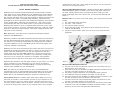
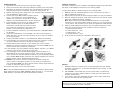
NEOPOWER 380/480
User’s Manual
Manuel de l’utilisateur
Anwenderhandbuch
Manuale per l’operatore
Manual del usuario
ATX12V v2.0 Power Supply
Includes Universal Input and Active Power Factor Correction (PFC)
crashes and you can't shut it down using the soft switch, you can switch the
main power to the OFF (O) position.
Models: NEO380 and NEO480
Advanced Cable Management System – NeoPower features Antec's advanced
Cable Management System. It allows you to use only the power cables that
you need, thereby reducing clutter and improving airflow inside your case.
Inside the package, apart from a power cord, you will find the following (see
Photo 1):
NeoPower power supplies include Universal Input and Active PFC. Universal
Input allows you to connect NeoPower to any standard power circuit between
100~240V, without having to worry about setting a voltage switch. Active
PFC improves the power factor of the power supply by altering the input current
wave shape. This results in increased energy efficiency, reduced heat loss,
prolonged life for power distribution and consumption equipment, and improved
output voltage stability. NeoPower also includes dual +12V output circuitry,
which delivers safer and more reliable output to your system's components.
NeoPower also features a variety of industrial-grade protective circuitry: OCP
(over current protection), OTP (over temperature protection), OVP (over voltage
protection), OPP (over power protection), UVP (under voltage protection) and
SCP (short circuit protection).
Note: NeoPower's active PFC circuitry complies with European standard
regulation code EN61000-3-2.
NeoPower unit. On the front of the power supply, you'll find some wires. These
include:
1. The 24-pin Main Power Connector
2. The 4-pin +12V connector
3. The 3-pin fan signal connector
4. A 2-pin Fan Only socket, which should only be used with the Fan Only
cable set (see #6 below)
5. Four 6-pin output sockets, which you can use for your drives and other
peripherals
NeoPower includes an advanced temperature-response system that provides an
optimum balance between noise reduction and cooling. The power supply fan
will always run at the lowest speed possible for existing load and conditions.
The result? NeoPower will run considerably quieter than power supplies with
traditional thermally-controlled fans.
NeoPower can also control the speed of your system case fans. You'll find two
dedicated fan connectors (marked "Fan Only") to which you can connect your
system case fans. NeoPower's circuitry will then regulate your case fans,
further reducing system noise. Note: Please don't connect more than three
external fans to the "Fan Only" connectors. If you need more cooling power
than that, you can connect your case fans to the regular 4-pin peripheral
connectors. But that setup won't be as quiet as our recommended setup.
NeoPower also includes a 3-pin fan signal connector. If you connect it to one of
the fan connectors on your motherboard, you can monitor the speed of
NeoPower's fan through your motherboard BIOS or through the monitoring
software that's included with your motherboard.
Note: The speed of the 120mm fan may be as low as 1000 RPM when
temperatures are low. At these speeds some motherboards may not be able to
properly detect the fan speed and may generate false warning of fan failure.
Please refer to your motherboard manual for proper fan monitoring set up.
Power Switch: NeoPower includes a main power switch. Make sure you turn
the switch to the ON ( I ) position before you boot up your computer for the
first time. Normally, you won't need to switch to the OFF (O) position, since
the power supply includes a soft on/off feature. This lets you turn your computer
on and off by using the soft switch on your computer case. If your computer
1
Photo 1
Advanced Cable Management Wire Set.
6. One set of wires with two Fan-Only connectors at one end and one 2-pin
PSU connector at the other end
7. Three sets of wires with standard 4-pin Molex peripheral connectors at one
end and a 6-pin PSU connector at the other end
8. One 24-pin to 20-pin adapter for the motherboard power connector
9. Four additional connectors, 2 Molex & 2 SATA, for optional use
10. One set of wires with one standard 4-pin Molex peripheral connector at one
end and two Floppy power connectors at the other end
11. One set of wires with a 6-pin PCI Express graphic card connector at one
end and a 6-pin PSU connector at the other end
12. One set of wires with SATA drive connectors at one end and a 6-pin PSU
connector at the other end. Note: The SATA connectors include a +3.3V
output so you can power next-generation SATA devices.
2
Installing NeoPower
1. Disconnect the power cord from your old power supply.
2. Open your computer case. Follow the directions provided in your case manual.
3. Disconnect all the power connectors from the motherboard and from the
peripheral devices such as case fans, hard drives, floppy drives, etc.
4. Remove the existing power supply from your computer case and replace it
with the NeoPower power supply.
5. Connect the 24-pin Main Power Connector and the
4-pin +12V Connector to your motherboard as
needed. You will need to use the 24-pin to 20-pin
adapter if your motherboard uses a 20-pin connection.
6. In the package, you'll find a set of power supply-toMolex connectors. (One of the PSU to Molex
connectors is shorter than the others.) Connect
Photo 2
one of the 6-pin connectors to any of the 6-pin
sockets on the power supply. (See Photo 2.)
7. Connect the Molex connector to your hard disk drives or CD-ROM. Repeat
as necessary.
8. If you have a SATA drive: In the package, you'll find a power supply-toSATA connector. Connect the 6-pin connector to any of the 6-pin sockets
on the power supply.
9. Connect the SATA connector to your SATA drive. Repeat as necessary.
10. In the package, you'll find a power supply-to-Fan Only connector. Connect
the 2-pin connector to the 2-pin socket on the power supply.
11. Connect the Fan-Only connector to your system fans. This will allow
NeoPower to control the speed of the fans you've connected. Note: Do not
connect the Fan-Only connectors to CPU fans.
12. In the package, you'll find a Molex-to-Floppy adapter. Connect it to a Molex
connector, and connect a floppy drive if you wish.
13. In the package, you'll find a PCI Express graphic card connector. It is
identifiable as the only 6-pin connector with 3 yellow wires and 3 black
wires. Connect the 6-pin PCI Express connector to your PCI Express graphic
card if needed. Note: Please consult the user manual supplied with your PCI
Express graphic card for detailed usage instructions.
14. Optional: If you'd like to monitor the speed of the power supply fan,
connect the 3-pin fan signal connector to one of the fan connectors on
your motherboard. Note: You don't need to connect the fan signal connector
in order for the power supply to work.
15. Connect the power cord to the power supply.
Note: If your motherboard requires a 6-pin AUX Power Connector, please contact
Antec Customer Service at (888) 54ANTEC (North America) or +31 (10) 4622060 (Europe) to purchase the optional AUX Power Connector.
Additional Connectors
The spare connectors are not intended to add additional length to the cable sets,
but rather to add additional connectors to the existing cables.
To add a spare Molex or SATA connector to an existing cable:
1. Measure and mark the desired position on the wire set that you want to
add the additional connector to.
2. Remove the wire set from the power supply and place it on a flat, firm surface.
3. Place the additional connector under the wires with the cap open as shown.
See Photo 3 (Molex) and Photo 4 (SATA).
Note: When connecting an additional SATA Connector, we recommend
connecting it to the existing SATA wires (5 wires) so it can incorporate the
+3.3V output. This will allow you to power next-generation SATA devices.
4. With one hand holding the connector, use a flat head screwdriver to push
wires into the proper notch on the connector as shown in Photo 5.
a) Black Wires are Ground
b) Yellow Wires are +12V
c) Red Wires are +5V
d) Orange Wires are +3.3V
5. Close the cap to complete the installation. (See Photo 6.)
Photo 3
Photo 4
Photo 5
Photo 6
Photo 7
Photo 8
Warning:
1. Please be careful! A connector with incorrectly-aligned wires will damage
the device connected to it. It could also damage the power supply, or even
your entire system.
2. We STRONGLY recommend that you use a multi-meter to measure the
voltage from the newly added connector to make sure it has been done
correctly. (See Photo 7.)
3. If you need to remove an additional connector from a cable, please wrap
the wire with electrical tape. (See Photo 8.)
Disclaimer: The additional connectors are provided for your convenience.
Antec will not be responsible for any damage due to the incorrect connection
of the additional Molex or SATA connectors.
3
4
Quantity
1
Description
Part name
includes 24-pin main connector,
4-pin 12V connector, and 3-pin fan
monitoring connector with cable
installed
NEO power supply
1
Molex connector w/ 47 cm cable
includes three Molex connectors
2
Molex connector w/ 77 cm cable
includes three Molex connectors
1
77 cm Serial ATA connector w/cable
includes two Serial ATA connectors
1
40 cm Fan-Only Connector w/cable
includes two Fan-only connectors
1
14 cm Molex to Floppy connectors
w/cable
includes one Molex and two floppy
connectors
2
Spare Molex connector
4-pin periperal Molex connector
2
Spare Serial ATA connector
15-pin Serial ATA connector
1
10 cm 24pin-to-20pin adapter
24-pin to 20-pin adapter
1
60 cm PCI Express adapter
includes one PCI Express connector
1
Optional Aux connector
w/ 48 cm cables*
includes one optional aux connector
*Optional Aux Power Connector w/cables (48 cm long) is available through
Antec customer service. Call for availability.
1.0 INPUT:
1.1 VOLTAGE
Range: AC Input 100V-240V ±10%
1.6 POWER EFFICIENCY
70% (min.) at full and typical loads, 115V/230Vac 60/50Hz
60% (min.) at light load
2.0 OUTPUT:
VOLTAGE
+5V
+12V1 +12V2 +3.3V
-12V
NEO380
35A
16A
13A
28A
1.0A
2.0A
NEO480
38A
18A
15A
30A
1.0A
2.0A
0.3A
0.4A
0.4A
0.3A
0A
0A
±3%
±3%
±3%
±3%
±5%
±5%
120
120
MIN. LOAD
REGULATION
RIPPLE& NOISE (mV)
50
50
120
Total Max. Output
+5V, +12V & +3.3V max. Output
NEO380
380W
360W
NEO480
480W
460W
2.
3.
4.
Ripple & noise test condition: AC 230V/115V 50/60Hz full load
Peak power and current loading shall be supported for a minimum of 1 second.
12V combined current.
1.2 FREQUENCY
47HZ ~ 63HZ
12V1 + 12V2
26A
NEO480
32A
1.3 CURRENT
5.
NEO380
6A
NEO480
8A
2.1 HOLD-UP TIME:
20msec (min.) at full load. AC input 115V/230V, 57Hz/47Hz
POWER FACTOR VALUE
0.90 (min.)
1.5
INRUSH CURRENT
115V(max)
230V(max)
NEO380
40A
80A
NEO480
60A
100A
50
NOTE:
1. The continuous max. DC output power
NEO380
1.4
+5Vsb
MAX. LOAD
Peak +12 V1 current shall be supported for a minimum of 0.5 seconds.
2.2 LOAD TRANSIENT RESPONSE (STEP LOAD)
Step load changes of up to 20% of full load, while other loads remains constant
within the rating. The load waveform shall be a square wave with the slope of
the rise and fall at 1A/µsec and the frequency shall be from 10Hz to 1 kHz. The
DC output voltage will stay within regulation during the step load changes.
2.3 OVERSHOOT
During power supply start-up, the output voltages shall be less than 10% of the
nominal output voltage. Example, the +5V shall not exceed +5.5V.
3.0 PROTECTION:
If the power supply is latched into shutdown stage due to protection circuit
activity, the power supply shall return to normal operation only after the fault
at 25°C cold start
5
6
has been removed and reset PS-ON for a minimum of 1 second. Then it will
turn on again.
115V/230V(FULL LOAD):1mS minimum
3.1 OVER CURRENT PROTECTION
+5V
Over current (Sense level)
+12V1 &+12V2
AC-V
+3.3V
NEO380
40A Min.
52A Max. 19A Min.
26A Max. 34A Min. 45A Max.
NEO480
44A Min.
56A Max. 24A Min.
26A max. 36A Min. 47A Max.
AC-O N
AC-O FF
3.2 OVER VOLTAGE PROTECTION
Sense level
+12V1&+12V2
H IGH
Over Voltage
13.3V Min.
H
IGH
PS-O N
LO W
VB =4.75V
14.3V Max.
+5V
5.7V Min.
6.2V Max.
+3.3V
3.7V Min.
4.1V Max.
+5V WAVE FO RM
T2
P.G WAVE FORM
T1
3.3 SHORT CIRCUIT PROTECTION
Short circuit protection is used to protect the components and the power supply,
if a short circuit happens on a component the current goes to ground.
TURN-ON
T3
T4
ON
-RING
PO W ER FAIL
PO W ER GO O D
T5 HOL D-UP TIM E
FIGURE 1
3.4 UNDER VOLTAGE PROTECTION
Sense level
+12V1&+12V2
9.5V Min.
10.5V Max.
4.1 REMOTE ON/OFF CONTROL
The power supply is turned on/off by TTL signal.
+5V
4.1V Min.
4.47V Max.
2.55V Min.
2.83V Max.
Active Low
Power Supply turn on
Active High
Power Supply turn off
+3.3V
Under Voltage
3.5 OVER TEMPERATURE
The power supply includes an over-temperature protection sensor, which can
trip and shutdown the power supply at 100°C. Such an overheated condition is
typically the result of internal current overloading or a cooling fan failure.
3.6 OVER LOAD PROTECTION
Overload currents to output rail will cause the output trip before they reach or
exceed 110% ~ 160% for protection, the overload currents should be ramped
at a minimum rate of 10 A/s starting from full load.
4.0 TIME SEQUENCE:
T1
Power-On Time (500msec. max.)
T2
Rise-time (20msec. max.)
T3
Power Good Delay Time (100msec. < t3 <500msec.)
T4
Power Fail Delay Time (1msec. min.)
T5
Hold-Up time (20msec. min.)
Remote On/Off Signal Characteristics
PS-ON
MIN
MAX
Vil input low voltage
0.8V
Lil, input low current ,Vin=0.4V
-1.6mA
Vih, input High voltage, lin=-200uA
2.0V
Vih open circuit, lin=0
5.25V
4.2 AUXILIARY +5Vsb
This power supply is specifically equipped with an independent stand-by +5V
output current, 2.0A max. This output will always provide +5V except when
the AC line is cut off.
4.3 AUTO RESTART
If the power supply's output dropped out of the regulation caused by AC line
Voltage, the power supply will automatically resume normal operation only after
the AC line voltage returns to the specified operating range.
7
8
5.0
5.1
5.2
5.3
5.4
ENVIRONMENT:
Ambient Operation temperature
0°C to +50°C
Ambient operation relative humidity 20% to 85%
Ambient storage temperature
-40°C to +70° C
Ambient storage relative humidity
10% to 95%
6.0 CE REQUIREMENTS:
6.1 EMI
Meets FCC PART15 CLASS B
6.2 SAFETY REQUIREMENTS
Meets UL 1950, Third Edition
Meets EN 60950:1992 +A1:1993 +A2:1993 +A3:1995 +A4:1997 +A11:1997
Meets IEC 60950:1991 +A1:1992 +A2:1993 +A3:1995 +A4:1996
7.0 MTBF:
80,000 hours at 25°C (demonstrated)
8.0 DC CONNECTOR AND CASE REQUIREMENTS
8.1 BASEBOARD CONNECTOR
ATX MAIN CONNECTOR (P1)
Pin
Signal
1
+12V1DC
2
3
4
+5VDC
18AWG (Wire)
Pin
Signal
Yellow
1
+5VDC
20AWG (Wire)
COM
Black
2
COM
Black
COM
Black
3
COM
Black
Red
4
+12V1DC
Red
Yellow
+12V POWER CONNECTOR (P12)
HOUSING: MOLEX 39-01-2040 OR EQU
TERMINAL: MOLEX 39-29-9042 OR EQU
Pin
Signal
18AWG (Wire)
1
COM
Black
2
COM
Black
3
+12V2DC Yellow
4
+12V2DC
Yellow
FAN SPEED MONITORING CONNECTOR
Pin
Signal
24AWG (Wire)
1
SENSOR
Blue
2
Empty
Reserved
3
COM
Black
SERIAL ATA POWER CONNECTOR
HOUSING: MOLEX 675820000 OR EQU
TERMINAL: MOLEX 675810000 OR EQU
Pin
1
2
3
4
5
HOUSING: 24 PIN MOLEX MINI-FIT JR. PN#39-01-2240 OR EQU
TERMINAL: MOLEX 44206-0007 OR EQU
PERIPHERAL CONNECTOR
HOUSING: JMT JP1120-4
HOUSING: WST P4-A10202 OR EQU
TERMINAL: JMT J1120BS-2
TERMINAL: WST A10209BS-2
FLOPPY DRIVE CONNECTOR
HOUSING: JMT JP11635-4
HOUSING: WST P4-I25001 OR EQU
TERMINAL: JMT J11635BS-2
ERMINAL: WST I25001BS-2 OR EQU
9
Signal
18AWG(Wire)
+12V1DC Yellow
COM
Black
+5 VDC
COM
Red
Black
+3.3 VDC
Orange
Pin
PCI EXPRESS CONNECTOR
HOUSING : MOLEX 455590002 OR EQU
TERMINAL : MOLEX 455580002 OR EQU
Signal
18AWG(Wire)
1
12V1DC
Yellow
2
12V1DC
Yellow
3
12V1DC
Yellow
4
COM
Black
5
COM
Black
6
COM
Black
Antec Quality 3-Year parts and labor warranty (AQ3)
See details at: http://www.antec.com/warranty.html
10