1
C141-C008-01EN
MAT3073FC, MAT3147FC, MAT3300FC SERIES
MAU3036FC, MAU3073FC, MAU3147FC SERIES
DISK DRIVES
FIBRE CHANNEL INTERFACE SPECIFICATIONS
FOR SAFE OPERATION
Handling of This Manual
This manual contains important information for using this product. Read thoroughly before using
the product. Use this product only after thoroughly reading and understanding especially the
section "Important Alert Items" in this manual. Keep this manual handy, and keep it carefully.
FUJITSU makes every effort to prevent users and bystanders from being injured or from suffering
damage to their property. Use the product according to this manual.
This product is designed and manufactured for use in standard applications such as office work,
personal devices and household appliances. This product is not intended for special uses (atomic
controls, aeronautic or space systems, mass transport vehicle operating controls, medical devices
for life support, or weapons firing controls) where particularly high reliability requirements exist,
where the pertinent levels of safety are not guaranteed, or where a failure or operational error could
threaten a life or cause a physical injury (hereafter referred to as "mission-critical" use).
Customers considering the use of these products for mission-critical applications must have safetyassurance measures in place beforehand. Moreover, they are requested to consult our sales
representative before embarking on such specialized use.
First Edition July 2004
The contents of this manual may be revised without prior notice.
The contents of this manual shall not be disclosed in any way or reproduced in any media without
the express written permission of Fujitsu Limited.
All Rights Reserved, Copyright FUJITSU LIMITED 2004
C141-C008
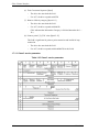
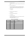
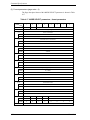
Revision History
(1/1)
Edition
Date
Revised section (*1)
(Added/Deleted/Altered)
Details
01
2004.07.28
—
—
*1 Section(s) with asterisk (*) refer to the previous edition when those were deleted.
C141-C008
This page is intentionally left blank.
Preface
This manual explains concerning the MAT3073FC, MAT3147FC, MAT3300FC,
MAU3036FC, MAU3073FC, MAU3147FC series 3.5 inch hard disk drives with
internal Fibre channel controller.
The purpose of this manual is to provide the specifications and functions of Fibre
channel (FC) for use of these magnetic disk drives incorporated into user systems,
and to present the information necessary for creating host system software. This
manual is written for users who have a basic knowledge of hard disk drives and
their use in computer systems.
The composition of manuals related to these disk drives and the range of subjects
covered in this manual are shown in “Manual Organization,” provided on a
subsequent page. Please use these other manuals along with this manual as
necessary.
The organization of this manual, related reference manual and conventions for
alert messages follow.
Overview of Manual
This manual consists of the following six chapters, glossary, abbreviation, and
index:
Chapter 1 Fibre Channel Interface
This chapter describes the topology, physical and electrical requirements, interface
protocol, and other operations of the Fibre channel (FC) interface which connects
the MAT3073FC, MAT3147FC, MAT3300FC, MAU3036FC, MAU3073FC,
MAU3147FC.
Chapter 2 Command Processing
This chapter describes the basic logical specifications related to Fibre channel
processing.
Chapter 3 Data Buffer Management
This chapter describes the data buffer configuration, data transfer processing
functions and cache operations.
Chapter 4 Command Specifications
This chapter describes detailed command specifications and how to use them.
C141-C008
i
Preface
Chapter 5 Sense Data and Error Recovery Methods
This chapter describes the configuration and contents of sense data which report to
the host system when an error occurs, etc., key information necessary for error
recovery, recommended procedures for error recovery to be executed through host
system software and retry processing.
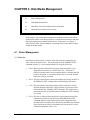
Chapter 6 Disk Media Management
This chapter describes the procedure for initializing the disk media, methods of
treating media defects and data recovery methods.
Glossary
The glossary explains technical terms which are necessary to the reader’s
understanding when reading this manual.
Acronyms and Abbreviations
This list shows the full spelling of abbreviations used in this manual.
Index
ii
C141-C008
Preface
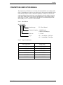
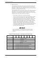
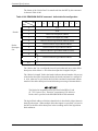
CONVENTIONS USED IN THIS MANUAL
The model name of disk drives covered by this manual differs in its ending suffix
(Note 1) depending on its device type (three types), the electrical conditions of the
Fibre channel interface used to connect the disk drive to the host system and its
capacity and data format at the time it was shipped, but in this manual, except in
cases where models need to be especially distinguished, a representative model
name (Note 2) is used. In addition, these disk drives are called Intelligent Disk
Drive (IDD), “drive” or “device” in this manual.
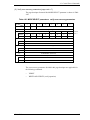
Note 1: Model Name
M AT 3 300 FC
Interface type
FC: Fibre Channel
Formatted capacity (1,000MB units)
* 1MB=1,000,000bytes
Disk size
3: 3.5 inch
Type
AT: 1 inch height, 10,025 rpm
AU: 1 inch height, 15,000 rpm
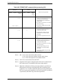
Note 2: Typical model name
C141-C008
Type model name
Model name
MAT3300
MAT3300FC
MAT3147
MAT3147FC
MAT3073
MAT3073FC
MAU3147
MAU3147FC
MAU3073
MAU3073FC
MAU3036
MAU3036FC
iii
Preface
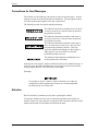
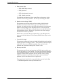
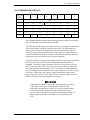
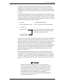
Conventions for Alert Messages
This manual uses the following conventions to show the alert messages. An alert
message consists of an alert signal and alert statements. The alert signal consists
of an alert symbol and a signal word or just a signal word.
The following are the alert signals and their meanings:
This indicates a hazardous situation likely to result in
serious personal injury if the user does not perform
the procedure correctly.
This indicates a hazardous situation could result in
serious personal injury if the user does not perform
the procedure correctly.
This indicates a hazardous situation could result in
minor or moderate personal injury if the user does
not perform the procedure correctly. This alert
signal also indicates that damages to the product or
other property, may occur if the user does not
perform the product correctly.
This indicates information that could help the user
use the product more efficiently.
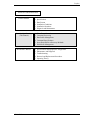
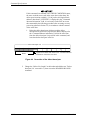
In the text, the alert signal is centered, followed below by the indented message. A
wider line space precedes and follows the alert message to show where the alert
message begins and ends. The following is an example:
(Example)
It is possible to use bit 7 and bit 6 of the control byte as an inherent
control field in future product specifications. It is recommended that
the INIT specify zero in this field.
Attention
Please forward any comments you may have regarding this manual.
To make this manual easier for users to understand, opinions from readers are
needed. Please write your opinions or requests on the Comment at the back of this
manual and forward it to the address described in the sheet.
iv
C141-C008
Preface
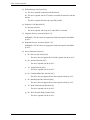
MANUAL ORGANIZATION
Product Manual
1.
2.
3.
4.
5.
6.
Outline
Specifications
Data Format
Installation Conditions
Installation Procedure
Diagnosis and Maintenance
Interface Specifications
(This Manual)
1.
2.
3.
4.
5.
6.
Fibre Channel Interface
Command Processing
Data Buffer Management
Command Specifications
Sense Data and Error Recovery Methods
Disk Media Management
Maintenance Manual
1.
2.
3.
4.
5.
Specifications and Equipment Configuration
Maintenance and Diagnosis
Troubleshooting
Removal and Replacement Procedures
Operating Theory
C141-C008
v
Preface
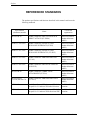
REFERENCED STANDARDS
The product specifications and functions described in this manual conform to the
following standards:
Specification
(document) number
vi
Name
Concerned
organization
NCITS TR-19
FIBRE CHANNEL PRIVATE LOOP SCSI
DIRECT ATTACH (FC-PLDA)
American National
Standards Institute
(ANSI)
ANSI X3. 230-1994
FIBRE CHANNEL PHYSICAL AND
SIGNALING INTERFACE (FC-PH)
American National
Standards Institute
(ANSI)
ANSI X3. 297-1996
FIBRE CHANNEL PHYSICAL AND
SIGNALING INTERFACE-2 (FC-PH-2)
American National
Standards Institute
(ANSI)
ANSI X3. 272-199x
FIBRE CHANNEL ARBITRATED LOOP
(FC-AL)
American National
Standards Institute
(ANSI)
ANSI X3. 269-199x
FIBRE CHANNEL PROTOCOL FOR SCSI
(SCSI-FCP)
American National
Standards Institute
(ANSI)
NCITS TR-20
FIBRE CHANNEL FABRIC LOOP
ATTACHMENT (FC-FLA)
American National
Standards Institute
(ANSI)
NCITS Project
1133-D, Revision 7.0
FIBRE CHANNEL ARBITRATED LOOP-2
(FC-AL-2)
American National
Standards Institute
(ANSI)
SFF-8045
Small Form Factor (SFF) document SFF-8045,
40-pin SCA-2 Connector W/Parallel Selection
Small From Factor
committe
SFF-8067
Small Form Factor (SFF) document SFF-8067,
40-pin SCA-2 Connector W/Bi-directional ESI
Small From Factor
committe
C141-C008
Contents
CHAPTER 1
Fibre Channel Interface ........................................................... 1-1
1.1 Topologies in Fibre Channel Interface..................................................... 1-2
1.1.1
Node/port ............................................................................................. 1-3
1.1.2
Link...................................................................................................... 1-3
1.1.3
Arbitrated loop..................................................................................... 1-3
1.1.4
Port bypass circuit (BC) ...................................................................... 1-4
1.1.5
Encoding & decoding .......................................................................... 1-4
1.1.6
Buffer-to-buffer frame transfer ........................................................... 1-5
1.2 Information Transmitted on the Loop ...................................................... 1-5
1.2.1
Ordered sets (refer to FC-PH, section 11.4) ........................................ 1-6
1.2.1.1 Primitive signals .................................................................................. 1-7
1.2.1.2 Frame delimiters.................................................................................. 1-7
1.2.1.3 Primitive sequence............................................................................... 1-7
1.2.2
Frame structure (refer to FC-PH, chapter 17) ..................................... 1-8
1.3 Physical Requirements, Electrical Requirements .................................. 1-15
1.3.1
Interface connector ............................................................................ 1-15
1.3.2
Signal function in SFF8045 mode..................................................... 1-17
1.3.3
Signal function in SFF8067 mode..................................................... 1-23
1.4 Drive Operation on the Loop.................................................................. 1-24
1.4.1
Loop initialization ............................................................................. 1-24
1.4.2
Arbitration ......................................................................................... 1-29
1.4.3
Communication between initiator and target .................................... 1-29
1.5 Ordered Sets (Refer to FC-PH, Section 11.4 and FC-AL, Chapter 6) .. 1-32
1.6 Basic Link Service.................................................................................. 1-33
C141-C008
1.6.1
Abort sequence (ABTS) .................................................................... 1-35
1.6.2
Basic accept (BA_ACC).................................................................... 1-36
1.6.3
Basic reject (BA_RJT)....................................................................... 1-37
vii
Contents
1.7 Extended Link Service............................................................................1-38
1.7.1
N_Port login (PLOGI/PLOGI_ACC) ................................................1-40
1.7.1.1 Port/node name format ......................................................................1-42
1.7.1.2 Common service parameter ...............................................................1-44
1.7.1.3 Class 3 service parameter ..................................................................1-46
1.7.2
Port logout (LOGO/LOGO_ACC) ....................................................1-49
1.7.3
Process login (PRLI/PRLI_ACC)......................................................1-50
1.7.3.1 Service parameter pages ....................................................................1-51
1.7.3.2 Service parameter response pages .....................................................1-53
1.7.4
Process logout (PRLO/PRLO_ACC).................................................1-55
1.7.4.1 Logout parameter pages.....................................................................1-57
1.7.4.2 Logout parameter response pages......................................................1-58
1.7.5
Port discovery (PDISC/PDISC_ACC)...............................................1-59
1.7.6
Discover address (ADISC/ADISC_ACC) .........................................1-59
1.7.7
Reinstate recovery qualifier (RRQ/RRQ_ACC)................................1-61
1.7.8
Read link error status block (RLS/RLS_ACC)..................................1-62
1.7.9
Third party process logout (TPRLO/TPRLO_ACC).........................1-64
1.7.9.1 Logout parameter pages.....................................................................1-65
1.7.10 Link service reject (LS_RJT).............................................................1-67
1.7.11 Fabric login (FLOGI/FLOGI_ACC)..................................................1-69
1.7.12 RNC/RNC_ACC................................................................................1-71
1.7.13 FAN....................................................................................................1-74
1.8 Extended Link Service (Loop Initialization)..........................................1-75
1.8.1
Loop initialization select master (LISM)...........................................1-77
1.8.2
Assign AL_PA frame (LIFA, LIPA, LIHA, LISA)..........................1-78
1.8.3
Position map information (LIRP, LILP)............................................1-79
1.9 FC-4 Device Data ...................................................................................1-80
1.9.1
FCP CMND .......................................................................................1-80
1.9.1.1 Control field (FCP_CNTL)................................................................1-82
1.9.1.2 Command descriptor block................................................................1-85
1.9.2
FCP XFER RDY................................................................................1-87
1.9.3
FCP DATA ........................................................................................1-89
1.9.4
FCP RSP ............................................................................................1-92
1.9.4.1 FCP status ..........................................................................................1-94
viii
C141-C008
Contents
1.9.4.2 FCP response information ................................................................. 1-95
1.9.4.3 FCP sense information ...................................................................... 1-96
1.10 Errors on Loop (Refer to FC-PH , Section 29.9).................................. 1-97
1.11 Enclosure Service Interface (ESI) ........................................................ 1-99
1.11.1 Data transfer protocol ........................................................................ 1-99
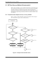
1.11.2 Enclosure discovery phase .............................................................. 1-101
1.11.3 COMMAND phase.......................................................................... 1-102
1.11.4 READ/WRITE phase....................................................................... 1-103
1.11.5 SES sense codes............................................................................... 1-104
1.11.6 Enclosure Initiated ESI transfer ...................................................... 1-104
1.11.6.1 EIE discovery................................................................................ 1-104
1.11.6.2 EIE operations............................................................................... 1-106
1.11.6.3 Enclosure requested information .................................................. 1-107
1.12 Public Loop ........................................................................................ 1-117
1.13 Dual Loop........................................................................................... 1-118
CHAPTER 2
Command Processing ............................................................. 2-1
2.1 Command Format..................................................................................... 2-1
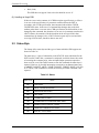
2.2 Status Byte................................................................................................ 2-6
2.3 Outline of Command Processing.............................................................. 2-8
2.3.1
Single commands................................................................................. 2-8
2.3.2
Command link ................................................................................... 2-15
2.4 Command Queuing Function ................................................................. 2-16
2.4.1
Untagged queuing.............................................................................. 2-16
2.4.2
Tagged queuing ................................................................................ 2-17
2.5 UNIT ATTENTION Condition .............................................................. 2-19
C141-C008
2.5.1
Generation of the UNIT ATTENTION condition............................. 2-19
2.5.2
Response and release condition at UNIT ATTENTION
condition hold state............................................................................ 2-20
2.5.3
UNIT ATTENTION condition multiple hold ................................... 2-21
ix
Contents
2.6 Sense Data Hold State ............................................................................2-21
2.7 Command Processing Exceptions ..........................................................2-21
2.7.1
Overlapping commands .....................................................................2-21
2.7.2
Illegal LUN specification ..................................................................2-22
2.7.3
Reserved operation code....................................................................2-22
2.7.4
Command processing in the not ready state ......................................2-23
2.7.5
Error recovery processing..................................................................2-25
2.7.6
Reset processing ................................................................................2-26
2.7.7
Fatal hardware errors .........................................................................2-30
2.8 Data Block Addressing ...........................................................................2-30
CHAPTER 3
2.8.1
Definition of data space .....................................................................2-30
2.8.2
Logical block addressing ...................................................................2-33
2.8.3
Variable TPI/BPI ...............................................................................2-34
Data Buffer Management......................................................... 3-1
3.1 Data Buffer ...............................................................................................3-1
3.1.1
Data buffer configuration and basic operation ....................................3-1
3.1.2
Operation mode setting........................................................................3-5
3.2 Look-Ahead Cache Feature ......................................................................3-7
3.2.1
Caching operation ................................................................................3-8
3.2.2
Caching parameters............................................................................3-10
3.2.3
Look-Ahead operation, Look-Ahead volume....................................3-12
3.3 Write Cache ............................................................................................3-13
CHAPTER 4
Command Specifications ........................................................ 4-1
4.1
x
Control/Sense Commands ......................................................................4-1
4.1.1
TEST UNIT READY (00) ...................................................................4-1
4.1.2
INQUIRY (12) .....................................................................................4-2
4.1.3
READ CAPACITY (25) ....................................................................4-15
4.1.4
MODE SELECT (15) ........................................................................4-16
4.1.5
MODE SELECT EXTENDED (55) ..................................................4-69
4.1.6
MODE SENSE (1A) ..........................................................................4-71
C141-C008
Contents
4.1.7
MODE SENSE EXTENDED (5A).................................................... 4-78
4.1.8
REZERO UNIT (01).......................................................................... 4-80
4.1.9
START/STOP UNIT (1B) ................................................................. 4-80
4.1.10 RESERVE (16)................................................................................... 4-82
4.1.11 RESERVE EXTENDED (56) ........................................................... 4-85
4.1.12 RELEASE (17) ................................................................................... 4-86
4.1.13 RELEASE EXTENDED (57)............................................................. 4-87
4.1.14 REQUEST SENSE (03) ..................................................................... 4-87
4.1.15 LOG SELECT (4C) ............................................................................ 4-90
4.1.16 LOG SENSE (4D) .............................................................................. 4-94
4.1.17 PERSISTENT RESERVE IN (5E) (not supported) ......................... 4-118
4.1.18 PERSISTENT RESERVE OUT (5F) (not supported) ..................... 4-125
4.1.19 REPORT LUNS (A0)....................................................................... 4-130
4.1.20 REPORT DEVICE IDENTIFIER (A3)............................................ 4-132
4.1.21 SET DEVICE IDENTIFIER (A4).................................................... 4-134
4.2 Data Access Commands ....................................................................... 4-135
4.2.1
READ (08)....................................................................................... 4-135
4.2.2
READ EXTENDED (28)................................................................. 4-136
4.2.3
WRITE (0A) .................................................................................... 4-137
4.2.4
WRITE EXTENDED (2A).............................................................. 4-139
4.2.5
WRITE AND VERIFY (2E) ........................................................... 4-140
4.2.6
VERIFY (2F) ................................................................................... 4-141
4.2.7
SEEK (0B) ....................................................................................... 4-142
4.2.8
SEEK EXTENDED (2B)................................................................. 4-143
4.2.9
SET LIMITS (33) (not supported) .................................................. 4-144
4.2.10 SYNCHRONIZE CACHE (35)........................................................ 4-147
4.3 Format Commands ............................................................................... 4-148
4.3.1
FORMAT UNIT (04) ...................................................................... 4-148
4.3.2
REASSIGN BLOCKS (07) ............................................................. 4-159
4.3.3
READ DEFECT DATA (37)........................................................... 4-163
4.3.4
READ DEFECT DATA (B7) .......................................................... 4-168
4.4 Maintenance, Diagnostic Commands................................................... 4-169
C141-C008
4.4.1
SEND DIAGNOSTIC (1D) ............................................................. 4-169
4.4.2
RECEIVE DIAGNOSTIC RESULTS (1C) .................................... 4-180
xi
Contents
CHAPTER 5
4.4.3
WRITE BUFFER (3B) ....................................................................4-186
4.4.4
READ BUFFER (3C) ......................................................................4-193
4.4.5
READ LONG (3E)...........................................................................4-197
4.4.6
WRITE LONG (3F) .........................................................................4-199
4.4.7
WRITE SAME (41) .........................................................................4-200
Sense Data and Error Recovery Methods.............................. 5-1
5.1 Sense Data ................................................................................................5-1
5.1.1
Sense data format.................................................................................5-1
5.1.2
Sense data basic information ...............................................................5-3
5.1.3
Sense data additional information .....................................................5-13
5.2 INIT Error Recovery Methods (Recommended)....................................5-14
5.2.1
Termination status analysis and error recovery methods ..................5-14
5.2.2
Sense data analysis and error recovery methods ...............................5-16
5.2.3
Error logging......................................................................................5-24
5.3 Disk Drive Error Recovery Processing ..................................................5-24
CHAPTER 6
5.3.1
Error states and retry processing procedures .....................................5-24
5.3.2
Auto alternate block allocation processing........................................5-26
5.3.3
Error recovery processing control .....................................................5-28
Disk Media Management ......................................................... 6-1
6.1 Defect Management..................................................................................6-1
6.2 Disk Media Initialization..........................................................................6-4
6.2.1
Initialization during installation...........................................................6-4
6.2.2
Re-initialization ...................................................................................6-5
6.3 Data Block Verification Methods (Recommended) .................................6-7
6.4 Alternate Block Allocation Processing ....................................................6-8
xii
C141-C008
Contents
Glossary ......................................................................................................... GL-1
Acronyms and Abbreviations........................................................................ AB-1
Index .................................................................................................................IN-1
C141-C008
xiii
Contents
Illustrations
Figures
Figure 1.1 Example of FC-AL connection............................................................ 1-2
Figure 1.2 Port bypass circuit ............................................................................... 1-4
Figure 1.3 Buffer-to-buffer frame transfer............................................................ 1-5
Figure 1.4 Data category on the loop.................................................................... 1-6
Figure 1.5 Format of ordered sets ......................................................................... 1-7
Figure 1.6 Frame format ....................................................................................... 1-8
Figure 1.7 Examples of exchange ....................................................................... 1-14
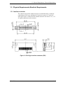
Figure 1.8 SCA2 type interface connector (IDD) ............................................... 1-15
Figure 1.9 Fibre channel output circuit............................................................... 1-22
Figure 1.10 Fibre channel input circuit............................................................... 1-22
Figure 1.11 Process for selecting loop master .................................................... 1-27
Figure 1.12 Loop master operation ..................................................................... 1-28
Figure 1.13 Command transfer ........................................................................... 1-30
Figure 1.14 Transfer ready (X_RDY) , response transfer (RSP)........................ 1-30
Figure 1.15 Write data transfer ........................................................................... 1-31
Figure 1.16 Read data transfer ............................................................................ 1-31
Figure 1.17 Header field of the basic link service .............................................. 1-34
Figure 1.18 Abort sequence (ABTS) .................................................................. 1-35
Figure 1.19 Basic accept (BA_ACC).................................................................. 1-36
Figure 1.20 Basic reject (BA_RJT)..................................................................... 1-37
Figure 1.21 Header field of the extended link service ........................................ 1-38
Figure 1.22 Payload field of the PLOGI frame................................................... 1-40
Figure 1.23 Payload field of the PLOGI_ACC frame ........................................ 1-41
Figure 1.24 Port logout (LOGO/LOGO_ACC) .................................................. 1-49
Figure 1.25 Process login (PRLI/PRLI_ACC).................................................... 1-50
Figure 1.26 Service parameter pages .................................................................. 1-51
Figure 1.27 Service parameter response pages ................................................... 1-53
Figure 1.28 Process logout (PRLO/PRLO_ACC) .............................................. 1-55
Figure 1.29 Payload field of the process logout (PRLO/PRLO_ACC) .............. 1-56
Figure 1.30 Logout parameter pages................................................................... 1-57
Figure 1.31 Logout parameter response pages.................................................... 1-58
Figure 1.32 Discover address (ADISC/ADISC_ACC) ...................................... 1-59
Figure 1.33 Reinstate recovery qualifier (RRQ/RRQ_ACC) ............................. 1-61
Figure 1.34 Read link error status block (RLS/RLS_ACC) ............................... 1-62
Figure 1.35 Third party process logout (TPRLO/TPRLO_ACC)....................... 1-64
xiv
C141-C008
Contents
Figure 1.36
Figure 1.37
Figure 1.38
Figure 1.39
Figure 1.40
Figure 1.41
Figure 1.42
Figure 1.43
Figure 1.44
Figure 1.45
Figure 1.46
Figure 1.47
Figure 1.48
Figure 1.49
Figure 1.50
Figure 1.51
Figure 1.52
Figure 1.53
Figure 1.54
Figure 1.55
Figure 1.56
Figure 1.57
Figure 1.58
Figure 1.59
Figure 1.60
Figure 1.61
Figure 1.62
Figure 1.63
Figure 1.64
Logout parameter pages ...................................................................1-65
Link service reject (LS_RJT) ...........................................................1-67
Fabric login (FLOGI) .......................................................................1-69
Fabric login (FLOGI_ACC) .............................................................1-70
RNC/RNC_ACC .............................................................................1-71
FAN ..................................................................................................1-74
Extended link service (loop initialization) .......................................1-75
Loop initialization select master (LISM) .........................................1-77
Assign AL_PA frame (LIFA, LIPA, LIHA, LISA) ........................1-78
Position map information (LIRP, LILP) ..........................................1-79
Header field of the FCP CMND.......................................................1-80
Control field (FCP_CNTL) ..............................................................1-82
Command descriptor block ..............................................................1-85
Header field of the FCP XFER RDY ...............................................1-87
Header field of the FCP DATA........................................................1-89
Header field of the FCP RSP............................................................1-92
FCP status.........................................................................................1-94
FCP response information ................................................................1-95
FCP sense information .....................................................................1-96
Enclosure service data transfer protocol ........................................1-100
Discovery flow chart ......................................................................1-101
COMMAND, WRITE phase ..........................................................1-102
Byte/bit alignment in ESI ...............................................................1-103
READ phase ...................................................................................1-103
Enclosure initiated ESI request ......................................................1-105
Prepare for removal ........................................................................1-106
EIE operation phases ......................................................................1-107
Public loop configuration ...............................................................1-117
General public loop initialization sequence ...................................1-118
Figure 2.1 General read data transfer sequence.....................................................2-8
Figure 2.2 General write data transfer sequence ...................................................2-9
Figure 2.3 Combination of SOF and EOF primitives used for
transferring frames.............................................................................2-11
Figure 2.4 Example of establishing logical connections between the
INIT and IDD.....................................................................................2-12
Figure 2.5 Loop initialization after establishing connections with the
INIT, and subsequent processing.......................................................2-14
Figure 2.6 TARGET RESET outline sequence ...................................................2-27
Figure 2.7 Data space configuration ....................................................................2-32
Figure 3.1 Data buffer configuration (in the case of 8 cache segments) ...............3-2
C141-C008
xv
Contents
Figure 3.2 Example of data buffer operation during read..................................... 3-3
Figure 3.3 Example of data buffer operation during write ................................... 3-5
Figure 4.1 MODE SELECT parameter structure................................................ 4-19
Figure 4.2 Reserve right and the third party reserve function ............................ 4-84
Figure 4.3 SET LIMITS command: specifying the range where
access is permitted........................................................................... 4-145
Figure 4.4 Correction of the defect descriptor .................................................. 4-162
Figure 5.1 Analysis of the termination status ..................................................... 5-14
xvi
C141-C008
Contents
Tables
Table 1.1 Frame header format..............................................................................1-8
Table 1.2 R_CTL .................................................................................................1-10
Table 1.3 Type .....................................................................................................1-10
Table 1.4 F_CTL..................................................................................................1-11
Table 1.5 BASIC LINK SERVICES ...................................................................1-12
Table 1.6 EXTENDED LINK SERVICES .........................................................1-12
Table 1.7 Extended Link Services-Loop Initialization........................................1-13
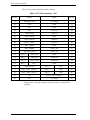
Table 1.8 FC-SCA connector: CN1 ....................................................................1-16
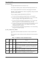
Table 1.9 Charge supply to the drive...................................................................1-17
Table 1.10 Characteristics of Fault LED out signal ............................................1-17
Table 1.11 Definition of motor start/mated control.............................................1-18
Table 1.12 Electric requirement for input control ...............................................1-19
Table 1.13 Electric requirement for SEL_n inputs..............................................1-19
Table 1.14 Electric requirement for DEV_CTRL_CODE inputs........................1-20
Table 1.15 Definition of device control codes.....................................................1-20
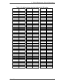
Table 1.16 Arbitrated loop physical address (AL_PA) values ............................1-21
Table 1.17 Output characteristics of –parallel ESI..............................................1-23
Table 1.18 AL_PA value/priority ........................................................................1-25
Table 1.19 LIP sequences ....................................................................................1-26
Table 1.20 Ordered sets specification .................................................................1-32
Table 1.21 Basic link service specification .........................................................1-33
Table 1.22 Extended link data specification........................................................1-38
Table 1.23 Port/node name format ......................................................................1-42
Table 1.24 Common service parameter ...............................................................1-44
Table 1.25 Class 3 service parameter ..................................................................1-46
Table 1.26 F_CTL................................................................................................1-90
Table 1.27 Detail errors and action......................................................................1-97
Table 1.28 Actions by recipient...........................................................................1-98
Table 1.29 COMMAND bytes definition ..........................................................1-102
Table 1.30 ASC/ASCQ defined for ESI conditions ..........................................1-104
Table 1.31 Enclosure request.............................................................................1-107
Table 1.32 Action code ......................................................................................1-108
Table 1.33 Enclosure initiated ESI page format................................................1-108
Table 1.34 Device standard inquiry data ...........................................................1-109
Table 1.35 Device addresses page .....................................................................1-110
Table 1.36 Loop position map page...................................................................1-111
Table 1.37 Initiate LIP action specific bits........................................................1-111
Table 1.38 Device identification page ...............................................................1-112
Table 1.39 Device temperature..........................................................................1-112
C141-C008
xvii
Contents
Table 1.40 Port parameters ............................................................................... 1-113
Table 1.41 Link status page ............................................................................. 1-114
Table 1.42 Transmitting and receiving of frames at the interface .................... 1-119
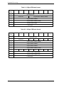
Table 2.1 6-Byte CDB basic format...................................................................... 2-2
Table 2.2 10-Byte CDB basic format.................................................................... 2-2
Table 2.3 12-Byte CDB basic format.................................................................... 2-3
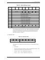
Table 2.4 Operation code ...................................................................................... 2-3
Table 2.5 Control byte........................................................................................... 2-5
Table 2.6 Status..................................................................................................... 2-6
Table 2.7 Fill byte ............................................................................................... 2-15
Table 2.8 Sense data in not ready state ............................................................... 2-23
Table 2.9 Outline of disk drive error recovery processing ................................. 2-25
Table 2.10 Comparison between FC and SCSI about definition ........................ 2-26
Table 2.11 Reset processing during write........................................................... 2-29
Table 3.1 Parameters for controlling reconnection timing ................................... 3-6
Table 3.2 Cache control parameters.................................................................... 3-11
Table 4.1 Standard INQUIRY data....................................................................... 4-4
Table 4.2 VERSION field ..................................................................................... 4-5
Table 4.3 Command queuing ................................................................................ 4-7
Table 4.4 Version descriptor ................................................................................. 4-9
Table 4.5 Command support data ....................................................................... 4-10
Table 4.6 Support ................................................................................................ 4-11
Table 4.7 VPD information................................................................................. 4-12
Table 4.8 VPD information: VPD identifier list ................................................ 4-12
Table 4.9 VPD information: device serial No.................................................... 4-13
Table 4.10 VPD information: operation mode................................................... 4-14
Table 4.11 READ CAPACITY data ................................................................... 4-16
Table 4.12 MODE SELECT command (Group 0) parameter
configuration ..................................................................................... 4-21
Table 4.13 MODE SELECT parameters............................................................. 4-24
Table 4.14 MODE SELECT parameters: read/write error recovery
parameters ......................................................................................... 4-25
Table 4.15 Combination of error recovery flags................................................. 4-30
Table 4.16 MODE SELECT parameters: disconnect/reconnect
parameters ......................................................................................... 4-34
Table 4.17 MODE SELECT parameters: format parameters ............................ 4-38
Table 4.18 MODE SELECT parameters: each parameters of
pages 3, 4, and C in detail ................................................................ 4-42
Table 4.19 MODE SELECT parameters: drive parameters............................... 4-43
xviii
C141-C008
Contents
Table 4.20 MODE SELECT parameters: verify error recovery
parameters ..........................................................................................4-45
Table 4.21 MODE SELECT parameters: caching parameters ...........................4-47
Table 4.22 MODE SELECT parameters: control mode parameters ..................4-53
Table 4.23 TST ....................................................................................................4-54
Table 4.24 QErr ...................................................................................................4-55
Table 4.25 MODE SELECT parameters: notch parameters...............................4-57
Table 4.26 MODE SELECT parameters: informational exception
control page........................................................................................4-59
Table 4.27 MRIE ................................................................................................4-61
Table 4.28 Interval timer .....................................................................................4-62
Table 4.29 MODE SELECT parameters: fibre channel control
parameters ..........................................................................................4-63
Table 4.30 RR_TOV UNITS ...............................................................................4-66
Table 4.31 CONTROL_MCM.............................................................................4-66
Table4.32 MODE SELECT parameters: additional error recovery
parameters ..........................................................................................4-67
Table 4.33 MODE SELECT EXTENDED command (group 2)
parameter configuration .....................................................................4-70
Table 4.34 Mode page..........................................................................................4-72
Table 4.35 MODE SENSE data type specifications............................................4-73
Table 4.36 MODE SENSE command (group 0) parameter
configuration ......................................................................................4-75
Table 4.37 MODE SENSE EXTENDED command (group 2)
parameter configuration .....................................................................4-79
Table 4.38 PC (page control) ................................................................................4-91
Table 4.39 LOG SELECT command parameter configuration ...........................4-91
Table 4.40 Page code ...........................................................................................4-92
Table 4.41 Page descriptor...................................................................................4-92
Table 4.42 "Page Code" assignment for the log pages ........................................4-95
Table 4.43 Support log page (X'00') ....................................................................4-96
Table 4.44 Buffer overrun/underrun page (X'01') ...............................................4-97
Table 4.45 Write error count page (X'02') ...........................................................4-98
Table 4.46 Write errors recovered without delays
(page 02, code 0000) ..........................................................................4-99
Table 4.47 Write errors recovered with possible delays
(page 02, code 0001) ..........................................................................4-99
Table 4.48 Total write errors posted (page 02, code 0002) ...............................4-100
Table 4.49 Total recoverable write errors posted to INIT
(page 02, code 0003) ........................................................................4-100
Table 4.50 Total write bytes processed (page 02, code 0005)...........................4-101
Table 4.51 Total unrecoverable write errors posted to INIT
(page 02, code 0006) ........................................................................4-101
Table 4.52 Read error count page (X'03')..........................................................4-102
C141-C008
xix
Contents
Table 4.53 Read errors recovered without delays (page 03, code 0000) .......... 4-102
Table 4.54 Read errors recovered with possible delays
(page 03, code 0001) ....................................................................... 4-103
Table 4.55 Total read errors posted (page 03, code 0002)................................ 4-103
Table 4.56 Total recoverable read errors posted to INIT
(page 03, code 0003) ....................................................................... 4-104
Table 4.57 Total read bytes processed (page 03, code 0005) ........................... 4-104
Table 4.58 Total unrecoverable read errors posted to INIT
(page 03, code 0006) ....................................................................... 4-105
Table 4.59 Verify error count page (X'05')....................................................... 4-105
Table 4.60 Verify errors recovered without delays
(page 05, code 0000) ....................................................................... 4-106
Table 4.61 Vefiry errors recovered with possible delays
(page 05, code 0001) ....................................................................... 4-106
Table 4.62 Total verify errors posted (page 05, code 0002) ............................. 4-107
Table 4.63 Total recoverable verify errors posted to INIT (page 05,
code 0003)....................................................................................... 4-107
Table 4.64 Total verify bytes processed (page 05, code 0005) ........................ 4-108
Table 4.65 Total unrecoverable verify errors posted to INIT
(page 05, code 0006) ....................................................................... 4-108
Table 4.66 Non-medium error count page (X'06') ............................................ 4-109
Table 4.67 Temperature page (X'0D')............................................................... 4-109
Table 4.68 Temperature (page 0D, code 0000) ................................................ 4-110
Table 4.69 Reference temperature (page 0D, code 0001)................................. 4-110
Table 4.70 Start-stop cycle counter page (X'0E') ............................................. 4-111
Table 4.71 Date of manufacture (page 0E, code 0001) .................................... 4-111
Table 4.72 Accounting date (page 0E, code 0002) ........................................... 4-112
Table 4.73 Specified cycle count over device lifetime
(page 0E, code 0003)....................................................................... 4-112
Table 4.74 Start-stop cycle counter (page 0E, code 0004) ............................... 4-113
Table 4.75 Application client page (X'0F') ....................................................... 4-114
Table 4.76 General usage application client parameter data
(page 0F, code 0000-003F) ............................................................. 4-114
Table 4.77 Self-test result page (X'10')............................................................. 4-115
Table 4.78 Self-test result parameter data (page 10, code 0001-0014) ............ 4-115
Table 4.79 Self-test results values .................................................................... 4-116
Table 4.80 SMART status page (X'2F') ............................................................ 4-117
Table 4.81 SMART data page (X'38')............................................................... 4-117
Table 4.82 PERSISTENT RESERVE IN service actions................................. 4-118
Table 4.83 PERSISTENT RESERVE IN parameter data for READ
KEYS .............................................................................................. 4-119
Table 4.84 PERSISTENT RESERVE IN parameter data for READ
RESERVATIONS........................................................................... 4-121
Table 4.85 Format of reservation descriptors ................................................... 4-122
xx
C141-C008
Contents
Table 4.86
Table 4.87
Table 4.88
Table 4.89
Table 4.90
Persistent reservations scope ...........................................................4-123
Persistent reservations type codes ...................................................4-124
PERSISTENT RESERVE OUT service action codes .....................4-126
PERSISTENT RESERVE OUT parameter list ...............................4-127
PERSISTENT RESERVE OUT service action and valid
parameters ......................................................................................4-129
Table 4.91 REPORT LUNS parameter list........................................................4-131
Table 4.92 REPORT DEVICE IDENTIFIER parameter list.............................4-133
Table 4.93 SET DEVICE IDENTIFIER parameter list.....................................4-135
Table 4.94 Combinations of RdInh and WrInh .................................................4-145
Table 4.95 Defect list format .............................................................................4-150
Table 4.96 FORMAT UNIT command parameter list configuration................4-151
Table 4.97 Defect descriptor: byte distance from index format .......................4-154
Table 4.98 Defect descriptor: physical sector address format..........................4-155
Table 4.99 FORMAT UNIT command defect processing ...............................4-157
Table 4.100 REASSIGN BLOCK command: defect data list
configuration ..................................................................................4-160
Table 4.101 Defect data type .............................................................................4-163
Table 4.102 Defect data format .........................................................................4-164
Table 4.103 READ DEFECT DATA command: defect data
configuration ..................................................................................4-164
Table 4.104 Defect data conditions ...................................................................4-166
Table 4.105 READ DEFECT DATA command (B7):
defect data configuration................................................................4-169
Table 4.106 Self-diagnosis test..........................................................................4-170
Table 4.107 Error recovery control flags during the self-diagnosis test ...........4-171
Table 4.108 SEND DIAGNOSTIC command: parameter list
configuration ..................................................................................4-173
Table 4.109 Page code .......................................................................................4-173
Table 4.110 SEND DIAGNOSTIC parameters: page code list........................4-174
Table 4.111 SEND DIAGNOSTIC parameters: logical/physical
address conversion .........................................................................4-175
Table 4.112 Specifying address format .............................................................4-175
Table 4.113 SELF-TEST ...................................................................................4-176
Table 4.114 ESI page.........................................................................................4-178
Table 4.115 ESI page format .............................................................................4-178
Table 4.116 Fault LED test page .......................................................................4-179
Table 4.117 RECEIVE DIAGNOSTIC RESULTS command:
response data configuration ...........................................................4-181
Table 4.118 RECEIVE DIAGNOSTIC RESULTS response data:
page code list..................................................................................4-182
Table 4.119 RECEIVE DIAGNOSTIC RESULTS response data:
logical/physical address conversion...............................................4-183
C141-C008
xxi
Contents
Table 4.120
Table 4.121
Table 4.122
Table 4.123
Table 4.124
Table 4.125
Table 4.126
Table 4.127
Table 4.128
Table 4.129
Address format.............................................................................. 4-184
ESI page code................................................................................ 4-184
ESI page format ............................................................................ 4-185
Short enclosure status ................................................................... 4-185
WRITE BUFFER transfer mode................................................... 4-187
WRITE BUFFER command: buffer data
(mode = 000, 001) ........................................................................ 4-188
READ BUFFER transfer mode..................................................... 4-193
READ BUFFER command: buffer data
(mode = 0000, 0001) .................................................................... 4-194
READ BUFFER command: buffer descriptor .............................. 4-196
READ BUFFER command: echo buffer descriptor .................... 4-197
Table 5.1
Table 5.2
Table 5.3
Table 5.4
Expanded sense data format.................................................................. 5-2
Sense key inherent information ............................................................ 5-5
Sense key............................................................................................... 5-6
Additional Sense Code and Additional Sense Code
Qualifier ............................................................................................... 5-7
Table 5.5 Sense data error classification ............................................................ 5-17
Table 5.6 Error recovery processing procedures ................................................ 5-20
Table 5.7 Disk drive errors and number of retries .............................................. 5-29
xxii
C141-C008
CHAPTER 1 Fibre Channel Interface
1.1
Topologies in Fibre Channel Interface
1.2
Information Transmitted on the Loop
1.3
Physical Requirements, Electrical Requirements
1.4
Drive Operation on the Loop
1.5
Ordered Sets
(Refer to FC-PH, Section 11.4 and FC-AL, Chapter 6)
1.6
Basic Link Service
1.7
Extended Link Service
1.8
Extended Link Service (Loop initialization)
1.9
FC-4 Device Data
1.10
Errors on Loop (Refer to FC-PH, Section 29.9)
1.11
Enclosure Service Interface (ESI)
1.12
Public Loop
1.13
Dual Loop
This chapter describes the topology, physical and electrical requirements,
interface protocol and operation of the fibre channel interface.
C141-C008
1-1
Fibre Channel Interface
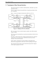
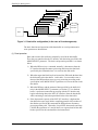
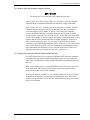
1.1 Topologies in Fibre Channel Interface
Three kind of topologies are defined in ANSI standards. (Arbitrated Loop, Fabric
and Point-to-Point)
The drive supports Arbitrated Loop and Fabric as the primary topologies for the
drive connections.
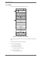
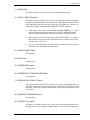
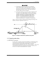
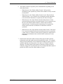
Figure 1.1 shows the example of connection for disk drives in FC-AL.
Figure 1.1 Example of FC-AL connection
BC are port bypass circuits on the back plane commonly, where Node mean the
Target or initiator.
Each Loop signal is transmitted by one-way direction and made of electrical wires
called “link”.
Each node is connected to the loop vial the port which the node owns. Each port
consists of the receiver which receives information from the loop and the
transmitter which sends information.
In this example, each node has two ports building two independent loops.
Information is propagated between the nodes on the loop through serial signals.
This section describes the Node, Port, BC and link forming the above diagram
and the signals propagated on the link.
1-2
C141-C008
1.1 Topologies in Fibre Channel Interface
1.1.1 Node/port
Any device connected to Fibre Channel topology is called “node”.
In the application of this drive, the drive itself and the initiator are the nodes.
Each node has at least one port to connect other nodes and the port is called
N_port.
Especially, in FC-AL, the port is called “NL_Port” where “NL” stands for node
loop.
The drive provides two ports and each port is connected to each FC-AL.
See Figure 1.1.
1.1.2 Link
Each port provides both Receiver and Transmitter.
The drive uses electrical wires (differential signal) to receive or transmit the
information.
This pair of wires is called a “link”.
See Figure 1.1.
The drive Link Rate is selectable either 2 Gbps or 1 Gbps by DEV_CTL signals
on the Back Plane via SCA-2 Connector.
It is commonly use for both Ports.
See Table 1.12.
1.1.3 Arbitrated loop
Arbitrated loops are defined as “private loop” or “public loop”.
Private loop has no FL_port (for fabric loop) and all nodes are NL_ports.
If there is a FL_port which is managing the loop, the loop is called a public.
This can connect up to 126 active NL_port and one FL_port to the same loop.
And the NL_ports use arbitration to establish an Initiator-Target connections.
See Figure 1.1.
C141-C008
1-3
Fibre Channel Interface
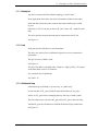
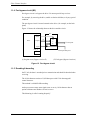
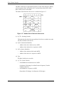
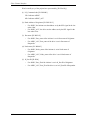
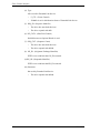
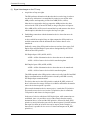
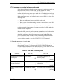
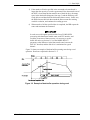
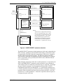
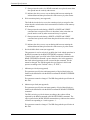
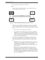
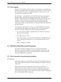
1.1.4 Port bypass circuit (BC)
Port bypass circuit is to bypass the drive if it cannot provide loop services.
For example, by removing the drive, unable to obtain valid data, or by any special
condition.
The port bypass circuit is located external to the drive. (for example, on the back
plane)
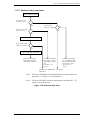
Figure 1.2 shows the relationship between the drive and the circuit.
Port_B
BC
Select
(1)
Drive
M
U
X
Output
To next port
(2)
Input
Port_A
From previous port
(1) Regular route (Bypass circuit off)
(2) Via bypass (Bypass circuit on)
Figure 1.2 Port bypass circuit
1.1.5 Encoding & decoding
On FC-AL, the data is encoded prior to transmission and should be decoded when
receiving.
The 10-bit character consists of 1,024 data space with 13-bit data mapped 1
control character.
This method is called 8B/10B encoding.
And to prevent too many same signal (ones or zeros), 10-bit character has an
option to balance total numbers of ones or zeros.
This balancing is called “running disparity”.
1-4
C141-C008
1.2 Information Transmitted on the Loop
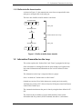
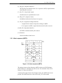
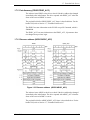
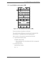
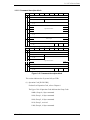
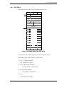
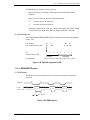
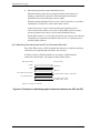
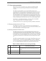
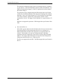
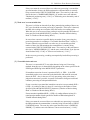
1.1.6 Buffer-to-buffer frame transfer
As shown in Figure 1.3, data transmission occurs from an output buffer in the
node part to an input buffer in the node port.
The basic unit of buffer-to-buffer transfer is the frame.
Transmit Buffer
8bit
8bit
8bit
8bit
in NL_Port
8B/10B Encoder
Serializer
Serial Transfer on FC loop
Deserializer
8B/10B Decoder
8bit
8bit
8bit
in NL_Port
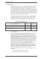
8bit
Receive Buffer
Figure 1.3 Buffer-to-buffer frame transfer
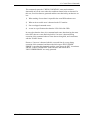
1.2 Information Transmitted on the Loop
This section explains the “Ordered Sets” and “Frame” propagated on the loop.
Since information is exchanged between the ports through serial signals, both
loop control information and information at user level are defined in frame
format.
The information on the loop is categorized into two groups.
One is “ordered sets” and the other is called “frame”.
Ordered sets consist of four 10-bit character to control port circuit mainly.
And the frame consists of FC-4 Device Data for SCSI protocol and Link Data to
control Fibre Channel layer.
The communication between the ports is done by using the frame defined in FCPH.
The frame has the port address of source and destination, frame control
information and user protocol (SCSI-Command, data and etc.) information.
C141-C008
1-5
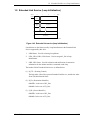
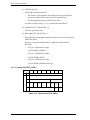
Fibre Channel Interface
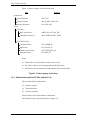
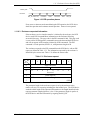
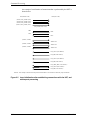
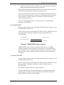
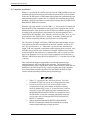
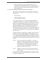
Figure 1.4 shows category of the data on the loop.
Data
Example
Ordered Sets
Frame Delimiters
–SOF, EOF
Primitive Signals
–Idle, R_RDY, OPN, CLS
Primitive Sequence
–LIP, LPE, LPB
Frame
Link Data
Basic Link Service
–ABTS, BA_ACC, BA_RJT
Extended Link Service
–PLOGI, PRLI, PDISC, LISM
FC-4 Device Data
Command Frame
–FCP_CMND_IU
Data Frame
–FCP_DATA_IU
Transfer-ready Frame
–FCP_XFER_RDY_IU
Response Frame
–FCP_RSP_IU
Notes:
a)
Ordered Sets is mainly used for control of port circuit.
b) FC-4 Device Data is used for implementation SCSI protocol.
c)
Link Data is used for transmission and response for port control data.
Figure 1.4 Data category on the loop
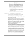
1.2.1 Ordered sets (refer to FC-PH, section 11.4)
There are three kind of Ordered Sets.
(1) –Primitive signals
(2) –Frame delimiters
(3) –Primitive sequence
which consist of four 10 bit character combination.
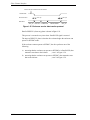
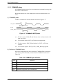
Each ordered set has string of data shown in Figure 1.5.
1-6
C141-C008
1.2 Information Transmitted on the Loop
The K28.5 special character is always used as the first character of all ordered
sets.
K28.5
Dxx.y
Dxx.y
Dxx.y
Figure 1.5 Format of ordered sets
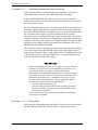
1.2.1.1 Primitive signals
Primitive Signals have a control function to indicate status of the drive or to
perform some operation to the port being connected.
Primitive Signals are recognized when one ordered set is detected.
A minimum of six Primitive Signals must be transmitted between each frame.
The name and the function of Primitive Signals is below.
a)
Idle; to indicate the port can transmit or receive the frame
b) R_RDY; to indicate the port has an area for receiving the frame
c)
ARBx; to request the right to use the loop. x = AL_PA of the requesting port
d) ARB (FO); to request the right (= lowest priority) to use the loop
e)
OPN; to inform the transmission of the frame to the destination port
f)
CLS: to inform the release of the loop
1.2.1.2 Frame delimiters
Frame Delimiters mark the beginning and end of frames.
They are called Start-of-frame (SOF) delimiters and End-of-frame (EOF)
delimiters.
1.2.1.3 Primitive sequence
Primitive Sequence is a control function and requires to be detected.
The name and the function of Primitive sequence is below.
a)
LPB; When received, the drive enables the port bypass circuit and bypasses
the loop.
b) LPE; When received, the drive disables the port bypass circuit and connects
to the loop.
C141-C008
1-7
Fibre Channel Interface
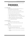
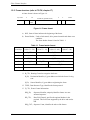
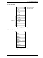
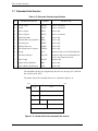
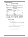
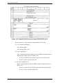
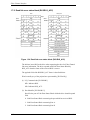
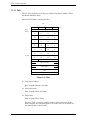
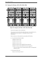
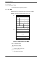
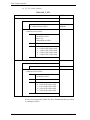
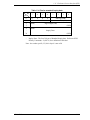
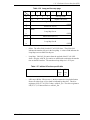
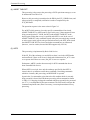
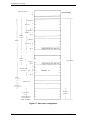
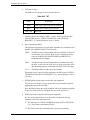
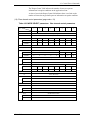
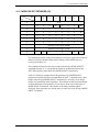
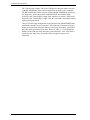
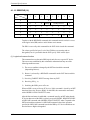
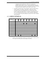
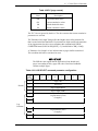
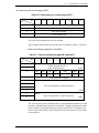
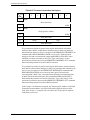
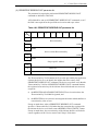
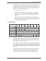
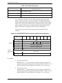
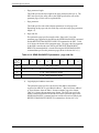
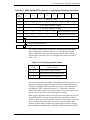
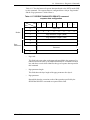
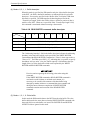
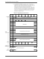
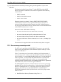
1.2.2 Frame structure (refer to FC-PH, chapter 17)
A frame format is shown in Figure 1.6.
byte count
4
fill words
SOF
word count
24
Frame
Header
Payload
6
1
4
4
CRC
EOF
1
1
0-2048+64 (optional header)
0-528
min24
fill words
min6
Figure 1.6 Frame format
a)
SOF; Start of frame indicates the beginning of the frame.
b) Frame Header; Used as link control, drive protocol transfer and detect error
condition.
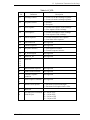
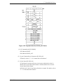
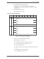
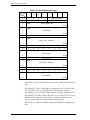
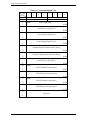
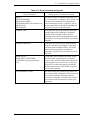
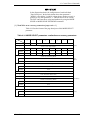
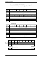
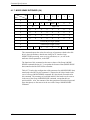
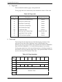
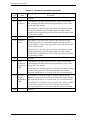
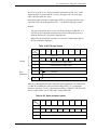
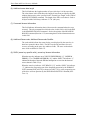
The frame header format is listed in Table 1.1.
Table 1.1 Frame header format
word/byte
0 (bits 31 – 24)
0
R_CTL
D_ID
1
reserved
S_ID
2
TYPE
F_CTL
3
SEQ_ID
4
1 (bits 23 – 16)
2 (bits 15 – 08)
DF_CTL
SEQ_CNT
OX_ID
5
3 (bits 07 – 00)
RX_ID
OFFSET
*1 R_CTL; Routing Control to categorize the frame.
D_ID; Destination Identifier, N_port address to which the frame is being
sent.
S_ID;
Source Identifier, N_port address originating the frame.
*2 TYPE; Data Structure Type, identifies the frame protocol.
*3 F_CTL; Frame Control information
SEQ_ID;
Sequence Identifier, uniquely identifies frames in a nonstreamed sequence.
DF_CTL;
Data Field Control, specifies the optional headers in the
payload. This field is not supported by the drive and used as
00h.
SEQ_CNT; Sequence Count, identifies the order of the frames.
1-8
C141-C008
1.2 Information Transmitted on the Loop
c)
OX_ID;
Originator Exchange Identifier, assigned by the originator of an
exchange. This value is similar to Queue Tag in SCSI and must
be unique for a pair between the initiator and the drive.
RX_ID;
Responder Exchange Identifier, generated by the responder for
an exchange.
OFFSET;
Defines the relative displacement of the first byte of the payload
from the base address of the command.
Payload; Data field, must be multiple of four bytes.
–
If the frame is FC-4 Device Data, the payload has SCSI CDB,
Read/Write Data or status/sense information.
–
If the frame is Link Data, the payload has control information for the
drive or the response data to the initiator.
d) CRC; Calculates without including SOF and EOF delimiters.
e)
EOF; End of frame indicates the end of a frame.
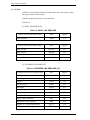
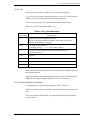
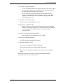
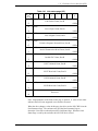
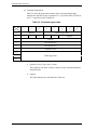
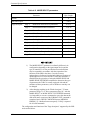
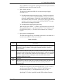
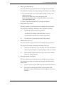
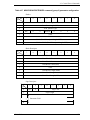
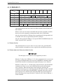
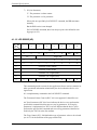
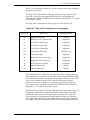
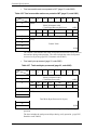
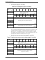
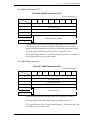
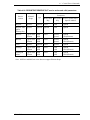
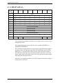
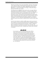
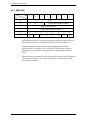
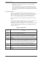
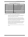
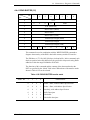
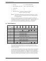
*1: R_CTL (Routing Control)
The high order bits (bits 31-28) specify the frame type as follows.
0000 = FC-4 Device_Data frame
0010 = Extended Link_Data frame
0011 = FC-4 Link_ Data frame
0100 = Video_ Data frame
1000 = Basic Link_ Data frame
1100 = Link_ Control frame
Others = Reserved
The low order bits (bits 27-24) specify the Information field values.
Those values have the meaning with combination with the value of the high
order bits (31-28).
C141-C008
1-9
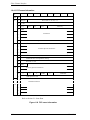
Fibre Channel Interface
Table 1.2 R_CTL
High order bits
low order bits
Use
Type=0x08
0000
0000 Uncategorized
0001 Solicited Data
0010 Unsolicited Control
0011 Solicited control
0100 Unsolicited data
0101 Data descriptor
0110 Unsolicited
0111 Command status
Not supported
Read and write data
Not supported
Not supported
Not supported
Transfer ready
Command
Response
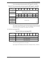
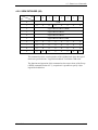
Type=0x01
0010
0000 Uncategorized
0001 Solicited data
0010 Unsolicited control
0011 Solicited control
0100 Unsolicited data
0101 Data descriptor
0110 Unsolicited command
0111 Command status
Not supported
Not supported
Request
Reply
Not supported
Not supported
Not supported
Not supported
Type=0x00
1000
0000 No operation
0001 Abort sequence
0010 Remove connection
0011 Reserved
0100 Basic_Accept
0101 Basic_Reject
0110 Dedicated connecton
Preempted
0111 Reserved
Not supported
Request
Not supported
Reply
Reply
Not supported
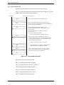
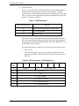
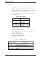
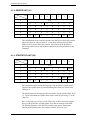
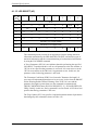
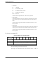
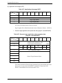
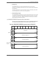
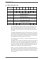
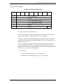
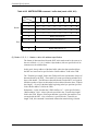
*2: Type (Data Structure Type)
Table 1.3 Type
R_CTL (4 highest order bit)
1000
0010
0000
Type Code
00
01
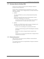
08
Use
Basic Link Service
Extended Link Service
SCSI FCP
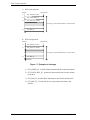
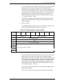
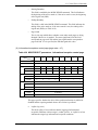
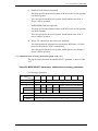
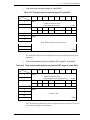
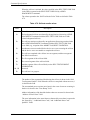
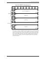
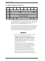
*3: F_CTL (Frame Control)
1-10
C141-C008
1.2 Information Transmitted on the Loop
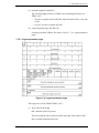
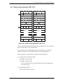
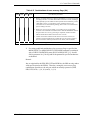
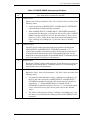
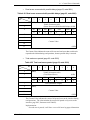
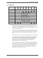
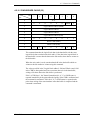
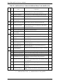
Table 1.4 F_CTL
Bit
Definition
Description
23
Exchange context
0 = Frame is from the exchange originator
1 = Frame is from the exchange responder
22
Sequence context
0 = Initiator
1 = Recipient
21
First sequence
0 = Not the first sequence of the exchange
1 = First sequence of the exchange
20
Last sequence
0 = Not the last sequence of the exchange
1 = Last sequence of the exchange
19
End of sequence
0 = Not the last frame of the sequence
1 = Last frame of the sequence
18
End connection
Not supported
17
Chained sequence
Not supported
16
Sequence initiative
0 = Hold sequence initiative
1 = Transfer sequence initiative
15
X_ID reassigned
Not supported
14
Invalid X_ID
Not supported
13
12
11
10
Reserved
9
Retransmitted Sequence
Not supported
8
Unidirectional transmit
Not supported
7
6
Continue sequence
condition
Not supported
5
4
Abort sequence condition
Not supported
3
Relative offset present
0 = Parameter field not meaningful
1 = Parameter field equals relative offset
2
Reserved
1
0
Fill data bytes End of data 00 = 0 byte of fill
field fill bytes
01 = 1 byte of fill
02 = 2 bytes of fill
03 = 3 bytes of fill
C141-C008
1-11
Fibre Channel Interface
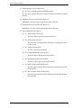
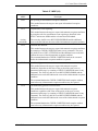
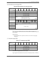
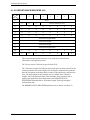
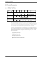
(1) Link Data
Link Data is used when the initiator transmit control code to the target or when
the target responses to the initiator.
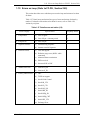
Link Data supported by the drive are listed below.
Link Service
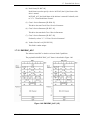
(1) BASIC LINK SERVICES
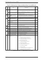
Table 1.5 BASIC LINK SERVICES
Basic Link Service Request Frames
Abbr.
Support
ABTS
Yes
Abbr.
Support
Basic_Accept
BA_ACC
Yes
Basic_Reject
BA_RJT
Yes
No Operation
NOP
No
Remove Connection (class1 only)
RMC
No
Abort Sequence
Basic Link Service Request Frames
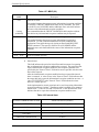
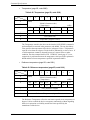
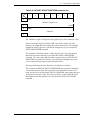
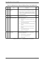
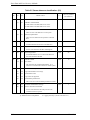
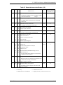
(2) EXTENDED LINK SERVICES
Table 1.6 EXTENDED LINK SERVICES (1/2)
Extended Link Service Request Frames
1-12
Abbr.
Support
Address Discovery
ADISC
Yes
Fabric Login
FLOGI
Yes
Logout
LOGO
Yes
Port Discovery
PDISC
Yes
Port Login
PLOGI
Yes
Process Login
PRLI
Yes
Process Logout
PRLO
Yes
Read Link Status
RLS
Yes
Report Node Capabilities
RNC
Yes
Reinstate Recovery Qualifier
RRQ
Yes
Register FC-4 Types Name Service
RFC-4
Yes
Third-party Process Logout
TRPLO
Yes
C141-C008
1.2 Information Transmitted on the Loop
Table 1.6 EXTENDED LINK SERVICES (2/2)
Extended Link Service Request Frames
Abbr.
Support
Read Exchange Status Block
RES
No
Request Sequence Initiative
RSI
No
Read Sequence Status Block
RSS
No
Extended Link Service Request Frames
Abbr.
Support
Accept
ACC
Yes
LS_RJT
Yes
Link Service Reject
•
Extended Link Services-Loop Initialization
Table 1.7 Extended Link Services-Loop Initialization
Extended Link Service Request Frames LOOP INITIALIZATION
Abbr.
Support
Select Master
LISM
Yes
Fabric Assign AL_PA
LIFA
Yes
Previously Acquired AL_PA
LIPA
Yes
Hard Assigned AL_PA
LIHA
Yes
Soft Assigned AL_PA
LISA
Yes
Report AL_PA Position Map
LIRP
Yes
Loop AL_PA Position Map
LILP
Yes
(2) FC-4 Device Data
Exchanges consist of two or more frame sequences between the initiator and the
target.
Exchanges starts from command frame by the initiator and ends at response frame
by the target.
Four FC-4 Device Data (FCP_CMND_IU, FCP_DATA_RDY_IU,
FCP_DATA_IU, FCP_RSP_IU) are used to implement SCSI protocol. Figure 1.7
explains the examples of Exchanges in case of SCSI write/read operation.
C141-C008
1-13
Fibre Channel Interface
a)
SCSI write operation
Initiator
Target (drive)
1)
FCP_CMND_IU (WT)
2)
FCP_XFER_RDY_IU
3)
FCP_DATA_IU (Write)
Exchange ; from command frame to response frame
:
4)
FCP_RSP_IU
b) SCSI read operation
Initiator
Target (drive)
1)
FCP_CMND_IU (RD)
3)
FCP_DATA_IU (Read)
Exchange ; from command frame to response frame
:
4)
FCP_RSP_IU
Figure 1.7 Examples of exchange
1) FCP_CMND_IU; includes SCSI command and the control information
2) FCP_DATA_RDY_IU; permits the data transmission from the initiator
to the drive
3) FCP_Data_IU; Read or Write data between the initiator and the drive
4) FCP_RSP_IU; Used by the drive to report status/sense data to the
initiator
1-14
C141-C008
1.3 Physical Requirements, Electrical Requirements
1.3 Physical Requirements, Electrical Requirements
1.3.1 Interface connector
The connector for the fibre channel loop bus is an unshielded SCA-2 connector
conforming to SCSI-3 type which has two 20-pin rows spaced 1.27 mm (0.05
inch) apart. Figure 1.8 shows the fibre channel connector. See Section 1.3.2, 1.3.3
for signal assignments on the connector.
Figure 1.8 SCA2 type interface connector (IDD)
C141-C008
1-15
Fibre Channel Interface
Table 1.8 lists signal assignments on the connector.
Table 1.8 FC-SCA connector: CN1
Pin No.
Signal
Signal
Pin No.
01
–EN bypass port A
+12V charge
21
02
+12V
GND
22
03
+12V
GND
23
04
+12V
+PortA_in
24
05
–Parallel ESI
–PortA_in
25
06
–Drive present
GND
26
07
Active LED out
+PortB_in
27
08
Power_Control
–PortB_in
28
09
Start_1/Mated
GND
29
10
Start_2/Mated
+PortA_out
30
11
–EN bypass port B
–PortA_out
31
12*
SEL_6
–DSK_WR
GND
32
13*
SEL_5
–DSK_RD
+PortB-out
33
14*
SEL_4
–ENCL_ACK
–PortB-out
34
15*
SEL_3
D(3)
GND
35
16
Fault LED out
SEL_2
D(2)
36*
17
DEV_CTRL_CODE_2
SEL_1
D(1)
37*
18
DEV_CTRL_CODE_1
SEL_0
D(0)
38*
19
+5V
DEV_CTRL_CODE_0
39
20
+5V
+5V charge
40
* Signal names in the right column of the table are those in parallel ESI
operation.
1-16
C141-C008
1.3 Physical Requirements, Electrical Requirements
1.3.2 Signal function in SFF8045 mode
(1) +12V charge, +5V charge
These signals are used to precharge of the internal circuits to avoid excessive
surge current while hot plugging is being operated.
Before power voltage pins (+12V and +5V) make contact, these precharge pins
mate early.
Precharge control circuits are external to the drive.
The voltage provided to the precharge signals are defined in Table 1.9.
Table 1.9 Charge supply to the drive
Charge Signal
Range of power supply
after charge complete
Max Surge to the
drive
Max Continuous
required the drive
+12V charge
12V +5%, –12%
6 Amps
1 Amps
+5V charge
5V +5%, –17%
6 Amps
1 Amps
(2) Fault LED out
The drive starts, and this signal lights when it detects internal failure.
1) Fault LED is turned on when asserting Enable Bypass signals for both ports.
2) Fault LED is turned on when the internal failure is detected.
a)
When losing synchronization on both ports
b) When detecting hardware error in the HDC chip
3) Fault LED is turned on when the host issues the corresponding command.
Note: The Fault LED will not be turned on if only one port loses synchronization.
The Fault LED out signal is an open-collector output. The LED and the current
limiting register are external to the drive. See Table 1.10.
Table 1.10 Characteristics of Fault LED out signal
State
C141-C008
Current
LED off
–100µA <IOH < 100µA
LED on
IOL > 30mA
Output Voltage
0 < VOL <0.5V
1-17
Fibre Channel Interface
(3) Active LED out
The signal indicates that the drive starts and is active.
Two alternative indication pattern is defined in SFF-8045 Specification Rev 4.2.
One is “hot plug implementation” for the drives in hot plugged environments.
The other is “legacy implementation” where the compatibility with previous SCSI
indication system is required.
The drive supports hot plug implementation described below.
a)
The Active LED out signal does not light if the drive is not connected.
b) The Active LED out signal blinks for approximately 0.5 sec. intervals when
the drive is spinning. It turns to light when the drive is ready.
c)
The Active LED out signal blinks for approximately 0.5 sec. intervals when
the drive is spin-down. It is turned off when the drive is not ready.
d) The Active LED out signal is turned off when the SCSI command is received
by the drive and during processing. And it changed to blink when the
command processing is completed.
e)
The Active LED out signal blinks for approximately 1.0 sec. intervals during
being processed Format Command.
(4) Start_1/Mated, Start_2/Mated
These signals controls the method to start the drive’s motor as described Table
1.11.
Also the signals are used to indicate to the drive that the drive has been mated to a
backplane.
Table 1.11 Definition of motor start/mated control
Case
1-18
Start_2/ Start_1/
Mated
Mated
Function
1
open
open
Drive is not mated to a backplane. The drive’s motor does NOT
spin up.
2
open
ground
Drive is mated to a backplane. The drive’s motor spins up when
the drive receives SCSI start command after a mating deskew
time has passed.
3
ground
open
Drive is mated to a backplane. The drive’s motor spins up after
a delay after a mating deskew time has passed.
4
ground
ground
Drive is mated to a backplane. The drive’s motor spins up
immediately after a mating deskew time has passed.
C141-C008
1.3 Physical Requirements, Electrical Requirements
The mating deskew time is minimum 250 msec.
A 10 KΩ pull up register to 5V for each signal is asserted on the drive.
The open and ground states should be controlled as in Table 1.12.
Table 1.12 Electric requirement for input control
State
Current
Voltage
open
20 µA <IIH < 20 µA
2.2V <VIH < 5.25V
ground
0 <IIL <–20 mA
–0.5V <VIL <0.7V
(5) Parallel ESI
This signal is not supported in SFF8045 mode.
When receiving either Receive Diagnostic Result or Send Diagnostic Command,
the drive will assert this signal to initiate SFF-8067 Enclosure Discovery Phase
and to execute ESI operations.
(6) SEL_0, _1, _2, _3, _4, _5, _6
These seven SEL lines are provided for the binary value of the loop identifier by
the backplane.
This identifier is name AL_PA and is used for 126 unique value except 00h.
These ID signals are tested by the drive when powered on.
SEL_6 is the most significant bit and SEL_0 is the least significant bit.
Electric requirement for the signals is listed in Table 1.13.
These signals with high state have approximately 10KΩ register on the
backplane.
Table 1.13 Electric requirement for SEL_n inputs
State
Current
Voltage
high
–20 µA <IIH < 20 µA
2.2V <VIH < 5.25V
low
–20 µA <IIL < 20 µA
–0.5V <VIL <0.7V
SEL. ID = (SEL_6, SEL_5, SEL_4, SEL_3, SEL_2, SEL_1, SEL_0)
C141-C008
1-19
Fibre Channel Interface
(7) DEV_CTRL_CODE [2, 1, 0]
DEV_CTRL_CODES Provide Link Rate, and Power Failure Warning (PFW) to
the drive.
Table 1.14 Electric requirement for DEV_CTRL_CODE inputs
State
Current
Voltage
high
–20 µA <IIH < 20 µA
2.2V <VIH < 5.25V
low
–20 µA <IIL < 20 µA
–0.5V <VIL <0.7V
Table 1.15 Definition of device control codes
Value
1-20
Function
Support
7
1.0625 GHZ - The FC interfaces for both ports of the
drive are set to run at a link rate of 1.0625 GHZ.
Yes
6
2.1250 GHZ - The FC interfaces for both ports of the
drive are set to run at a link rate of 2.1250 GHZ.
Yes
5
4.250 GHZ - The FC interfaces for both ports of the drive
are set to run at a link rate of 4.250 GHZ.
No
4 to 2
Reserved
No
1
Reserved for auto-negotiation of FC interface link rate.
No
0
Power Failure Warning
No
C141-C008
1.3 Physical Requirements, Electrical Requirements
Table 1.16 Arbitrated loop physical address (AL_PA) values
AL_PA
(hex)
SEL ID
(hex)
AL_PA
(hex)
SEL ID
(hex)
AL_PA
(hex)
SEL ID
(hex)
EF
00
A3
E8
01
9F
2B
4D
56
2C
4C
E4
02
9E
57
2D
4B
58
E2
03
9D
2E
4A
59
E1
04
9B
2F
49
5A
E0
05
98
30
47
5B
DC
06
97
31
46
5C
DA
07
90
32
45
5D
D9
08
8F
33
43
5E
D6
09
88
34
3C
5F
D5
0A
84
35
3A
60
D4
0B
82
36
39
61
D3
0C
81
37
36
62
D2
0D
80
38
35
63
D1
0E
7C
39
34
64
CE
0F
7A
3A
33
65
CD
10
79
3B
32
66
CC
11
76
3C
31
67
CB
12
75
3D
2E
68
CA
13
74
3E
2D
69
C9
14
73
3F
2C
6A
C7
15
72
40
2B
6B
C6
16
71
41
2A
6C
C5
17
6E
42
29
6D
C3
18
6D
43
27
6E
BC
19
6C
44
26
6F
BA
1A
6B
45
25
70
B9
1B
6A
46
23
71
B6
1C
69
47
1F
72
B5
1D
67
48
1E
73
B4
1E
66
49
1D
74
B3
1F
65
4A
1B
75
B2
20
63
4B
18
76
B1
21
5C
4C
17
77
AE
22
5A
4D
10
78
79
AD
23
59
4E
0F
AC
24
56
4F
08
7A
AB
25
55
50
04
7B
AA
26
54
51
02
7C
A9
27
53
52
01
7D
A7
28
52
53
A6
29
51
54
A5
2A
4E
55
C141-C008
1-21
Fibre Channel Interface
(8) Port out (+port A_out, +port B_out)
Port out signals are output by the drive.
These signals are differential copper with a termination of 50 Ω embedded in
HDC Chip and 100 Ω to output ECL signal label on the loop .
The output circuit is shown in Figure 1.9.
36Ω
+ Port Out
TX+
220Ω
HDC
outside of the drive
36Ω
TX–
– Port Out
Figure 1.9 Fibre channel output circuit
(9) Port in (+Port A_in, +Port B_in)
These signals are differential copper with 100 Ω termination embedded in HDC
chip and are AC coupled with capacitors.
The input circuit is shown in Figure 1.10.
36Ω
RX+
+ Port In
220Ω
HDC
36Ω
– Port In
RX–
Figure 1.10 Fibre channel input circuit
(10) –EN Bypass Port A/–EN Bypass Port B
These Enable Port Bypass Circuit (PBC) by a bypass signals, which is located
external to the drive.
The functional diagram of these signals is described in Section 1.1.4.
When the drive asserts this signal (low), the Port bypass circuit bypasses the drive
which is connected.
1-22
C141-C008
1.3 Physical Requirements, Electrical Requirements
This signal is asserted when;
a)
detecting of the Loop Port Bypass primitive sequence
b) being removed of the drive from the loop
c)
loss of receive clock
d) loss of transmission clock
e)
detecting hardware error within the drive
This signal is negated when the drive detects a Loop Port Enable primitive
sequence.
(11) –Drive present ; This signal connected to the ground.
1.3.3 Signal function in SFF8067 mode
(1) –Parallel ESI
–Parallel ESI signal is used to request the enclosure to provide the SEL_x (x = 06) addressing signals and to request ESI block Read/Write operation.
Table 1.13 defines electronic characteristics of this signal.
Table 1.17 Output characteristics of –parallel ESI
State
high
low
Current Drive Available
–100 µA <IOH < 100 µA
IOL >1.6 mA
Output Voltage
0< VOH <5.25V
0< VOL <0.5V
Table 1.17 shows how –Parallel ESI signal is used in the Enclosure Service
Interface.
(2) –DSK_WR, DSK_RD, ENCL_ACK, D(3), D(2), D(1), D(0)
The SEL_x (x = 0-6) signals change into communication control signals when
–Parallel ESI signal is asserted.
C141-C008
1-23
Fibre Channel Interface
1.4 Drive Operation on the Loop
This section describes the following as the operations which the drive is required
to perform at FC level:
•
Loop initialization
•
Arbitration
•
Communication between the initiator and target
1.4.1 Loop initialization
(1) Process Outline
Loop Initialization is a process for the purpose listed below.
•
To obtain Arbitrated Loop Physical Address (AL_PA) because the drive has
no valid address when powered on.
•
To indicate the error on the loop to the other NL_ports.
•
To reset particular drive by the initiator.
And the trigger to start Loop Initialization is called LIP.
Loop Initialization is occurred as follows.
a)
The drive is powered on.
b) The drive (or all NL_Ports if powered on simultaneously) requests to
start Loop Initialization.
; see 1.4.1(3) (LIP)
c)
Select loop master (responsible for processing Loop Initialization)
; see 1.4.1(4) (LISM)
d) Each NL_ports on the loop starts the process for obtaining AL_PA.
; see 1.4.1(5) (LIFA/LIPA/LIHA/LISA)
e)
1-24
Each NL_Ports obtains unique AL_PA and Loop Initialization is terminated.
C141-C008
1.4 Drive Operation on the Loop
(2) AL_PA
This sub-section describes the addresses (AL_PA) used on the loop.
AL_PA is an 8-bit character and when encoded to 10 bits, AL_PA has an equal
number of ones or zeros to maintain neutral running disparity.
Table 1.18 shows the AL_PA values and the priority used on the loop.
Details of AL_PA is described in Table 1.16.
Table 1.18 AL_PA value/priority
Values (hex)
Priority & Use
00
Highest priority and assigned for FL_port.
The drive does not assume the existence of this value on the loop.
(because of assuming private loop)
01-EF
126 valid NL_Port address
01 (highest priority) < ===== > EF (Lowest priority)
F0
Has no priority and used for fairness algorithm and for Loop
Initialization process
F1-F6
not used
F7, F8
reserved for Loop initialization
FF
vendor Specific reset
others
not used
Most common method for the disk drive will be to have the backpanel provide a
hard assigned address.
If the drive failed to obtain a hard assigned address, the drive would obtain the
address by soft assigned method. For details, refer to sub-section (5).
(3) LIP (Loop Initialization on Primitive)
Loop Initialization is generated by sending any LIPs in Table 1.19.
The NL_Port which received a LIP then transmit the LIP to the next port on the
loop.
This cycle terminates when the NL_Port that started the initialization process
receives the LIP.
C141-C008
1-25
Fibre Channel Interface
Table 1.19 LIP sequences
LIP type
Use
Description
LIP (F7, F7)
LIP (F7, AL_PS)
Initializing
Loop
A NL_Port requests to obtain AL_PA
*1
LIP (AL_PD, AL_PS)
Reset the port
The source port (AL_PS) requests to reset
the destination port (AL_PD).
The selected port performs to reset after
loop initialization.
*2
LIP (F8, AL_PS)
Loop failure
The NL_Port has detected an input failure
AL_PS is the AL_PA of the source port.
*1
LIP (F8, F7)
Loop failure
The NL_Port has detected an input failure
and the port could not obtain an AL_PA.
*1
LIP (FF, AL_PS)
Reset ALL
port
A Vendor Specific reset executes for both
port.
Note:
*1: The drive can issue the LIP.
*2: The drive receives the LIP but does NOT issue LIP (AL_PD, AL_PS).
(4) LISM (Loop Initialization Select Master)
This sub-section describes a process to select the loop master to which the
function for proceeding with each process of Loop Initialization is given.
Selecting the loop master proceeds as follows. (Figure 1.11)
Figure 1.11 shows the example that three ports exist on the loop and each port has
an unique Port Name which algebraic relationship is n+2>n+1>n.
Steps [1] through [6] are for selecting a port with the smallest unique port name
of those assigned at manufacture, as the loop master.
Steps [8] and [9] are for confirming that the port, which became the loop master
by steps [1] through [6], has become the loop master again.
1-26
C141-C008
1.4 Drive Operation on the Loop
Step
Port Name n
[1] Transmits LISM with its own
port name to the next port.
n+1
LISM (n)
n+2
LISM (n+1)
LISM (n+2)
[2] Receives LISM from the upper
loop port.
LISM (n+2)
LISM (n)
[3] Compares the port name with its
own port name and transmits
LISM (n)
LISM with lower port name.
LISM (n+1)
LISM (n)
LISM (n+1)
[4] Receives LISM from the upper
loop port.
LISM (n+1)
LISM (n)
[5] Compares the port name with its
own port name and transmits
LISM (n)
LISM with lower port name.
LISM (n)
LISM (n)
LISM (n)
[6] Receives LISM from the upper
loop port.
LISM (n)
[7] Compares the port name with its
own port name and if they are
the same, the port becomes loop
master.
<loop master>
LISM (n)
LISM (n)
<non loop master> <non loop master>
[8] Loop master transmits ARB
(F0) ans waits for the ARB (F0) ARB (F0)
comes back.
[9] Loop master checks ARB (F0)
ARB (F0)
Note:
The value is assigned to each port uniquely in production.
Figure 1.11 Process for selecting loop master
C141-C008
1-27
Fibre Channel Interface
(5) LIFA/LIPA/LIHA/LISA
This sub-section describes a process for each port to obtain AL_PA.
Figure 1.12 shows the process for non loop master to obtain unique AL_PA after
ending a process for selecting the loop master.
Loop Master
Other NL_Port on the loop
LIFA
LIPA
LIHA
LISA
; LIFA is used to gather all fabric-assigned AL_PAs.
; LIPA is used to gather all previously-acquired AL_PAs.
The drive attempts to obtain same AL_PA if the drive obtained
the AL_PA in previous initilization.
; LIHA is used to gather all hard assigned AL_PAs.
The drive attempts to obtain AL_PA if it failed to obtain
AL_PA in LIPA.
The drive always attempts to obtain AL_PA when
a) powered on or
b) receiving LIP (AL_PD, AL-PS)
The drive always attempts to obtain same AL_PA.
; LISA is used to assign any remaining AL_PA bits.
The drive attempts to obtain AL_PA if it failed up to LIHA.
If the drive fails to obtain AL_PA in LISA, then the drive
goes into nonparticipating mode.
<== Each NL_Port obtains unique AL_PA here.
LIRP
<== LIRP and LILP may be caused by the loop master to
confirm the location and address on the loop.
LILP
; LIRP is used to record the relative positions on the loop.
; LILP is used to inform all NL_Ports of their relative
positions on the loop from the loop master.
CLS
Figure 1.12 Loop master operation
The abbreviation in this section is below.
LIFA; Loop Initialization Fabric Assigned
LIPA; Loop Initialization Previously Acquired
LIHA; Loop Initialization Hard Assigned
LISA; Loop Initialization Soft Assigned
LIRP; Loop Initialization Report Position
LILP; Loop Initialization Loop Position
1-28
C141-C008
1.4 Drive Operation on the Loop
1.4.2 Arbitration
For information to be exchanged between the ports connected to a loop, generally
the two ports (send side and receive side) must occupy the loop (placed in pointto-point connection state).
Arbitration is a process to win access right on the loop and must be done before
communicating with another port.
When the arbitration is finished, only a pair of a initiator and a target can
communicate each other on the loop.
The drive supports the method called “Access fairness”.
The process on the port supporting fairness movement is below.
a)
If two or more ports request to arbitrate, the port with the highest priority (the
port with smallest AL_PA value) wins the arbitration.
b) The port once won the arbitration cannot participate in the arbitration until
other port wins the arbitration and release the loop.
This method protects that the same port uses the loop consecutively.
1.4.3 Communication between initiator and target
This section shows the figure of the protocol using FC-4 Device Data on Fibre
Channel layer.
The following procedures are followed to send FC-4 device data.
•
Issue ARB by which the source of FC-4 device data asserts the occupation of
the loop.
•
After occupying the loop, the source issues “Open” to the destination.
•
The receiving station responds by R_RDY by the count by which it can
receive FC-4 device data.
•
The sending station sends FC-4 device data.
•
The sending station sends CLS to terminate the occupation of the loop.
A description of each FC-4 device data follows.
C141-C008
1-29
Fibre Channel Interface
(1) Command Transfer
Initiator
Target
When the initiator issues FCP_CMND_IU:
ARBx
OPN
R_RDY
FCP_CMND_IU
CLS
Figure 1.13 Command transfer
(2) Transfer Ready (X_RDY) , Response Transfer (RSP)
Initiator
Target
ARBx
When the target issues FCP_XFER_RDY_IU
or FCP_RSP_IU
OPN
R_RDY
FCP_XFER_RDY_IU or
FCP_RSP_IU
CLS
Figure 1.14 Transfer ready (X_RDY) , response transfer (RSP)
1-30
C141-C008
1.4 Drive Operation on the Loop
(3) Write Data Transfer
Initiator
Target
When the target recognizes
the sending of write data
ARBx
OPN
R_RDY
R_RDY
R_RDY
R_RDY
Write Data 1
R_RDY
Write Data 2
FCP_Data_IU
R_RDY
Write Data n
CLS
Figure 1.15 Write data transfer
(4) Read Data Transfer
Initiator
Target
ARBx
When the target sends read data:
OPN
R_RDY
Read Data 1
R_RDY
Read Data 2
R_RDY
:
Read Data n
CLS
Figure 1.16 Read data transfer
C141-C008
1-31
Fibre Channel Interface
1.5 Ordered Sets
(Refer to FC-PH, Section 11.4 and FC-AL, Chapter 6)
Table 1.20 shows the Ordered Sets specification.
This section describes handling of the Ordered Sets of this drive.
Table 1.20 Ordered sets specification (1/2)
No.
Frame Delimiters
Symbol
The drive can;
01
SOF Connect
Class 1
SOFc1
receive only (discard)
02
SOF Initiate
Class 1
SOFi1
receive only (discard)
03
SOF Normal
Class 1
SOFn1
receive only (discard)
04
SOF Initiate
Class 2
SOFi2
receive only (discard)
05
SOF Normal
Class 2
SOFn2
receive only (discard)
06
SOF Initiate
Class 3
SOFi3
receive or transmit
07
SOF Normal
Class 3
SOFn3
receive or transmit
08
SOF Initialize Loop
SOFiL
receive or transmit
09
EOF Terminate
EOFt
receive or transmit
10
EOF Disconnect-Terminate
EOFdt
receive only (discard)
11
EOF Abort
EOFa
receive only (discard)
12
EOF normal
EOFn
receive or transmit
13
EOF Disconnect-Terminate-Invalid
EOFdti
receive only (discard)
14
EOF Normal-Invalid
EOFni
receive only (discard)
No.
Primitive Signals
Symbol
The drive can;
01
Idle
Idle
receive or transmit
02
Receiver_Read
R_RDY
receive or transmit
03
Arbitrate
ARBx
receive or transmit
04
Arbitrate
ARB (F0)
receive or transmit
05
Open full-duplex
OPNyx
receive or transmit
06
Open half-duplex
OPNyy
receive
07
Open broadcast replicate
OPNfr
receive only (discard)
08
Open selective replicate
OPNyr
receive only (discard)
09
Slotted Loop – transfer
SLPyx
receive only (discard)
10
Slotted Loop – isoch
SLPyf
receive only (discard)
11
Slotted Loop – asynch
SLPff
receive only (discard)
12
Close
CLS
receive or transmit
13
Mark
MRKtx
receive only (discard)
1-32
C141-C008
1.6 Basic Link Service
Table 1.20 Ordered sets specification (2/2)
No.
Primitive Sequences
Symbol
The drive can;
01
Offline
OLS
receive only (discard)
02
Not_Operational
NOS
receive only (discard)
03
Link_Reset
LR
receive only (discard)
04
Link_Reset_Response
LRR
receive only (discard)
05
Loop Initialization
LIP (F7, F7)
receive or transmit
06
Loop Initialization
LIP (F7, x)
receive or transmit
07
Loop Initialization
LIP (F8, F7)
receive or transmit
08
Loop Initialization
LIP (F8, x)
receive or transmit
09
Loop Initialization
LIPfx
receive only
10
Loop Initialization
LIPyx
receive only
11
Loop Port Enable
LPEyx
receive only
12
Loop Port Enable all
LPEfx
receive only (discard)
13
Loop Port Bypass
LPByx
receive only
1.6 Basic Link Service
This section defines handling of the link service of this drive and handling of each
frame.
Table 1.21 shows the basic link service specification
Table 1.21 Basic link service specification
No.
Basic Link Service
Symbol
The drive can;
01
No Operation
NOP
receive only (discard)
02
Abort Sequence
ABTS
receive only
03
Basic Accept
BA_ACC
transmit if only the drive received ABTS
04
Basic Reject
BA_RJT
transmit if only the drive received ABTS
C141-C008
1-33
Fibre Channel Interface
The Basic Link Services supported by this drive are the Abort Sequence (ABTS)
and its responses, Basic Accept (BA_ACC) or Basic Reject (BA_RJT). Other
Basic Link Services are discarded.
The header field of the basic link service is defined in Figure 1.17.
Figure 1.17 Header field of the basic link service
(1) R_CTL.. (Routing Control)
The high order four bits (8h) represent Basic Link Service, and the low order
four bits each Basic Link Service.
(2) D_ID.. (Destination Identifier)
−
Address of the drive which receives ABTS.
−
Address of the initiator for a response to ABTS.
(3) S_ID.. (Source Identifier)
−
Address of the initiator which sends ABTS.
−
Address of the drive for a response to ABTS.
(4) Type
The Basic Link Service uses 00h.
(5) F_CTL.. (Frame Control)
−
Set 090000h for the transmission of ABTS.
(Originator of Exchange, Last Data Frame of Sequence, Transfer
Sequence Initiative)
−
Set 990000h for a response to ABTS.
(Responder of Exchange, Last Sequence of Exchange)
1-34
C141-C008
1.6 Basic Link Service
(6) SEQ_ID.. (Sequence Identifier)
The drive does not check this item. For a response to ABTS, respond with the
same SEQ_ID as received.
(7) DF_CTL.. (Data Field Control)
Set 00h because no optional header is used.
(8) SEQ_CNT.. (Sequence Count)
Set 0000h to indicate the first frame of a sequence.
(9) OX_ID.. (Originator Exchange Identifier)
−
Assigned for the initiator to begin the exchange of ABTS.
−
For a response to ABTS, respond with the same OX_ID as received.
(10) RX_ID.. (Responder Identifier)
Set FFFFh to indicate that RX_ID is unused.
(11) Parameter
Unused in the Basic Link Service.
1.6.1 Abort sequence (ABTS)
Figure 1.18 Abort sequence (ABTS)
The initiator issues an Abort Sequence (ABTS) to abort one SCSI Exchange
(SCSI CMD) or FC Exchange (one link service). For the header field, refer to
Section 1.6, "Basic Link Service."
As shown in the figure for the Abort Sequence frame, this ABTS frame has no
payload. The ABTS frame has a value of 81h in R_CTL of the header.
C141-C008
1-35
Fibre Channel Interface
1.6.2 Basic accept (BA_ACC)
xx
Figure 1.19 Basic accept (BA_ACC)
The drive responds with BA_ACC to the initiator when the received ABTS frame
is correct.
The payload field of the BA_ACC frame is described below.
For the header fields, refer to Section 1.6, “Basic Link Service.”
Word xx/ and byte y of the payload are represented by [PL:Wxx/By].
(1) SEQ_ID Valid.. [PL:W00/B0]
00h: Indicates that last SEQ_ID of word 0/byte 1 is invalid.
80h: Indicates that last SEQ_ID of word 0/byte 1 is valid.
(2) Last SEQ_ID.. [PL:W00/B1]
Indicates that SEQ_ID of last sequence aborted.
(3) OX_ID.. Aborted [PL:W01/B0-1]
Same value as OX_ID received for ABTS.
(4) RX_ID.. Aborted [PL:W01/B2-3]
Same value as RX_ID received for ABTS. (FFFFh)
1-36
C141-C008
1.6 Basic Link Service
(5) Lowest SEQ_CNT.. [PL:W02/B0-1] 0000h
(6) Highest SEQ_CNT.. [PL:W02/B2-3] FFFFh
1.6.3 Basic reject (BA_RJT)
xx
Figure 1.20 Basic reject (BA_RJT)
The drive responds with BA_RJT to the initiator when RX_ID of the received
ABTS frame is not FFFFh.
The payload field of the BA_RJT frame is described below. For the header field,
refer to Section 1.6, "Basic Link Service."
Word xx/ and byte y of the payload are represented by [PL:Wxx/By].
(1) Reason Code [PL:W00/B1]
03h: Logical error code returned when RX_ID of ABTS is not FFFFh.
(2) Reason Explanation [PL:W00/B2]
03h: Code of invalid OX_ID-RX_ID combination.
(3) Vender Unique (PL:W00/B3]
00h: Not supported by the drive.
C141-C008
1-37
Fibre Channel Interface
1.7 Extended Link Service
Table 1.22 Extended link data specification
No.
Extended Link Service
Symbol
The drive can;
01
N_Port Login
PLOGI
receive or transmit
02
Logout
LOGO
receive or transmit
03
Process Login
PRLI
receive only
04
Process Logout
PRLO
receive or transmit
05
Read Link Status
RLS
receive only
06
Reinstate Recovery Qualifier
RRQ
receive only
07
Port Discovery
PDISC
receive only
08
Address Discovery
ADISC
receive only
09
Third-Party Process Logout
TPRLO
receive only
10
Accept
ACC
transmit if only received Extended Link
11
Link Service Reject
LS_RJT
transmit if only received Extended Link
Service was illegal or has fails.
12
Fabric Login
FLOGI
transmit only
13
Report Node Capabilities
RNC
receive only
14
Fabric Address Notification
FAN
receive only
The Extended Link Services supported by this drive are Accept (ACC) and Link
Service Reject (LS_RJT).
The header field of the extended link service is defined in Figure 1.21.
Word
Header
0
0
1
2
<R_CTL>
2x
<S_ID>
2
<TYPE>
01
3
<SEQ_ID>
5
Byte
<D_ID>
1
4
3
<F_CTL>
<DF_CTL>
<OX_ID>
<SEQ_CNT>
<RX_ID>
<Parameter>
Figure 1.21 Header field of the extended link service
1-38
C141-C008
1.7 Extended Link Service
(1) R_CTL.. (Routing Control)
The high order four bits (2h) represent Extended Link Service, and the low
order four bits each Extended Link Service.
(2) D_ID.. (Destination Identifier)
−
Destination address for the frame.
(3) S_ID.. (Source Identifier)
−
Source address for the frame.
(4) Type
The Extended Link Service uses 01h.
(5) F_CTL.. (Frame Control)
−
Set 290000h for the Extended Link Service Command.
(Originator of Exchange, First Sequence of Exchange, Last Data Frame
of Sequence, Transfer Sequence Initiative)
−
Set 980000h for a response to the Extended Link Service Command.
(Responder of Exchange, Last Sequence of Exchange)
(6) SEQ_ID.. (Sequence Identifier)
−
The drive does not check this item.
−
The drive responds with FFh.
(7) DF_CTL.. (Data Field Control)
Set 00h because no optional header is used.
(8) SEQ_CNT.. (Sequence Count)
−
The drive does not check this item.
−
The drive responds with 0000h.
(9) OX_ID.. (Originator Exchange Identifier)
−
The drive responds with OX_ID received from the initiator.
(10) RX_ID.. (Responder Identifier)
Set FFFFh to indicate that RX_ID is unused.
(11) Parameter
Unused in the Extended Link Service.
C141-C008
1-39
Fibre Channel Interface
1.7.1 N_Port login (PLOGI/PLOGI_ACC)
The initiator issues PLOGI to establish the connection with the drive by notifying
the drive of the service parameter. The drive responds with PLOGI_ACC when
the frame of the received PLOGI is correct.
The payload field of the PLOGI frame is described in Figure 1.22, and that of the
PLOGI_ACC is in Figure 1.23.
For the header field, refer to Section 1.7, “Extended Link Service.”
Word xx/ and byte y of the payload are represented by [PL:Wxx/By].
1
2
3
4
5
6
7
8
Figure 1.22 Payload field of the PLOGI frame
1-40
C141-C008
1.7 Extended Link Service
98
1
2
3
4
5
6
7
8
Figure 1.23 Payload field of the PLOGI_ACC frame
(1) LS_Command code [PL:W00/B0]
03h: Indicates PLOGI.
02h: Indicates PLOGI_ACC.
(2) N_port Common Service Parameters [PL:W01-04]
For details, refer to "1.7.1.2 Common Service Parameter."
(3) N_Port Name [PL:W05/-06]
N_Port Name is used to specify two or more ports which a device has. In
PLOGI, the N_Port Name of the initiator is entered and the drive saves the
N_Port Name of the initiator.
In PLOGI_ACC, the N_Port Name of the drive is entered. For details, refer to
"1.7.1.1 Port/Node Name Format."
C141-C008
1-41
1.7 Extended Link Service
(1) Name Address Authority (NAA) [bit63-60]
0x5:
Denotes the format of IEEE Registered.
(2) Company_ID [bit59-36]
0x00000E:
Value registered in IEEE, denoting the company which has
supplied the device.
(3) Product ID [bit35-32]
The value is used either 0x0.
(4) Factory ID [bit31-28]
The value is used either h 0x0 or 0x1.
(5) Vendor Specified Identifier [bit27-4]
Unique value assigned to each device.
(6) Port Number [bit3-0]
C141-C008
0x0:
Device Node name
0x1:
Port A of the device
0x2:
Port B of the device
1-43
Fibre Channel Interface
1.7.1.2 Common service parameter
Table 1.24 Common service parameter
Continuos
Increase
5
(1) Highest version supported [Byte0]
Latest version number of FC-PH supported by the device.
09h: Denotes FC-PH version 4.3.
−
For ACC, the drive responds with 20h.
(2) Lowest version supported [Byte1]
Lowest version number of FC-PH supported by the device.
09h: Denotes FC-PH version 4.3.
−
For ACC, the drive responds with 20h.
(3) Buffer-to-buffer Credit [Byte2-3]
−
The drive does not check this field and operates assuming that Buffer to
buffer Credit is one.
−
For ACC, the drive responds with 0001h.
(4) Common features [Byte4-5]
a)
1-44
1b: Continuously Increasing Offset [bit7]
−
The drive responds with LS_RJT (03h, 0Fh) when (this bit) = 0b.
−
For ACC, the drive responds with 1b.
C141-C008
1.7 Extended Link Service
b) 0b: Random Relative Offset [bit6]
c)
−
The drive does not check this bit and does not support this function.
−
For ACC, the drive responds with 0b.
0b: Valid Vendor Version [bit5]
−
The drive does not check this bit and does not support this function.
−
For ACC, the drive responds with 0b.
d) 0b: N_Port/F_Port [bit4]
e)
f)
−
The drive responds with LS_RJT (03h, 0Fh) when (this bit) = 1b.
−
For ACC, the drive responds with 0b.
1b: Alternate BB_Credit Management [bit3]
−
The drive responds with LS_RJT (03h, 0F) when (this bit) = 0.
−
For ACC, the drive responds with 1b.
E_D_TOV Resolution [bit2]
−
The drive does not check this field.
−
For ACC, the drive responds with 0b.
g) Dynamic Half Duplex [bit2]
−
The drive does not check this field.
−
For ACC, the drive responds with 0b.
h) Continuous Increase SEQ_CNT [bit1]
i)
−
The drive does not check this field.
−
For ACC, the drive responds with 0b.
Payload Length [bit0]
−
The drive does not check this field.
−
For ACC, the drive responds with 0b.
(5) Receive Data Field Size [Byte6-7]
C141-C008
−
The drive responds with LS_RJT (03h, 07h) when 256 = < (this field) =
< 2112 not a multiple of 4.
−
The drive responds with the value of the receive data field size of class 3
parameter of PLOG1 by ACC. (2048)
1-45
Fibre Channel Interface
(6) Total Concurrent Sequence [Byte9]
−
The drive does not check this field.
−
For ACC, the drive responds with FFh.
(7) Relative Offset by category [Byte10-11]
−
The drive does not check this field.
−
For ACC, the drive responds with 0002h.
(This indicates that Information Category is Solicited data when bit 1 =
1b.)
(8) Point-to-point E_D_TOV value [Byte12-15]
This field is significant for point-to-point connection and invalid for loop
connection.
−
The drive does not check this field.
−
For ACC, the drive responds with 0x000007d0 in this fields.
1.7.1.3 Class 3 service parameter
Table 1.25 Class 3 service parameter
1-46
C141-C008
1.7 Extended Link Service
(1) Service Options [Byte0]
a)
Class Valid [Byte0/bit7]
−
The drive responds with LS_RJT(03h, 01h) when (this bit) = 0.
−
For ACC, the drive responds with 1.
b) Intermix Mode [Byte0/bit6]
−
c)
This field is invalid for Class 3 and the drive ignores it.
Stacked Connect Request [Byte0/bit5-4]
−
This field is invalid for Class 3 and the drive ignores it.
d) Sequential Delivery [Byte0/bit3]
−
e)
Dedicated Simplex [Byte0/bit2]
−
f)
This field is invalid for Class 3 and the drive ignores it.
This field is invalid for Class 3 and the drive ignores it.
Camp-On [Byte0/bit1]
−
This field is invalid for Class 3 and the drive ignores it.
g) Buffered Class 1 [Byte0/bit0]
−
This field is invalid for Class 3 and the drive ignores it.
(2) Priority [Byte1, Bit7]
This field is invalid in class 3 and the drive ignore it.
(3) Initiator Control [Byte2]
a)
00: X_ID Reassignment [Byte2/bit7-6]
−
The drive does not check this field.
b) 00: Initial Process Associator [Byte2/bit5-4]
c)
−
The drive responds with LS_RJT(03h, 03h) when (this bit) ≠ 00.
−
The drive responds with 00 in this field.
Sequence Initiator ACK_O/ACK_N capable [Byte2/bit3-2]
−
This field is invalid for Class 3 and the drive ignores it.
(4) Recipient Control [Byte4]
a)
ACK_O/ACK_N capable [Byte4/bit7-6]
−
C141-C008
This field is invalid for Class 3 and the drive ignores them.
1-47
Fibre Channel Interface
b) X_ID interlock [Byte4/bit5]
−
c)
This field is invalid for Class 3 and the drive ignores it.
00: Error Policy [Byte4/bit4-3]
−
The drive supports Discard Policy only and responds with
LS_RJT(03h, 05h) when (this bit) ≠‚00b.
−
Drive responds with 00b in this field.
d) 00: Categories per Sequence [Byte4/bit1-0]
−
The drive does not check this field but supports only one category
per sequence.
−
Drive responds with 00b in this field.
(5) Receive data field Size [Byte6-7]
−
The drive responds with LS_RJT (03h, 07h) when 256 = < (this field) =
< 2112 not a multiple of 4.
−
The drive responds with the value of the receive data field size of class 3
parameter of PLOG1 by ACC.
(6) Concurrent Sequence [Byte9]
−
The drive ignores this field.
−
Drive responds with FFh in this field.
(7) N_Port End-to-end Credit [Byte10-11]
−
This field is invalid for Class 3 and the drive ignores it.
(8) Open Sequence per Exchange [Byte13]
1-48
−
The drive responds with LS_RJT (03h, 01h) when (this field) = 0.
−
For ACC, the drive responds with 01.
C141-C008
1.7 Extended Link Service
1.7.2 Port logout (LOGO/LOGO_ACC)
Figure 1.24 Port logout (LOGO/LOGO_ACC)
The initiator issues LOGO to establish the connection with the drive by notifying
the drive of the service parameter. The drive responds with LOGO_ACC when
the frame of the received LOGO is correct.
The drive responds with LOGO when notifying the initiator that login has not
been completed.
The payload field of the LOGO/LOGO_ACC frame is described below.
Word xx and byte y of the payload are represented by [PL:Wxx/By].
(1) LS_Command code [PL:W00/B0]
05h: Indicates LOGO.
02h: Indicates LOGO_ACC.
(2) N_Port Identifier [PL:W01/B1-3]
The value of S_ID of the frame header is used.
(3) Port Name [PL:W02W03]
Unique 8-byte value for the port which has issued LOGO.
C141-C008
1-49
Fibre Channel Interface
1.7.3 Process login (PRLI/PRLI_ACC)
Figure 1.25 Process login (PRLI/PRLI_ACC)
The initiator issues PRLI to the drive to establish an operating environment. The
drive responds with PRLI_ACC when the frame of the received PRLI is correct.
The payload field of the PRLI/PRLI_ACC frame is described below. For the
header field, refer to Section 1.7, “Extended Link Service.”
Word xx and byte y of the payload are represented by [PL:Wxx/By].
(1) LS_Command code [PL:Byte0]
20h: Indicates PRLI.
02h: Indicates PRLI_ACC.
(2) Page Length [PL:Byte1]
10h: Service Parameter page length (in bytes) of PRLI or Service Parameter
Response page length (in bytes) of PRLI_ACC.
−
The drive responds with LS_RJT(03h, 00h) when (this field) ≠‚10h.
−
For ACC, the drive responds with 10h.
(3) Payload Length [PL:Byte2-3]
14h: Payload length (20 bytes) of PRLI or Payload length (20 bytes) of
PRLI_ACC.
1-50
−
The drive responds with LS_RJT(03h, 00h) when (this field) ≠‚14h.
−
For ACC, the drive responds with 14h.
C141-C008
1.7 Extended Link Service
1.7.3.1 Service parameter pages
Figure 1.26 Service parameter pages
These pages are used by PRLI.
(1) Type Code [PL:Byte4]
08h: Denotes SCSI FCP process.
−
The drive responds with LS_RJT(03h, 00h) when this field is not 08h.
(2) Type Code Extension [PL:Byte5]
00h: Not used by SCSI FCP.
−
The drive responds with LS_RJT(03h, 00h) when this field is not 00h.
(3) Originator Process Associator Validity [PL:Byte6/bit7]
0b: The drive neither supports nor checks this bit.
(4) Responder Process Asscociator Validity [PL:Byte6/bit6]
0b: The drive neither supports nor checks this bit.
C141-C008
1-51
Fibre Channel Interface
(5) Establish Image Pair [PL:Byte6/bit5]
1b: The drive establish connection with the initiator.
0b: The drive responds with ACC but does not establish connection with the
initiator.
(6) Originator Process Associator [PL:Byte8-11]
00000000h: The drive neither supports nor checks this field.
(7) Responder Process Associator [PL:Byte12-15]
00000000h: The drive neither supports nor checks this field.
(8) Service Parameters [PL:Byte19]
a)
0b: Data Overlay Allow [bit6]
−
The drive neither supports nor checks this field.
b) 1b: Initiator Function [bit5]
−
c)
The drive does not check this bit and operates assuming that 1b has
been specified.
0b: Target Function [bit4]
−
The drive does not check this bit.
d) 0b: Command/Data Mix Allowed [bit3]
−
e)
0b: Data/Response Mix Allowed [bit2]
−
f)
The drive neither supports nor checks this bit.
The drive neither supports nor checks this bit.
1b: Read Transfer Ready Disable [bit1]
−
The drive does not check this bit and operates assuming that 1b has
been specified.
g) 0b: Write Transfer Ready Disable [bit0]
−
1-52
The drive does not check this bit and operates assuming that 0b has
been specified.
C141-C008
1.7 Extended Link Service
1.7.3.2 Service parameter response pages
Figure 1.27 Service parameter response pages
These pages are used by PRLI_ACC.
(1) Type Code [Byte4]
08h: Denotes SCSI FCP process.
−
The drive responds with 08h by ACC.
(2) Type Code Extension [Byte5]
00h: Not used by SCSI FCP.
−
The drive responds with 00h by ACC.
(3) Originator Process Associator Validity [Byte6/bit7]
0b: The drive neither supports nor checks this bit.
(4) Responder Process Asscociator Validity [PL:Byte6/bit6]
0b: The drive does not support this bit and responds with 0b by ACC.
C141-C008
1-53
Fibre Channel Interface
(5) Establish Image Pair [Byte6/bit5]
1b: The drive establish connection with the initiator.
0b: The drive responds with ACC but does not establish connection with the
initiator.
−
The drive responds with the value specified by PRLI.
(6) Response Code [Byte6/bit3-0]
1h: Request executed.
−
The drive responds with 1h by ACC when PRLI is executed.
(7) Originator Process Associator [Byte8-11]
00000000h: The drive does not support this field and responds with 0000h
by ACC.
(8) Responder Process Associator [Byte12-15]
00000000h: The drive does not support this field and responds with 0000h
by ACC.
(9) Service Parameters [Byte19]
a)
0b: Data Overlay Allow [bit6]
−
The drive does not support this field and responds with 0b by ACC.
b) 0b: Initiator Function [bit5]
−
c)
The drive responds with 0b by ACC.
1b: Target Function [bit4]
−
The drive responds with 1b by ACC.
d) 0b: Command/Data Mix Allowed [bit3]
−
e)
0b: Data/Response Mix Allowed [bit2]
−
f)
The drive does not support this bit and responds with 0b by ACC.
The drive does not support this bit and responds with 0b by ACC.
1b: Read Transfer Ready Disable [bit1]
−
The drive responds with 1b by ACC.
g) 0b: Write Transfer Ready Disable [bit0]
−
1-54
The drive responds with 0b by ACC.
C141-C008
1.7 Extended Link Service
1.7.4 Process logout (PRLO/PRLO_ACC)
Figure 1.28 Process logout (PRLO/PRLO_ACC)
The initiator issues PRL0 to the drive to cancel the established login. The drive
responds with PRLO_ACC when the frame of the received PRLO is correct.
The payload field of the PRLO/PRLO_ACC frame is described below.
C141-C008
1-55
Fibre Channel Interface
Figure 1.29 Payload field of the process logout (PRLO/PRLO_ACC)
Word xx and byte y of the payload are represented by [PL:Wxx/By].
(1) LS_Command code [Byte0]
21h: Indicates PRLO.
02h: Indicates PRLO_ACC.
(2) Page Length [Byte1]
10h: Logout Parameter page length (in bytes) of PRLO or Logout Parameter
Response page length (in bytes) of PRLO_ACC.
−
The drive responds with LS_RJT(03h, 00h) when (this field) ≠‚10h.
−
For ACC, the drive responds with 10h.
(3) Payload Length [Byte2, 3]
0014h: Payload length (20 bytes) of PRLO or Payload length (20 bytes) of
PRLO_ACC.
1-56
−
The drive responds with LS_RJT(03h, 00h) when (this field) ≠‚0014h.
−
For ACC, the drive responds with 0014h.
C141-C008
1.7 Extended Link Service
1.7.4.1 Logout parameter pages
Figure 1.30 Logout parameter pages
These pages are used by PRLO.
(1) Type Code [Byte4]
00h: The drive neither supports nor checks this field.
(2) Type Code Extension [Byte5]
00h: The drive neither supports nor checks this field.
(3) Originator Process Associator Validity [Byte6/bit7]
0b: The drive neither supports nor checks this bit.
(4) Responder Process Asscociator Validity [Byte6/bit6]
0b: The drive neither supports nor checks this bit.
(5) Originator Process Associator [Byte8-11]
0000h: The drive neither supports nor checks this field.
(6) Responder Process Associator [Byte12-15]
0000h: The drive neither supports nor checks this field.
C141-C008
1-57
Fibre Channel Interface
1.7.4.2 Logout parameter response pages
Figure 1.31 Logout parameter response pages
These pages are used by PRLO_ACC.
(1) Originator Process Associator Validity [Byte6/bit 7]
0b: The drive does not support this bit and responds with 0b by ACC.
(2) Responder Process Asscociator Validity [Byte6/bit6]
0b: The drive does not support this bit and responds with 0b by ACC.
(3) Type Code [Byte6/bit3-0]
1h: Request executed.
−
The drive responds with 1h by ACC when PRLO is executed.
(4) Originator Process Associator [Byte8-11]
0000h: The drive does not support this field and responds with 0000h by
ACC.
(5) Responder Process Associator [Byte12-15]
0000h: The drive does not support this field and responds with 0000h by
ACC.
1-58
C141-C008
1.7 Extended Link Service
1.7.5 Port discovery (PDISC/PDISC_ACC)
The initiator issues PDISC to the drive to check if the drive address has changed
immediately after initialization. The drive responds with PDISC_ACC when the
frame of the received PDISC is correct.
The payload field of the PDISC/PDISC_ACC frame is described below. For the
header field, refer to Section 1.7, "Extended Link Service."
The PDISC has same information as the PLOGI except LS Command, which is
50000000h.
The PDISC_ACC has same information as the PDISC_ACC, if parameters have
not changed from previous login.
1.7.6 Discover address (ADISC/ADISC_ACC)
Figure 1.32 Discover address (ADISC/ADISC_ACC)
The initiator issues ADISC to the drive to check if the drive address has changed
immediately after initialization. The drive responds with ADISC_ACC when the
frame of the received ADISC is correct.
The payload field of the ADISC/ADISC_ACC frame is described below. For the
header field, refer to Section 1.7, "Extended Link Service."
C141-C008
1-59
Fibre Channel Interface
Word xx and byte y of the payload are represented by [PL:Wxx/By].
(1) LS_Command code [PL:W00/B0]
52h: Indicates ADISC.
02h: Indicates ADISC_ACC.
(2) Hard Address of Originator [PL:W01/B1-3]
−
For ADISC, the initiator sets the address set by the SEL signal in the low
order 8 bits.
−
For ADISC_ACC, the drive sets the address set by the SEL signal in the
low order 8 bits.
(3) Port name [PL:W02-03]
−
For ADISC, Port_name of the initiator is set in Port name of Originator.
−
For ADISC_ACC, Port_name of the drive is set in Port name of
Responder.
(4) Node name [PL:W04-05]
−
For ADISC, Node_name of the initiator is set in Node name of
Originator.
−
For ADISC_ACC, Node_name of the drive is set in Node name of
Responder.
(5) N_Port ID [PL:W06]
1-60
−
For ADISC, Port_ID of the initiator is set in N_Port ID of Originator.
−
For ADISC_ACC, Port_ID of the drive is set in N_Port ID of Responder.
C141-C008
1.7 Extended Link Service
1.7.7 Reinstate recovery qualifier (RRQ/RRQ_ACC)
Figure 1.33 Reinstate recovery qualifier (RRQ/RRQ_ACC)
The initiator issues RRQ to the drive to notify the drive of reuse of Recovery
Qualifier (S_ID, D_ID, OX_ID, RX_ID, SEQ_CNT) aborted by ABTS. The drive
responds with RRQ_ACC when the frame of the received RRQ is correct.
The payload field of the RRQ/RRQ_ACC frame is described below.
Word xx and byte y of the payload are represented by [PL:Wxx/By].
(1) LS_Command code [PL:W00/B0]
12h: Indicates RRQ.
02h: Indicates RRQ_ACC.
(2) Originator S_ID [PL:W01/B1-3]
N_Port_ID of the initiator is set.
(3) OX_ID [PL:W02/B0-1]
OX_ID of Exchange aborted when the initiator previously issued ABTS.
(4) RX_ID [PL:W02/B2-3]
FFFFh: RX_ID of Exchange aborted when the initiator previously issued ABTS.
Drive responds with LS_RJT (03h, 17h) when RX_ID 0xFFFF of RRQ is
received.
(5) Association Header [PL:W03-10]
The drive neither supports nor checks this field.
C141-C008
1-61
Fibre Channel Interface
1.7.8 Read link error status block (RLS/RLS_ACC)
Figure 1.34 Read link error status block (RLS/RLS_ACC)
The initiator issues RLS to the drive when requesting the drive for Fibre Channel
link error information. The drive responds with Link Error Status Block by
RLS_ACC when the frame of the received RLS is correct.
The payload field of the RLS/RLS_ACC frame is described below.
Word xx and byte y of the payload are represented by [PL:Wxx/By].
(1) LS_Command code [PL:W00/B0]
0Fh: Indicates RLS.
02h: Indicates RLS_ACC.
(2) Port Identifier [PL:W01/B1-3]
Specifies the port of Link Error Status Block which the drive should respond
with.
0: Link Error Status Block concerning the port which has received RLS.
1: Link Error Status Block concerning Port A.
2: Link Error Status Block concerning Port B.
1-62
C141-C008
1.7 Extended Link Service
The drive responds with LS_RJT(03h, 1Fh) when this field is any value other
than the above.
(3) Link Error Status Block [PL:W01-06]
This field is used by ACC of the drive.
Individual ERRORS are counted in each Port respectively.
a)
Link Failure Count [PL:W01]
The drive counts the number of times when synchronization is not
achieved for a minimum of R_T_TOV (100ms) and enters it in this field.
b) Loss of Synchronization Count [PL:W02]
The drive counts the number of times when loss of synchronization is
detected and enters it in this field.
c)
Loss of Signal Count (PL:W03)
The drive does not support this field and responds with all zeros.
d) Primitive Sequence Protocol Error (PL:W04)
The drive does not support this field and responds with all zeros.
e)
Invalid Transmission Word (PL:W05)
The drive counts the number of times when Invalid transmission word is
detected and enters it in this field.
f)
Invalid CRC Count [PL:W06]
The drive counts the number of times when Data Frame has CRC
ERROR is detected and enters it in this field.
C141-C008
1-63
Fibre Channel Interface
1.7.9 Third party process logout (TPRLO/TPRLO_ACC)
Figure 1.35 Third party process logout (TPRLO/TPRLO_ACC)
The initiator issues TPRLO to the drive to cancel the established login specified
by Third Party Originator N_Port ID. The drive responds with TPRLO_ACC
when the frame of the received TPRLO is correct.
The payload field of the TPRLO/TPRLO_ACC frame is described below.
Word xx and byte y of the payload are represented by [PL:Wxx/By].
(1) LS_Command code [PL:W00/B0]
24h: Indicates TPRLO.
02h: Indicates TPRLO_ACC.
(2) Page Length [PL:W00/B1]
10h: Logout Parameter page length (in bytes) of TPRLO or Logout
Parameter Response page length (in bytes) of TPRLO_ACC.
1-64
−
The drive responds with LS_RJT(03h, 00h) when (this field) ≠, from 10h
to 14h.
−
For ACC, the drive responds with 14h.
C141-C008
1.7 Extended Link Service
(3) Payload Length [PL:W00/B2-3]
18h: Payload length (24 bytes) of TPRLO or Payload length (24 bytes) of
TPRLO_ACC.
−
The drive responds with LS_RJT(03h, 00h) when (this field) ≠‚ from 14h
to 18h.
−
For ACC, the drive responds with 18h.
(4) Logout Parameter pages [PL:W01-05]
Forms the payload of TPRLO. For details, refer to "1.7.9.1 Logout Parameter
pages."
1.7.9.1 Logout parameter pages
Figure 1.36 Logout parameter pages
These pages are used by TPRLO/TPRLO_ACC.
(1) Type Code [PL:W01/B0]
08h: Indicates SCSI FCP process.
The drive responds with LS_RJT(03h, 00h) when (this field) ≠‚08h, or 00h.
Drive responds with 08h in this field.
C141-C008
1-65
Fibre Channel Interface
(2) Type Code Extension [PL:W01/B1]
00h: Not used by SCSI FCP. (the drive ignores this field)
(3) Third Party Originator Process Association Validity [PL:W01/B2/bit7]
0b: The drive neither supports nor checks this bit.
(4) Third Party Originator Process Association Validity [PL:W01/B2/bit6]
0b: The drive neither supports nor checks this bit.
(5) Third Party Originator N_Port ID Validity [PL:W01/B2/bit5]
(6) Global Process Logout [PL:W01/B2/bit4]
When Global Process Logout bit is 0b, this field is valid.
The value of 0 in this field does not affect to the drive.
If this field is 1, an Initiator which is given into Third Party Originator
N_Port ID field is logout.
When Global Process Logout bit is 1b, all of Initiator which has been login
are logout.
(7) Third Party Originator Process Associator [PL:W02]
The drive neither supports nor checks this field.
(8) Third Party Originator Process Associator [PL:W03]
The drive neither supports nor checks this field.
(9) Third Party Originator N_Port ID [PL:W04]
This field is valid only when Global bit is 0 and Third Party Originator
N_Port ID Validity is 1.
1-66
C141-C008
1.7 Extended Link Service
1.7.10 Link service reject (LS_RJT)
LS_RJT
0
1
2
Word
Header
3
Byte
SOF
0
R_CTL
D_ID
23
xx
00
xx
xx
1
2
3
S_ID
xx
TYPE
xx
F_CTL
01
98
SEQ_ID
DF_CTL
FF
00
00
xx
xx
FF
00
00
4
00
00
SEQ_CNT
OX_ID
5
00
RX_ID
FF
PARAMETER
Payload 0
1
xx
00
00
LS_Command Code
01
00
00
00
Reserved
Reason
Code
Reason
Explanation
Vendor
Unique=
0x00
CRC
EOF
Figure 1.37 Link service reject (LS_RJT)
Responds with LS_RJT when rejecting the received Extended Link Service frame.
The payload field of the LS_RJT frame is described below.
Word xx and byte y of the payload are represented by [PL:Wxx/By].
(1) LS_Command code [PL:W00/B0]
01h: Indicates LS_RJT.
(2) Reason Code [PL:W01/B1]
The Reason Code which the drive responds with is entered.
C141-C008
−
01h: Invalid LS_Command Code
−
03h: Logical Error
−
05h: Logical Busy
−
09h: Unable to Perform Command request
−
07h: Protocol Error
−
0Bh: Command not support
1-67
Fibre Channel Interface
(3) Reason Explanation [PL:W01/B2]
The Reason Explanation Code which the drive responds with is entered.
01h: Service Parameter error- Option.
−
Error was detected in Class 3 Service Parameter for PDISC or PLOGI.
03h: Service Parameter error- Initiator Control
−
Error was detected in Initiator Control of Class 3 Service Parameter for
PLOGI or PDISC.
05h: Service Parameter error- Recipient Control Error was detected in
Recipient Control of Class 3 Service Parameter in PDISC or PLOGI.
07h: Service Parameter error- Receive Data Field Size
−
Error was detected in Receive Data Field Size of Class 3 Service
Parameter in PDISC or PLOGI.
0Fh: Invalid Common Service Parameters Error was detected in Common
Service Parameter for PDISC or PLOGI.
1Fh: Invalid N_Port Identifier Error was detected in N_Port Identifier.
29h: Insufficient resources to support Login Drive had not sufficient
resources to Login.
2Ah: Unable to supply requested Data Drive could not supply requested
Data.
2Ch: Request not Supported.
1-68
C141-C008
1.7 Extended Link Service
1.7.11 Fabric login (FLOGI/FLOGI_ACC)
The drive issues FLOGI to Fabric to establish the public loop environment.
The payload field of FLOGI frame is described in Figure 1.38, and that of
FLOGI_ACC is in Figure 1.39.
Figure 1.38 Fabric login (FLOGI)
C141-C008
1-69
Fibre Channel Interface
Figure 1.39 Fabric login (FLOGI_ACC)
Word xx/ and byte y of the payload are represented by [PL:Wxx/By].
(1) LS_Command code [PL:W00/B0]
04h: Indicates FLOGI.
02h: Indicates FLOGI_ACC.
−
The drive responds with LS_RJT(0Bh, 00h) when this field is an
unsupported Link Service code.
(2) Common Service Parameter [PL:W01-04]
For details, refer to "1.7.1.2 Common Service Parameter."
(3) N_Port Name [PL:W05-06]
N_Port Name is used to specify two or more ports which a device has. In
FLOGI, the N_Port Name of the drive is entered.
In FLOGI_ACC, the N_Port Name of the initiator is entered. For details,
refer to "1.7.1.1 Port/Node Name Format."
1-70
C141-C008
1.7 Extended Link Service
(4) Node Name [PL:W07-08]
Node Name is used to specify a device. In FLOGI, the N_Port Name of the
drive is entered.
In FLOGI_ACC, the Node Name of the initiator is entered. For details, refer
to "1.7.1.1 Port/Node Name Format."
(5) Class 1 Service Parameter [PL:W09-12]
This drive does not Check Class 1 Service Parameter.
(6) Class 2 Service Parameter [PL:W13-16]
This drive does not check Class 2 Service Parameter.
(7) Class 3 Service Parameter [PL:W17-20]
For details, refer to "1.7.1.3 Class 3 Service Parameter."
(8) Vendor Version Level [PL:W25-28]
This field is vendor-unique.
1.7.12 RNC/RNC_ACC
The initiator issues RNC to the drive to know Node Capabilities.
The payload field of RNC/RNC_ACC frame is described in Figure 1.40.
Figure 1.40 RNC/RNC_ACC (1/2)
C141-C008
1-71
Fibre Channel Interface
RNC /RNC_ACC Payload
Bit
Byte
7
6
5
4
3
0
LS_Command
1
Reserved
2
2
1
0
Payload Length
3
RNC
Flag
4
Reserved
5
Reserved
6
Reserved
7
VU Information Length
8
(MSB)
:
Vendor Identifier
15
(LSB)
16
:
Capability Entry
255
Figure 1.40 RNC/RNC_ACC (2/2)
(1) LS_Command Code [PL:W00/B0]
53h: Indicates RNC
02h: Indicates RNC_ACC
(2) Payload Length [PL:W00/B2-3]
If RNC Flag is "1", drive responds that payload length is 10h in RNC_ACC.
If RNC Flag is "0", drive responds that payload length is 20h in RNC_ACC.
(3) RNC Flag [PL:W01/B0]
1: Select option requested
0: Report all capabilities
(4) VU Information Length [PL:W01/B7]
Drive does not check this field.
(5) Vendor Identifier [PL:W02-03]
Drive does not check this field.
1-72
C141-C008
1.7 Extended Link Service
(6) Capability Entry [PL:W04-W127]
Drive does not check this field.
If RNC Flag given from Initiator is "1", drive responds RNC_ACC as
follows.
−
Payload Length = 10h
−
RNC Flag = 1
−
VU Information Length = 0
−
Vendor Identifier = 'FUJITSU' in ASCII
If RNC Flag given from Initiator is "0", drive responds RNC_ACC as
follows.
−
Payload Length = 20h
−
RNC Flag = 0
−
VU Information Length = 0
−
Vendor Identifier = 'FUJITSU' in ASCII
−
Capability Entry
Byte 16 (Document) = 04h
17 (Low Revision) = 78h
18 (High Revision) = 78h
19 (Flag) = 00h
20 (Document) = 13h
21 (Low Revision) = 2Dh
22 (High Revision) = 2Dh
23 (Flag) = 00h
24 (Document) = 25h
25 (Low Revision) = 15h
26 (High Revision) = 15h
27 (Flag) = 00h
28 (Document) = 26h
29 (Low Revision) = 1Bh
30 (High Revision) = 1Bh
31 (Flag) = 00h
C141-C008
1-73
Fibre Channel Interface
1.7.13 FAN
Fabric F_Port sends FAN to the drive to confirm Loop Fabric Address, Fabric
Port Name and Fabric Name.
Payload of FAN frame is described below.
FAN
0
1
2
Word
Header
3
Byte
SOF
0
R_CTL
D_ID
22
xx
00
FF
xx
1
S_ID
FF
2
TYPE
01
29
3
SEQ_ID
DF_CTL
00
00
00
xx
FF
4
00
SEQ_CNT
00
RX_ID
FF
PARAMETER
00
00
Payload 0
00
00
LS_Command Code
60
00
Reserved
(MSB)
00
(MSB)
Fabric Name
5
00
Loop Fabric Address
Fabric Port Name
3
4
00
OX_ID
5
2
FE
F_CTL
xx
1
xx
(LSB)
(LSB)
CRC
EOF
Figure 1.41 FAN
(1) Loop Fabric Address
Drive responds Domain, Area, 00h.
(2) Fabric Port Name
Drive responds Fabric Port Name.
(3) Fabric Name
Drive responds Fabric Name.
The drive, FAN is received, compares between Fabric Port Name, Fabric
Name, Domain, Area and them which is received in FAN, if all of them are
not identical, drive issues FLOGI.
1-74
C141-C008
1.8 Extended Link Service (Loop Initialization)
1.8 Extended Link Service (Loop Initialization)
Word
0
1
Reserve
<F_CTL>
3 <SEQ_ID> <DF_CTL>
5
Byte
<S_ID>
2 <TYPE>
01
4
3
<D_ID>
Header <R_CTL>
0
22
1
2
<SEQ_CNT>
<OX_ID>
<RX_ID>
<Parameter>
Note) xxxxxx = ‘000000’···FL_Port or ‘0000EF’···NL_Port
Figure 1.42 Extended link service (loop initialization)
Listed below are the frames used by Loop Initialization in the Extended Link
Service supported by this drive.
1.
LISM frame: Used for selecting Loop Master.
2.
LIFA, LIPA, LIHA, LISA frame: Used to assign AL_PA in Loop
Initialization.
3.
LIRP, LILP frame: Used for collection and notification of connection
information for the initiator and drive connected on the loop.
The header field of Extended Link Service is defined below.
(1) R_CTL.. (Routing Control)
The high order 4 bits (2h) represent Extended Link Service, and the low order
4 bits (2h) Initialization frame.
(2) D_ID.. (Destination Identifier)
0000EFh: In the case of NL_Port
000000h: In the case of FL_Port
(3) S_ID.. (Source Identifier)
0000EFh: In the case of NL_Port
000000h: In the case of FL_Port
C141-C008
1-75
Fibre Channel Interface
(4) Type
01h is used for Extended Link Service.
−
F_CTL.. (Frame Control)
−
380000h is set for Initialization frame of Extended Link Service.
(5) SEQ_ID.. (Sequence Identifier)
−
The drive does not check this item.
−
The drive responds with 00h.
(6) DF_CNTL.. (Data Field Control)
Set 00h because no Optional Header is used.
(7) SEQ_CNT.. (Sequence Count)
−
The drive does not check this item.
−
The drive responds with 0000h.
(8) OX_ID.. (Originator Exchange Identifier)
FFFFh is set to indicate that OX_ID is unused.
(9) RX_ID.. (Responder Identifier)
FFFFh is set to indicate that RX_ID is unused.
(10) Parameter
Not used by Extended Link Service.
−
1-76
The drive responds with 0000h.
C141-C008
1.8 Extended Link Service (Loop Initialization)
1.8.1 Loop initialization select master (LISM)
0
1
Word
Header
0
2
3
Byte
<SOF>
22
Note)
xx
xx
xx
00
Note)
xx
xx
xx
01
38
00
00
00
00
00
00
FF
FF
FF
FF
00
00
00
00
11
01
00
00
1
2
3
4
5
Payload
0
1
2
Port name
(8 Byte)
3
<CRC>
4
<EOF>
Figure 1.43 Loop initialization select master (LISM)
Frame sent to determine Loop Master in initialization.
The payload field of the LISM frame is described below. For the header field,
refer to Section 1.8, "Extended Link Service (Loop Initialization)."
Word xx and byte y of the payload are represented by [PL:Wxx/By].
(1) Loop Initialization Identifier [W00]
11010000h: Indicates LISM.
−
The received frame will be discarded when this field is an unsupported
Link Service code.
(2) Port Name [PL:W01-02]
8-byte Port Name is entered.
See 1.7.1.1.
C141-C008
1-77
Fibre Channel Interface
1.8.2 Assign AL_PA frame (LIFA, LIPA, LIHA, LISA)
0
Word
Header
0
1
2
3
0
<SOF>
1
2
22
Note)
xx
0
Note)
xx
00
Note)
xx
xx
00
Note)
xx
xx
xx
01
38
00
00
01
38
00
00
00
00
00
FF
FF
FF
FF
00
00
00
11
02
00
xx
1
2
0
Note)
xx
xx
00
Note)
xx
xx
00
00
01
38
00
00
00
00
FF
FF
FF
FF
00
00
00
00
00
11
03
00
xx
1
2
3
<SOF>
22
xx
3
<SOF>
22
1
3
<SOF>
22
Note)
xx
xx
xx
xx
00
Note)
xx
xx
xx
00
00
01
38
00
00
00
00
00
00
00
00
00
FF
FF
FF
FF
FF
FF
FF
FF
00
00
00
00
00
00
00
00
00
00
11
04
00
00
11
05
00
00
xx
xx
xx
2
3
4
5
Payload
0
1
2
AL_PA bit map
(16 Byte)
AL_PA bit map
(16 Byte)
AL_PA bit map
(16 Byte)
<CRC>
<CRC>
<CRC>
<EOF>
<EOF>
<EOF>
AL_PA bit map
(16 Byte)
3
4
<CRC>
<EOF>
Note) xxxxxx = ‘000000’···FL_Port or ‘0000EF’···FL_Port
Figure 1.44 Assign AL_PA frame (LIFA, LIPA, LIHA, LISA)
Frame used to assign AL_PA in initialization.
The payload field of the LIFA/LIPA/LIHA/LISA frame is described below. For
the header field, refer to Section 1.8, "Extended Link Service (Loop
Initialization)."
Word xx and byte y of the payload are represented by [PL:Wxx/By].
(1) Loop Initialization Identifier [W00]
11020000h: Indicates LIFA.
11030000h: Indicates LIPA.
11040000h: Indicates LIHA.
11050100h: Indicates LISA (LIRP/LILP frame supported).
11050000h: Indicates LISA (LIRP/LILP frame not supported).
−
The received frame will be discarded when this field is an unsupported
Link Service code.
(2) Port Name [PL:W01-04]
16-byte AL_PA bit map is entered.
1-78
C141-C008
1.8 Extended Link Service (Loop Initialization)
1.8.3 Position map information (LIRP, LILP)
0
Word
Header
0
1
2
3
0
1
<SOF>
2
3
<SOF>
22
Note)
xx
22
Note)
xx
00
Note)
xx
xx
xx
xx
00
Note)
xx
xx
xx
xx
01
38
00
00
01
38
00
00
00
00
00
00
00
00
00
00
FF
FF
FF
FF
FF
FF
FF
FF
00
00
00
00
00
00
00
00
11
06
00
00
11
07
00
00
1
Byte
xx
xx
2
3
4
5
Payload
0
1
2
AL_PA position map
(128 Byte)
~
~
AL_PA position map
(128 Byte)
~
~
~
~
~
~
<CRC>
<CRC>
<EOF>
<EOF>
Figure 1.45 Position map information (LIRP, LILP)
Used for collection and notification of connection information for the initiator and
drive connected on the loop, in initialization.
The payload field of the LIRP/LILP frame is described below. For the header
field, refer to Section 1.8, "Extended Link Service (Loop Initialization)."
Word xx and byte y of the payload are represented by [PL:Wxx/By].
(1) Loop Initialization Identifier [W00]
11060000h: Indicates LIRP.
11070000h: Indicates LILP.
−
The received frame will be discarded when this field is an unsupported
Link Service code.
(2) Port Name [PL:W01-02]
128-byte Position Map is entered.
C141-C008
1-79
Fibre Channel Interface
1.9 FC-4 Device Data
FC-4 Device Data indicates supported by this drive.
1.9.1 FCP CMND
The initiator issues FCP_CMND frame when it issues SCSI_Command.
The header field of the FCP CMND is defined in Figure 1.46.
Byte
0
1
2
3
SOF
Header
0
R_CTL
D_ID
06
xx
xx
1
00
2
3
xx
S_ID
XX
XX
TYPE
08
29
SEQ_ID
DF_CTL
xx
00
4
XX
F_CTL
00
SEQ_CNT
00
OX_ID
xx
00
00
RX_ID
xx
5
FF
FF
PARAMETER
00
00
Payload 0
00
00
FCP_LUN
1
FCP_CNTL
2
3
4
FCP_CDB
5
6
7
n
ADDITIONAL_FCP_CDB
n+1
FCP_DL
Figure 1.46 Header field of the FCP CMND
(1) R_CTL.. (Routing Control)
06h: Indicates FCP CMND
(2) D_ID.. (Destination Identifier)
−
Destination address for the frame.
(3) S_ID.. (Source Identifier)
−
1-80
Source address for the frame.
C141-C008
1.9 FC-4 Device Data
(4) Type
The FCP_CMND frame uses 08h.
(5) F_CTL.. (Frame Control)
−
Set 290000h for the FCP_CMD
(Originator of Exchange, First Sequence of Exchange, Last Data frame
of Sequence, Transfer Sequence Initiative.)
(6) SEQ_ID.. (Sequence Identifier)
−
Set the optional value
(7) DF_CTL.. (Data Field Control)
Set 00h because no optional header is used.
(8) SEQ_CNT.. (Sequence Count)
−
Set 0000h because it is used single frame sequence.
(9) OX_ID.. (Originator Exchange Identifier)
−
Assign an unique value from initiator to the drive.
The drive does not check Command Over Lap.
(10) RX_ID.. (Responder Identifier)
Set FFFFh to indicate that RX_ID is unused.
(11) Parameter
Unused the parameter in the FCD_CMD and 00000000h entered.
The payload field of the FCP CMND frame is defined below.
Word xx and byte y of the payload are represented by [PL:Wxx/By].
(1) Logical Unit Number (FCP_LUN) [PL: W00-01]
All zero, this drive supports only LUN=zero
−
In case of the drive is specified except for the zero value on FCP_CMND
except for Inquiry, Request Sense CMD, the drive responds Check
Condition Status in FCP_RSP frame.
(2) Control Field (FCP_CNTL) [PL:W02]
For details, refer to 1.9.1.1 Control Field (FCP_CNTL).
C141-C008
1-81
Fibre Channel Interface
(3) CDB [PL:W03-06]
SCSI CDB is entered in the field.
−
The field is 16 byte length any time and the drive does not check an
unused area of this field occurred by SCSI Command Type.
−
If Task Management Flag set, this field is invalid.
For details of CBD, refer to 1.9.1.2 Command Descriptor Block.
(4) Additinonal_FCP_CDB [PL:W07_n]
The drive ignores this field.
(5) Data length (FCP_DL) [PL:Wn+1]
Descripting the maximum data transfer available value in byte unit defined
CDB in this frame.
The drive is compared with the transfer length, this field and data, in
FCP_RSP
−
FCP_DL > (data transfer length)
set FCP_RESID_UNDER=1
−
FCP_DL > (data transfer length)
set FCP_RESID_OVER=1
−
FCP_DL = (data transfer length)
set FCP_RESID_UNDER/OVER=0, 0
1.9.1.1 Control field (FCP_CNTL)
bit
7
6
5
4
3
2
1
0
WD Byte
2
0
Reserved
1
2
3
Reserved
Obsolete
Clear
ACA
Target
Reset
Task Attribute
Logical
Unit
Reset
Reserved
Reserv- Clear
Abort
Reserved
Task Set Task Set ed
RD
Data
WT
Data
Figure 1.47 Control field (FCP_CNTL)
1-82
C141-C008
1.9 FC-4 Device Data
(1) Task Attribute [PL:W02/B1/bit2-0]
The initiator specifies the Command Queue type.
0h: Simple Queue
1h: Head of Queue
2h: Ordered Queue
4h: ACA Queue
5h: Untagged
−
The drive handles ACA Queue as same as Simple Queue.
(2) Task Management flag [PL:W02/B2]
The initiator uses to control the task.
a)
Obsolete [B2/bit7]
0b: This drive does not support the bit. If this bit set, the drive respond
FCP_RSP with "Task Management Function Not Support" of
FCP_CODE.
b) Clear ACA [B2/bit6]
0b: This drive does not support the bit, works as 0.
c)
Target Reset [B2/bit5]
−
This drive clears all commands queued when this drive receives the
Target Reset.
−
The drive generates the UNIT ATTENTION condition internally for
all of initiators. If the drive receives the command after Target
Reset, the drive will respond check condition (SenseKey=UNIT
ATTENTION).
−
The drive aborts all of "Open Exchange".
d) Logical Unit Reset [B2/bit4]
C141-C008
−
This drive clears all commands queued when this drive receives the
Target Reset.
−
The drive generates the UNIT ATTENTION condition internally for
all of initiators. If the drive receives the command after Target
Reset, the drive will respond check condition (SenseKey=UNIT
ATTENTION).
−
The drive aborts all of "Open Exchange".
1-83
Fibre Channel Interface
e)
f)
Clear Task Set [B2/bit2]
−
This drive clears all commands queued when this drive receives the
Target Reset.
−
The drive generates the UNIT ATTENTION condition internally for
all of initiators except Clear Task Set issue initiator. If the drive
receives the command after Clear Task Set, the drive will respond
check condition (SenseKey=UNIT ATTENTION).
−
The drive aborts all of "Open Exchange".
Abort Task Set [B2/bit1]
−
This drive clears all Task set issued by the initiator of commands
abort-queued when this drive receives the Abort Task Set.
−
The drive aborts "Open Exchange".
g) Read Data [B3/bit1]
−
In case of the command has the Read data (the data is transferred
from drive to initiator), 1 is set.
h) Write data [B3/bit0]
−
1-84
In case of the command has the Write data (the data is transferred
from initiator to drive), 1 is set.
C141-C008
1.9 FC-4 Device Data
1.9.1.2 Command descriptor block
bit
7
6
5
4
3
2
1
0
WD Byte
3
0
Operation Code
Group Code
1
Command Code
Reserved
= h ‘00’
2
(MSB)
3
Logical Block Address
4
0
1
(LSB)
2
Reserved
= h ‘00’
3
(MSB)
Transfer Length
5
0
1
Control Byte
Reserved
= b ‘000’
bit
7
6
5
4
3
NACA
Flag
Link
2
1
0
WD Byte
3
0
Operation Code
Group Code
1
Reserved
= b ‘000’
Command Code
(MSB)
2
Logical Block Address
3
4
(LSB)
0
Transfer Length
1
Control Byte
Reserved
= b ‘000’
NACA
Flag
Link
Figure 1.48 Command descriptor block
This section indicates the 6 byte and 10 byte CDB.
(1) Operation Code [PL:W03/B0]
For details of Operation Code, refer to Chapter 4.
The Upper 3 bit of Operation Code indicates the Group Code.
0000b, Group-0, 6 byte commands
001b, Group-1, 10 byte commands
010b, Group-2, 10 byte commands
011b, Group-3, received
100b, Group-4, 16 byte commands
C141-C008
1-85
Fibre Channel Interface
101b, Group-5, 12 byte commands
110b, Group-6, Vendor specific
111b, Group-7, Vendor specific
(2) Logical Block Address
It can be specified the logical block address, 21 bit on 6 byte CDB and 32 bit
on 10 byte CDB.
The maximum logical block address of drive is described on the Read
Capacity Command.
(3) Transfer Length
It can be specified by 255 block using 1 byte (in this field) in 6 byte CDB.
It can be specified by 64K-1 block using 2 byte (in this field) in 10 byte
CDB.
(4) Control Byte
This field includes the following informations.
a)
NACA
(Normal Auto Contingent Allegiance)
−
This drive does not support this bit.
b) Flag
−
c)
Link
−
1-86
This drive does not support this bit.
This drive does not support this bit.
C141-C008
1.9 FC-4 Device Data
1.9.2 FCP XFER RDY
In case of transferring the drive, the drive issues FCP XFER RDY frame to the
initiator.
The header field of the FCP XFER RDY is defined in Figure 1.49.
Word
Header
0
<SOF>
xx
<D_ID>
xx
xx
00
xx
<S_ID>
xx
xx
08
89
00
00
FF
00
00
00
<OX_ID>
xx
xx
FF
FF
05
1
2
3
4
5
00
Payload
0
00
00
FCP T.16
Data_Relative offset
1
BURST_LEN
2
Reserve
3
<CRC>
00
<EOF>
Figure 1.49 Header field of the FCP XFER RDY
(1) R_CTL.. (Routing Control)
05h: Indicates FCP XFER RDY
(2) D_ID.. (Destination Identifier)
−
Destination address for the frame.
(3) S_ID.. (Source Identifier)
−
Source address for the frame.
(4) Type
SCSI FCP frame uses 08h.
(5) F_CTL.. (Frame Control)
−
Set 890000h for the FCP XFER RDY
(Responder of Exchange, Last Data frame of Sequence, Transfer
Sequence Initiative)
C141-C008
1-87
Fibre Channel Interface
(6) SEQ_ID.. (Sequence Identifier)
−
The drive responds FFh.
(7) DF_CTL.. (Data Field Control)
Set 00h because no optional header is used.
(8) SEQ_CNT.. (Sequence Count)
−
It is responded 0000h because it is used single frame sequence.
(9) OX_ID.. (Originator Exchange Identifier)
−
The drive responds the OX_ID of FCP CMND received from the
initiator.
(10) RX_ID.. (Responder Identifier)
Set FFFFh to indicate that RX_ID is unused.
(11) Parameter
Unused the parameter in the FCP XFER RDY and 00000000h entered.
The payload field of the FCP XFER RDY is defined below.
Word xx and byte y of the payload are represented by [PL:Wxx/By].
(1) Data Relative Offset (Data_R0) [PL:W00]
For this FCP XFER RDY frame, The drive specifies the byte Offset value of
the first WT data sending the initiator.
The initiator describes the value of this field in the Relative Offset of the first
WT data for this FCP XFER RDY frame.
(2) Burst Length (BURST_LEN) [PL:W01]
The initiator can be transferred number of WT Data Byte for this FCP XFER
RDY frame. The BURST_LEN is satisfied with the following the conditions.
BURST_LEN:
(WT Command to transfer data rest of byte velocity)
BURST_LEN:
(Maximum Burst Size of Disconnect/Reconnect SCSI mode page)
BURST_LEN:
(Available transferring maximum byte velocity in FC Sequence)
1-88
C141-C008
1.9 FC-4 Device Data
1.9.3 FCP DATA
The header field of the FCP DATA is defined in Figure 1.50.
<SOF>
Header
0
01
xx
<D_ID>
xx
xx
xx
<S_ID>
xx
xx
xx
<F_CTL>
xx
xx
1
00
2
00
3 <SEQ_ID>
xx
4
<SEQ_CNT>
xx
xx
00
<OX_ID>
xx
xx
FF
FF
5
Relative offset
Payload
0
1
2
~
~
~
~
<CRC>
<EOF>
Figure 1.50 Header field of the FCP DATA
This frame is used for transferring between the initiator and the drive.
The header field of the FCP DATA is defined below.
(1) R_CTL.. (Routing Control)
01h: Indicates FCP DATA
(2) D_ID.. (Destination Identifier)
−
Destination address for the frame.
(3) S_ID.. (Source Identifier)
−
Source address for the frame.
(4) Type
SCSI FCP frame uses 08h.
C141-C008
1-89
Fibre Channel Interface
(5) F_CTL.. (Frame Control)
Table 1.26 F_CTL
Section
F_CTL value
Write data frame (from initiator to drive)
a)
not last frame of sequence
a1) with Relative Offset
a2) without Relative Offset
b) last frame of sequence
x indicates 4 bit as below.
bit 3
when x is 1:
with Relative Offset
when x is 0:
without Relative Offset
bit 2
0, Reserved
bit 1-0
Fill Data Byte
0, 0.....0 byte of fill (4 byte valid)
0, 1.....1 byte of fill (3 byte valid)
1, 0.....2 byte of fill (2 byte valid)
1, 1.....3 byte of fill (1 byte valid)
000008h
000000h
09000xh
Read Data frame (from drive to initiator)
a)
not last frame of sequence
a1) with Relative Offset
b) last frame of sequence
x indicates 4 bit as below.
bit 3
when x is 1:
with Relative Offset
bit 2
0, Reserved
bit 1-0
Fill Data Byte
0, 0.....0 byte of fill (4 byte valid)
0, 1.....1 byte of fill (3 byte valid)
1, 0.....2 byte of fill (2 byte valid)
1, 1.....3 byte of fill (1 byte valid)
800008h
88000xh
In case of accessing media, buffer, this drive demands that the byte velocity
is a multiple of 4 byte.
1-90
C141-C008
1.9 FC-4 Device Data
(6) SEQ_ID.. (Sequence Identifier)
−
In case of transferred Data Frame from the initiator to the drive, the drive
has the memory of the first frame SEQ_ID of the sequence and checks
the frame SEQ_ID belonging to the sequence.
−
In case of the drive sends to the initiator the data frame, the drive
institutes 00h to SEQ_ID in the first sequence. In case of issuing the
sequence on and after twice in the command (exchange), SEQ_ID is
used the added value one.
(7) DF_CTL.. (Data Field Control)
Set 00h because no optional header is used.
(8) SEQ_CNT.. (Sequence Count)
−
0000h is instituted in the transferred first data frame by the command.
Whatever used multiple sequences by transferring the data on CMD, the
drive demands that the SEQ_CNT value is lasted in the whole
transferring data.
(9) OX_ID.. (Originator Exchange Identifier)
−
The assigned value by the initiator to FCP_CMND.
(10) RX_ID.. (Responder Identifier)
Set FFFFh to indicate that RX_ID is unused.
(11) Parameter (Relative Offset)
It can be used as the Relative Offset in FCP Data
The drive does not check received this field of data frame.
The drive do for the continuous added value in this field of sending data
frame.
The header field of the FCP DATA is used for transferring the defined
information in the user data, SCSI protocol.
C141-C008
1-91
Fibre Channel Interface
1.9.4 FCP RSP
The header field of the FCP RSP is defined in Figure 1.51.
<SOF>
Header
0
xx
<D_ID>
xx
xx
00
xx
<S_ID>
xx
xx
08
98
00
00
FF
00
00
00
xx
<OX_ID>
xx
FF
FF
00
00
00
00
07
1
2
3
4
5
Payload
0
Reserve
1
Reserve
2
FCP_Status
3
Residual Count
4
FCP_SNS_INFO
length (n)
5
FCP_RSP_INFO
length (m)
~
~
FCP_Response Info.
(m Byte)
~
~
~
~
FCP_Sense Info.
(n Byte)
~
~
<CRC>
<EOF>
Figure 1.51 Header field of the FCP RSP
The drive reports the operation results of received FCP CMND by using FCP RSP
frame.
The header field of the FCP RSP is defined below.
(1) R_CTL.. (Routing Control)
07h: Indicates FCP RSP frame
(2) D_ID.. (Destination Identifier)
−
Destination address for the frame.
(3) S_ID.. (Source Identifier)
−
1-92
Source address for the frame.
C141-C008
1.9 FC-4 Device Data
(4) Type
SCSI FCP frame uses 08h.
(5) F_CTL.. (Frame Control)
−
Set 980000h for the FCP_RSP
(Responder of Exchange, last sequence of exchange, last data frame of
sequence.)
(6) SEQ_ID.. (Sequence Identifier)
−
The drive responds by FFh.
(7) DF_CTL.. (Data Field Control)
Set 00h because no optional header is used.
(8) SEQ_CNT.. (Sequence Count)
−
It is responded 0000h because it is used single frame sequence.
(9) OX_ID.. (Originator Exchange Identifier)
−
The drive responds the OX_ID of FCP CMND received from the
initiator.
(10) RX_ID.. (Responder Identifier)
Set FFFFh to indicate that RX_ID is unused.
(11) Parameter
Unused the parameter in the FCP RSP and 00000000h replied.
The payload field of the FCP RSP is defined below.
Word xx and byte y of the payload are represented by [PL:Wxx/By].
(1) FCP CONF REQ [PL:W02/B2/bit4]
The drive ignores this bit.
(2) FCP RESID UNDER [PL:W02/B2/bit3]
In case of
FCP_DL (FCP_CNMD) > (transferred data byte velocity based on CDB)
Residual Counter = FCP_DL – (transferred data byte velocity)
(3) FCP RESID OVER [PL:W02/B2/bit2]
In case of
FCP_DL (FCP_CNMD) < (transferred data byte velocity based on CDB)
Residual Counter = (transferred data byte velocity) – FCP_DL
C141-C008
1-93
Fibre Channel Interface
(4) FCP SNS LEN VALID [PL:W02/B2/bit1]
When this bit is 1, the field of Length of Sense Information
(FCP_SNS_INFO) is valid and FCP_RSP frame includes the FCP Sense
Information field.
(5) FCP RSP LEN VALID [PL:W02/B2/bit0]
When this bit is 1, the field of Length of Response Information
(FCP_RSP_INFO) is valid and FCP_RSP frame includes the FCP Sense
Information field.
(6) SCSI Status [PL:W02/B2/bit0]
Refer to Section 2.2 Status Byte.
1.9.4.1 FCP status
bit
7
6
5
4
3
2
FCP
CONF
REQ
FCP
FCP
RESID RESID
UNDER OVER
1
0
FCP
SNS
LEN
VALID
FCP
RSP
LEN
VALID
WD Byte
2
0
Reserved
00h
1
Reserved
00h
2
Reserved
00h
3
SCSI Status
Figure 1.52 FCP status
(1) FCP RESID UNDER [PL:W02/B2/bit3]
In case of
FCP_DL (FCP_CNMD) > (transferred data byte velocity based on CDB)
Residual Counter = FCP_DL – (transferred data byte velocity)
(2) FCP RESID OVER [PL:W02/B2/bit2]
In case of
FCP_DL (FCP_CNMD) < (transferred data byte velocity based on CDB)
Residual Counter = (transferred data byte velocity) – FCP_DL
(3) FCP SNS LEN VALID [PL:W02/B2/bit1]
When this bit is 1, the field of Length of Sense Information
(FCP_SNS_INFO) is valid and FCP_RSP frame includes the FCP Sense
Information field.
1-94
C141-C008
1.9 FC-4 Device Data
(4) FCP RSP LEN VALID [PL:W02/B2/bit0]
When this bit is 1, the field of Length of Response Information
(FCP_RSP_INFO) is valid and FCP_RSP frame includes the FCP Sense
Information field.
(5) SCSI Status [PL:W02/B2/bit0]
Refer to Section 2.2 Status Byte.
1.9.4.2 FCP response information
bit
7
6
5
4
3
2
1
0
WD Byte
6
0
Reserved
00h
1
Reserved
00h
2
Reserved
00h
3
7
Response Code (FCP RSP CODE)
0
Reserved
00h
1
Reserved
00h
2
Reserved
00h
3
Reserved
00h
Figure 1.53 FCP response information
(1) Response Code (FCP RSP CODE) [PL:W06/B3]
Supporting Response Code below.
00h: Task Management Function Complete or No Failure.
01h: FCP DATA length different than Burst Length.
02h: FCP CMND fields invalid.
03h: RO in the data frame header mismatch with FCP DATA RDY DATA
RO.
04h: Task Management Function not support.
05h: Task Management Function failed.
C141-C008
1-95
Fibre Channel Interface
1.9.4.3 FCP sense information
bit
7
6
5
4
3
2
1
0
WD Byte
8
9
0
Validity bit
1
= h ‘00’
2
= b ‘0’
3
(MSB)
Error Code = h ‘70’ or h ‘71’
= b ‘0’
ILI
= b ‘0’
Sense key
0
Information
1
2
(LSB)
3
10
0
Additional Sense Length = h ‘28’
(MSB)
1
Command Specific Information
2
3
11
0
Additional Sense Code (ASC)
1
Additional Sense Code Qualifier (ASCQ)
2
Reserved = h ‘00’
3
12
(LSB)
SKSV
0
Sense key Specific Information
1
2
0
3
~
~
~
~
~
~
0
PORT
0
Link Rate
CDB Operation Code
~
~
~
~
~
~
19
0
~
~
Detailed Information
~
~
0
1
2
3
Refer to Section 5.1 Sense Data.
Figure 1.54 FCP sense information
1-96
C141-C008
1.10 Errors on Loop (Refer to FC-PH , Section 29.9)
1.10 Errors on Loop (Refer to FC-PH , Section 29.9)
This section describes errors which may occur on the loop and actions to be taken
for them.
Table 1.27, Detail errors and action lists types of errors and actions for them by
number. For details of the actions to be taken for errors, refer to Table 1.28,
Actions by recipient.
Table 1.27 Detail errors and action (1/2)
Error Category
1) Loop Failure
Specific Error
a)
Loss of signal
Seq Recp Action
12
b) Loss of Sync > timeout period
12
2) Loop Errors
c)
Loss of Sync
11
3) Sequence timeout
a)
timeout during Sequence
9
4) Delimiter Errors
b) timeout at end of Sequence
9
a)
2
Class not support
b) Delimiter usage error (SOFc1 while
connected)
c)
Abnormal frame termination
d) EOFa received
5) Address ID Errors
6) Frame_control Errors
1
1
e)
Incorrect SOF or EOF
a)
incorrect D_ID
2
b) incorrect S_ID
2
a)
1
CRC
1
d) TYPE not support
2
e)
Invalid Link Control
2
f)
Invalid R_CTL
2
g) Invalid F_CTL
2
h) Invalid OX_ID
2
i)
Invalid RX_ID
2
j)
Invalid SEQ_ID
2
k) Invalid SEQ_CNT
2
l)
2
Invalid DF_CTL
m) Exchange Error
C141-C008
2
2
1-97
Fibre Channel Interface
Table 1.27 Detail errors and action (2/2)
Error Category
6) Frame_control Errors
7) Data Frame Errors
Specific Error
Seq Recp Action
n) Protocol Error
2
o) Incorrect length
2
p) Unexpected Link_Continue
2
q) Unexpected Link_Response
2
r)
Login Required
2
s)
Excessive Sequences attempted
2
t)
Unable to Establish Exchange
2
u) RO out of bounds
2
c)
Buffer not available – Class 3
1
e)
missing frame error detected
13
Note:
The contents of Seq. Recp. Action for each error item are described for each item
number in Table 1.28, Action by recipient.
Table 1.28 Actions by recipient
No.
Action
1
Discard policy
If an invalid frame is detected, the entire invalid frame shall be discarded.
2
If a valid frame is received and a rejectable or busy condition in Class 3 is detected, the
entire frame shall be discarded.
9
Abnormally terminate Sequence
When a Sequence Recipient detects a Sequence timeout and no Data frames are being
received for the Sequence, the Recipient shall terminate the Sequence and update the
Exchange Status Block.
11
Update LESB
The Link Error Status Block is updated to track errors not directly related to an
Exchange.
12
Perform loop failure Protocol
If a Loop failure occur, the L_Port which detects the failure shall issue LIP (F8,
AL_PS) if it has a valid AL_PA, or LIP (F8, F7) if it doesn’t.
13
Error Policy processing
When an error is detected within a Sequence, the Sequence is discarded (discard policy)
1-98
C141-C008
1.11 Enclosure Service Interface (ESI)
1.11 Enclosure Service Interface (ESI)
Enclosure Service Interface provides the protocol defining the information
between the enclosure and the drive.
The drive starts to execute Enclosure Service when the drive receives “Send
Diagnostic” command or “Receive Diagnostic Result” command with Enclosure
Service page specified.
a)
SFF8045
Two modes in SFF8045 exist, which are Without Parallel ESI and With
Parallel ESI.
SFF8045 w/o Parallel ESI only includes the function that the enclosure
provides SEL_ID defined in FC-AL to the drive.
On the other hand, SFF8045 with Parallel ESI provides an additional
function that the drive can read the status from the enclosure.
b) SFF8067
This mode covers SFF8045 function and has a purpose for diagnostics and
receiving the status of the enclosure in the next manner.
The drive receives Send Diagnostic command from the initiator.
Then the drive transmits the page specified in Send Diagnostic command to
the enclosure.
The drive receives Receive Diagnostic Result command from the
initiator.
Then the drive receives the page specified in Receive Diagnostic Result
command from the enclosure.
1.11.1 Data transfer protocol
When powered on, the enclosure operates as SFF8045 w/o Parallel ESI and
provides SEL_ID to the drive.
The communication starts upon receiving Send/Receive Diagnostic command as
described in Figure 1.55.
C141-C008
1-99
Fibre Channel Interface
Receive SCSI command from the initiator
–Parallel ESI
max 1µs
Enclosure DLY
max 1µs
ESI Phase
SEL_ID
DISCOV. COMMAND
READ/WRITE
SEL_ID
Figure 1.55 Enclosure service data transfer protocol
Detail of DISCOV. (discovery) phase is shown in Figure 1.56.
This process is executed every time when -Parallel ESI signal is asserted.
The target of DISCOV. phase is that the drive acknowledges the enclosure can
operate as SFF8067 mode.
If the enclosure cannot operate as SFF8067, the drive performs one of the
following.
a)
assuming that the enclosure can operate as SFF8045 w/o Parallel ESI, then
transmits sense data to the initiator.
; case 1 in Figure 1.56.
b) assuming that the enclosure can operate as SFF8067, then transmits sense
data to the initiator.
; case 2 in Figure 1.56.
1-100
C141-C008
1.11 Enclosure Service Interface (ESI)
1.11.2 Enclosure discovery phase
assert –PARALLEL ESI
Do bits SEL_(0:3)
invert in <1 usec
no
yes
Does –ENCL_ACK
assert in <1 sec
Do either bits
SEL_(0-7) change
no
yes
no
yes
assert –DSK_RD, –DSK_WR
Does –ENCL_ACK
negate in <100 usec
no
yes
negate –DSK_RD, –DSK_WR
enclosure is SFF-8067
and the drive executes
command and data xfer
enclosure is SFF-8067
ASC/ASCQ = 35/02
and the drive responds
with
Sense Key = 02
(Case 2)
enclosure is SFF-8045
w/o = parallel ESI and
the drive responds with
ASC/ASCQ = 35/01
Sense Key = 05
(Case 1)
SFF-8045 with Parallel ESI . Provide ESI
information.
Case 1;
The drive is SFF8045 w/o Parallel ESI enclosure and transmits sense
data (ASC = 35, ASCQ = 01) to the initiator.
Case 2;
The drive is SFF8067 enclosure and transmits sense data (ASC = 35,
ASCQ = 02) to the initiator.
Figure 1.56 Discovery flow chart
C141-C008
1-101
Fibre Channel Interface
1.11.3 COMMAND phase
In COMMAND phase protocol, the drive transmits the command receiving from
the initiator to the enclosure.
Because the data bits are 4 bits width, the drive has to transmit the data even
times.
(1) COMMAND phase
The drive communicates with the enclosure as shown in Figure 1.57.
(c)
(a)
–DSK_WR
min 100 nsec
D (0:3)
–ENCL_ACK
(b)
(d)
Figure 1.57 COMMAND, WRITE phase
(a) ; The drive asserts –DSK_WR and indicates to the enclosure that the valid
data is on D (0:3).
(b) ; The enclosure asserts –ENCL_ACK after receiving the data.
(c) ; The drive negates –DSK_WR and the data by –ENCL_ACK being
asserted.
(d) ; The enclosure negates –ENCL_ACK by –DSK_WR being negated.
(2) Definition of COMMAND bytes
If the drive acknowledges the drive should issue COMMAND to the enclosure
after receiving SCSI command, then transmits the COMMAND as shown in
Table 1.29.
Table 1.29 COMMAND bytes definition
Byte
1-102
Definition
byte 0
Page Code
byte 1
Reserved except bit 0 (data transfer direction in SEND DIAG.)
byte 2
Parameter Length high byte in SEND DIAG.
byte 3
Parameter Length low byte in SEND DIAG.
C141-C008
1.11 Enclosure Service Interface (ESI)
COMMAND bytes length is always four bytes.
•
Page code in byte 0 is defined as SES page for communicating with the
enclosure.
•
Bit 0 in byte 1 defines the direction of the data transfer.
0 …… from the drive to the enclosure
1 …… from the enclosure to the drive
•
Parameter Length in byte 2 and byte 3 defines data length. The value “0000h”
is used when receiving the data (Receive Diagnostic Result command).
(3) Byte/bit alignment
The COMMAND and READ/WRITE data are transferred in the following alignment.
(Figure 1.58)
byte number
; #0
byte transfer order in ESI ; 1st
bit
transfer order in ESI
#1
2nd
……
#n-1 #n
n-1 th n th
; 7
6
5
4
3
2
1
0
;
1st nibble
2nd nibble
; D (3) D (2) D (1) D(0) D (3) D (2) D (1) D (0)
bit alignment
Figure 1.58 Byte/bit alignment in ESI
1.11.4 READ/WRITE phase
(1) READ phase
READ phase is a process that the drive receives the information stored by the
enclosure.
(a)
(c)
–DSK_RD
D (0:3)
–ENCL_ACK
(b)
(d)
min 100 nsec
Figure 1.59 READ phase
C141-C008
1-103
Fibre Channel Interface
(a) ; The drive asserts –DSK_RD and requests the data to the enclosure.
(b) ; The enclosure asserts –ENCL_ACK after enabling the data on D (0:3).
(c) ; The drive reads the data and negates –DSK_RD.
(d) ; The enclosure negates –ENCL_ACK by –DSK_RD being negated.
(2) WRITE phase
WRITE phase is the same as COMMAND phase.
The protocol is shown in Figure 1.57.
1.11.5 SES sense codes
Table 1.30 ASC/ASCQ defined for ESI conditions
ASC/ASCQ
Definition
35h/01h
Unsupported Enclosure Function
35h/02h
Enclosure Services Unavailable
35h/03h
Enclosure Transfer Failure
35h/04h
Enclosure Transfer Refused
1.11.6 Enclosure Initiated ESI transfer
Enclosure initiated ESI (EIE) provides a means for the enclosure to request
information or action from a SCSI device that supports an 8067 ESI interface.
The transfer of information is independent of the SCSI interface. The format of
the information, however, is similar to the SES information transferred on the
SCSI interface for ease of implementation.
1.11.6.1 EIE discovery
A discovery phase is defined to allow the enclosure to initiate an information
request and allow the SCSI device to detect the request. If the SCSI device
supports detection of the Un-Mated condition of the START_1 and START_2
signals, Case 1, and supports Enclosure Initiated ESI (EIE) transfers, it monitors
the START_1 and START_2 signals. On detecting a transition from a valid
mated condition, Case 2, 3, or 4, to a different case, the device asserts
–PARALLEL ESI. To avoid a false spin-down due to a hand shake timeout,
initiating an EIE transfer by changing from a mated condition to the unmated
condition is not recommended. If the enclosure is requesting a transfer with a
case change, it returns the START_1 and START_2 signals to the original mated
condition a minimum of 100 nanoseconds before asserting the –ENCL_ACK
signal. Figure 1.60 illustrates a successful discovery of an EIE transfer request.
Table 1.11 shows the detail of “Case”.
1-104
C141-C008
1.11 Enclosure Service Interface (ESI)
START_1/START_2
1 sec max device delay
100 nsec min enclosure delay
–PARALLEL ESI
1 usec max enclosure delay
–DSK_WR
SEL_6
–DSK_RD
SEL_5
D(0:3)
SEL_(0:3)
–ENCL_ACK
SEL_4
–SEL_ID (0:3)
1 second max enclosure delay
*1 *2
*3
*4 *5
*1 Enclosure Services Processor changes START_1 and START_2 to indicate
that it is requesting communication with the SCSI device.
*2 SCSI device asserts –PARALLEL ESI to indicate it is ready to begin
communication with the Enclosure Services Processor.
*3 SCSI device determines that enclosure is SFF-8067 compliant by noting that
SEL_(0:3) bits have inverted and that SEL_5 and SEL_6 have the value that
the device is presenting.
*4 The Enclosure Services Processor returns START_1 and START_2 to Case2,
3, or 4.
*5 The Enclosure Services Processor asserts –ENCL_ACK and discovery
continues.
Figure 1.60 Enclosure initiated ESI request
If discovery determines the enclosure does not support an 8067 capable interface
or the enclosure has driven the START_1 and START_2 signals to an unmated
condition and does not return the START_1 and START_2 signals to a valid
mated condition, the device negates –PARALLEL_ESI and prepares for power
removal. Figure 1.61 shows a case where the enclosure does support 8067 ESI
transfer but the enclosure is requesting the device to prepare for removal.
(This drive does not support this function.)
C141-C008
1-105
Fibre Channel Interface
START_1/START_2
1 sec max device delay
–PARALLEL ESI
1 usec max enclosure delay
5 ms
–DSK_WR
SEL_6
–DSK_RD
SEL_5
D(0:3)
SEL_(0:3)
–ENCL_ACK
SEL_4
max drive delay
–SEL_ID (0:3)
1 second max enclosure delay
*1 *2
*3
*4
*5
*1 Enclosure Services Processor negates START_1 and START_2 to indicate
that it is requesting communication with the SCSI device.
*2 SCSI device asserts –PARALLEL ESI to indicate it is ready to begin
communication with the Enclosure Services Processor.
*3 SCSI device determines that enclosure is SFF-8067 compliant by noting that
SEL_(0:3) bits have inverted and that SEL_6 and SEL_7 have the value that
the device is presenting.
*4 The Enclosure Services Processor asserts –ENCL_ACK to indicate it is ready
to begin communication with the SCSI device.
*5 The SCSI device negates –PARALLEL ESI to end the ESI transfer and
prepares for power removal. (This drive does not support this function.)
Figure 1.61 Prepare for removal
1.11.6.2 EIE operations
Following successful discovery of an EIE transfer request, the SCSI device
transfers an ESI command to the enclosure using the write and command phase
procedure. The contents of the command are defined in 1.11.6.3. The device
follows the command with a read phase procedure to retrieve the transfer request
information from the enclosure. The definition of the enclosure request is in
1.11.6.3.
If the enclosure is requesting information, the SCSI device sends an ESI
command with Send = 1 to indicate to the enclosure it is ready to transfer the
requested information. The command is followed by a write of the information
requested by the enclosure. This information is defined in 1.11.6.3. Following
the write, the device negates –Parallel ESI to end the operation. Figure 1.62 is a
summary of these operations.
1-106
C141-C008
1.11 Enclosure Service Interface (ESI)
–Parallel_ESI
ESI INTF
SEL_ID Discovery
Command
Read
Command
Write
SEL_ID
Figure 1.62 EIE operation phases
If any errors or timeouts are detected during the EIE operation, the SCSI device
aborts the operation and continues normal operation. Errors are not reported.
1.11.6.3 Enclosure requested information
If the enclosure services interface transfer is initiated by the enclosure, the SCSI
device sends ESI Command Phase information to the enclosure following
successful discovery. The page code in the ESI command is 00h. This page code
is reserved for SCSI diagnostic commands between the host and the SCSI device
and will not appear in ESI transfers initiated by SCSI commands. The ESI
command is a read operation, SEND = 0, with parameter length of 6h.
The enclosure responds to the ESI command from the SCSI device with an ESI
request as defined in Table 1.31. The information requested by the enclosure is
identified by the action code. Table 1.32 defines the action codes.
Table 1.31 Enclosure request
Bit
Byte
7
6
5
0
4
3
1
0
Page Code (00h)
1
0
0
0
0
2
0
0
0
0
0
Reserved
3
4
5
2
Action Code
0
0
0
Action Specific
(MSB)
Parameter Length
(LSB)
The parameter length in the enclosure request is set by the enclosure to the
number of bytes it is requesting including the four header bytes. The SCSI device
sends the actual length of the requested information or the length identified in the
request parameter length whichever is less. If the parameter length is equal to 0,
the SCSI device ends the ESI transfer by negating Parallel_ESI.
C141-C008
1-107
Fibre Channel Interface
Table 1.32 Action code
Action Code
Description
00h
Device Standard Inquiry Data
01h
Device Addresses
02h
Loop Position Map
03h
Initiate Loop Initialization
04h
Device Identification
05h
Device Temperature
06h
Port Parameters
07h
Link Status
08h
Spin-Down Control
09 to 0Fh
Reserved
* Not supported
If the ESI request contains a valid Action Code and non-zero Parameter Length,
the drive responds with a write operation with the requested information. Table
1.33 defines the format of the EIE page. Tables 1.34, 1.35, 1.36, 1.38, and 1.39
define the page contents for the identified action codes.
The Initiate Loop Initialization Action Code (03h) does not include a transfer of
information to the enclosure. The Action Specific bits in the Enclosure Request
define the operation to be performed. See Table 1.37.
The Action Specific bits for the remaining Action Codes are 0.
Table 1.33 Enclosure initiated ESI page format
Bit
7
6
5
4
0
0
0
0
0
ESI Page (00h)
1
0
0
0
0
Action Code
2
3
(MSB)
4
:
n
(MSB)
Byte
1-108
3
2
1
0
Page Length (n-3)
(LSB)
Data
(LSB)
C141-C008
1.11 Enclosure Service Interface (ESI)
Table 1.34 Device standard inquiry data
Bit
7
6
5
4
0
0
0
0
0
ESI Page (00h)
1
0
0
0
0
Action Code (00h)
2
3
(MSB)
4
:
39
(MSB)
Byte
•
3
2
1
0
Page Length (24h)
(LSB)
Inquiry Data
(LSB)
Inquiry Data - The first 36 bytes of Standard Inquiry data. Reference SCSI
Primary Commands - 2 (SPC-2) for a definition of this data.
Note: the vendor specific, VS, bit in byte 6 is not valid.
C141-C008
1-109
Fibre Channel Interface
Table 1.35 Device addresses page
Bit
7
6
5
4
0
0
0
0
0
ESI Page (00h)
1
0
0
0
0
Action Code (01h)
2
3
(MSB)
4
:
11
(MSB)
Byte
0
Node Name
(LSB)
Port A (01h)
(MSB)
Port A Port _Identifier
(LSB)
Port A Position
17
0
18
:
25
(MSB)
0
0
0
0
0
0
0
Port A Name
(LSB)
26
Port B (02h)
(MSB)
Port B Port _Identifier
(LSB)
30
1-110
1
(LSB)
16
27
:
29
2
Page Length (24h)
12
13
:
15
3
Port B Position
31
0
32
:
39
(MSB)
0
0
0
0
0
0
0
Port B Name
(LSB)
•
Node Name: A 64-bit Fibre Channel unique Name_Identifier assigned to the
drive.
•
Port_Identifier: The FC 24-bit address assigned to the port. The lower byte
is the current FC-AL AL_PA for this port. If the port does not have a
Port_Identifer, a value of FF FF FFh is returned in the Port_Identifier field.
•
Port Position: The offset value for this port's AL_PA in the FC-AL AL Loop
Initialization Loop Position (LILP) Frame. If the port does not have an
AL_PA, a value of FFh is returned in the Port Position field.
•
Port Name: A 64-bit Fibre Channel unique Name_Identifier assigned to the
Port.
C141-C008
1.11 Enclosure Service Interface (ESI)
Table 1.36 Loop position map page
Bit
7
6
5
4
0
0
0
0
0
ESI Page (00h)
1
0
0
0
0
Action Code (02h)
2
3
(MSB)
Byte
3
2
1
0
Page Length (m-3)
(LSB)
4
Offset Port A (n-4)
5
:
n
(MSB)
Loop Map Port A
(LSB)
n+1
Offset Port B (m–n+1)
n+2
:
m
(MSB)
Loop Map Port B
(LSB)
•
Offset: The offset field frorn the FC-AL LILP frame. The offset field
indicates the number of bytes in the Loop Map. A value of 00h indicates the
Loop Map is not available for the port.
•
Loop Map: Valid AL_PA entries from the payload of the FC-AL LILP
frame. Only the valid AL_PA entries are transferred to minimize the transfer
time on the ESI interface. The maximum Loop Map size is 127 bytes.
Table 1.37 Initiate LIP action specific bits
0
•
C141-C008
0
0
0
0
0
LIP
Loop
B
LIP
Loop
A
LIP Loop A/B Bits: When set to a l, the drive enters the Loop Initialization
Process on either loop A, B, or both as indicated by these bits. The drive
originates a LIP (F7, AL_PS) if it has a valid AL_PA. The drive originates a
LIP (F7, F7) if it does not have a valid AL_PA.
1-111
Fibre Channel Interface
Table 1.38 Device identification page
Bit
7
6
5
4
0
0
0
0
0
ESI Page (00h)
1
0
0
0
0
Action Code (04h)
2
3
(MSB)
4
:
n
(MSB)
Byte
•
3
2
1
0
Page Length (n–3)
(LSB)
Device ID Data
(LSB)
Device ID Data: The device ID data is the contents of the SCSI Vital Product
Data Device Identification page (83h). For a definition of this information,
see the SPC-2 (SCSI Primary Commands-2) standard.
Table 1.39 Device temperature
Bit
7
6
5
4
0
0
0
0
0
ESI Page (00h)
1
0
0
0
0
Action Code (05h)
2
3
(MSB)
Byte
2
1
0
Page Length (06h)
(LSB)
4
Temperature
5
:
9
Reserved
•
1-112
3
Temperature: The value of the drive temperature sensor in degrees Celsius,
offset by +20 degrees. The range expresses a temperature between –19 and
+235 degrees Celsius. The value of 0 is reserved.
C141-C008
1.11 Enclosure Service Interface (ESI)
Table 1.40 Port parameters
Bit
7
6
5
4
0
0
0
0
0
ESI Page (00h)
1
0
0
0
0
Action Code (06h)
2
3
(MSB)
Byte
C141-C008
0
Drive Capabilities
LSP
CHG
Reserved
0
0
7
9
1
(LSB)
5
8
2
Page Length (06h)
4
6
3
Port A Port A
Link Bypass
Fail
0
Port A Link Rate
Reserved
0
0
Port B Port B
Link Bypass
Fail
0
Port B Link Rate
Reserved
•
Drive Capabilities - This is a bit significant field that indicates which Device
Control Codes as defined in SFF 8045 are supported by the drive. A one in a
bit position indicates the corresponding Device Control Code is supported,
e.g. a one in bits 7 and 6 indicates that Device Control Codes 7 and 6 are
supported. This indicates the drive supports Fibre Channel link rates of 1 and
2 GHz.
•
LSP CHG (Link Status Page Change) - A one in this field indicates the data
in the Link Status Page has changed since the enclosure last read the Link
Status Page. A zero indicates the Link Status Page data has not changed.
When the enclosure reads the Link Status Page, this bit is cleared.
•
Port Link Fail - A one in this field indicates the drive is currently detecting a
Loop Failure condition as defined in FC-AL for the port.
•
Port Link Rate - This field is the value defined for the Fibre Channel link rate
by the Device Control Code inputs in SFF 8045, i.e., 7 represents 1Ghz.
•
Port Bypass - A one in this field indicates the drive is asserting the -ENBL
BYPCH signal in the SCA connector for the port. A zero indicates the drive
is not requesting bypass.
1-113
Fibre Channel Interface
Table 1.41 Link status page (1/2)
Bit
Byte
0
1
2
3
4
:
7
8
:
11
12
:
15
16
:
19
20
:
23
24
:
27
28
:
31
32
:
35
36
:
39
40
:
43
44
:
51
1-114
7
6
5
4
3
2
1
0
0
(MSB)
0
0
0
0
ESI Page (00h)
0
0
Action Code (07h)
Page Length (60h)
0
(LSB)
(MSB)
Link Failure Count, Port A
(LSB)
(MSB)
Loss of Sync Count, Port A
(LSB)
(MSB)
Loss of Signal Count, Port A
(LSB)
(MSB)
Primitive Sequence Protocol Error, Port A
(LSB)
(MSB)
Invalid Transmission Word Count, Port A
(LSB)
(MSB)
Invalid CRC Count, Port A
(LSB)
(MSB)
LIP F7 Initiated Count, Port A
(LSB)
(MSB)
LIP F7 Received Count, Port A
(LSB)
(MSB)
LIP F8 Initiated Count, Port A
(LSB)
(MSB)
LIP F8 Received Count, Port A
(LSB)
Reserved
C141-C008
1.11 Enclosure Service Interface (ESI)
Table 1.41 Link status page (2/2)
Bit
Byte
52
:
55
56
:
59
60
:
63
64
:
67
68
:
71
72
:
75
76
:
79
80
:
83
84
:
87
88
:
91
92
:
99
7
6
5
4
3
2
1
0
(MSB)
Link Failure Count, Port B
(LSB)
(MSB)
Loss of Sync Count, Port B
(LSB)
(MSB)
Loss of Signal Count, Port B
(LSB)
(MSB)
Primitive Sequence Protocol Error, Port B
(LSB)
(MSB)
Invalid Transmission Word Count, Port B
(LSB)
(MSB)
Invalid CRC Count, Port B
(LSB)
(MSB)
LIP F7 Initiated Count, Port B
(LSB)
(MSB)
LIP F7 Received Count, Port B
(LSB)
(MSB)
LIP F8 Initiated Count, Port B
(LSB)
(MSB)
LIP F8 Received Count, Port B
(LSB)
Reserved
Note: Implementation of the fields in this page is optional. A value of zero either
indicates the field is not supported or no count has occurred.
When the drive changes a value in this page, the drive sets the LSP CHG bit in the
Port Parameter Page. The enclosure may poll the Port Parameter Page to
determine if it needs to read and process the Link Status Page. When the Link
Status Page is read by the enclosure the LSP CHG bit is cleared.
C141-C008
1-115
Fibre Channel Interface
The following fields are extracted from the FC-PH defined Link Error Status
Block, LESB:
•
Link Failure Count - Count of the number of Loss of Sync conditions that
have occurred on the port which exceeded 100 mS in duration.
•
Loss of Sync Count - Count of the number of short (< 100 mS) Loss of
Synchronization conditions that have occurred on the port.
•
Loss of Signal Count - Count of the number of Loss of Signal conditions on
the port.
•
Primitive Sequence Protocol Error - Count of the number of FC-PH defined
Primitive Sequence Protocol Errors on the port. This field is not valid in loop
mode.
•
Invalid Transmission Word Count - Count of the number of invalid
transmission words/Running Disparity errors that have been detected on the
port.
•
Invalid CRC Count - Count of the number of write data frames that have been
received with invalid CRC's on the port. These errors are only detected when
this drive is the target of the data transfer.
The following fields are unique to loop mode:
LIP F7 Initiated Count - Count of the number of loop initialization processes
originated by the port with LIP -F7's (Initialize LIP).
LIP F7 Received Count - Count of the number of loop initialization processes
initiated on the port by receiving LIP-F7's (Initialize LIP).
LIP F8 Initiated Count - Count of the number of loop initialization processes
originated by the port with LIP -F8's (Failure LIP).
LIP F8 Received Count - Count of the number of loop initialization processes
initiated on the port by receiving LIP-F8's (Failure LIP).
1-116
C141-C008
1.12 Public Loop
1.12 Public Loop
Public loop consists of the private loop through the multiple FL_Port or N_Port
device through the multiple F_Port. (Shown as Figure 1.63)
The FL_Port is the gateway to the Fabric for the Public NL_Ports on its Local
Loop, allowing NL_Ports to act as if they were N_Ports and interact with other
N_Ports and NL_Ports attached to the fabric.
It can be communicated with all devices connected with F_Port/FL_Port. (ex.
NFS Client can be communicated with SCSI Device #6 etc.)
FABRIC
NFS Client
Public Loop
Device
F
Public Loop
Device
#1
#2
SCSI Initiator
F
FL
#3
Private Loop
Device
#4
IP Host
F
Public Loop
Device
Public Loop
Device
Public Loop
Device
#5
#6
FL
#8
#7
Public Loop
Device
Public Loop
Device
Figure 1.63 Public loop configuration
C141-C008
1-117
Fibre Channel Interface
Example for Establishment
Fabric side
Drive side
Completion of Loop Initialization
FLOGI
FLOGI ACC
PLOGI
PLOGI ACC
RFC-4
RFC-4 ACC
PLOGI
PLOGI ACC
PRLI
PRLI ACC
Figure 1.64 General public loop initialization sequence
At this point, Public Loop establishes between Fabric and Drive.
1.13 Dual Loop
This drive has a Dual Port configuration with two ports (A, B). Viewed from the
Fibre Channel Interface, these two ports appear to exist as two independent
devices.
Even though these two ports are independent to the interface, since they use the
storage medium in common, internally, during reading or writing from one of the
ports, read or write requests from the other port must wait.
The matrix for transmitting and receiving of frames at the interface is defined as
shown in Table 1.42.
1-118
C141-C008
1.13 Dual Loop
Table 1.42 Transmitting and receiving of frames at the interface
Initializing
LISM to
LISA
Initializing
LIRP and
LILP
Receiving
FCP_CMD
Receiving
FCP_LNK
Initializing LISM to LISA
Yes
Yes
Yes
Yes
Yes
Yes
Yes
Initializing LIRP and LILP
Yes
Yes
Yes
Yes
Yes
Yes
Yes
Receiving FCP_CMD
Yes
Yes
Yes
Yes
Yes
Yes
Yes
Receiving FCP_LNK
Yes
Yes
Yes
Yes
Yes
Yes
Yes
Executing FCP_DATA
Yes
Yes
Yes
Yes
Yes *
Yes
Yes
Transmitting FCP_XRDY
Yes
Yes
Yes
Yes
Yes
Yes
Yes
Transmitting FCP_RSP
Yes
Yes
Yes
Yes
Yes
Yes
Yes
*
C141-C008
Executing Transmitting Transmitting
FCP_DATA FCP_XRDY FCP_RSP
At 2Gbps Link Rate, while the one port is executing FCP_DATA, the
alternate port can not be executed FCP_DATA.
1-119
This page is intentionally left blank.
CHAPTER 2 Command Processing
2.1
Command Format
2.2
Status Byte
2.3
Outline of Command Processing
2.4
Command Queuing Function
2.5
UNIT ATTENTION Condition
2.6
Sense Data Hold State
2.7
Command Processing Exceptions
2.8
Data Block Addressing
In this chapter, the basic theory and specifications concerning IDD command
processing functions are described.
The IDD operates as the target (TARG) in the FC LOOP. In the
explanations given in this chapter, the IDD is labeled “TARG”,
except in cases where a particularly clear distinction is necessary.
2.1 Command Format
Input/Output commands from the INIT (Initiator) to the IDD are executed by the
CDB (Command Descriptor Block). The CDB is information which is transmitted
from the INIT to the TARG in the FCP_CMND frame. In a number of commands,
other than the CDB specifications, parameters which are necessary in executing a
command are specified in the DATA frame. Details concerning these commands
are described in the specifications for individual commands in Chapter 4.
The CDB used by the IDD has 3 formats, one with a length of 6, 10 bytes and the
other with a length 12 bytes. The basic format of each respective CDB is shown
in Tables 2.1, 2.2 and 2.3.
C141-C008
2-1
Command Processing
Table 2.1 6-Byte CDB basic format
Bit
Byte
7
6
5
0
4
3
2
1
0
Operation Code
1
Reserved
Logical Block Address (MSB)
2
Logical Block Address
3
Logical Block Address (LSB)
4
Transfer Data Length
5
Control Byte
Table 2.2 10-Byte CDB basic format
Bit
Byte
7
6
5
0
3
2
1
0
0
0
0
0
0
Operation Code
1
Reserved
0
0
2
Logical Block Address (MSB)
3
Logical Block Address
4
Logical Block Address
5
Logical Block Address (LSB)
6
2-2
4
0
0
0
0
0
0
7
Transfer Data Length (MSB)
8
Transfer Data Length (LSB)
9
Control Byte
C141-C008
2.1 Command Format
Table 2.3 12-Byte CDB basic format
Bit
Byte
7
6
5
4
0
3
2
1
0
0
0
0
0
0
Operation Code
1
Reserved
0
0
2
Logical Block Address (MSB)
3
Logical Block Address
4
Logical Block Address
5
Logical Block Address (LSB)
6
Transfer Data Length (MSB)
7
Transfer Data Length (LSB)
8
Transfer Data Length (MSB)
9
Transfer Data Length (LSB)
10
0
0
0
11
0
0
0
Control Byte
The meanings of each of the fields in the CDB are explained below. Depending
on the type of command, the basic format of the CDB and the definition and
meaning of a field may differ. Details are described in the specifications for
individual commands in Chapter 4.
(1) Operation code
Table 2.4 Operation code
Bit 7
6
5
Group Code
4
3
2
1
0
Command Code
The top byte of all CDBs shows the format and type of command that is being
executed.
a.
Group code
The group code decides the number of bytes in the CDB and its format. The
IDD uses the commands of the groups shown below.
Group 0 (“000”): 6-byte CDB (Shown in Figure 2.1)
Group 1 (“001”): 10-byte CDB (Shown in Figure 2.2)
C141-C008
2-3
Command Processing
Group 2 (“010”): 10-byte CDB (Shown in Figure 2.2)
Group 3 (“011”): Reserved Operation Code (Shown in Section (6))
Group 4 (“100”): 16-byte CDB
Group 5 (“101”): 12-byte CDB (Shown in Section 2.3)
b.
Command code
The command code specifies the type of command in each group.
(2) LUN (Logical Unit Number)
This IDD operates only by “0”, defined in the FCP_CMND frame. Concerning
INQUIRY, this limitation does not apply.
(3) Logical block address
This field shows the top logical data block address of the data block group on the
disk medium that is to be processed by the command. In a Group 0 CDB, 21-bit
block addressing can be used, and in a Group 1, Group 2 or Group 5 CDB, 32-bit
block addressing can be used. Standards for logical data block addressing in the
IDD are described in Section 2.8.
(4) Transfer data length
This field specifies the length of data to be transferred between the INIT and the
TARG by execution of the command, either as the number of logical data blocks
or the number of bytes. In subsequent descriptions, the former is called the
“Number of Transfer Blocks” and the latter is called the “Transfer Byte Length”
or the “Parameter List Length”.
Furthermore, depending on the command, use of this field can have other
meanings, or no meaning at all. There are also some commands which allocate 3
or more bytes as the transfer data length field. Detailed standards concerning
these commands, are described in the specifications for individual commands in
Chapter 4.
a.
Transfer block count
When the “Transfer Data Length” field is specified as the “Number of
Transfer Blocks”, this field specifies the number of logical data blocks
transferred between the INIT and IDD.
In a command with a 1-byte length, if the value specified in this field is zero,
it is regarded that 256 blocks have been specified, and specification in a
range of from 1 to 256 blocks is possible. On the other hand, in a command
with a 2-byte length, when the value specified in this field is zero, data
transfer is not executed. Specification in a range of from 0 to 65,535 blocks is
possible.
2-4
C141-C008
2.1 Command Format
b.
Transfer byte length or parameter list length
When the transfer data length is specified as the “Transfer Byte Length” or
“Parameter List Length”, this field specifies the length of the data transferred
between the INIT and IDD by that command in number of bytes. When zero is
specified in this field, data transfer is not executed, except in cases where it is
particularly stipulated in the specifications for individual commands in Chapter 4.
In commands which send the parameters which are necessary for command
execution are sent from the INIT to the IDD, this field is called “Parameter
List Length” and specifies the total number of bytes of the parameter list sent
by the INIT.
On the other hand, with commands which receive information from the IDD
(REQUEST SENSE, INQUIRY, etc.), it is called “Transfer Byte Length” and
specifies the maximum number of bytes that can be received from the INIT
(the number of bytes in the area secured in the INIT for receiving
information). The IDD transfers either the number of effective bytes of
information specified by the command or the value specified in the “Transfer
Byte Length”, whichever value has the smaller number of bytes.
(5) Control byte
Table 2.5 Control byte
Bit 7
6
5
4
3
2
1
0
0
0
0
0
0
0
0
0
a.
Bits 7, 6 (vendor unique)
The values specified in these bits have no meaning except in cases where it is
specified in individual commands, and the IDD disregards the specified values.
It is possible to use bit 7 and bit 6 of the control byte as an inherent
control field in future product specifications. It is recommended
that the INIT specify zero in this field.
b.
Bits 5, 4, 3
These should always be set on “0”.
c.
Bit 2 (ACA)
This IDD does not support ACA, so this bit should be set on “0”.
d.
Bit 1 (Flag)
This IDD does not support Flag, so this bit should be set on “0”.
C141-C008
2-5
Command Processing
e.
Bit 0 (Link)
This IDD does not support Link, so this bit should be set on “0”.
(6) Handling an illegal CDB
If there are errors in the contents of a CDB description (specification), or if there
is an error in the specification of a parameter transferred from the INIT in
accordance with a CDB specification, that command ends with the CHECK
CONDITION status. In the case of a command that changes data on the disk
medium, when there is an error in the CDB specification, the disk medium is not
changed by that command, but when there is an error in a parameter transferred in
a DATA frame, the contents of the disk medium in the area specified in that
command may be changed. Also, a DATA frame request may be executed after
receiving a DATA frame, but those data are not used.
2.2 Status Byte
The format of the status byte and the types of status which the IDD supports are
shown in Table 2.6.
The status byte is 1 byte of information in the STATUS frame which notifies the
INIT from the TARG after a command is completed, and which shows the results
of executing the command. Also, when an Input/Output operation request has
been received, even if the TARG cannot execute the command, the status byte is
reported. However, by forcibly interrupting execution by an abnormal state such
as ABORT TASK SET, ABTS, CLEAR TASK SET, TARGET RESET, LIP (XY)
or FC LOOP, if the command is cleared, the status byte for that command is not
reported.
Table 2.6 Status
Status code
2-6
Status
00h
GOOD Status
02h
CHECK CONDITION Status
04h
CONDITION MET Status
08h
BUSY Status
10h
INTERMEDIATE Status
14h
INTERMEDIATE CONDITION MET Status
18h
RESERVATION CONFLICT Status
22h
COMMAND TERMINATED Status
28h
TASK SET FULL Status
C141-C008
2.2 Status Byte
(1) GOOD status
This status indicates that execution of the command ended normally.
(2) CHECK CONDITION status
This status is reported in the case of a)~c) below. The IDD generates sense data when
this status is reported and displays the detailed cause. The IDD transfers the generated
sense data together with this status report in the same FCP_RSP frame. Therefore, it is
unnecessary to gather sense data using the REQUEST SENSE command.
a)
If the sense key in the sense data shows RECOVERED ERROR [= 1], it shows
that the last command, which resulted in the CHECK CONDITION status,
ended normally in conjunction with error recovery processing by the IDD.
b) If the sense key in the sense data shows UNIT ATTENTION [= 6], it shows
that the IDD is being kept in the Unit Attention state. For details of the Unit
Attention state, see item 2.5.
c)
Any cases other than the above indicate that it was impossible to execute the
command or the command ended abnormally.
(3) CONDITION MET Status
Not supported.
(4) BUSY status
Not supported.
(5) INTERMEDIATE status
Not supported.
(6) INTERMEDIATE CONDITION MET Status
Not supported.
(7) RESERVATION CONFLICT status
This status indicates that the IDD is currently reserved by another INIT and use is
impossible until the reservation status is released. Normally, an INIT that receives
this status, reissues the original command after waiting for the appropriate period
of time only.
(8) COMMAND TERMINATED status
Not supported.
(9) TASK SET FULL status
This status is reported when there is no empty space in the command queue and
the IDD cannot register tagged commands it has received in the command queue.
C141-C008
2-7
Command Processing
2.3 Outline of Command Processing
2.3.1 Single commands
A diagram of processing of single commands, which are the most basic operations
in the FC LOOP, is shown below.
a.
Read processing
IDD (Driver side)
[ALPA: y]
INIT (Initiator side)
[ALPA: x]
A primitive.
A frame
ARB (x, x)
OPN (y, x)
R_RDY
R_RDY
R_RDY
SOFi3
FCP_CMND (read)
EOFt
CLS
:
:
CLS
ARB (y, y)
OPN (y, x)
R_RDY
SOFi3
FCP_DATA (read data)
EOFn
R_RDY
SOFn3
FCP_DATA (read data)
EOFn
R_RDY
SOFn3
FCP_DATA (read data)
EOFn
R_RDY
SOFn3
FCP_DATA (read data)
EOFt
CLS
CLS
:
:
ARB (y, y)
OPN (y, x)
R_RDY
SOFi3
FCP_DATA (read data)
EOFt
CLS
CLS
Figure 2.1 General read data transfer sequence
2-8
C141-C008
2.3 Outline of Command Processing
b. Write processing
INIT (Initiator side)
[ALPA: x]
IDD (Driver side)
[ALPA: y]
ARB (x, x)
A primitive.
A frame
OPN (y, x)
R_RDY
R_RDY
R_RDY
SOFi3
FCP_CMND (Write)
EOFt
CLS
CLS
:
:
ARB (y, y)
OPN (y, x)
R_RDY
SOFi3
FCP_XFER_RDY
EOFt
CLS
CLS
:
:
ARB (x, x)
OPN (y, y)
R_RDY
SOFi3
EOFn
R_RDY
SOFn3
FCP_DATA (write data)
EOFn
R_RDY
SOFn3
FCP_DATA (write data)
EOFn
R_RDY
SOFn3
FCP_DATA (write data)
EOFt
CLS
FCP_DATA (write data)
CLS
:
:
ARB (y, y)
OPN (y, x)
R_RDY
SOFi3
FCP_RSP (status)
EOFt
CLS
CLS
Figure 2.2 General write data transfer sequence
C141-C008
2-9
Command Processing
(1) Signal Interchanges on the FC Loop
a.
Acquisition of loop use rights
The IDD performs arbitration with the other devices on the loop in order to
use the loop. Arbitration is accomplished by setting its own ALPA in the
ARB primitive and outputting it in the form ARB (ALPA, ALPA).
Other devices connected to the loop output the ARB primitive they have
received as the CFW (Current Fill Word) as long as they have no requests.
If the ARB (ALPA, ALPA) travels around the loop and returns to the device
which output it, then that device acquires the loop use rights.
b.
Establishing connections with the destination device where data are to be
transferred
A device which has acquired loop use rights outputs the OPN primitive to
establish connections with the destination device where data are to be
transferred.
Ordinarily, many of the OPN primitives that are used are of two types, Full
Duplex Open and Half Duplex Open, and are distinguished by the ALPA
which sets the OPN primitive.
Full Duplex Open: OPN (ALPD, ALPS)
ALPD = ALPA of destination device where data are to be transferred.
ALPS = ALPA of source device which is transferring data.
Half Duplex Open: OPN (ALPD, ALPD)
ALPD = ALPA of destination device where data are to be transferred.
ALPS = ALPA of source device which is transferring data.
This IDD responds to the OPN primitive when received by both Full and Half
Duplex communications, the OPN primitive issued by this IDD is sent by
Full Duplex Open communications.
The device that receives the OPN primitive sends the R_RDY primitive if
there is allowance for storage of frames in its Buffer and informs the transfer
source device that reception is possible.
If the transfer destination device cannot receive, it sends the CLS primitive.
The transfer source device receives the CLS primitive, then it resends the
CLS primitive and releases its loop use rights.
In the case of a device which uses Full Duplex Open, while connections are
established, since it is possible to receive other frames from the transfer
destination device, it can send the OPN primitive, followed by the R_RDY
primitive to newly inform the source device that reception is possible and that
data equal in volume to its buffer size can be output. (In the example, it
shows that it is possible for it to receive 2 frames and outputs two R_RDY
primitives.)
2-10
C141-C008
2.3 Outline of Command Processing
c.
Frame transfer
The transfer source device, by receiving the R_RDY primitive, can judge that
it is possible for the transfer destination device to receive frames, so, it can
send frames.
Since one frame can be output for one R_RDY primitive, when wanting to
send 2 or more frames, after 1 frame is sent, the transfer source device must
wait until another R_RDY primitive is sent from the transfer destination
device.
However, if the buffer is not empty and it is impossible for the transfer
destination device to receive data, the CLS primitive is sent.
At this time, the CLS primitive is resent and loop use rights are released.
Furthermore, after this IDD receives a normal OPN primitive, it sends four
R_RDY primitives (that is, it is possible for the transfer source device to send
four frames).
A frame is sandwiched between a SOF (Start of Frame delimiter) primitive
and an EOF (End of Frame delimiter) primitive.
The SOF primitives and EOF primitives supported by this IDD are as shown
below.
−
SOFi3: SOF of starting frame
−
SOFn3: SOF of continuing frames
−
EOFn: EOF of continuing frames
−
EOFt: EOF of final frame
SOFi3
Frame
EOFt
SOFi3
Frame
EOFn
SOFn3
Frame
EOFt
SOFi3
Frame
EOFn
SOFn3
Frame
EOFn
SOFn3
Frame
EOFt
Figure 2.3 Combination of SOF and EOF primitives used for transferring frames
C141-C008
2-11
Command Processing
d.
Disconnecting from the transfer destination device
When the transfer source device completes transfer of the frames it is
sending, it sends the CLS primitive, disconnecting from the transfer
destination device and releasing its loop use rights.
When the transfer destination device receives the CLS primitive, it resends it,
returning the CLS primitive to the transfer source device.
At this time, there is a lapse of time from the point when the frame is
received until CLS primitive is received, so the R_RDY primitive may be
sent to the transfer source device to the transfer destination device.
This R_RDY primitive is received by the transfer source device, but when the
CLS primitive is returned to the transfer source device, it is destroyed as an
invalid R_RDY primitive.
(2) Establishing Connections with the INIT and Command Execution
Even if this IDD receives a SCSI command after the power is turned on and loop
initialization is completed, that command is not executed.
In order to execute a SCSI command, it is necessary to establish logical
connections with the INIT. An example of that is shown below.
INIT (Initiator Side)
IDD (Drive Side)
PLOGI
PLOGI ACC
PRLI
PRLI ACC
FCP_CMND (test unit ready)
FCP_RSP (Check condition + Sense Data)
FCP_CMND (inquiry)
FCP_DATA (inquiry data)
FCP_RSP (status = Good)
Remark. The primitives are omitted.
Figure 2.4 Example of establishing logical connections between the INIT and IDD
2-12
C141-C008
2.3 Outline of Command Processing
If connections are not established, operation is as follows.
PLOGI is not implemented:
The IDD responds with the LOGO (Extended Link Service) frame.
If PLOGI is already implemented, PRLI is not implemented:
The IDD responds with the PRLO (Extended Link Service) frame.
PRLI is implemented without implementing PLOGI: This combination should
not exist.
Furthermore, this IDD supports connections with a maximum of 32 INITs
(without relation to the port).
As for PLOGI of the 33th and subsequent INITs, the LS_RJT frame is sent as a
response and notification to the effect that there are no internal resources for
establishing connections is sent.
(3) Loop initialization after establishing connections with the INIT and subsequent
processing
After connections between the INIT and IDD are established, if loop initialization
occurs for any reason, SCSI commands which were being executed when loop
initialization was carried out are aborted (however, if a command from a different port
was being executed, it is not aborted).
After loop initialization is terminated, the IDD waits for approximately 2 seconds
for connections with the INIT to be reestablished.
This period of time is for the purpose of confirming any changes that may have
occurred to previously held ALPAs due to loop initialization.
Furthermore, if this time is exceeded, the IDD carries out an implicit logout and
interrupts the connection with the INIT.
If the connection is interrupted, commands waiting in the queue are all aborted
and no response is returned.
Also, the LOGO (Extended Link Service) frame is returned as a response to the
SCSI command from the INIT.
C141-C008
2-13
Command Processing
An example of confirmation of connections that is performed by the INIT is
shown below.
IDD (Drive side)
INIT (Initiator side)
(INIT#1) FCP_CMND (read)
(INIT#2) FCP_CMND (read)
(INIT#3) FCP_CMND (read)
(INIT#1) FCP_CMND (write)
(loop initialization occurs)
:
LIRP
LIRP
LILP
LILP
(INIT#1) ADISC
ADISC ACC
(INIT#2) ADISC
ADISC ACC
(INIT#3) ADISC
ADISC ACC
FCP_DATA (read: INIT#2)
FCP_RSP (read: INIT#2)
FCP_DATA (read: INIT#3)
FCP_RSP (read: INIT#3)
FCP_XFER_RDY (write: INIT#1)
FCP_DATA (write: INIT#3)
FCP_RSP (write: INIT#3)
Remark: This example is described with the premise that the INIT#1 read command is aborted by loop initialization.
Figure 2.5 Loop initialization after establishing connections with the INIT, and
subsequent processing
2-14
C141-C008
2.3 Outline of Command Processing
(4) Write related command operations
During write related command operations, before receiving of data, the INIT is
notified in the FCP_XFER_RDY frame of the volume of data which the device
can receive and the pointer for those data.
The volume of data which can be received is called the Burst length, and the data
pointer is called the Relative Offset.
If multiple FCP_XFER_RDY frames are sent during 1 exchange, the Relative
Offset is added to the Burst length, and is incremented continuously.
(5) Transfer of Odd-numbered Bytes
On the FC loop, since the smallest unit is 4 bytes, transfer of odd numbers of
bytes cannot be done. For that reason, through the Fill Byte function, which
defines bit 1 and bit 0 of the F_CTL field of the frame header, the effective data
transferred is shown and odd-numbered bytes are transferred.
Operations when the Fill Byte is specified are shown below.
Table 2.7 Fill byte
bit 1
bit 0
Meaning
0
0
No filled byte.
0
1
1-byte fill is performed. Therefore, three bytes of effective data are transferred.
1
0
2-byte fill is performed. Therefore, two bytes of effective data are transferred.
1
1
3-byte fill is performed. Therefore, one byte of effective data is transferred.
2.3.2 Command link
Not supported.
C141-C008
2-15
Command Processing
2.4 Command Queuing Function
The IDD is equipped with the command queuing function. Through command
queuing, the IDD can receive multiple commands in advance and can execute them.
For the queuing function, there are two methods, tagged and untagged. In tagged
queuing, it is possible to receive multiple commands from each INIT.
2.4.1 Untagged queuing
Using untagged queuing, the IDD can receive a command from an INIT while it
is executing processing of a command from another INIT. The IDD can receive
one command at a time from each INIT. It is the role of the INIT to confirm that
only one command is issued every time.
When the IDD receives a new command from an INIT, if it is processing another
command from a different INIT, or if it is currently executing its initial selfdiagnosis, that command is queued in the command queue. In this case, the IDD
executes disconnect processing after command queuing processing is completed.
After the IDD finishes executing the current processing command, if there is a
command in the queue, it fetches that command and executes it. If there are
multiple commands in the queue, they are fetched and executed in the order in
which they were received.
When a command is in the queued state, if an IDD receives LIP (YX), or if the
IDD receives a TARGET RESET message from any INIT, it clears all the
commands in the queue. At this time, the IDD generates on UNIT ATTENTION
condition for all the INITs.
Untagged queuing exception processing (events and operations executed by the
IDD) is shown below.
•
If the TEST UNIT READY, REQUEST SENSE or INQUIRY or Report LUN
command is received.
When one of these commands is received, if there is no link instruction in
that command, the IDD executes that command immediately without queuing
the command or executing disconnect processing. At this time, there is no
effect on the commands from other INITs which are currently being
executed, or on the commands in the queue.
•
If the IDD is reserved
If the IDD has been reserved by an INIT using the RESERVE command and
receives a TEST UNIT READY command after that, when that command
conflicts with the reserved state, it responds with a RESERVATION
CONFLICT status. Commands after that are queued, and the reserved state is
checked when a command is fetched from the queue. Conflicts with the
reserved state are explained in the description of the RESERVE command
(Section 4.1.11).
2-16
C141-C008
2.4 Command Queuing Function
Note:
Through the operation of the command queuing function, except for exceptions
described on this page, the IDD does not respond to commands issued by the
INIT with a BUSY status. This function is applied under the multi-initiator
environment, and overhead for re-issuing commands caused by the BUSY status
is unnecessary. Normally, the INIT does not have to be aware of the existence of
a queuing function, but it is necessary to exercise caution in the following items
when controlling input/output processing.
1) When a command is queued, the time from the queuing of the command to its
actual execution will vary depending on the commands already in the queue,
or on the content of the processing currently being executed. Particularly in
cases where the FORMAT UNIT command and START/STOP UNIT
command (Immed = 0), and data access commands which specify large
processing block counts, are already queued or being executed, the newly
queued command will be forced to wait a long time until it is executed.
2) In the following cases, a command may not be executed even after it has been
queued.
a)
When there is an error in the CDB, the IDD responds with a CHECK
CONDITION status at the point when that command is fetched from the
queue.
b) If the IDD is in the not ready state at the point when the queued
command is fetched, it responds with a CHECK CONDITION status.
c)
2.4.2
If a UNIT ATTENTION condition is generated before the queued
command is fetched, a CHECK CONDITION status may be replied.
Tagged queuing
Through the tagged queuing function, the IDD can receive multiple commands
from the same INIT or from different INITs until the command queue is full. The
number of commands that can be received by the IDD is 128 per IDD, without
relation to the INIT. When the IDD receives a new command, if the command
queue is full, the new command is responded to with the TASK SET FULL status.
The IDD controls the command queue, but it is possible for the INIT to delete
commands from the queue by adding a command. When adding a command to the
queue, it is possible for the INIT to specify to the IDD the command execution
sequence and the command to be executed next.
An inherent tag (OX_ID) is added to each exchange. As long as a single INIT has
inherent OX_IDs for respective exchanges. It can issue multiple exchanges to the
IDD.
So that an INIT does not issue duplicate tags (OX_ID) for each of the exchanges
it issues, it is necessary to control the tags.
C141-C008
2-17
Command Processing
In the case of an ORDERED QUEUE, the IDD executes commands in the order
in which they are received.
All the commands received with a SIMPLE QUEUE before commands received
with an ORDERED QUEUE are executed before the commands received with an
ORDERED QUEUE, without relation to the INIT.
Commands received with a HEAD OF QUEUE are registered at the top of the
queue for waiting execution. The IDD does not interrupt the current command
execution and executes them after completion of current command execution.
When commands with the HEAD OF QUEUE are received continuously, the IDD
first executes the command which was received last.
All commands received with a SIMPLE QUEUE after commands received with
an ORDERED QUEUE are executed after the commands received with an
ORDERED QUEUE.
A command received with a HEAD OF QUEUE is registered at the head of the
execution queue and is executed when execution of the current command is
completed. Processing of the command currently being executed is not
interrupted.
When commands with a HEAD OF QUEUE are received continuously, the IDD
executes the latest command to be received first.
The RESERVE, RELEASE, RESERVE EXTENDED and RELEASE
EXTENDED commands should be issued together with an ORDERED QUEUE.
If HEAD OF QUEUE is used with these commands, it may result in duplication
of the previously issued command and the Reserve state.
The TEST UNIT READY and INQUIRY commands do not exert an influence on
the IDD's state, so they can be issued together with a HEAD OF QUEUE.
The INIT can specify two recovery options by the QErr bit of the control mode
parameter (Page A) of the Mode Select parameters, but this IDD does not support
the QErr bit.
Reporting of commands for which deferred errors were previously terminated is
done. Therefore, the queue tag values assigned to those commands are not
reported.
Use ABORT TASK SET, ABTS, TARGET RESET or CLEAR TASK SET to
clear some or all of the queued commands.
If “0001” is specified by the Queue algorithm modifier in the control mode page,
the IDD performs reordering processing of commands with respect to commands
issued together with the SIMPLE QUEUE. Reordering processing is performed
with the purpose of reducing the total processing time in command processing.
2-18
C141-C008
2.5 UNIT ATTENTION Condition
•
Conditions for Reordering:
If commands which are objects of reordering are issued by an INIT which
permits reordering together with a SIMPLE QUEUE.
•
Commands which are Objects of Reordering:
READ, READ EXTENDED, WRITE, WRITE EXTENDED
If the INIT permits command reordering processing, the IDD changes the
command processing order. It is necessary for the INIT to control concerning the
validity of data.
For details of the control mode page, see 4.1.5, “MODE SELECT EXTENDED
(55)”.
2.5 UNIT ATTENTION Condition
The Unit Attention condition is a function for notifying the INIT asynchronously
of events (status changes) which occur in the TARG or logical unit.
2.5.1 Generation of the UNIT ATTENTION condition
Events which cause the Unit Attention condition to be generated are any of the
following events.
(1) When a Power On, LIP (YX), PRLI or TARGET RESET occurs.
If the IDD is reset by a power on, LIP (YX), PRLI or TARGET RESET,
regardless of whether the disk drive is in the ready state or not, the Unit Attention
condition is generated to all the INITs.
(2) Mode parameters changed (if changed by another INIT)
If any of the following parameters specified by the MODE SELECT or MODE
SELECT EXTENDED command are changed by any INIT, the Unit Attention
conditions is generated toward all the INITs except the INIT that changed that
parameter.
C141-C008
•
Parameters related to the data format (block descriptor, page 3: format
parameter, page 4: any drive parameter)
•
Parameters related to the cache segment (page 8: Caching parameter, byte 13)
•
Parameters related to command queuing (page A: control mode parameter,
except the RLEC bit in byte 3)
•
Micro code has been changed [=3F-d]
2-19
Command Processing
(3) Commands cleared by another INIT
If the following events have occurred, the command which is currently being
executed and commands in the queue are cleared, and this Unit Attention
condition is generated.
•
The CLEAR TASK SET is issued by any INIT.
However, the Unit Attention condition hold state is not entered in the INIT
that issued the CLEAR TASK SET, the INIT that issued the MODE SELECT
or MODE SELECT EXTENDED command or the INIT that canceled the
sense hold state.
2.5.2 Response and release condition at UNIT ATTENTION condition hold state
A Unit Attention condition generated by the IDD due to the occurrence of one of
the above-mentioned events is held for each INIT individually, and this condition
is held until the Unit Attention condition is cleared by an INIT which is the object
of the hold issues the commands specified below.
When the IDD is holding the Unit Attention condition, if it receives a command
from an INIT which is the object of the hold, one of the operations below,
depending on the type of command issued, is performed by the IDD.
(1) Commands other than the INQUIRY and REQUEST SENSE commands
The IDD reports the CHECK CONDITION status in response to the issued
command. Through the CHECK CONDITION status report, the Unit Attention
condition with respect to that INIT is cleared. The sense key for the sense data
generated at this time is UNIT ATTENTION [= 6] and the sense code shows the
event which generated the Unit Attention condition, as shown below.
•
•
•
•
•
Power on
TARGET RESET
Mode parameters changed
Commands cleared by another INIT
Micro code has been change
[=29-01]
[=29-03]
[=2A-01]
[=2F-00]
[=3F-01]
However, if the IDD responds with a TASK SET FULL because the issued
command is not received, the Unit Attention condition is not cleared.
(2) INQUIRY command
The INQUIRY command is executed normally, but the Unit Attention condition
is not cleared.
(3) REQUEST SENSE command
The IDD executes the REQUEST SENSE command normally, and sends the sense
data which show the Unit Attention condition which is currently being held to the
INIT. At this time, the Unit Attention condition with respect to that INIT is cleared.
2-20
C141-C008
2.6 Sense Data Hold State
(4) REPORT LUN command
The REPORT LUN command is executed normally, but the Unit Attention
condition is not cleared.
2.5.3 UNIT ATTENTION condition multiple hold
If any Unit Attention condition occurs and another Unit Attention condition
occurs which is caused by other factors before the first Unit Attention condition is
cleared by the INIT for which that condition is held, those multiple Unit Attention
conditions are held and the IDD reports multiple unit attention conditions in
sequence.
2.6 Sense Data Hold State
If the status is the Check Condition status when the status is reported, this IDD
adds that sense data to the response frame and notifies the INIT of it.
Therefore, the sense data hold state does not occur and the CA status does not
occur.
The function which reports sense data automatically is called the Auto Sense
function.
This IDD operates with the Auto Sense function activated at all times and this
function cannot be deactivated. Also, since this IDD does not support ACA, it
does not enter the ACA state.
2.7 Command Processing Exceptions
2.7.1 Overlapping commands
The IDD recognizes when overlapping commands have occurred when the
following conditions occur and terminates the commands abnormally.
a)
If, while the IDD is executing a tagged command or is queuing it, the initiator
that issued the command issues a tagged command with the same tag
specified or a command without a tag before execution of the first command
has been completed.
After execution of the command is completed, normally, the TARG notifies the
INIT of its RESPONSE. Also, execution of a command is terminated by LIP,
TARGET RESET, CLEAR TASK SET, ABORT TASK SET or ABTS.
The IDD terminates abnormally all commands (which are being executed or are
being queued) which it has already received from an overlapping INIT and also
terminates abnormally both the commands that caused the overlap, in the order
described below.
C141-C008
2-21
Command Processing
1) If, during execution of a command received from an INIT, the IDD
terminates execution of the command. If the command is still in the queue
and has not yet been executed, the IDD clears that command.
2) The IDD reports the CHECK CONDITION status with for the command that
caused the overlap. The sense data generated by the IDD at this time shows
ABORTED COMMAND [= B]/Overlapped commands attempted [= 4E-00].
1) The INIT is permitted to sent an ABTS, ABORT TASK SET,
CLEAR TASK SET or TARGET RESET command, specifying
the logical unit in order to terminate processing of a command
that is currently disconnecting. (Shown in item 2.7.6.)
2) Overlapped command specifications are applicable without
dependence on the type of command that was issued second.
For example, even if the command that was issued second is an
INQUIRY or REQUEST SENSE command, the IDD reports
the CHECK CONDITION status and terminates both
commands abnormally.
2.7.2 Illegal LUN specification
The IDD supports only the logical unit number (LUN) LUN = 0. If a LUN other
than this is specified, the IDD operates in one of the following ways, depending
on the type of command that is issued at that time.
1) For an INQUIRY command, even if an invalid LUN is specified, the
command is executed normally. However, byte 0 of the “Standard INQUIRY
Data” transferred to the INIT by that command (the “Qualifier” field and the
“Device Type Code” field) shows X‘7F’.
2) If an invalid LUN is specified for any command other than the INQUIRY
command or the REQUEST SENSE command, that command is executed
normally.
2.7.3 Reserved operation code
Group 7 command operation codes (X‘E0’ ~ X‘FF’) are reserved by Fujitsu.
When any command which has these operation codes is issued, the IDD may not
necessarily respond with the CHECK CONDITION status (ILLEGAL REQUEST
[= 5] Invalid command operation code [= 20-00]).
The INIT must not issue commands which have these operation codes.
2-22
C141-C008
2.7 Command Processing Exceptions
2.7.4 Command processing in the not ready state
If the initial self-diagnosis after the power is turned on is completed normally and
the spindle motor reaches its rated speed, the IDD reads out the "System
Information", such as information on MODE SELECT parameters or disk
medium defects from the system space on the disk drive and initializes each type
of control information. When this operation is completed, the IDD enters the
Ready state. Furthermore, the Not Ready state is when the IDD is in either of the
following states.
•
When the spindle motor has not reached the rated speed.
•
When a system information reading operation is not completed, or the IDD
failed.
Also, in cases where initialization of the disk medium (formatting) did not
terminate normally for any number of reasons, accessing of the data on the disk
medium becomes impossible.
Below, the IDD’s processing and response to commands received in the case that
it is in a not ready state, or in a state where initialization is incomplete are
described. Furthermore, the spindle motor starting control method when the
power is turned on can be selected by means of the setting information (motor
start mode) given from the external, controlled so that it starts simultaneously
when the power is turned on or by the START/STOP UNIT command.
(1) General response in not ready state
The IDD, except in cases where the received command corresponds to either of
the commands in item 2.7.4 (2), reports the CHECK CONDITION status in
response to that command. The sense data generated at this time show one of the
conditions in Table 2.8, depending on the state of the IDD.
Table 2.8 Sense data in not ready state
IDD State
Spindle motor not rotating at
normal speed.
Sense Key
Sense Code
NOT READY
[=2]
Logical unit in Inprocess of
Becoming ready.
[=04-01]
Reading system information
have not completed.
NOT READY
[=2]
Logical unit not ready, Initializing
cmd required.
[=04-02]
Reading system information
failed.
C141-C008
HARDWARE ERROR
[=4]
Logical unit failed self-configuration
[=4C-nn]
2-23
Command Processing
(2) Commands that can be executed even in the not ready state
The IDD can execute any of the following commands when they are received,
even when in the Not Ready state.
•
START/STOP UNIT command
•
RESERVE command
•
RELEASE command
•
WRITE BUFFER command
•
READ BUFFER command
•
INQUIRY command
•
REQUEST SENSE command: When the REQUEST SENSE command is
executed normally and the IDD is in the sense data hold state, the sense data
held at that time are transferred to the INIT. If not in the sense data hold state,
sense data corresponding to the IDD's state at that time (See Table 2.10) are
transferred to the INIT.
•
REZERO UNIT command: If the direct drive's spindle motor has reached
the rated speed, even if reading of system information failed, these
commands are executed. When the spindle motor has not reached the rated
speed, or if reading of system information is in progress, the IDD responds
with the CHECK CONDITION status in the same way as in item 2.7.4 (1).
(3) Operation if formatting is not completed normally
While the FORMAT UNIT command is not being executed following a change of
parameters related to data format with the MODE SELECT command, or if the
operation terminates abnormally for any reason (for example, the power going off
or a RESET condition) during FORMAT UNIT command execution, the data on
the disk medium cannot be accessed normally. In this case, the IDD responds to
disk medium access commands with the CHECK CONDITION status.
The sense data generated at this time show MEDIUM ERROR [= 3]/Medium
format corrupted [=31 - 00] in the case of the former, and MEDIUM ERROR [=
3]/FORMAT command failed [=31-01]. In both cases, the IDD is restored to a
usable condition by using the FORMAT UNIT command and reinitializing the
disk medium.
2-24
C141-C008
2.7 Command Processing Exceptions
2.7.5 Error recovery processing
When an error which it is possible to retry is detected in the IDD, the IDD
attempts error recovery processing of the detected error during command
execution.
The INIT can specify whether or not to report detailed parameters and
successfully recovered errors related to error recovery processing using either the
MODE SELECT or the MODE SELECT EXTENDED command. Also, by the
INIT specifying those parameters, they can be saved in the system space on the
disk medium and they can be changed temporarily without being saved. After the
power is turned on, or after reset (LIP (XY) or TARGET RESET), the IDD reads
out the saved parameters and initializes the error recovery processing procedure.
See Chapter 4, “Command Specifications” concerning details of the MODE
SELECT and MODE SELECT EXTENDED commands.
An outline of the error recovery processing executed by the IDD is shown below.
(1) Recovery processing for errors on FC Loop
The IDD does not perform recovery processing for errors detected on the FC
LOOP. When a major error related to the FC Loop is detected, the IDD may clear
the command which is currently being executed.
(2) Recovery procedures for disk drive errors
The IDD executes error recovery processing like that shown in Table 2.9 for
errors detected during data access on the disk medium. Caution is necessary when
performing these recovery processing procedures, because they are accompanied
by rotational delays for repositioning data blocks on the disk medium or by added
command processing time due to initialization of the positioning control system,
etc.
The INIT can control the number of retries by page 1 (Read/Write error recovery
parameters), page 7 (Verify error recovery parameters) or page 21 (Additional
error recovery parameters) of the MODE SELECT parameters, but during normal
use, it is recommended that the default values specified by the IDD be used.
Table 2.9 Outline of disk drive error recovery processing
Item
Type of Error
Error Recovery Processing
1
Seek Error
Rezero (Return to Zero Cylinder), readjustment of
positioning control system, and repositioning to the data
block.
2
Uncorrectable Data Error
Reread
3
Correctable Data Error
Correct by ECC.
C141-C008
2-25
Command Processing
The start of execution timing for this automatic readjustment
operation is ordinarily impossible for the INIT to predict. The
automatic readjustment operation is performed when there is no
command being executed or waiting in the queue, but execution of
commands issued immediately after the IDD starts a readjustment
operation is caused to wait until the readjustment operation is
completed.
2.7.6 Reset processing
Reset measures which can be performed by the INIT on the FC Loop are as
shown below.
•
LIP
•
TARGET RESET
•
CLEAR TASK SET
•
ABORT TASK SET
•
ABTS
Table 2.10 Comparison between FC and SCSI about definition
Definition by FC
Definition by SCSI
LIP (YX)
Comparable to SRST
TARGET RESET
Bus Device Reset Message
CLEAR TASK SET
Clear Queue Message
ABORT TASK SET
Abort Queue Message
ABTS
Abort Tag Message
An outline of each processing operation is shown below.
(1) LIP
LIP is a primitive defined by FC-AL, and by this primitive appearing in multiple
loops, the loop initialization sequence for ALPA acquisition is implemented.
Generally, there are 3 types of LIP.
2-26
1.
LIP (F7, F7): LIP that is output when ALPA is not fixed.
2.
LIP (ALPD, ALPS): LIP that is output when the ALPS (transmission source)
desires to reset the ALPD (transmission destination) device.
C141-C008
2.7 Command Processing Exceptions
3.
LIP (F8, F7), LIP (F8, ALPS): LIP that is output when the device recognizes
that the loop has been disconnected for some reason.
LIP can implement loop initialization of all FC devices connected on the same FC
LOOP and can return the state of the loop to the normal state.
LIP (YX) initializes the only specific FC device (TARG) selected by the INIT to
the same state as when the power is turned on. All commands which are currently
being executed or which are queued are cleared and all connections with all
connected INITs are broken.
Therefore, after issuing LIP (YX), it is always necessary to establish logical
connections (PLOGI/PRLI).
(2) TARGET RESET
This processing is the same as the processing of SCSI equivalent messages, as can
be understood from Table 2.10.
However, this processing is transferred to the IDD by the FCP_CMND frame, and
after processing is completed, notification is made of completion by the
FCP_RSP frame.
INIT (Initiator side)
IDD (Drive side)
FCP_CMND (target reset)
FCP_RSP
Figure 2.6 TARGET RESET outline sequence
TARGET RESET can be used to reset only the specific FC device (TARG)
selected by the INIT, and can initialize it to the same state as when the TARG's
power is turned on, but in a multi-initiator environment, it is necessary to exercise
caution, because all the commands, including commands issued by other INITs,
are cleared.
(3) CLEAR TASK SET
This processing is the same as the processing of SCSI equivalent messages, as can
be understood from Table 2.10.
However, this processing is transferred to the IDD by the FCP_CMND frame, and
after processing is completed, notification is made of completion by the
FCP_RSP frame.
The operation sequence is the same as that in Figure 2.6.
CLEAR TASK SET clears all commands which are currently being executed or
which are queued. The previously set environment and conditions such as the
MODE SELECT parameters are not changed.
C141-C008
2-27
Command Processing
(4) ABORT TASK SET
This processing is the same as the processing of SCSI equivalent messages, as can
be understood from Table 2.10.
However, this processing is transferred to the IDD by the FCP_CMND frame, and
after processing is completed, notification is made of completion by the
FCP_RSP frame.
The operation sequence is the same as that in Figure 2.6.
For an INIT which wants to clear only specific commands that it has issued,
ABORT TASK SET or ABTS must be used. In this case, if that command is now
being executed on the FC LOOP, the INIT sends ABORT TASK SET at the
desired point. Either that or a tag is specified and ABTS is sent. In the case of
ABORT TASK SET, only commands issued in the past (currently being executed
or in the queue) in the logical unit specified at that time by the INIT which issued
the ABORT TASK SET are cleared, and other commands are not influenced
(however, exercise caution, because this IDD supports only LUN=0).
(5) ABTS
This processing is implemented by Basic Link Service.
If the OX_ID of the exchange you would like to abort is set in the ABTS header
and transferred, if there are no errors in the header information, BA_ACC is sent
as a response and if there are errors, BA_RJT is sent as a response.
Furthermore, ABTS is used to abort not only for SCSI commands but also to
abort Extended Link Service.
When ABTS is received, since only the exchange specified by the ABTS is
cleared, there is no influence on the other commands. Concerning commands
which are cleared by this processing, no RESPONSE is reported.
In particular, if a command to write data to the disk medium which is currently
being executed is cleared, the IDD aborts processing of that command as shown
in Table 2.11. Stopping overlapped commands which are currently being executed
(see 2.7.1) is accomplished by the same treatment. The INIT must investigate the
command completion status, then if necessary, it must implement data recovery
processing.
2-28
C141-C008
2.7 Command Processing Exceptions
Table 2.11 Reset processing during write
Type of command
Halting process of command execution
WRITE
WRITE EXTENDED
WRITE AND VERIFY
SEND DIAGNOSTIC (Write/Read Test)
WRITE LONG
WRITE SAME
Data blocks which are currently being written are
processed normally, including the ECC portion, and
execution of the command is terminated at the
point when that processing is completed. Not all
the data transferred from the INIT to the IDD will
necessarily be written to the disk media.
FORMAT UNIT
At the point when processing of the data block that is
currently being written (initialized) is completed,
execution of the command is halted. Since the
formatting results cannot be guaranteed for the entire
disk surface, it is necessary for the INIT to reissue the
command.
REASSIGN BLOCKS
At the point when processing of alternate blocks
which are currently being assigned is completed,
execution of the command is halted. Not all the
alternate blocks specified for reassignment
processing by the INIT will necessarily have been
processed.
MODE SELECT
MODE SELECT EXTENDED
LOG SENSE (Specifying parameter
save)
If a parameter save operation has already started,
that command is executed until it is completed.
However, since the INIT cannot judge whether the
parameters have been saved or not, it is necessary
for the INIT to confirm the status by the MODE
SENSE command or the LOG SENSE command,
or reissue the command.
SYNCHRONIZE CACHE
Data blocks which are currently being written are
processed normally, including the ECC portion and
the command is halted at the point when that
processing is completed. Not all the data which is
the write object will necessarily be written to the
disk media.
C141-C008
2-29
Command Processing
2.7.7 Fatal hardware errors
(1) Self-diagnostic errors
If a fatal error was detected in the hardware through an initial self-diagnosis, offline self-diagnosis or on-line self diagnosis (SEND DIAGNOSTIC Command),
turning of the spindle motor is stopped.
When in this state, the IDD reports the CHECK CONDITION status for all
Input/Output operation requests except the REQUEST SENSE command. The
sense data reported at this time shows HARDWARE ERROR [=4]/Diagnostic
failure on component “nn” [= 40-nn]. It is necessary for the INIT to generate a
RESET condition or sent a TARGET RESET and attempt recovery of the error
state. The recommended procedure for error recovery is explained in 5.2, “INIT
Error Recovery Methods (Recommended)”.
See the SEND DIAGNOSTIC Command and RECEIVE DIAGNOSTIC RESULT
Command concerning the self-diagnosis function.
(2) Unrecoverable hardware errors
Limited to cases in which a fatal hardware error occurs during execution of a
command, and termination processing such as a CHECK CONDITION status
report cannot be executed, the IDD may halt rotation of the spindle motor.
After this state occurs, the IDD reports the CHECK CONDITION status for all
input/output operation requests except the REQUEST SENSE command. The
sense data reported at this time indicate HARDWARE ERROR [=4] / Internal
target failure [=44-nn]. For recommended procedures for error recovery
methods, see the explanation in Section 5.2 “INIT's Error Recovery Methods
(Recommended)”.
2.8 Data Block Addressing
2.8.1 Definition of data space
The IDD divides the data storage area on the disk drive into the following two
types of data area and controls them as such.
•
User space: user data storage area
•
System space: IDD exclusive area
Of these two types, the use can clearly gain access to the user space. This space
has the same data formatting and defect control methods and it is possible to
access it by logical data block addressing, as described in item 2.8.2. The system
space is accessed when the power is turned on, or during processing of specific
commands, but the user cannot access it directly.
2-30
C141-C008
2.8 Data Block Addressing
Figure 2.7 shows the configuration of data space on the disk drive. The number of
cylinders allocated to user space can be specified by the user (by the MODE
SELECT or MODE SELECT EXTENDED command).
A spare sector area (replacement area) is assured in the user space for
replacement of defective sectors. The user can (using the MODE SELECT or
MODE SELECT EXTENDED command), allocate several sectors in the final
track of each cylinder and several cylinders (replacement cylinders) inside the
user space (replacement cylinders) as the replacement area.
For defective sectors on the disk medium, through IDD internal defect
management, data blocks for replacement are assigned in defective sector units.
Through this defect management, the INIT can regard all the logical data blocks
in the user space as error free and can access them.
For details concerning the data format on the disk medium (cylinder
configuration, track format and sector format) as well as details on defect
management methods and replacement block assignment methods, see Chapter 3,
“Data Format” in the “Product Manual”. Also, see Chapter 6, “Management of
the Disk Medium”, for an outline of defect management methods.
C141-C008
2-31
Command Processing
Physical cylinder
[System space]
Cylinder 0
Track 0
Cylinder 0
Track 1
Cell 0
(Cell)
Cylinder 0
Zone 0
Track (m-1)
Cell n-1
(Cell)
Track 0
[User space]
Alternate cell
(b tracks)
Zone 1
Cylinder (a-1)
Zone (x-1)
Alternate
cylinder
(c cylinders)
Last cylinder (d-1)
(Last cylinder)
Figure 2.7 Data space configuration
2-32
C141-C008
2.8 Data Block Addressing
2.8.2 Logical block addressing
The IDD uses logical data block addressing which is not dependent on the disk
drive’s physical structure as the method of data access on the disk medium. The
IDD makes correspondence between each physical sector and each logical data
clock address during formatting. Access to the data on the disk medium is
performed in logical data block units and the INIT specifies the logical data block
address that is its object during access.
In logical data block addressing, specifying of a data block address is a function
which specifies 2 continuous binary numbers for each drive. Furthermore, the
INIT can know the logical data block address range in the user space where
specification is possible using the READ CAPACITY command.
(1) User space logical block addresses
The top data block in the user space is made logical data block address “0,” then
continuous logical data block addresses are allocated to each data block until the
last data block in the user space.
The IDD makes cylinder 0, track 0, and sector 0 the top logical data block, and
allocates subsequent logical data blocks in the order described below to addresses
in ascending order.
1) Within the same track, logical data blocks are allocated to sector numbers in
ascending order.
2) Within the same head of the same cell, succeeding logical data blocks are
allocated to the sectors in each track according to 1) in the ascending order of
cylinder numbers.
3) Within the next head of the same cell, succeeding logical data blocks are
allocated to the sectors in each track according to 1) and 2) in the ascending
order of track numbers.
4) On the last track inside the same cell, succeeding logical data blocks are
allocated to sectors except for spare sectors according to 1).
5) After all the allocation in 1) to 4) is completed within the same cell,
succeeding logical data blocks are allocated to the next cell beginning with
track 0, according to 1) to 3), and so on to each cell number in ascending
order until the last cell in each zone (refer to alternate cell b-1 in Figure 1.5)
in the user space, with the exception of alternate cells.
C141-C008
2-33
Command Processing
(2) Alternate area
The alternate area in user space (spare sectors within each cell and alternate cells)
are excluded from the abovementioned logical data block addresses. Access to
allocated sectors as alternate blocks within the alternate area is performed
automatically by the IDD’s defect management (sector slip processing and
alternate block processing), so it is not particularly necessary for the user to
access the alternate area. Also, data blocks in the alternate area cannot be clearly
specified and accessed directly.
2.8.3 Variable TPI/BPI
The IDD selects a possible combination of TPI (tracks per inch) types per head
and BPI types per head × zone from the following ranges:
TPI: Seven types within a range defined by the maximum value - 20%
BPI: Eight types within a range defined by the standard value ±10%
Up to four TPI types can be selected in a single device. Only the required BPI
types can be selected (determined by factory settings).
Accordingly, in an area in which TPI and BPI differ, the number of cylinders in
the user space, the number of cylinders in a cell, and the number of sectors in a
track vary according to the head.
Basic device capacity:
The basic capacity of a device is defined as its maximum TPI - 3.3% (29
cylinders per cell) + standard BPI. This basic device capacity is guaranteed for
any combination of TPI and BPI.
Basic device performance:
The performance of a device is defined as its maximum TPI (30 cylinders per
cell) + standard - 3.3% BPI. Devices with other combinations of TPI and BPI
also satisfy this basic performance value.
2-34
C141-C008
CHAPTER 3 Data Buffer Management
3.1
Data Buffer
3.2
Look-Ahead Cache Feature
3.3
Write Cache
In this chapter, the configuration of the data buffer with which the IDD is
equipped, its operation and the operation of the cache feature are described.
3.1 Data Buffer
3.1.1 Data buffer configuration and basic operation
The IDD is equipped with a 6,797 KB data buffer, which makes it possible to
efficiently execute data transfer operations between INIT (initiator) and a disk
drive.
The IDD divides data buffer into 64 Pages, which are minimum allocation size for
Cache. Actually two or more Pages are linked and a Cache Segment is
constructed per the requested data size from INIT.
Since IDD automatically controls the best suitable Cache Segment, INIT cannot
be changed neither the Page size nor the Segment size.
Each data buffer is a 2 ports of FIFO (First-In First-Out) ring buffer, with one port
allocated for transfers with the disk media and the other port for data transfers
with the FC interface. Mutual ports operate asynchronously and since it is
possible to efficiently absorb variations in data transfer speed between the ports,
the INIT can perform data transfer operations with the IDD while being virtually
unaware of differences between the FC interface data transfer rate and the disk
drive data transfer rate.
Even if the data transfer capacity of the FC interface (INIT) is lower than the disk
drive's data transfer rate, the data buffer can perform data transfers to the system
under optimum conditions without using sector interleave. Also, if the data
transfer capacity of the FC interface (INIT) is higher than the disk drive's data
transfer rate, it is possible to minimize the occupancy time on the FC Loop by
accumulating an appropriate amount of data in the data buffer.
Only one cache segment of the divided data buffer is used by one command and
the data in the other cache segments are held.
Figure 3.1 shows the data buffer image.
C141-C008
3-1
Data Buffer Management
Segment
Segment 7
Segment 6
Segment 5
Segment 4
Segment 3
Segment 2
Segment 1
Segment 0
Disk Media
Valid Data
INIT
Write→
Write→
←Read
←Read
Figure 3.1 Data buffer configuration (in the case of 8 cache segments)
The basic functions and operations of the data buffer in a read operation and a
write operation are shown below.
(1) Read operation
Data read from the disk media are temporarily stored in the data buffer.
Then, they are transferred to the FC interface with the timing specified in the
MODE SELECT parameter. The basic read operation procedure is as shown
below.
1) When the IDD receives a command, normally, it disconnects from the
FC interface through disconnect processing and locates the data block
specified by the command where it is stored on the disk media.
2) When the target data block has been located, the IDD reads the data form
the disk media to the data buffer. At this time, if a recoverable error is
detected, the IDD performs error recovery processing according to the
specification in the MODE SELECT parameter or corrects the data in the
data buffer.
3) When the IDD has read the amount of data specified by the buffer full
ratio in the MODE SELECT parameter (see Section 3.1.2) to the data
buffer, it performs reconnection processing with the FC interface and
begins transferring data to the INIT (FC interface) from the data buffer
while continuing to read subsequent data blocks to the data buffer.
4) If the data transfer capacity of the INIT (FC interface) is high and the
data buffer becomes empty before completing transfer of the number of
data blocks specified by the command, the IDD performs disconnect
processing at that point. Thereafter, Loop OPEN, data transfer and Loop
CLOSE (the operations in 3) and 4) above) are repeated until all the data
blocks specified in the command have been transferred.
3-2
C141-C008
3.1 Data Buffer
5) If the number of blocks specified in the command to be transferred is
larger than the capacity of a cache segment and if the data transfer rate of
the INIT is lower than the data transfer rate of the disk drive, the empty
space in the data buffer disappears from step 3) and the IDD may soon
not be able to read data from the disk media (data overrun). In this case,
the IDD relocates the block that caused the data overrun after waiting
one disk revolution, and continues the reading process.
6) When transfer of all the specified data is completed, the IDD reports the
status and terminates the command.
In order to avoid frequent repetition of the Loop CLOSE/OPEN
processing after data frame transfer starts on the FC interface, and
avoid the occurrence of data overruns, it is necessary to set the
buffer full ratio (see Section 3.1.2) of the MODE SELECT
parameter so the difference in the data transfer rates between the
INIT (FC interface) and the disk drive is maintained in a good
balance.
Figure 3.2 shows an example of the data buffer operating state during a read
operation. Details are explained in Section 3.1.2.
Figure 3.2 Example of data buffer operation during read
C141-C008
3-3
Data Buffer Management
(2) Write operation
After data transferred from the INIT are stored temporarily in the data buffer, they
are written to the disk media. The basic write operation procedure is as shown
below.
1) When the IDD receives a command, it transfers the XFER_RDY flame to
INIT. Later it stores data transferred from the INIT to the data buffer (data
pre-fetch). At this time, the IDD locates the position of the data block on the
disk media specified by the command in parallel.
When storing of all the size of data specified in the XFER_RDY flame in the
data buffer is completed, the IDD performs Loop CLOSE processing.
2) When locating of the target data block on the disk media is completed, the
IDD writes the data in the data buffer to the disk media. If the target data
block location operation is completed during the data pre-fetch processing in
1), writing of data to the disk media is performed in parallel with the data
pre-fetch to the data buffer.
3) If the data transfer rate of the INIT (FC interface) is lower than the data transfer
rate of the disk drive, since the data pre-fetch of data that are to be written to that
data block is not completed, it may not be possible to write the data continuously
to the disk (data underrun). In this case, the IDD waits one disk revolution while
continuing to pre-fetch data from the INIT, then repositions the block that caused
the data underrun and continues the writing of data to the disk.
4) If all the blocks of data specified in the command have not yet been
transferred from the INIT, as writing of data to the disk media progresses, at
the point when the empty space in the data buffer reaches the amount
specified in the buffer empty ratio in the MODE SELECT parameter, the
IDD performs Loop OPEN processing and begins transferring the succeeding
data (data pre-fetch) after it transfers the XFER_RDY frame.
Writing of data to the disk media is performed in parallel and data transfer
with the INIT continues until the empty space in the data buffer is full or
until transfer of all the data specified in the command is completed. From
then on, the XFER_RDY data receiving are repeated until transfer of all the
blocks of data specified in the command is completed.
5) When writing of all the specified data is completed, the IDD reports the
status and terminates the command.
3-4
C141-C008
3.1 Data Buffer
1) If the amount of transfer data specified in a command is
smaller than the capacity of the cache segment, all the data
necessary for execution of the command are pre-fetched in a
batch in the processing in 1) above, so the value specified in
the buffer empty ratio has not meaning.
2) If the amount of data processed with a single command exceeds
the capacity of one cache segment, in order to avoid frequent
repetition of Loop OPEN/CLOSE processing during command
execution, and in order to escape the occurrence of data
underrun, it is necessary to set the buffer empty ratio (see
Section 3.1.2) of the MODE SELECT parameter so the
difference in the data transfer rates between the INIT (FC
interface) and the disk drive is maintained in a good balance.
Figure 3.3 shows an example of the data buffer operating state during a write
operation. Details are explained in section 3.1.2.
Figure 3.3 Example of data buffer operation during write
3.1.2 Operation mode setting
(1) MODE SELECT parameter
In order to make it possible to control from the INIT the Loop OPEN processing
start timing for executing data transfers to the FC interface in read and write
operations, the IDD is provided with the MODE SELECT parameter
(Disconnect/Reconnect Parameter: Page code = 2) shown in Table3.1. The user can
set the optimum operating state in the system environment as necessary. See
Section 4.1.4 for details of the MODE SELECT command.
C141-C008
3-5
Data Buffer Management
Table 3.1 Parameters for controlling reconnection timing
[Disconnect/Reconnect Parameter (Page code = 2)]
Bit
Byte
0
7
6
5
4
3
2
1
0
0
0
0
0
0
0
1
0
1
X‘0E’ (Page Length)
2
Buffer Full Ratio
Default Value: X‘00’
Variable Range: X‘00’ to X‘FF’
3
Buffer Empty Ratio
Default Value: X‘00’
Variable Range: X‘00’ to X‘FF’
4
~
~
~
~
(Other parameters)
~
~
15
a.
Buffer full ratio
This parameter specifies the timing for the IDD to open the loop to perform
data transfer to the INIT in a READ or READ EXTENDED command.
The value specified in this parameter (n) shows the amount of data read to the
IDD's data buffer from the disk media as a proportion [n/256] of the total capacity
of the data buffer until reconnection processing with the FC Interface is started.
If it is possible to transfer the amount of data specified in this parameter to
the INIT from the data buffer, Loop OPEN processing is executed and
transfer of data to the INIT begins. However, if the total amount of transfer
data specified in the command does not fill the capacity of the cache
segment, the IDD executes Loop OPEN processing and begins transferring
data to the INIT when it becomes possible to transfer the amount of data
blocks from the data buffer which is equivalent to the proportion of the total
volume of transfer data blocks specified in the command that is specified by
this parameter.
For example, if a read operation of 16 blocks with a logical data block length
of 512 bytes (8 Kbytes) is requested, when the value specified in this
parameter is 32, Loop OPEN processing is performed when it becomes
possible to transfer 2 blocks of data [16 x (32/256)], from the data buffer.
3-6
C141-C008
3.2 Look-Ahead Cache Feature
b.
Buffer empty ratio
This parameter specifies the timing for the IDD to start Loop OPEN
processing when it is requested by the INIT to transfer data in the WRITE,
WRITE EXTENDED or WRITE AND VERIFY command. In a write
operation, after the IDD receives a command, the IDD begins transferring
data (data pre-fetch) while locating the position of the target data blocks on
the disk media in parallel. Therefore, if the total number of bytes of data
specified in the command is less than the capacity of a cache segment, all the
data are pre-fetched in a batch, so the specification in this parameter is not
applied.
The value specified in this parameter (n) indicates a proportion of the total
data buffer capacity of the IDD when the buffer is empty [n/256].
While the IDD is writing data to the disk media, it is using the data prefetched to the data buffer in order and when the empty space in the data
buffer reaches the amount specified in this parameter, it executes
reconnection processing, requesting transfer of the succeeding data.
However, if the number of data blocks remaining to be transferred according
to the command being executed does not reach the amount of data specified
in this parameter, the IDD executes Loop OPEN processing at the point when
the number of data blocks remaining in the data buffer's empty space reaches
the specified number of data blocks and requests transfer of the succeeding
data.
Note:
If the value specified for the "buffer full ratio" or the "buffer empty ratio" is
not within double the integral boundary of the logical data block length, the
IDD rounds up the specified value which is the nearest data block boundary.
Also, if zero is specified in any of these parameters, the IDD treats that
parameter as though 1 logical data block has been specified.
3.2 Look-Ahead Cache Feature
In order to use the data buffer more effectively and improve the disk drive's
effective access speed, the IDD is equipped with a simple cache feature called a
"Look-Ahead Cache Feature." The Look-Ahead cache feature is an effective,
simple cache function for an INIT which reads data block groups on the disk
media sequentially using multiple commands.
C141-C008
3-7
Data Buffer Management
3.2.1 Caching operation
When the IDD is executing a READ command or a READ EXTENDED command, it
reads the requested data from the disk media and transfers it to the INIT while at the
same time reading (looking ahead at) data blocks which are subsequent to the last
logical data block specified in that command to the data buffer. Then, when a READ
command or READ EXTENDED command issued later specifies any of those LookAhead data blocks, the IDD transfers those data directly to the INIT from the data
buffer without accessing the disk media. In this way, when continuous logical data
block groups are read sequentially by multiple commands, mechanical access
operations can be eliminated and effective access time greatly reduced.
An INIT can prohibit the operation of this Look-Ahead cache feature by setting
the caching parameter described in section 3.2.2.
(1) Caching object commands
Commands which execute caching operations are the commands shown below:
•
READ
•
READ EXTENDED
If all the data block groups which are objects of the processing specified in these
commands, or a portion of the data blocks, including the top logical data block
specified in these commands are relevant data (See item (2)) for caching in the
data buffer (if they hit), when the IDD receives a command, it immediately opens
the loop and sends the data on the data buffer which can be transferred to the
INIT. The caching operation can be disabled by the FUA bit of the READ
EXTENDED command. If "1" is specified in the FUA bit, the IDD reads data
from the disk media.
On the other hand, if the top logical data block specified in a command is not
relevant data for caching in the data buffer (if they miss), reading of data is
performed from the disk media using the old cache segment.
(2) Data which are objects of caching
Data which exist in the data buffer and which are objects of caching in item (1)
(data which are not accessed from the disk media but are transferred to the INIT
from the data buffer) are as described below.
a)
Data read by a READ or a READ EXTENDED command and which have
been read to the data buffer by Look-Ahead are data which are objects of
caching. Depending on the timing for halting Look-Ahead, it is possible that
data read by the READ command will be overwritten by Look-Ahead.
b) Data which have been hit by the READ or READ EXTENDED command
and transferred to the INIT once are also objects of caching as long as they
are not invalidated.
3-8
C141-C008
3.2 Look-Ahead Cache Feature
c)
Data transferred from the INIT and written to the disk media by the WRITE
and WRITE EXTENDED, command are objects of caching.
d) Data transferred from the INIT and written to the disk media by WRITE
AND VERIFY command is not the objects of caching.
(3) Disabling caching data
Various data which are objects of caching in the data buffer are disabled in the
following cases.
a)
If any of the following commands is issued for the same data block as data
which are the object of caching, that data block ceases to be an object of
caching.
−
WRITE
−
WRITE EXTENDED
−
WRITE AND VERIFY
b) If any of the following commands is issued, all the data which are objects of
caching are disabled.
C141-C008
−
LOG SELECT
−
MODE SELECT
−
MODE SENSE
−
READ BUFFER
−
READ DEFECT DATA
−
READ LONG
−
RECEIVE DIAGNOSTIC RESULTS
−
SEND DIAGNOSTIC
−
START/STOP UNIT
−
WRITE LONG
−
FORMAT UNIT
−
LOG SENSE
−
MODE SELECT EXTENDED
−
MODE SENSE EXTENDED
−
READ CAPACITY
−
READ DEFECT DATA (12)
−
REASSIGN BLOCKS
−
RELEASE EXTENDED
3-9
Data Buffer Management
c)
−
RESERVE EXTENDED
−
WRITE BUFFER
−
WRITE SAME
If the data buffer where data which are objects of caching are stored is used
by any of the following commands, the data existing in that data buffer which
are objects of caching are disabled.
−
READ
−
READ EXTENDED
−
WRITE
−
WRITE EXTENDED
−
WRITE AND VERIFY
−
VERIFY
d) If any of the following events occurs, all the data which are objects of
caching are disabled.
−
Receiving LIP (y, x)
−
Receiving TARGET RESET (FCP TASK MANAGEMENT)
−
Receiving ABORT TASK SET (FCP TASK MANAGEMENT)
−
Receiving CLEAR TASK SET (FCP TASK MANAGEMENT)
−
Automatic alternate processing is executed.
−
Receiving TPRLO
−
Receiving ABTS (Link service)
−
Read/Write is aborted in something causes.
3.2.2 Caching parameters
The IDD supports the MODE SELECT parameters (caching parameters: page
code = 8) shown in Table 3.2 for controlling the cache feature. See Section 4.1
concerning details of the MODE SELECT parameters.
3-10
C141-C008
3.2 Look-Ahead Cache Feature
Table 3.2 Cache control parameters
[Caching Parameters (Page Code = 8)]
Bit
Byte
0
7
6
5
4
3
2
1
0
0
0
0
0
1
0
0
0
1
X‘0A’ or X‘12’ (Page Length)
2
IC
ABPF
CAP
DISC
SIZE
WCE
MS
RCD
Default
0
0
0
1
0
1
0
0
Variable
1
0
0
0
0
1
0
1
3
X‘00’ (Reserved)
4-5
Prefetch-suppressed block count
Default
X‘FFFF’
Variable
X‘0000’
6-7
Minimum prefetch
Default
X‘0000’
Variable
X‘0000’
8-9
Maximum prefetch
Default
X‘xxxx’
Variable
X‘0000’
10-11
Maximum prefetch limit block count
Default
X‘FFFF’
Variable
X‘0000’
FSW
LBCSS
DRA
VS
VS
Default
12
1
0
0
0
0
0
0
0
Variable
0
0
0
0
0
0
0
0
13
Cache segment count
Default
X‘08’
Variable
X‘3F’
14-15
Reserved
Cache segment size
Default
X‘0000’
Variable
X‘0000’
16
X‘00’ (Reserved)
17-19
Non cache buffer size
Default
X‘000000’
Variable
X‘000000’
Remark:
The variable column indicates whether the parameter can be changed or not (if
"1", the parameter can be changed).
C141-C008
3-11
Data Buffer Management
3.2.3 Look-Ahead operation, Look-Ahead volume
1) Excluding the conditions in 3) and 4) for the amount of data specified as the
minimum pre-fetch volume, data are read for look-ahead irrespective of track
boundaries or cylinder boundaries. Commands which are already in the
queue or commands which are newly received while a look-ahead operation
is in progress, are executed after the look-ahead operation is completed.
However, if the new command is a READ or READ EXTENDED command,
and it is a command in which the first specified logical data block is a
sequential access data block, the command is executed without the lookahead operation being halted. When a newly received command is a
command which is not the object of caching, that command is executed
immediately in parallel with a look-ahead operation.
Also, in the case of a command which disables all data which are objects of
caching (see Section 3.2.1 (3)), the look-ahead operation is halted and that
command is executed immediately.
2) When commands exist in the queue, the look-ahead operation is halted at the
point when reading of the specified amount of data at the minimum pre-fetch
volume is completed, then execution of the new command starts. When there
are no commands that need to be newly executed, the data look-ahead
operation is continued, even after the volume of data specified as the
minimum amount of pre-fetch data have been read, until one of the following
conditions, 1), 3) or 4), occurs.
−
When "1" is specified in the DISC bit, if look-ahead of data equal in
volume to a cache segment is completed.
−
When "0" is specified in the DISC bit, if look-ahead of all the data is
completed up to the track boundary or the cylinder boundary.
3) During a data look-ahead operation, when any error occurs, the data lookahead operation is terminated at that point (retry is not executed).
4) When receiving LIP (y, x), or when any INIT issues a TARGET RESET
(FCP TASK MANAGEMENT), the look-ahead operation is terminated at
that point and all the look-ahead data stored in the data buffer are invalidated.
5) During a look-ahead operation, if "sector slip processing" is applied, or
defective sectors exist in the same cylinder to which "alternate processing" is
applicable, the look-ahead operation is continued without interruption.
3-12
C141-C008
3.3 Write Cache
3.3 Write Cache
The IDD is equipped with a write cache function in order to reduce the INIT's
command processing time. If that operation is permitted by the MODE SELECT
command (caching parameters: Page code = 8, WCE bit), at the point when the
IDD completes the transfer of all data specified in the WRITE or WRITE
EXTENDED command, it reports the GOOD status and terminates the command.
If the write cache function is permitted, data transferred form the
INIT by a WRITE or WRITE EXTENDED command are written to
the disk media after the GOOD status is reported, so when an
unrecoverable write error is detected in that write operation, sense
data is generated. When those sense data is being held, the IDD
ordinarily responds to the command that is executed next by a
"CHECK" status (deferred error), notifying the INIT that sense data
is being held. However, ordinarily, it is troublesome for the INIT to
retry when there is an unrecoverable error in a write cache
operation, so adequate caution should be exercised when using this
function.
C141-C008
3-13
This page is intentionally left blank.
CHAPTER 4 Command Specifications
4.1
Control/Sense Commands
4.2
Data Access Commands
4.3
Format Commands
4.4
Maintenance, Diagnostic Commands
This chapter describes detailed specifications of the SCSI commands which the
IDD is equipped with and how to use them.
4.1 Control/Sense Commands
4.1.1 TEST UNIT READY (00)
Bit
Byte
7
6
5
4
0
3
2
1
0
X‘00’
1
0
0
0
0
0
0
0
0
2
0
0
0
0
0
0
0
0
3
0
0
0
0
0
0
0
0
4
0
0
0
0
0
0
0
0
5
0
0
0
0
0
0
0
0
This command checks the status of the disk drive.
If the IDD is in the ready state and it is possible for it to be used by the INIT
(initiator) which issues this command, a GOOD status is reported for this
command.
If the IDD is not in the ready state, it reports a CHECK CONDITION status for
this command. The sense data generated at this time indicate the IDD's state at
this time.
C141-C008
4-1
Command Specifications
4.1.2 INQUIRY (12)
Bit
Byte
7
6
5
4
0
1
0
0
0
1
0
0
0
0
CmdDt
EVPD
0
0
0
0
0
0
Page Code/Operation Cpde
0
0
0
4
5
2
X‘12’
2
3
3
0
0
Transfer Byte Length
0
0
0
0
0
This command transfers the information showing the IDD's characteristics
(INQUIRY data) to the application client. This command is executed
immediately without queuing in a system which issues only commands with no
tags or links.
This command is executed normally even in cases where the UNIT ATTENTION
condition is held, and the UNIT ATTENTION condition is not cleared. This
command is also executed normally when the disk drive is not in the ready state
or even when an illegal logical unit number (LUN) is specified.
A CHECK CONDITION status is reported for this command and it is terminated
abnormally only in the case that one of the following conditions is detected.
•
There is an error in the specifications other than the LUN field of the CDB.
•
It is impossible to send INQUIRY data because of an IDD hardware error.
•
An unrecoverable error was detected on the SCSI bus.
•
An error detected during command execution was recovered in the IDD's
error recovery processing (Retry), but the mode which reports
"RECOVERED ERROR" is specified in the MODE SELECT parameter.
•
Applicability to overlapping command exception conditions (See Section
2.7.1.)
If bytes 1, the "EVPD (enable vital product data)" bits, the "CmdDt (Command
Support Data)" bits, and byte 2, the "Page code" field in the CDB are enabled
only in the case that transfer of the SCSI-2/SCSI-3 mode's INQUIRY data is
specified. In the case of the SCSI-1/CCS mode, zero must be set in these bits and
in this field. And if both the "EVPD" and "CmdDt" bits are one, this command is
terminated by a CHECK CONDITION status (ILLEGAL REQUEST [=5] /
Invalid Field in CDB [=24-00]).
4-2
C141-C008
4.1 Control/Sense Commands
(1) EVPD (Enable Vital Product Data)
a)
If the specification in this bits is zero, the IDD transfers the standard
INQUIRY data or the command supported data, mentioned later, to the
application client.
b) If the specification in this bits is one, product information called VPD
(vital product data) is transferred to the application client.
(2) CmdDt (Command Supported Data)
a)
If the specification in this bits is zero, the IDD transfers the standard
INQUIRY data, mentioned later, to the application client.
b) If the specification in this bits is one, the IDD transfers the command
supported data, mentioned later, to the application client.
(3) Page code / Operation code
a)
When the "EVPD" bits is one, this field specifies that the IDD transfers
the kind of the VPD information.
b) If the "EVPD" bit is zero and the "CmdDt" bits is one, this field specifies
the operation code (CDB byte 0) of commands generated command
supported data.
(4) Transfer Byte Length
Byte 4 of the CDB, the "Transfer Byte Length" field, shows the number of
bytes of standard INQUIRY data or VPD information that the application
client can receive by this command.
The IDD transfers data with the byte length specified in the "Transfer Byte
Length" field, or the byte length in the standard INQUIRY data or VPD
information which it is holding, whichever has the smallest number of bytes,
to the application client. When zero is specified in the "Transfer Byte
Length" field, this command is normally terminated without anything being
transferred.
(5) Standard INQUIRY data
Table 4.1 shows the format and contents of the standard INQUIRY data
transferred to the INIT by this command if "0" is specified in the "EVPD"
and the “CmdDt” bit.
C141-C008
4-3
Command Specifications
Table 4.1 Standard INQUIRY data
Bit
7
Byte
0
6
5
Qualifier
(0, 0, 0) or (0, 1, 1)
1
RMB
0
0
0
2
3
AERC
0
Obsolete NORMACA
0
0
4
0
SCCS
0
BQue
0
RelAdr
0
5
6
7
~
~
~
~
~
~
8
9
15
16
17
31
32
33
34
35
36
37
47
48-55
56
4-4
0
0
EncServ
1
obsolute
0
0
Part
0/1
Wbus16
0
3
2
1
Device Type Code
(0, 0, 0, 0, 0) or (1, 1, 1, 1, 1)
Reserved
0
0
0
0
Version
X’ 04’ (SPC-2)
HISUP
Response Data Format
0
0
0
1
Additional Data Length
1
1
0
1
Reserved
0
0
0
0
MultiP
MCHNGR
Obsolete
1
0
0
0
Sync
Linked
TranDis
CmdQue
0
0
0
1
0
0
Microcode Version No.
SCSI-3
---SCSI-3
---SCSI-3
0
1
SCSI-3
0
Addr16
0
VS
0
SCSI-3
SCSI-3
~ ~
~ ~
(Product ID: ASCII)
~
~
SCSI mode
----
FUJITSU
(Vendor ID: ASCII)
~
~
0
Reserved
0
~
~
~
~
(ASCII)
----
Device Serial No. (ASCII)
~
~
----
~ ~
~ ~
(Product Revision: ASCII)
0
57
58-73
74-95
1
4
~ ~
~ ~
X‘00’ (Vendor Specific)
CLOCKING
0
0
0
X‘00’ (Reserved)
Version Descriptor
X‘00’ (Reserved)
QAS
0
IUS
0
~
~
SCSI-3
SCSI-3
C141-C008
4.1 Control/Sense Commands
a.
Qualifier field
(0,0,0): The specified logical unit shows the type of input/output device
shown in the "Device Type Code" field. Even if this code is
reported, it does not mean that that logical unit is in the ready
state.
(0,0,1): The specified logical unit shows the type of input/output device
shown in the "Device Type Code" field, but it shows that an
actual input/output device is not connected to that logical unit.
The IDD does not report this code.
(0,1,1): Shows that the specified logical unit is not supported. When
this code is reported, it X '1F' is shown in the "Device Type
Code" field.
b.
Device type code
(0,0,0,0,0): Direct access device
(1,1,1,1,1): Undefined device
When LUN=0 is specified, the IDD reports "(0,0,0,0,0) : direct access
device" as the device type code. At this time, the "Qualifier" field is
"(0,0,0)." Therefore, byte 0 indicates X '00.' On the other hand, when a
LUN other than "0" is specified, the IDD reports "(1,1,1,1,1) : undefined
device" as the device type code. At this time, the "Qualifier" field is
"(0,1,1)." Therefore, byte 0 indicates X '7F.'
c.
RMB bit
When this bit is "1," it indicates that the storage media is a removable
disk device. The IDD is a fixed disk device, so this bit is always
reported as "0."
d.
Version
The VERSION field indicates the implemented version of this standard
and is defined below.
Table 4.2 VERSION field
Code
C141-C008
Description
X'01'
ANSI X3.131: 1986 (SCSI-1)
X'02'
ANSI X3.131: 1994 (SCSI-2)
X'03'
ANSI X3.301: 1997 (SPC Rev.11)
X'04'
T10/1236-D (SPC-2)
IDD always Responds this value.
4-5
Command Specifications
e.
Response data format field
This field shows the code which shows the standard INQUIRY data
format. The definition of the code is (0,0,0,1) for SCSI-1/CCS mode or
(0,0,1,0) for SCSI-2 or SCSI-3 mode.
f.
Additional data length
This field shows the length of the INQUIRY data (byte length) after byte 5.
This value shows the length in the INQUIRY data held by the IDD without
relation to the specification in the transfer byte length field in the CDB, and
is always X‘5B’ (total data length = 96 bytes).
g.
Supported functions
The bit positions shown below are valid only when the CHANGE
DEFINITION command is set so that the SCSI-2 or SCSI-3 mode
INQUIRY data are transferred, and the functions which the IDD supports
are shown in the bit correspondence.
"1" indicates that that function is supported and "0" indicates that that
function is not supported. When the CHANGE DEFINITION command
is not set so that SCSI-2 mode INQUIRY data are transferred, "0" is
displayed in all these bit positions.
−
SCSI-3 mode
[Byte 3]
−
−
−
AERC (Asynchronous event reporting capability):
Asynchronous condition notify function
[0]
NORMACA (Normal ACA supported):
ACA support
[0]
HISUP (Hierarchical support):
Defined the hierarchical addressing model to assign LUN [0]
[Byte 5]
−
SCCS (SCC support):
Embedded storage array controller equipment
[0]
[Byte 6]
−
−
−
4-6
BQue (Basic queuing):
Combination with CMDQUE
[0]
EncServ (Enclosure service):
Enclosure service
[1]
MultiP (Multi port):
Supported multi-port
[1]
C141-C008
4.1 Control/Sense Commands
−
−
MChngr (Medium changer):
Medium Changer
[0]
Addr16 (Wide SCSI address 16):
16 bit SCSI addressing
[0]
[Byte 7]
−
−
−
−
−
−
RelAdr (Relative addressing):
Relative logical block addressing
[0]
WBus16 (16-bit wide data transfer):
Data transfer on a 2-byte bus
[0]
Sync (Synchronous data transfer):
Data transfer on the synchronous mode
[0]
Linked (Linnked command):
Command link function
[0]
TranDis (Transfer disable):
Continue task and target transfer disable message
[0]
CmdQue (Command queuing):
Command queuing function
[1]
Table 4.3 Command queuing
Bque
CmdQue
0
0
No command queuing of any kink supported
0
1
Command queuing with all types of task tags supported
1
0
Basic task set model supported
1
1
Illegal combination of BQue and CmdQue bits
−
−
Description
VS (Vendor specific):
Not defined
[0]
SCSI-2 mode
[Byte 3]
−
−
C141-C008
AENC (Asynchronous event notification capability):
Asynchronous condition notify function
[0]
TrmIOP (Terminate I/O process):
TERMINATE I/O PROCESS message
[0]
4-7
Command Specifications
[Byte 6]
−
−
−
−
−
DualP (Dual port):
Dual port function
[1]
Port:
Connection port, '0'= connect to port A
'1'= connect to port B
[0/1]
ACKBREQB (ACKB/REQB):
Use the ACKB and REQB signals with the B cable or
the Q cable
[0]
Addr32 (Wide SCSI address 32):
32 bit SCSI addressing
[0]
Addr16 (Wide SCSI address 16):
16 bit SCSI addressing
[0]
[Byte 7]
−
−
−
−
−
−
−
−
h.
RelAdr (Relative addressing):
Relative logical block addressing
[0]
WBus32 (32-bit wide data transfer):
Data transfer on a 4-byte bus
[0]
WBus16 (16-bit wide data transfer):
Data transfer on a 2-byte bus
[0]
Sync (Scychronous data transfer
Data transfer in the synchronous mode
[0]
Linked (Linked command):
Command link function
[0]
TTD (Target transfer disable):
Target transfer disable message
[0]
CmdQue (Command queuing):
Tagged command queuing feature
[1]
SftRe (Soft Reset):
Soft reset condition
[0]
Vendor ID field
This field indicates the name of the product's supplier in left-justified
ASCII code, and always indicates FUJITSU. The unused right end is
space for the ASCII code.
i.
Product ID field
The product's model name is displayed in left-justified ASCII code in
this field.
4-8
C141-C008
4.1 Control/Sense Commands
j.
Product Revision field
The IDD's microcode version number is displayed in ASCII code in this
field.
k.
Device Serial Number field
The value following byte 4 of the device serial number in the VPD
information is indicated in this field. Higher order digits which do not
contain valid numbers are filled with ASCII code spaces (X '20').
l.
Clocking field
"0" as Reserved.
m. QAS (Quick Arbitrate Supported) bit
"0" as Reserved.
n.
IUS (Information unit supported) bit
"0" as Reserved.
o.
Version Descriptor field
This field is provided for identifying upto eight standards to which the
Device claims conformance.
The IDD shall be indicated as shown below.
Table 4.4 Version descriptor
C141-C008
BYTE
Code
Description
58 to 59
0x0D, 0x3C
FC-PH
60 to 61
0x0D, 0x61
FC-AL-2
62 to 63
0x13, 0x3C
FC-FLA
64 to 65
0x09, 0x00
FCP-2
66 to 67
0x00, 0x40
SAM-2
68 to 69
0x02, 0x60
SPC-2
70 to 71
0x01, 0x9B
SBC
72 to 73
0x01, 0xDB
SES
4-9
Command Specifications
(6) Command support data
Table 4.5 shows the format and contents of the command support data
transferred to the INIT by this command if "0" is specified in the "EVPD" bit
and "1" is specified in the "CmdDt" bit.
Table 4.5 Command support data
Bit
Byte
7
6
0
5
4
3
Qualifier
1
0
0
2
1
0
Device Type Code
0
0
0
2
Version
3
X'00' (Reserved)
4
X'00' (Reserved)
5
CDB Size (m-5)
Support
6
~
~
CDB Usage Data
~
m
a.
Qualifier, Device Type Code, Version
These fields are the same as those in the previously mentioned standard
INQUIRY data.
b.
Support
This field indicates the value defined in Table 4.6.
4-10
C141-C008
4.1 Control/Sense Commands
Table 4.6 Support
"Support" Bit
2
1
0
Description
0
0
0
Data about the requested SCSI operation code is not
currently available.
0
0
1
The device server does not support the tested SCSI
operation code. All data after byte 1 is undefined.
0
1
0
Reserved
0
1
1
The device server supports the tested SCSI operation code
in conformance with an SCSI standard.
1
0
0
Vendor-specific (undefined)
1
0
1
The device server supports the tested SCSI operation code
in a vendor-specific manner.
1
1
0
Vendor-specific (undefined)
1
1
1
Reserved
If the "Support" field contains "000b", all data after byte 1 is not valid.
One possible reason for "support" being "000b" is the device server's
inability to retrieve information stored on the media. When this is the
case, a subsequent request for command support data may be successful.
c.
CDB size
This field contains the number of bytes in the CDB for the operation code
being queried, and the size of the "CDB Usage Data" field in the return data.
d.
CDB usage data
This field contains information about the CDB for the operation code
being queried. The first byte of the "CDB usage data" contains the
operation code for the operation being queried. All bytes except the first
byte of the "CDB usage data" contains a usage map for bits in the CDB
for the operation code being queried.
The bits in the "Usage map" have a one-for-one correspondence to the
CDB for the operation code being queried. If the device server evaluates
a bit as all or part of a field in the CDB for the operation code being
queried, the usage map contains a one in the corresponding bit position.
If the device server ignores or treats as reserved a bit in the CDB for the
operation code being queried, the usage map contains a zero in the
corresponding bit position. The usage map bits for a given CDB field all
have the same value.
Thus, the CDB usage bit map for this command for a device server that
implements command support data but not vital product data is: 12h,
02h, FFh, 00h, FFh, 00h.
C141-C008
4-11
Command Specifications
(7) VPD information
When "1" is specified in the "EVPD" bits of the CDB, the VPD information
described below is transferred to the INIT by this command. The INIT
specifies the type of VPD information required in the "Page code" field of the
CDB. The type of VPD information supported by the IDD and its page code
number are as shown in Table 4.7.
Table 4.7 VPD information
Page Code Page (Hex)
Function
00
Page code list of supported VPD information
80
Device serial number
C0
Operation mode
Furthermore, if page codes other than those shown above (VPD information
that is not supported by the IDD) are specified in the CDB, that command is
terminated with a CHECK CONDITION status (ILLEGAL REQUEST [=5] /
Invalid field in CBD [=24-00]).
The format and contents of each type of VPD information are shown below.
a.
Page code list
This VPD information reports the page code list of VPD information
supported by the IDD. The format of this VPD information is shown in
Table 4.8.
Table 4.8 VPD information: VPD identifier list
Bit
Byte
0
1
2
4-12
7
6
5
4
3
Qualifier
2
1
0
Device Type Code
X‘00’ (Page Code)
X‘00’
3
X‘03’ (Page Length)
4
X‘00’ (Page Code List)
5
X‘80’ (Device Serial No.)
6
X‘C0’ (Operation Mode)
C141-C008
4.1 Control/Sense Commands
The values indicated in the "Qualifier" and "Device Type Code" fields in
byte 0 are the same as those in the previously mentioned standard
INQUIRY data. The "Page code" field in byte 1 indicates the page code
(X '00') of this VPD information itself. Also, the "Page length" field in
byte 3 indicates the length (byte length) after byte 4. This value has no
relationship to the specification in the "Transfer Byte Length" in the
CDB, but indicates the length of this VPD information and is always X
'03' (Total data length = 7 bytes).
Byte 4 and subsequent bytes list all the VPD information page codes
supported by the IDD, with the VPD page code indicated in ascending
order in each byte.
b.
Device serial No.
This VPD information reports the device serial number of the IDD. The
format of this VPD information is shown in Table 4.9.
Table 4.9 VPD information: device serial No
Bit
7
6
5
4
3
2
1
0
Byte
0
Qualifier
1
Device Type Code
X‘80’ (Page Code)
2
X‘00’
3
X‘0C’ (Page Length)
4
5
~
~
~
~
Device Serial No. (ASCII)
~
~
15
The values indicated in the "Qualifier" and "Device Type Code" fields in
byte 0 are the same as those in the previously mentioned standard
INQUIRY data. The "Page code" field in byte 1 indicates the page code
(X '80') of this VPD information itself. Also, the "Page length" field in
byte 3 indicates the length (byte length) after byte 4. This value has no
relationship to the specification in the "Transfer Byte Length" in the
CDB, but indicates the length of this VPD information and is always X
'0C' (Total data length = 16 bytes).
Bytes 4 to 15 indicate the IDD's device serial number in right-justified
decimal (ASCII code).
If LUN ≠ 0 is specified, all bytes of these fields are filled with 0X20.
C141-C008
4-13
Command Specifications
c.
Operation mode
This VPD information reports the IDD's current operation mode. The
format of this VPD information is shown in Table 4.10.
Table 4.10 VPD information: operation mode
Bit
Byte
7
0
6
5
4
3
Qualifier
2
1
0
Device Type Code
1
X‘C0’ (Page Code)
2
X‘00’
3
X‘04’ (Page Length)
4
0
0
0
0
UNTATN
0
0
0
5
0
0
0
0
0
0
0
0
6
X‘78’ (Spindle Motor Start Delay Timing)
7
X‘00’ (Reserved)
The values indicated in the "Qualifier" and "Device Type Code" fields in
byte 0 are the same as those in the previously mentioned standard
INQUIRY data. The "Page code" field in byte 1 indicates the page code
(X 'C0') of this VPD information itself. Also, the "Page length" field in
byte 3 indicates the length (byte length) after byte 4. This value has no
relationship to the specification in the "Transfer Byte Length" in the
CDB, but indicates the length of this VPD information and is always X
'04' (Total data length = 8 bytes).
−
UNTATN (UNIT ATTENTION Report Mode)
When the IDD is holding the Unit Attention condition, this specifies
methods of response to commands received from the INIT (In FC,
always the value "1")
"1" (Report): Report the "CHECK CONDITION" status (SCSI
standard specifications) for commands other than the
INQUIRY and REQUEST SENSE commands.
"0" (Don't Report): Terminates all received commands normally
(the "CHECK CONDITION" status caused by
the UNIT ATTENTION condition is not
reported.)
−
Spindle Motor Start Delay Timing
The Byte6 indicates "Spindle motor Start Delay Time".
If "Delay Start Mode" set by START/MATED pin.
The motor will delay spin-up.
The delay time is calculating by formula.
Delay Time = 120 × 0.1 × modulo (SEL_ID/8)
4-14
C141-C008
4.1 Control/Sense Commands
4.1.3 READ CAPACITY (25)
Bit
Byte
7
6
5
4
0
1
3
2
1
0
0
0
0
0
X‘25’
0
0
0
0
2
Logical Block Address (MSB)
3
Logical Block Address
4
Logical Block Address
5
Logical Block Address (LSB)
6
0
0
0
0
0
0
0
0
7
0
0
0
0
0
0
0
0
8
0
0
0
0
0
0
0
PMI
9
0
0
0
0
0
0
0
0
This command transfers information related to the disk drive's capacity and the
data block size to the INIT.
When bit 0 "PMI (partial medium indicator)" of CDB byte 8 is "0," the logical
block address and block length (byte length) of the final data block which is
accessible in the disk drive (user space) are transferred to the INIT. At this time,
the "Logical Block address" field in the CDB must specify zero.
When the "PMI" bit is "1," the logical block address and block length (byte
length) of data blocks which satisfy either of the following conditions is
transferred to the INIT.
•
The data block on the track where the specified block exists, which is just
before the block where the first alternate sector processing (not including
defective block sector slip processing) is implemented. However, when
alternate sector processing is being implemented in the specified block, the
data block specified in the CDB.
•
When no alternate sector processed data block exists in the track where the
specified block exists, the last data block in that track.
By using this command with the "PMI" bit specified as "1", the INIT can search
for usable data space continuously without being interrupted by data transfers for
alternate sector processing or switching of cylinders.
The format of the data transferred to the INIT by this command is shown in
Table 4.11.
C141-C008
4-15
Command Specifications
Table 4.11 READ CAPACITY data
Bit
Byte
7
6
5
4
3
2
0
Logical Block Address (MSB)
1
Logical Block Address
2
Logical Block Address
3
Logical Block Address (LSB)
4
Block Length (MSB)
5
Block Length
6
Block Length
7
Block Length (LSB)
1
0
4.1.4 MODE SELECT (15)
Bit
Byte
7
6
5
4
0
3
2
1
0
X‘15’
1
0
0
0
PF
0
0
0
SP
2
0
0
0
0
0
0
0
0
3
0
0
0
0
0
0
0
0
0
0
0
4
5
Parameter List Length
0
0
0
0
0
This command performs setting and changing of each type of parameter related to
disk drive physical attributes, data format, timing of FC interface transferring
processing and error recovery procedures, etc. The INIT can know the types of
parameters, the current settings of each parameter and the types of parameters
which can be changed, and the ranges for such changes, etc. by using the MODE
SENSE or MODE SENSE EXTENDED command.
The data (MODE SELECT parameters) transferred from the INIT to the IDD by
this command, are configured from a "Header," "Block Descriptor" and one or
more "Page Descriptors" which describe each parameter, each of which will be
explained later.
4-16
C141-C008
4.1 Control/Sense Commands
When the "PF (page format)" bit in CDB byte 1 is "1," it indicates that the MODE
SELECT parameters transferred from the INIT by this command are in the "Page
Descriptor" format. The IDD disregards the value specified in this bit and regards the
MODE SELECT parameters transferred from the INIT as being in the "Page
Descriptor" format and executes this command.
The "SP (save pages)" bit in CDB byte 1 specifies whether or not to save the
MODE SELECT parameters specified in this command on the disk. It is possible
for the IDD to save all the MODE SELECT parameters described in the "Page
Descriptor" (except for those on page C), but this bit's specification is valid only
for parameters other than "Format parameters (Page 3)" and "Drive parameters
(Page 4: excluding byte 17)."
If "1" is specified in the "SP" bit, the parameters transferred from the INIT are
saved to the disk when this command is executed, except for "Format parameters
(page 3)" and "Drive parameters (Page 4: excluding byte 17)." When the "SP" bit
is "0," these parameters are not saved to the disk. On the other hand, as for
"Format parameters (Page 3)" and "Drive parameters (Page 4: excluding byte
17)," regardless of the specification of the "SP" bit when this command is
executed, these parameters are always saved to the disk when the FORMAT
UNIT command is executed.
The "Parameter length" field of the CDB specifies the total byte length of the
MODE SELECT parameters transferred from the INIT by this command. If zero
is specified in the "Parameter length" field, this command is terminated normally
without data transfer being executed with the INIT. The MODE SELECT
parameters have specifically defined formats and lengths, as explained by the
descriptions of each page descriptor in this item, and the INIT must always
specify (transfer) those formats and lengths.
If a "Header," "Block Descriptor" or any "Page Descriptor" cannot be transferred
with all the defined length because the total defined length of the MODE
SELECT parameters actually transferred from the INIT do not match the value
specified in the "Parameter List Length" field, or if the total of the MODE
SELECT parameter's defined length transferred from the INIT exceeds the value
specified in the "Parameter list length" field, this command is terminated with a
CHECK CONDITION status (ILLEGAL REQUEST [=5] / Invalid field in CDB
[=24-00]) and all the MODE SELECT parameters transferred in the command are
disabled.
Three types of values exist in the MODE SELECT parameters, "Current," "Save"
and "Default" values. "Current" values are parameters which actually control the
IDD's operation, and the parameters specified by this command are converted to
"Current" values. "Save" values are parameter values specified by this command
which are preserved on the disk. And "Default" values are values which the IDD
uses as "Current" values during the time until reading of "Save" values is
completed after the IDD's power is switched on, or when no "Save" values exist
and no MODE SELECT command is being issued.
C141-C008
4-17
Command Specifications
The IDD has a common set of "Current", "Save" and "Default" values of all the
MODE SELECT parameters for all the INITs.
When the IDD's power is switched on, when TARGET RESET is received, when
LIP (YX) is received - When TPRLO (Third Party Process Log-out... Extended
Link Service) Global bit = 1, the "Current" MODE SELECT parameter values are
changed to the "Save" parameter values, if they exist, and are changed to the
"Default" parameter values if the "Save" values do not exist.
Note:
In the FC, there is only one MODE parameter in one device set (PORT A/B
Common). For that reason, in cases where factors which are initialized by
previously written MODE parameters (TARGET RESET, LIP (Y, X) etc. are
received, an influence is also exerted on other ports (MODE parameters are
initialized).
When any of the parameters related to the data format on the disk media (Block
Descriptor, Format parameters: Page 3, and Drive parameters: Page 4),
parameters related to the segment buffer (Caching parameters: Page 8, byte 13)
and parameters related to command queuing (Control mode parameters: Page A,
byte 3) is changed by this command, a UNIT ATTENTION condition (Mode
parameters changed [=2A-01]) is generated for all the INITs other than the INIT
that issued this command. The details of the function are described in Section
4.1.10 RESERVE (16).
Figure 4.1 shows the relation between the three types of parameters, "Current,"
"Save" and "Default".
4-18
C141-C008
4.1 Control/Sense Commands
Current values
Power-on
LIP (y, x)
TARGET RESET
[Command to all INITs]
Save values
[Command to all INITs]
MODE
SELECT
Pages:
1, 2, 7, 8, A, C, 19,
1C, 21
MODE SELECT (SP=1)
Pages:
1, 2, 7, 8, A, C, 19, 1C,
21
Power-on
[Command to
all INITs]
Block descriptor
Pages: 3, 4
Power-on
LIP (y, x)
TARGET RESET
Default values
[Command to all INITs]
Pages:
1, 2, 7, 8, A, C, 19,
1C, 21
[Command to all INITs]
FORMAT UNIT
Block descriptor
Pages: 3, 4
Remark:
When the drive is shipped from the factory,
there are not parameter page “Save” values
except for Page 3 (Format Parameters) and
Page 4 (Drive Parameters). “Save” values
for the paramters pages specified in the
MODE SELECT command are generated
for the first time when that command is
executed with “1” specified in the “SP” bit.
Figure 4.1 MODE SELECT parameter structure
The MODE SELECT parameters include parameters which can be changed by the
INIT as desired, parameters which the INIT cannot change, which whose values
are determined by the IDD unilaterally and parameters which can be changed by
the INIT within certain appropriate limits. The IDD also contains parameter
fields which are applicable for rounding processing ("rounding up" or "rounding
down") of parameter values specified by the INIT to values which the IDD can
use in actual operation.
When changing of parameters other than "variable parameters" is requested by the
INIT in the MODE SELECT parameters which it transfers in this command, or
when changes which are outside the permissible range are requested, even though
they are "variable parameters," this command is terminated with a CHECK
CONDITION status (ILLEGAL REQUEST [=5] / Invalid field in parameter list
[=26-00]) and all the parameters specified by the INIT are disabled. Furthermore,
parameter fields exist which ignore the values specified by the INIT, even if the
parameters are "variable parameters." Details are explained in the description of
each page descriptor in this item.
C141-C008
4-19
Command Specifications
If the IDD performs rounding processing ("rounding up" or "rounding down") of
parameter values specified by the INIT, in some cases a "CHECK CONDITION"
status (RECOVERED ERROR [=1] / Rounded parameter [37-00]) is reported,
and in some cases it is not reported. Whether or not a "CHECK CONDITION"
status is reported is determined by the type of "rounding up" or "rounding down"
and the conditions.
If the INIT would like to confirm that the IDD is implementing rounding
processing, it issues a MODE SENSE or MODE SENSE EXTENDED command
after issuing this command and reads the values for the "Current" parameters,
then compares them with the parameter values sent in the MODE SELECT
command.
Parameter fields which are the object of rounding processing are explained in the
descriptions of each page descriptor in this item.
Table 4.12 lists the data configuration of the parameter list transferred by the
INIT in this command. The parameter list is configured from header 4 bytes in
length followed by a block descriptor with a length of 8 bytes. This is followed
by one or more page descriptors, or, when there is no block descriptor the 4-byte
header is followed by one or more page descriptors. The INIT may transfer a
header only, or the header and block descriptor only without the page descriptor
added.
The page descriptor is processed correctly whether the supported pages are sent
individually or if all pages are sent continuously. Also, when multiple pages are
sent continuously, even if the order of each page is optional, they are executed
normally.
4-20
C141-C008
4.1 Control/Sense Commands
Table 4.12 MODE SELECT command (Group 0) parameter configuration
Header
Bit
7
Byte
6
5
4
3
0
X‘00’
1
X‘00’ (Media Type)
×
2
0
3
×
0
0
2
1
0
0
0
0
1
0
X‘00’ or X‘08’ (Product Descriptor Length)
Block Descriptor
Bit
7
Byte
6
5
4
3
0
Data Block Count (MSB)
1
Data Block Count
2
Data Block Count
3
Data Block Count (LSB)
4
X‘00’
2
5
Data Block Length (MSB)
6
Data Block Length
7
Data Block Length (LSB)
Page Descriptor
Page
Header
Bit
Byte
7
6
0
0
0
5
1
4
3
2
1
0
Page Code
Page Length
2
~
~
~
~
Parameter Field
~
~
n
C141-C008
4-21
Command Specifications
a.
Header
−
Media type
X '00' (default type) must be specified in this field.
−
Byte 2
Bits 7 and 4 of this field have meaning only in the header transferred to
the INIT by the MODE SENSE and MODE SENSE EXTENDED
commands. The values specified in these bits are disregarded in the
MODE SELECT and MODE SELECT EXTENDED commands. "0"
must always be specified by the INIT in the other bit positions.
−
Block descriptor length
This field indicates the length (block count) of the "Block descriptor"
which follows the header (not including the length of the "Page
descriptor"). It is possible to define only 1 "Block descriptor" to the
IDD, and either X '00' or X '08' must be specified in this field. When X
'00' is specified in this field, it indicates that the "Block descriptor" is not
included in the parameter list transferred from the INIT and the "Page
descriptor" follows immediately after the "Header."
b.
Block descriptor
The logical attributes of the data format on the disk media are described in
the 8-byte long "Block descriptor."
−
Data block count
This field specifies the total number of logical data blocks (the block
length is specified in "Data block length") allocated in the user space on
the disk media. The maximum logical block address is a value with 1
subtracted from the value in this field.
If only the "Block descriptor" in this command is changed accessible
data block count can be limited without formatting if "Data block count"
value is within a "Cylinder count" value of page 4.
If zero is specified for the "Data block count," or when the block
descriptor is not specified, the IDD retains its current capacity, if the
block size or alternate sector count has not changed. If the "Data block
count" is set to zero and the Data block size or alternate sector count has
changed, the IDD shall set to its maximum capacity when new block size
or alternate sector count to be effect.
−
Data block length
This field specifies the byte length of a logical data block on the disk
media.
The logical data block length and physical data block length are the same
in the IDD. The data block length can be specified at 512 to 528 bytes
(4-byte boundary).
4-22
C141-C008
4.1 Control/Sense Commands
If less than 512 bytes is specified in this field, the IDD performs
rounding processing (there is a rounding processing report), setting the
data block length at 512 bytes. If more than 528 bytes is specified,
rounding processing is performed (there is a rounding processing report),
setting the data block length at 528 bytes. If the block length is not 4byte boundary, rounding processing is performed to change 4-byte
boundary.
If zero is specified in this field, the value specified in bytes 12 and 13
(Data byte length/sector) of Page 3 (Format Parameter) is set. At that
time, if Page 3 is not specified at the same time, the current value in Page
3 is used.
If the value set in this field differs from the value specified in bytes 12
and 13 (Data byte length/sector) of Page 3 (Format Parameter), the data
block length in the block descriptor is set.
c.
Page descriptor
The "Page descriptor" is configured from a 2-byte page header followed by a
parameter field and each parameter function attribute is classified in a unit
called a "Page." The individual "Page descriptors" in the MODE SELECT
and MODE SELECT EXTENDED commands may be specified
independently by the INIT and multiple "Page descriptors" may be specified
continuously in the desired sequence.
−
Page code
This field specifies a code (Page No.) that indicates the type of "Page
descriptor."
−
Page length
This field indicates the length of the parameter field (number of bytes)
after byte 2, excluding the page header, of the "Page descriptor" and is a
fixed value for each page code. The INIT must specify the same value as
the page length reported by the IDD in the MODE SENSE or MODE
SENSE EXTENDED command, except in cases it is described in each of
the page descriptor descriptions in this item.
d.
MODE SELECT parameters of the IDD
The parameter list configuration and its length that can be transferred to the
IDD by the INIT in the MODE SENSE or MODE SENSE EXTENDED
command are as shown in Table 4.13. If a "Page descriptor" that is not
supported by the IDD is specified, the command is terminated with a CHECK
CONDITION status (ILLEGAL REQUEST [=5] / Invalid field in parameter
list [=26-00]), and all the MODE SELECT parameters transferred in the
command are disabled.
C141-C008
4-23
Command Specifications
Table 4.13 MODE SELECT parameters
Parameter
Header
Byte Length
4
Block Descriptor
Page Descriptor
8 or 0
Page 1:
Read/Write Error Recovery Parameter
8 or 12
Page 2
Disconnect/Reconnect Parameter
12 or 16
Page 3:
Format Parameter
Page 4:
Drive Parameter
Page 7:
Verify Error Recovery Parameter
12
Page 8:
Caching Parameter
20
Page A:
Control Mode Parameter
12
Page C:
Notch Parameter
24
Page 19:
Fibre Channel Control Parameter
16
Page 1C:
Information Exception Control Parameter
12
Page 21:
Additional Error Recovery Parameter
4
24
20 or 24
1) The MODE SELECT parameter is ordinarily different in its
configuration depending on the input/output device and the
type of controller. It is also possible that current definitions
may be expanded in accordance with the expansion of the
functions of the IDD in the future. In order to assure
independence of software from the individual specifications of
input/output devices, before the INIT issues this command, it
should follow the procedure of using the MODE SENSE and
MODE SENSE EXTENDED command to determine the types
of parameters the TARG is actually equipped with and the
attributes of those parameters, such as whether or not they can
be changed.
2) After changing anything in the "Block descriptor," "Format
parameters (Page 3)" or "Drive parameters (Page 4)," with the
MODE SELECT or MODE SELECT EXTENDED command,
it is impossible to execute a command to access the data on the
disk media until execution of the FORMAT UNIT command is
completed, and a CHECK CONDITION status (MEDIUM
ERROR [=3] / Medium format corrupted [=31-00]) is reported
for all such commands.
The configuration and functions of the "Page descriptors" supported by the IDD
are described below.
4-24
C141-C008
4.1 Control/Sense Commands
In the diagram that shows the configuration of each individual
"Page Descriptor," the default column shows that parameter's
"default" value and the "variable" column shows whether or not it is
possible to vary that parameter ("1" indicates that it can be varied).
The INIT can know those values and attributes by using the MODE
SENSE or MODE SENSE EXTENDED command.
(1) Read/Write error recovery parameters (page code = 1)
Table 4.14 lists the format of the page descriptor of this MODE SELECT
parameter.
Table 4.14 MODE SELECT parameters: read/write error recovery parameters
Bit
Byte
0
7
6
5
4
3
2
1
0
0
0
0
0
0
0
0
1
1
2
(Note)
X‘0A’ or X‘06’ (Page Length)
AWRE
ARRE
TB
RC
ERR
PER
DTE
DCR
Default
1
1
1
0
1
0
0
0
Variable
1
1
1
1
1
1
1
1
3
Number of retries during READ
Default
X‘3F’
Variable
X‘FF’
4
Correctable Bit Length
Default
X‘FF’ (MAT3*** Series)/X‘T.B.D’ (MAU3*** Series)
Variable
X‘00’
5
X‘00’ (Head Offset Count)
6
X‘00’ (Data Strobe Offset Count)
7
X‘00’ (Reserved)
8
Number of retries during WRITE
Default
X‘3F’
Variable
X‘FF’
9
X‘00’ (Reserved)
10-11
Recovery Time Limit
Default
X‘7530’
Variable
X‘FFFF’
C141-C008
(=63
times)
(=63 times)
(=30s)
4-25
Command Specifications
If transfer of this page descriptor is requested by the MODE SENSE
or MODE SENSE EXTENDED command, the IDD reports X '0A'
as the page length (byte 1). However, if either X '0A' or X '06' is
specified for the page length in the MODE SELECT or MODE
SELECT EXTENDED command, the IDD treats it as though the
correct page length was specified. If X '06' is specified for the page
length, the value specified in the "Number of retries during READ"
field is used as is in the "Number of retries during WRITE" field
and the value specified in the "Number of retries during READ"
field is also used as is in the "Number of retries during VERIFY"
field. The X '06' page length is included in consideration of
compatibility with previous models, but as much as possible, it is
recommended that the INIT use the X '0A' page length.
Error recovery parameters defined in this page descriptor are applicable for the
following commands, except in cases where it is specifically pointed out.
•
READ
•
READ EXTENDED
•
READ LONG
•
SEND DIAGNOSTIC (Write/read test)
•
WRITE
•
WRITE AND VERIFY (Write operation)
•
WRITE EXTENDED
•
WRITE LONG
a.
AWRE (automatic write reallocation enabled)
"1": An "automatic alternate block allocation processing" operation is
specified during execution of a write operation.
"0": An "automatic alternate block allocation processing" operation is
prohibited during execution of a write operation.
Automatic alternate block allocation processing is explained in Section 5.3.2.
b.
ARRE (automatic read reallocation enable)
"1": An "automatic alternate block allocation processing" operation is
specified during execution of a read operation.
"0": An "automatic alternate block allocation processing" operation is
prohibited during execution of a read operation.
Automatic alternate block allocation processing is explained in Section 5.3.2.
4-26
C141-C008
4.1 Control/Sense Commands
c.
TB (transfer block)
"1": Data blocks which contain errors that are impossible to correct are
transferred to the INIT during a read operation.
"0": Data blocks which contain errors that are impossible to correct are not
transferred to the INIT during a read operation.
d.
RC (read continuous)
This bit specifies continuous transfer of all the data requested by a command
unaccompanied by a delay for executing error recovery processing.
The IDD disregards the specification in this bit and operates according to the
default value (=0).
e.
EER (enable early recovery)
"1": When a correctable data check has been detected, data correction
according to the ECC is applied immediately without executing retry
(rereading) up to the number of times specified in the "Number of retries
during READ" parameter.
"0": When a correctable data check has been detected, retry (rereading) is
executed up to the number of times specified in the "Number of retries
during READ" parameter, then data correction according to the ECC is
applied if possible.
The IDD disregards this bit and operates according to the default value (=1).
f.
PER (post error)
"1": When several errors (errors related to the disk drive), which were
recovered from normally through the IDD's error recovery processing,
have been detected, a CHECK CONDITION status is reported when
execution of that command is completed. In the sense data generated at
this time, the sense key indicates "RECOVERED ERROR [=1]" and the
content of the final error to be corrected successfully is reported.
"0": Even when several errors (errors related to the disk drive), which were
recovered from normally through the IDD's error recovery processing,
have been detected, that command is completed with a GOOD status and
the contents of the recovered errors are not reported.
g.
DTE (disable transfer on error)
"1": Even when several errors on the disk drive, which were recovered from
normally through the IDD's error recovery processing, have been
detected, execution of that command terminates at that point.
"0": When several errors on the disk drive, which were recovered from
normally through the IDD's error recovery processing, have been
detected, execution of that command is continued.
The IDD disregards this bit and operates according to the default value (=0).
C141-C008
4-27
Command Specifications
h.
DCR (disable correction)
"1": Even when a correctable data check has been detected, data correction
according to the ECC is prohibited. However, On-the-fly correction
processing is not prohibited.
"0": When a correctable data check has been detected, data correction
according to the ECC is applied.
The IDD disregards this bit and operates according to the default value (=0).
i.
Number of retries during read
This parameter specifies the number of retries that should be executed for
"Data Check" type errors detected in read operations on the disk media. The
number of retries specified in this parameter is the maximum number of
times reading is retried for each individual portion of data in each logical data
block. If the IDD cannot perform correction of the data On-the-fly for each
portion of data in the data block, it retries the reading of those portions. The
reread retry is executed the number of times specified by the drive parameter
internally by the IDD before this retry is executed, so actually the retry is
executed the number specified here plus the number of internal retries.
The value specified in this parameter is applicable to the READ/READ
EXTENDED commands and the read test in the SEND DIAGNOSTIC
command.
When the page length in Page 1 is specified as X '06,' the value specified in
this field is copied to the "Number of retries during WRITE" on this page and
"Number of retries during VERIFY" on Page 7.
j.
Correctable bit length
This parameter indicates the burst error length (bit length) which it is
possible to apply data correction according to the ECC to. It is impossible to
change this parameter from the INIT. The IDD disregards the value specified
in this parameter and operates according to the "Default" value.
k.
Head offset count (not supported)
This field specifies in two's-complement notation an incremental offset
position from the track center to the radial position the heads are moved.
Any value specified in this field does not preclude the device server from
using positive or negative head offset during error recovery. However, after
any error recovery is completed the device server returns the head offset to
the value specified in this field.
The IDD is not supported this field. Therefore, the IDD ignores the specified
value in this field.
4-28
C141-C008
4.1 Control/Sense Commands
l.
Data strobe offset count (not supported)
This field specifies in two's-complement notation an incremental position to
where the recovered data strobe is adjusted from its nominal setting. Any
value specified in this field does not preclude the device server from using
positive or negative data strobe offset during error recovery. However, after
any error recovery is completed the device server returns the data strobe
offset to the value specified in this field.
The IDD is not supported this field. Therefore, the IDD ignores the specified
value in this field.
m. Number of retries during write
This field specifies the maximum number of times writing of data to the disk
media is retried in the case that there has been an interruption in a write
operation such as a shock. The number of retries specified in this field is
applied to each logical block unit. When zero is specified in this field,
retrying of writing to the disk is prohibited.
The value specified in this field is applicable to the WRITE command,
WRITE EXTENDED command, write operation in the WRITE AND
VERIFY command and write test in the SEND DIAGNOSTIC command.
When the page length in Page 1 is specified as X '06,' the value specified in
this field is not transferred from the INIT, but in this case, the value specified
in the "Number of retries during READ," on the same page, is also applied to
this field by the IDD.
n.
Recovery time limit (not supported)
This parameter specifies the maximum time that can be used by the TARG
for error recovery processing, as a 1ms constant. The value specified in this
parameter is the maximum permissible time for error recovery processing for
each individual command. When both this parameter and the "Number of
retries" parameter are specified, the parameter which specifies the shortest
time must be given priority in application.
If less than 5000ms is specified, the IDD performs rounding processing and
sets 5000ms.
C141-C008
4-29
Command Specifications
Table 4.15 Combination of error recovery flags (1/4)
EER
PER
DTE
DCR
0
0
0
0
0
0
0
1
Error Recovery Procedure
1.
Rereading is tried repeatedly up to the number of times specified in the "Read
Retry Count", "Write Retry Count" or "Verify Retry Count" parameter. If
possible, data correction is executed afterward according to the ECC.
2.
When error recovery has succeeded, processing of the command is continued.
3.
The contents of recovered errors are not reported.
4.
If unrecoverable errors have been detected, execution of that command is
terminated at that point.
5.
Transfer of data in blocks which include unrecoverable errors to the INIT is
done in accordance with the specification in the TB bit (read commands).
1.
Rereading is tried repeatedly up to the number of times specified in the "Read
Retry Count", "Write Retry Count" or "Verify Retry Count" parameter. Data
correction is not executed according to the ECC.
2.
When error recovery has succeeded, processing of the command is continued.
3.
The contents of recovered errors are not reported.
4.
If unrecoverable errors have been detected, execution of that command is
terminated at that point.
5.
Transfer of data in blocks which include unrecoverable errors to the INIT is
done in accordance with the specification in the TB bit (read commands).
0
0
1
0
(Setting prohibited) (See *1 at the end of this table.)
0
0
1
1
(Setting prohibited) (See *1 at the end of this table.)
0
1
0
0
4-30
1.
Rereading is tried repeatedly up to the number of times specified in the "Read
Retry Count", "Write Retry Count" or "Verify Retry Count" parameter. If
possible, data correction is executed afterward according to the ECC.
2.
When error recovery has succeeded, processing of the command is continued.
3.
If unrecoverable errors have been detected, execution of that command is
terminated at that point.
4.
Transfer of data in blocks which include unrecoverable errors to the INIT is
done in accordance with the specification in the TB bit (read commands).
5.
When recovery from all detected errors has been successful, a CHECK
CONDITION status (RECOVERED ERROR [=1]) is reported after all
processing of the command is completed and the sense data indicate the
content of the last error that was successfully recovered from and the address
of the data block where that error occurred.
C141-C008
4.1 Control/Sense Commands
Table 4.15 Combinations of error recovery flags (2/4)
EER
PER
DTE
DCR
0
1
0
1
0
0
1
1
C141-C008
1
1
0
1
Error Recovery Procedure
1.
Rereading is tried repeatedly up to the number of times specified in the "Read
Retry Count", "Write Retry Count" or "Verify Retry Count" parameter. Data
correction is not executed according to the ECC.
2.
When error recovery has succeeded, processing of the command is continued.
3.
If unrecoverable errors have been detected, execution of that command is
terminated at that point.
4.
Transfer of data in blocks which include unrecoverable errors to the INIT is
done in accordance with the specification in the TB bit (read commands).
5.
When recovery from all detected errors has been successful, a CHECK
CONDITION status (RECOVERED ERROR [=1]) is reported after all
processing of the command is completed and the sense data indicate the
content of the last error that was successfully recovered from and the address
of the data block where that error occurred.
1.
Rereading is tried repeatedly up to the number of times specified in the "Read
Retry Count", "Write Retry Count" or "Verify Retry Count" parameter. If
possible, data correction is executed afterward according to the ECC.
2.
When error recovery has succeeded, or even when recovery is impossible,
execution of the command is terminated with a CHECK CONDITION status at
the point when error recovery processing is completed, and the sense data
indicate the data block address where that error occurred.
3.
Transfer to the INIT of data in blocks with recovered errors is done, but
transfer to the INIT of data blocks in which the errors were unrecoverable is
done in accordance with the specification in the TB bit (read commands).
1.
Rereading is tried repeatedly up to the number of times specified in the "Read
Retry Count", "Write Retry Count" or "Verify Retry Count" parameter. Data
correction is not executed according to the ECC.
2.
When error recovery has succeeded, or even when recovery is impossible,
execution of the command is terminated with a CHECK CONDITION status at
the point when error recovery processing is completed, and the sense data
indicate the data block address where that error occurred.
3.
Transfer to the INIT of data in blocks with recovered errors is done, but
transfer to the INIT of data blocks in which the errors were unrecoverable is
done in accordance with the specification in the TB bit (read commands).
4-31
Command Specifications
Table 4.15 Combinations of error recovery flags (3/4)
EER
PER
DTE
DCR
1
0
0
0
Error Recovery Procedure
1.
When a correctable data check is detected, immediately, correction is executed
according to the ECC. For data checks which cannot be corrected, rereading is
tried repeatedly up to the number of times specified in the "Read Retry Count",
"Write Retry Count" or "Verify Retry Count" parameter. However, if a
correctable error is detected during reading, data correction is executed at that
point according to the ECC.
2.
When error recovery has succeeded, processing of the command is continued.
3.
The contents of recovered errors are not reported.
4.
If unrecoverable errors have been detected, execution of that command is
terminated at that point.
5.
Transfer of data in blocks which include unrecoverable errors to the INIT is
done in accordance with the specification in the TB bit (read commands).
1
0
0
1
(Setting prohibited) (See *1 at the end of this table.)
1
0
1
0
(Setting prohibited) (See *1 at the end of this table.)
1
0
1
1
(Setting prohibited) (See *1 at the end of this table.)
1
1
0
0
1
4-32
1
0
1
1.
When a correctable data check is detected, immediately, correction is executed
according to the ECC. For data checks which cannot be corrected, rereading is
tried repeatedly up to the number of times specified in the "Read Retry Count",
"Write Retry Count" or "Verify Retry Count" parameter. However, if a
correctable error is detected during reading, data correction is executed at that
point according to the ECC.
2.
When error recovery has succeeded, processing of the command is continued.
3.
If unrecoverable errors have been detected, execution of that command is
terminated at that point.
4.
Transfer of data in blocks which include unrecoverable errors to the INIT is
done in accordance with the specification in the TB bit (read commands).
5.
When recovery from all detected errors has been successful, a CHECK
CONDITION status (RECOVERED ERROR [=1]) is reported after all
processing of the command is completed and the sense data indicate the
content of the last error that was successfully recovered from and the address
of the data block where that error occurred. However, if the error is corrected
with ECC only, the CHECK CONDITION is not reported and no sense data is
created.
(Setting prohibited) (See *1 at the end of this table.)
C141-C008
4.1 Control/Sense Commands
Table 4.15 Combinations of error recovery flags (4/4)
EER
PER
DTE
DCR
1
1
1
0
1
1
1
1
Error Recovery Procedure
1.
When a correctable data check is detected, immediately, correction is executed
according to the ECC. For data checks which cannot be corrected, rereading is
tried repeatedly up to the number of times specified in the "Read Retry Count",
"Write Retry Count" or "Verify Retry Count" parameter. However, if a
correctable error is detected during reading, data correction is executed at that
point according to the ECC.
2.
When error recovery has succeeded, or even when recovery is impossible,
execution of the command is terminated with a CHECK CONDITION status at
the point when error recovery processing is completed, and the sense data
indicate the data block address where that error occurred.
3.
Transfer to the INIT of data in blocks with recovered errors is done, but
transfer to the INIT of data blocks in which the errors were unrecoverable is
done in accordance with the specification in the TB bit (read commands).
(Setting prohibited) (See *1 at the end of this table.)
*1 If a setting-prohibited combination of error recovery flags is specified, the
MODE SELECT or MODE SELECT EXTENDED command is terminated
with a CHECK CONDITION status (ILLEGAL REQUEST [=5] / Invalid
field in parameter list [=26-00]) and all the parameters specified at that time
are disabled.
Remark:
Just as explained for the EER, PER, DTE and DCR bits, the IDD can only make a
valid specification for the PER bit. Therefore, among the error recovery flag
combinations listed above, the only one which can actually operated is (EER,
PER, DTE, DCR) = (1, 0, 0, 0) and (1, 1, 0, 0).
C141-C008
4-33
Command Specifications
(2) Disconnect/reconnect parameters (page code = 2)
The format of the page descriptor in this MODE SELECT parameter is shown in
Table 4.16.
Table 4.16 MODE SELECT parameters: disconnect/reconnect parameters
Bit
Byte
0
7
6
5
4
3
2
1
0
0
0
0
0
0
0
1
0
1
X‘0E’ or X‘0A’ (Page Length)
2
Buffer Full Ratio
Default
X‘00’
Variable
X‘FF’
3
X‘00’
Variable
X‘FF’
4-5
(See the
"Note.")
Bus Inactivity Limit
Default
X‘0000’
Variable
X‘0000’
6-7
(See the
"Note.")
Disconnect Time Limit
Default
X‘0000’
Variable
X‘0000’
8-9
(See the
"Note.")
Connect Time Limit
Default
X‘0000’
Variable
X‘0000’
10-11
4-34
(See the
"Note.")
Buffer Empty Ratio
Default
(See the
"Note.")
Maximum Burst Size
Default
X‘0100’
Variable
X‘0000’
12
(See the
"Note.")
EMDP
FARd
FAWrt
FAStat
DImm
DTDC
Default
0
1
1
1
0
0
0
0
Variable
0
0
0
0
0
0
0
0
13
X‘00’
14-15
(Burst Size During the Initialize Connection)
Default
X‘0000’
Variable
X‘0000’
C141-C008
4.1 Control/Sense Commands
If transfer of this page descriptor is required by the MODE SENSE
or MODE SENSE EXTENDED command, the IDD reports X '0E'
as the page length (byte 1). However, if either X '0E' or X '0A' is
specified for the page length in the MODE SELECT command, the
IDD regards it as if the correct page length was specified. The X
'0A' page length, is provided in consideration of compatibility with
previous models, but it is recommended that the page length X '0E'
be used by the INIT to support expansions in the specifications in
the future.
See Section 2.1, "Data Buffer" concerning specification methods for the "Buffer Full
Ratio" and "Buffer Empty Ratio" parameters in this page descriptor and details of data
buffer operation.
a.
Buffer full ratio
This parameter specifies the timing for the IDD to start Loop OPEN
processing in order to transfer data to the INIT by the READ or READ
EXTENDED command.
The value specified in this parameter (n) shows the amount of data read to the
IDD's data buffer from the disk media as a proportion [n/256] of the total
capacity of the data buffer until it opens the loop for transferring the data on
the FC interface is started.
If it is possible to transfer the amount of data specified in this parameter to
the INIT from the data buffer, opens the loop and transfer of data to the INIT
begins.
b.
Buffer empty ratio
This parameter specifies the timing for the IDD to start Loop OPEN
processing when it is requested by the INIT to transfer data in the WRITE,
WRITE EXTENDED or WRITE AND VERIFY command.
The value specified in this parameter (n) indicates the size of the empty area
in the IDD's data buffer as a proportion of the total data buffer capacity of the
IDD [n/256].
While the IDD is writing data to the disk media, it is using the data prefetched to the data buffer in order, and when the empty space in the data
buffer reaches the amount specified in this parameter, it opens the loop,
requesting transfer of the succeeding data.
If the total number of bytes in the transferred data block count specified in
the command is less than the capacity of the buffer segment, all the data are
pre-fetched in a batch, so the specification in this parameter is not applied.
C141-C008
4-35
Command Specifications
Note:
If the value specified for the "buffer full ratio" or the "buffer empty ratio" is
not within double the integral boundary of the logical data block length, the
IDD rounds up the specified value to the value which is the nearest data
block boundary. Also, if zero is specified in any of these parameters, the
IDD treats that parameter as though 1 logical data block has been specified.
However, parameter values specified from the INIT in the MODE SELECT
or MODE SELECT EXTENDED command are held as is and those values
are reported in response to a MODE SENSE or MODE SENSE EXTENDED
command. (Rounding processing of the parameters is not done by the IDD.)
Also, if the specified value does not reach 1 block, it is regarded as having
specified 1 block.
c.
Bus inactivity limit (not supported)
d.
Disconnect time limit (not supported)
e
Connect time limit (not supported)
f.
Maximum burst size
This parameter specifies the maximum data that the TARG can transfer in
one Loop OPEN, and specifies the maximum data volume that can be
transferred continuously as a multiple of 512 bytes. (Valid only for WRITE
and WRITE EXT).
In the IDD, this value is unlimited. It is impossible for this parameter to be
changed by the INIT. The IDD disregards the value specified in this
parameter and operates according to the default value"0100."
g.
DTDC (data transfer disconnect control)
DTDC: Controls how to perform Loop CLOSE.
00b= Perform Loop CLOSE according to the instructions of other
parameters without using DTDC.
01b= When a data transfer by the command is started, the target will never
try Loop CLOSE until transmission of all the data to be transferred by
the command is completed. The specified values in the "connect limit
time" and "bus inactivity limit" fields are ignored during the data
transfer.
The IDD disregards the value specified in this parameter and operates
according to the default “00” value.
01b= Reserved.
11b= When a data transfer by the command is started, the target will never
try Loop CLOSE until execution of the command is completed. The
specified values in the "connect limit time" and "bus inactivity limit"
fields are ignored during the data transfer.
4-36
C141-C008
4.1 Control/Sense Commands
The IDD disregards the value specified in this parameter and operates in
accordance with the default value (00).
h.
EMDP (enable modify data pointer) (not supported)
This bit indicates whether or not the initiator allows the data transfer to be reordered by the target.
The IDD are not supported a MODIFY DATA POINTER message.
Therefore, The IDD disregards the value specified in this bit, and operates
according to the "Default" value.
i.
"0" :
The IDD cannot transfer a MODIFY DATA POINTER message.
"1" :
The IDD can transfer a MODIFY DATA POINTER message.
FARd, FAWrt, FAStat (fair arbitration read/write/status)
When connected is requested for Read, Write or Status transfers, this
specifies whether Arbitration Fairness Control is enabled or disabled.
The IDD disregards the value specified in this parameter and operates in
accordance with the default value.
j.
Dlmm (disconnect immediate) (not supported)
This controls when to execute Loop CLOSE after receiving the frame. The
IDD does not support this bit. If 1 is specified in this bit, the command is
terminated with the "CHECK CONDITION" status.
k.
Burst size during the initial connection
This parameter specifies the maximum data volume that can be transferred in
the connected state when the TARG receives a command as a multiple of 512
bytes.
The IDD disregards the value specified in this parameter and operates in
accordance with the default value (0000 = unlimited).
C141-C008
4-37
Command Specifications
(3) Format parameters (page code = 3)
The Page descriptor format of this MODE SELECT parameter is shown in Table
4.17.
Table 4.17 MODE SELECT parameters: format parameters
Bit
Byte
0
7
6
5
4
3
2
1
0
0
0
0
0
0
0
1
1
1
X‘16’ (Page Length)
2-3
Track Count/Zone
Default
X‘T.B.D’
Variable
X‘0000’
4-5
Alternate Sector Count/Zone
Default
X‘00F0’ (MATxxxx) or X’(T.B.D)’ (MAUxxx)
Variable
X‘FFFF’
6-7
Alternate Track Count/Zone
Default
X‘0000’
Variable
X‘0000’
8-9
Alternate Track Count/Drive
Default
X‘(T.B.D)’
Variable
X‘0000’
10-11
Sector Count/Track
Default
X‘(T.B.D)’
Variable
X‘0000’
12-13
Data Byte Length/Physical Sector
Default
X‘(T.B.D)’
Variable
X‘FFFF’
14-15
Interleave Factor
Default
X‘0001’
Variable
X‘0000’
16-17
Track Skew Factor
Default
X‘(T.B.D)’
Variable
X‘0000’
18-19
Default
X‘(T.B.D)’
Variable
X‘0000’
20
SSEC
HSEC
RMB
SURF
0
0
0
0
Default
0
1
0
0
0
0
0
0
Variable
0
0
0
0
0
0
0
0
21-23
4-38
Cylinder Skew Factor
X‘000000’ (Reserved)
C141-C008
4.1 Control/Sense Commands
a.
Parameters for specifying alternate processing areas for defective blocks
(bytes 2 to 9)
The following 4 parameters specify the position and number of spare sectors
for performing defective block alternate allocation processing on the disk
media. See Chapter 3, "Data Format" of Product Manual for details of the
IDD's alternate block processing.
−
Track count/zone (bytes 2 to 9)
This parameter specifies the number of tracks a unit for alternating
blocks. The INIT cannot clearly specify this value. The IDD ignores the
specification for this bit. If the value of the Active Notch in Page C is 0,
the “Number of Logic Heads a cell” is reported for the MODE SENSE
and MODE SENSE EXTENDED commands.
If not, the total number of track of the zone which is specified as the
Active Notch is reported.
−
Alternate sector count/zone
This parameter specifies the number of sectors per one cell as the
number of spare sectors secured for use as alternate blocks. In the IDD,
this parameter indicates the number of spare sectors secured in each cell.
The maximum permissible value of this parameter either the "number of
physical sectors per track in the last cell - 1" or "240", whichever is
smaller. It is possible for the INIT to vary this parameter within a range
of 0 to the maximum permissible value. When a value which exceeds
the maximum permissible value is specified, the IDD performs rounding
down of the parameter and sets a value equal to this parameter's
maximum permissible value. If the above rounding processing is
performed, a CHECK CONDITION status (RECOVERED ERROR
[= 1] / Rounded parameter [37-00]) is reported for that command.
−
Alternate track count/zone
This parameter specifies the area secured for alternate blocks as the
number of tracks per one cell. It is impossible to change this parameter.
When a value other than zero is specified in this field, the IDD performs
rounding down processing of this parameter and always sets this
parameter value at zero.
−
Alternate track count/drive
This parameter specifies the area secured for alternate blocks as the
number of tracks per disk drive. In the IDD, this parameter indicates the
number of tracks in the spare area secured as alternate cells. This value
is fixed at a value that equals the number of tracks per cylinder
multiplied by the number of zones in the IDD. This parameter cannot
be changed by the INIT.
C141-C008
4-39
Command Specifications
b.
Parameters specifying track format (bytes 10, 11)
−
Sector count/track
This parameter specifies the number of physical sectors per 1 track. In
the IDD, the number of physical sectors in a track is set unilaterally
according to the data format specified by the "Data Block Length"
parameter in the block descriptor or the "Data byte length/Physical
sector" parameter in this page descriptor, so this parameter cannot be
changed. The IDD disregards the value specified in this field. This
parameter indicates the value of zone specified in Active Notch of Page
C. If it is 0, this parameter indicates the value in zone 0.
c.
Parameters specifying sector format (bytes 12 to 19)
−
Data byte length/physical sectors /
This parameter specifies the data length per 1 physical sector as the
number of bytes. In the IDD, the data byte length per 1 physical sector is
the same as the data byte length in 1 logical data block. The INIT can
specify the value of this parameter at 0 or 512 to 528 bytes (4-byte
boundary).
If a value less than 512 bytes, the IDD sets a byte length of 512. If more
than 528 bytes is specified, the IDD performs rounding processing and
sets a byte length of 528. If an odd number of bytes is specified within
the specified range, the IDD performs rounding up processing. If the
above rounding processing is performed, the IDD reports the CHECK
CONDITION status (RECOVERED ERROR [=1] / Rounded parameter
[37-00]) for that command.
If 0 is specified in this parameter, the value calculated based on the value
of the "Data block length" in the block descriptor is used as this
parameter value.
When both this page descriptor and the block descriptor are specified by
the same MODE SELECT command, and a nonzero value is specified in
this parameter which differs from the value in the "Data block length"
parameter in the block descriptor, the value specified in the block
descriptor has priority.
−
Interleave factor/
This parameter field has meaning only with the MODE SENSE and
MODE SENSE EXTENDED commands. The interleave factor (in the
IDD, this is always X '0001' :non interleave) of the disk drive's current
data format. The value specified in this field is disregarded in the
MODE SELECT and MODE SELECT EXTENDED commands.
4-40
C141-C008
4.1 Control/Sense Commands
−
Track skew factor
This parameter indicates the number of physical sectors existing between
the data block with the highest order logical block address on a track and
the data block with the next logical block address on the next track of the
same cylinder (track skew). This parameter cannot be changed. The
IDD disregards the value specified in this field and sets the optimum
track skew value in the specified data block length. See Chapter 3, "Data
Format" in the Product Manual for details about track skew. This
parameter indicates the value of zone specified in active notch of Page C.
If it is 0, this parameter indicates the value in zone 0.
−
Cylinder skew factor
This parameter indicates the number of physical sectors existing between
the data block with the highest order logical block address in a cylinder
and the data block with the next logical block address in the next
cylinder (cylinder skew). This parameter cannot be changed. The IDD
disregards the value specified in this field and sets the optimum cylinder
skew value in the specified data block length. See Chapter 3, "Data
Format" in the Product Manual for details about cylinder skew. This
parameter indicates the value of zone specified in active notch of Page C.
If it is 0, this parameter indicates the value in zone 0.
d.
Parameters related to device type (byte 20)
−
SSEC (soft sectoring)
When this bit is "1," it indicates that the data formatting method on the
disk media is "soft sectoring." However, since the IDD uses only the
"hard sectoring" method (refer to previously shown item b), this bit is
disregarded. Furthermore, it is impossible to change this parameter.
−
HSEC (hard sectoring)
When this bit is "1," it indicates that the data formatting method on the
disk media is "hard sectoring." However, since the IDD uses only the
"hard sectoring" method, this bit is disregarded. Furthermore, it is
impossible to change this parameter.
−
RMB (removable medium)
When this bit is "1," it indicates that the storage media of the disk drive
can be replaced. When this bit is "0," it indicates that the storage media
is fixed. However, since the IDD has a fixed media, this bit is
disregarded. Furthermore, it is impossible to change this parameter.
C141-C008
4-41
Command Specifications
−
SURF (surface addressing)
When this bit is "1," it indicates that after logical data block address
allocation is performed over all the sectors in order on the same memory
surface (same head), it is proceeding to the next memory surface (next
head) after all the sectors have been done. When this bit is "0," it
indicates that after logical data block address allocation is performed
over all the sectors in order in the same cylinder (all heads), it is
proceeding to the next cylinder. In the IDD, only the latter type of
addressing is possible, so this bit is disregarded. It is also impossible to
change this parameter.
Table 4.18 lists each parameter of pages 3, 4, and C in detail. (The
contents are subject to change without notice.)
Table 4.18 MODE SELECT parameters: each parameters of pages 3, 4,
and C in detail
Page C
Page 3
Page 4
LPN=0 (Default)
Byte 2-3
Number of
tracks/
zone
Byte
10-11
Byte
16-17
Byte
18-19
Byte 2-4
Number of
Track skew Cylinder
Number of
sectors/
factor
skew factor cylinders
track
LPN=1
Byte 5
Byte 8-11
Byte 12-15
Byte 8-11
Byte 12-15
Number of
heads
Starting
boundary
Ending
boundary
Starting
boundary
Ending
boundary
MAT3300
(Sector length =
512)
0x00E8
0x048D
0x0124
0x0071
0x0133A1
0x08
0x00000000
0x0133A007 0x00000000
MAT3147
(Sector length =
512)
0x0091
0x048D
0x0124
0x0071
0x0133A1
0x05
0x00000000
0x0133A004 0x00000000 0x15DIE58C
MAT3073
(Sector length =
512)
0x003A
0x048D
0x0124
0x0071
0x0133A1
0x02
0x00000000
0x0133A001 0x00000000 0x08B464A1
0x22EF6677
For the MAU3xxx, TBD
4-42
C141-C008
4.1 Control/Sense Commands
(4) Drive parameters (page code = 4)
The page descriptor format of this MODE SELECT parameter is shown in Table
4.19.
Table 4.19 MODE SELECT parameters: drive parameters
Bit
Byte
0
7
6
5
4
3
2
1
0
0
0
0
0
0
1
0
0
1
X‘16’, X‘12’ or X‘0A’ (Page Length)
2-4
Cylinder Count
Default
X‘xxxxxx’
Variable
X‘000000’
5
Number of Heads
Default
X‘xx’
Variable
X‘00’
6-8
"Write Precompensation" Starting Cylinder
Default
X‘000000’
Variable
X’000000’
9-11
"Reduced Write Current" Starting Cylinder
Default
X‘000000’
Variable
X‘000000’
12-13
Drive Step Rate
Default
X‘0000’
Variable
X‘0000’
14-16
Landing Zone Cylinder
Default
X‘000000’
Variable
17
(See the
"IMPORTANT")
X‘000000’
0
0
0
0
0
0
RPL
Default
0
0
0
0
0
0
0
0
Variable
0
0
0
0
0
0
0
0
18
Default
Variable
19
20-21
Rotational Synchronization Offset
X‘00’
X‘00’
X‘00’ (Reserved)
Rotational Speed
Default
X’2729’ or X’3A98’
Variable
X‘0000’
22-23
C141-C008
X‘0000’ (Reserved)
(10,025 rpm or
15,000 rpm)
4-43
Command Specifications
When transfer of this page is requested by the MODE SENSE or
MODE SENSE EXTENDED command, the IDD reports X '16' as
the page length. However, in the MODE SELECT and MODE
SELECT EXTENDED commands, if either X '16,' X '12' or X '0A'
is specified, it is treated as if the IDD has specified the correct page
length. The X '12' and X '0A' page lengths have been included in
consideration of compatibility with previous models, but it is
recommended that the INIT use the X '16' page length to support
expanded specifications in the future.
a.
Cylinder count
This parameter specifies the total number of cylinders configured in the user
space on the disk media. This value includes the number of cylinders for
alternate blocks specified in the "Alternate Track Count/Drive" parameter of
the format parameters (Page code = 3).
It is impossible to change this parameter.
b.
Number of heads
This parameter indicates the number of data Read/Write heads in the disk
drive. It is impossible to change this parameter. If zero or a value which
differs from the "Default" value is specified in this parameter field, the IDD
performs rounding processing of the parameter, setting a value which is the
same as the default value in it.
c.
Bytes 6 to 16
The parameter defined in bytes 6 to 16 of this page descriptor is a parameter
that it is clearly not necessary for the INIT to specify. The IDD disregards
the values specified in this field.
d.
RPL (rotational position locking)
These bits are used for rotational synchronization of the disk and can be
specified. The IDD disregards the value specified in this field.
e.
Rotational synchronization offset
This is a field which specifies the offset value used for rotational
synchronization of the disk, but it is not supported in the IDD. The IDD
disregards the value specified in this field.
f.
Rotational speed
This specifies the disk's rotational speed in rpm (rotations/minute). This
parameter cannot be changed by the INIT. The IDD disregards the value
specified in this field and operates according to the “Default” value.
4-44
C141-C008
4.1 Control/Sense Commands
(5) Verify error recovery parameters (page code = 7)
The page descriptor format of this MODE SELECT parameter is shown in Table
4.20.
Table 4.20 MODE SELECT parameters: verify error recovery parameters
Bit
Byte
0
7
6
5
4
3
2
1
0
0
0
0
0
0
1
1
1
EER
PER
DTE
DCR
1
X‘0A’ (Page Length)
2
(Reserved)
Default
0
0
0
0
1
0
0
0
Variable
0
0
0
0
1
1
1
1
3
(See the
Note.)
Number of retries during VERIFY.
Default
X‘3F’
Variable
X‘FF’
4
Correctable Bit Length
Default
X‘FF’ (MAT3*** Series) or X’T.B.D’ (MAU3*** Series)
Variable
X‘00’
5-9
X‘0000000000’ (Reserved)
10-11
Recovery Time Limit
Default
X‘7530’
Variable
X‘FFFF’
The error recovery parameters divided in this page descriptor are applicable for
the following commands.
C141-C008
•
VERIFY
•
WRITE AND VERIFY (verify operation)
4-45
Command Specifications
a.
Error recovery flags
−
EER (enable early recovery)
−
PER (post error)
−
DTE (disable transfer on error)
−
DCR (disable correction)
The definitions and functions of these control flags are the same as for the
read/write error recovery parameters. See item (1) concerning the details.
b.
Number of retries during VERIFY
This parameter specifies the number of times reading of the disk media
should be retried when a "Data Check" type error is detected in a read
operation. the number of retries specified by this parameter is the maximum
number of times reading of each individual data area in each logical data
block is retried. The IDD retries reading the data area in each data block the
specified number of times. When zero is specified in this field, retrying to
read data from the disk is prohibited.
When X '06' is specified as the page length on Page 1, the IDD applies the
value specified in the Number of retries during READ field on Page 1 to this
field also.
c.
Correctable bit length
This parameter indicates the burst error length (bit length) that can be applied
for data corrections according to the ECC. This parameter cannot be changed
by the INIT. However, the IDD disregards the value specified in this
parameter and operations according to the "Default" value.
d.
Recovery time limit
This parameter specifies the maximum time the TARG can be used for error
recovery processing, as a 1ms constant. The value specified in this parameter
is the maximum permissible error recovery processing time for an individual
command. When both this parameter and the "Number of retries during
VERIFY" parameter are specified, priority must be given to whichever
parameter specifies the shortest time in its application.
The reported value in this field is a copy of the Recovery time limit in Page
1. The IDD disregards the value specified in this field.
4-46
C141-C008
4.1 Control/Sense Commands
(6) Caching parameters (page code = 8)
The page descriptor format of this MODE SELECT parameter is shown in Table
4.21.
Table 4.21 MODE SELECT parameters: caching parameters
Bit
Byte
0
7
6
5
4
3
2
1
0
0
0
0
0
1
0
0
0
1
X‘0A’ or X‘12’ (Page Length)
2
IC
ABPF
CAP
DISC
SIZE
WCE
MS
RCD
Default
0
0
0
1
0
1
0
0
Variable
1
0
0
0
0
1
0
1
3
Demand Read Retention Priority
Write Retention Priority
Default
1
0
0
0
0
0
0
0
Variable
0
0
0
0
0
0
0
0
4-5
Pre-fetch inhibit block count
Default
X‘FFFF’
Variable
X‘0000’
6-7
Minimum pre-fetch
Default
X‘0000’
Variable
X‘0000’
8-9
Maximum pre-fetch
Default
X‘xxxx’
Variable
X‘0000’
10-11
Maximum pre-fetch limit block count
Default
X‘FFFF’
Variable
X‘0000’
12
FSW
LBCSS
DRA
VS
VS
Default
1
0
0
0
0
0
0
0
Variable
0
0
0
0
0
0
0
0
13
Cache Segment Count
Default
X‘08’
Variable
X‘3F’
14-15
Cache Segment Size
Default
X‘0000’
Variable
X‘0000’
16
X‘00’ (Reserved)
17-19
Non Cache Segment Size
Default
X‘000000’
Variable
X‘000000’
C141-C008
(Reserved)
4-47
Command Specifications
The parameters defined in this page descriptor control the range of look-ahead
data in the Look-Ahead cache feature and enable or disable the caching operation.
See Section 3.2, "Look-Ahead Cache Feature" and Section 3.3, "Write Cache"
concerning details of the Look-Ahead cache feature and parameter setting
methods.
a.
RCD (read cache disable)
This bit can be specified, and its operation is as specified.
This bit specifies whether or not to activate the cache operation for a read
command.
"1": Prohibits operation of the Look-Ahead cache function.
The IDD reads ahead all of the data requested by the READ command or
READ EXTENDED command from the disk and transfers it to the INIT.
Moreover, it does not read ahead data blocks after the requested data.
"0": Specifies operation of the Look-Ahead cache function.
If part or all of the data, including logical data blocks of headers, requested
by a READ command or READ EXTENDED command exists in the data
buffer, the IDD transfers that data without accessing the disk. Also,
depending on the instructions for the bytes beyond byte 4 of the parameter
page, it reads ahead the data blocks after the requested data in the data buffer.
b.
MS (multiple selection)
This bit specifies how to specify the "minimum prefetch count" (bytes 6 and
7) and "maximum prefetch count" (bytes 8 and 9) parameters in this page
descriptor.
1:
The "minimum prefetch count" and "maximum prefetch count"
parameters indicate a multiplier. The number of data blocks to be
prefetch is calculated that the value in the "transfer byte count" in the
CDB specified by the READ or READ EXTENDED command X
multiplier.
0:
The "minimum prefetch count" and "maximum prefetch count"
parameters indicate the data block count to be prefetched with the logical
data block count.
This bit cannot be changed, and the IDD ignores this bit specification and
operates according to the default value ('0').
c.
WCE (write cache enable)
This bit can be specified, and its operation is as specified.
This bit specifies whether or not to activate the cache operation for a write
command.
4-48
C141-C008
4.1 Control/Sense Commands
"1": This enables the write cache.
Write data remains in the buffer memory, the cache is made the object even
for a read command, and when all of the write data has been received,
"GOOD" status is reported without disconnecting.
Sequential writing is performed without waiting for rotation.
"0": This prohibits operation of the write cache function.
Write data remains in the buffer memory, the cache is not made the object
even for a read command, and as soon as all the data has been written to the
disk, "GOOD" status is reported.
d.
SIZE (size enable) (not supported)
"1": Divides the data buffer in accordance with the value specified for the
cache segment size (bytes 14, 15).
"0": Divides the data buffer in accordance with the value specified for the
number of cache segments (byte 13).
This bit cannot be changed. The IDD disregards the specification in this bit
and operates according to the "Default" value (= "0").
e.
DISC (discontinuity)
"1": Even if a track switch occurs during Look-Ahead, the Look-Ahead
operation continues without interruption.
"0": Look-Ahead is terminated at the point where track switch occurs during
Look-Ahead.
This bit cannot be changed. The IDD disregards the specification in this bit
and operates according to the "Default" value (= "1").
f.
IC (initiator control enable)
"1": Dividing of cache segments is according to the SIZE bit specification.
"0": Dividing of the cache segments is performed by an algorithm that is inherent
in the IDD.
This bit can be changed, and its operation is as specified.
g.
Demand read retention priority (not supported)
This field advises the device server the retention priority to assign for data
read into the cache that has also been transferred from the logical unit to the
application client.
The IDD are not supported this field. Thus, the IDD disregards the
specification in this field.
"F": Data put into the cache via a READ command was not replaced if there
is other data in the cache that was placed into the cache by other means
and it may be replaced.
C141-C008
4-49
Command Specifications
"1": Data put into the cache via a READ command was replaced sooner than
data placed into the cache by other means.
"0": Indicates the device server was not distinguish between retaining the
indicated data and data placed into the cache memory by other means.
h.
Write retention priority (not supported)
This field advises the device server the retention priority to assign for data
written into the cache that has also been transferred from the cache memory
to the medium.
"F": Data put into the cache during a WRITE or WRITE and VERIFY
command was not replaced if there is ohter data in the cache that was
placed into the cache by other means and it may be replaced.
"1": Data put into the cache during a WRITE or WRITE and VERIFY
command was replaced sooner than data placed into the cache by other
means.
"0": Indicates the device server was not distinguish between retaining the
indicated data and data placed into the cache memory by other means.
i.
Pre-fetch inhibit block count (not supported)
This parameter is used to selectively prohibit data Look-Ahead operations in
the READ command or the READ EXTENDED command. When the
"Transfer block count" specified in the CDB of the READ command or the
READ EXTENDED command is greater than the value in this parameter,
data Look-Ahead operations are not executed in that command. This bit
cannot be changed. The IDD disregards the specification in this bit and
operates according to the "Default" value (= X 'FFFF').
j.
Minimum pre-fetch (not supported)
This parameter specifies the minimum quantity of logical data blocks prefetched to the data buffer with the READ command or READ EXTENDED
command.
This parameter cannot be changed. The IDD disregards the specification in
this field.
k.
Maximum pre-fetch (not supported)
This parameter specifies the maximum quantity of logical data blocks prefetched to the data buffer with the READ command or READ EXTENDED
command.
The IDD varies the pre-fetch volume according to the volume of data
requested by the READ command or READ EXTENDED command. The
value reported to the MODE SENSE command always indicates the number
of blocks corresponding to 1 cache segment – 1.
This parameter cannot be changed. The IDD disregards the specification in
this field.
4-50
C141-C008
4.1 Control/Sense Commands
l.
Maximum pre-fetch control block count (not supported)
This parameter specifies the maximum quantity of logical data blocks prefetched to the data buffer with the READ command or READ EXTENDED
command. In the IDD the maximum pre-fetch quantity cannot be limited.
This parameter cannot be changed. The IDD disregards the specification in
this field.
m. DRA (disable read-ahead) (not support)
This bit specifies whether or not activate the read-ahead operation.
This bit cannot be changed. The IDD disregards the specification in this bit.
"1": Requests that the device server not read into the buffer any logical blocks
beyond the addressed logical blocks.
"0": The device server continues to read logical blocks into the buffer beyond
the addressed logical blocks.
n.
FSW (force sequential write) (not supported)
This bit specifies how to write multiple blocks.
"1": If the IDD writes multiple blocks, this indicates that data are recorded on
the disk media in the order in which they are transferred from the INIT.
"0": If the IDD writes multiple blocks, this indicates that data are recorded on
the disk media with their order changed in order to complete the
command in the fastest time.
This bit cannot be changed. The IDD disregards the specification in this bit
and operates according to the "Default" value (="1").
o.
LBCSS (logical block cache segment size) (not supported)
"1": Indicates that the "Cache segment size" field units are interpreted as
logical blocks.
"0": The "Cache segment size" field units are interpreted as bytes.
This bit is not supported for the IDD. The IDD disregards the specification in
this bit.
p.
Cache segment count
This parameter specifies the number of cache segments used by the IDD.
This parameter is valid when the SIZE bit specification is "0."
When a value greater than max value is specified, the IDD performs rounding
processing and sets max value. Also, when a value less than 3 is specified,
the IDD performs rounding processing and set 4.
C141-C008
4-51
Command Specifications
This parameter indicates the same value for all initiators and if it is changed
by any initiator, a UNIT ATTENTION condition (UNIT ATTENTION [=6] /
Mode select parameter changed [=2A-01]) is generated for all the initiators
that did not change it.
This parameter can be changed though the IDD disregards the specification
of this field. The IDD divided the Cache Segments according to the inherent
algorithm. That is, the Cache Segment size is best tuned per the request data
size of Host command. Within one Cache Segment, data for various
commands are stored. The biggest Cache Segment size is approximately 476
KB.
IDD does not support this parameter. IDD disregards the specification of this
field.
q.
Non cache buffer size
If this field is greater than zero, this field advises the device server how many
bytes the application client requests that the device server allocate for a
buffer function when all other cache segments are occupied by data to be
retained. If the number is at least one, caching functions in the other
segments need not be impacted by cache misses to perform the SCSI buffer
function. The impact of this field equals 0 or the sum of this field plus this
field greater than the buffer size is vendor-specific.
This bit is not supported for the IDD. The IDD disregards the specification in
this bit.
4-52
C141-C008
4.1 Control/Sense Commands
(7) Control mode parameters (page code = 0A)
The page descriptor format of this MODE SELECT parameter is shown in Table
4.22.
Table 4.22 MODE SELECT parameters: control mode parameters
Bit
Byte
0
7
6
5
4
3
2
1
0
0
0
0
0
1
0
1
0
GLTSD
RLEC
1
X‘0A’ or X‘06’ (Page Length)
2
TST
(Reserved)
Default
0
0
0
0
0
0
0
0
Variable
0
0
0
0
0
0
1
1
3
Queue Algorithm Qualifier
Reserved
Qerr
DQue
Default
0
0
0
0
0
0
0
0
Variable
1
1
1
1
0
0
0
0
Reserve
d
RAC
Default
0
0
0
0
0
0
0
0
Variable
0
0
0
0
0
0
0
0
4
Reserved
SWP
RAERP UAAER EAERP
P
5
X‘00’ (Reserved)
6-7
Ready Aer Holdoff Period
Default
X‘0000’
Variable
X‘0000’
8-9
Busy Timeout Period
Default
X‘0000’
Variable
X‘0000’
10-11
Extended Self-Test Completion Time
Default
X‘xxxx’
Variable
X‘0000’
The parameters defined on this page control the operations of the tagged queuing
function and statistical information function.
C141-C008
4-53
Command Specifications
a.
TST (task set type)
This field specifies the type of task set defined below.
Table 4.23 TST
Value
Description
000b
Task set per logical unit for all initiators
001b
Task set per initiator per logical unit
010b-111b
Reserved
The IDD operates according to "000b". If other value is specified in this
field, the IDD reports a "CHECK CONDITION" status (ILLEGAL
REQUEST [=5] / Invalid parameter in list [=26-00]).
b.
Queue algorithm qualifier
This parameter controls the execution order algorithm of a command issued
together with a SIMPLE QUEUE TAG message.
"0000":
The IDD executes commands queued from each INIT in the order
in which they were received. However, the command execution
order for the READ, READ EXTENDED and PRE-FETCH
commands may be changed.
"0001":
The IDD executes queued commands by the method selected by
the IDD. At this time, the INIT must verify the correctness of the
data through appropriate commands and QUEUE TAG messages.
"1111":
The IDD prohibits to order queued commands.
When other value is specified in this parameter, the IDD reports a CHECK
CONDITION status (ILLEGAL REQUEST [=5] / Invalid parameter in List
[=26-00]).
c.
GLTSD (global logging target save disable) (not supported)
This bit specifies whether or not to permit the saving treatment of peculiar
logging parameter within the IDD.
Since the IDD performs the saving treatment with itself algorithm regardless
of specified value in this bit, disregards the specification in this bit.
d.
RLEC (report log exception condition) (not supported)
This bit controls operations in cases where the accumulated value log
parameter reaches the maximum value.
"1": The IDD reports a CHECK CONDITION status (UNIT ATTENTION
[=6] / Log counter at maximum [5B-02]).
"0": The IDD executes the command which is issued next normally.
4-54
C141-C008
4.1 Control/Sense Commands
Since the IDD does not support the reporting function of exception condition,
the IDD disregards the specification in this bit.
e.
DQue (disable queuing)
This bit specifies whether the IDD will execute processing of tagged
commands or not.
"1": The IDD prohibits tagged queuing processing. The IDD clears queued
commands and generates a UNIT ATTENTION condition (Command
cleared by another initiator [=2F-00]) for each of the INITs that issued
the commands which were cleared. After that, the when a QUEUE TAG
message is received, it is rejected with a MESSAGE REJECT message
and executed as an untagged command.
"0": The IDD permits tagged queuing processing.
When using the fibre channel, "1" cannot be specified in this field since OXID is appended. When "1" is specified in this field, "Clock Condition" status
(ILLEGAL REQUEST [=5] / Invalid Field in Parameter List [=26-00]) is
reported.
f.
QErr (queue error management)
This field controls processing of commands queued after a sense hold state is
canceled when the IDD is in the sense hold state.
Table 4.24 QErr
Value
Description
00b
The IDD, when it has been in any one of various sense hold states, then that sense
hold state is cleared, continues executing the commands which are queued by
normal methods.
01b
The IDD, when it has been in any one of various sense hold states, then that sense
hold state is cleared, clears the commands which are queued. At this time, the IDD
generates a UNIT ATTENTION condition (UNIT ATTENTION [=6] / Command
Cleared by Another Initiator [=2F-00]) for each of the INITs that issued the
commands which were cleared.
10b
Reserved
11b
The IDD, when it has been in any one of various sense hold states, then that sense
hold state is cleared, clears the commands which are queued by abnormal
terminated INIT.
The IDD is not supported "11b" specified in this field. If "11b" or "10b" is
specified in this field, the IDD reports a CHECK CONDITION status
(ILLEGAL REQUEST [=5] / Invalid parameter in list [=26-00]).
Specifying "01b" alone is possible, but the IDD would not function.
C141-C008
4-55
Command Specifications
g.
RAC (report check) (not supported)
The IDD is not supported in this bit. Therefore, the IDD always report "0",
and ignore specified value.
h.
SWP (soft write protect) (not supported)
This bit specifies whether or not to execute for the device server write
operation to the medium.
The IDD is not supported this bit. Therefore, the IDD always report "0", and
ignore specified value.
i.
RAERP, UAAERP, EAERP, READY AER HOLDOFF PERIOD
(not supported)
These field specify the action method of asynchronous event reporting
protocol.
The IDD is not supported these field. Therefore, the IDD always report '0',
and ignore specified value.
j.
Extended self-test completion time
This field contains advisory data that an application client may use to
determine the time in seconds that the device server requires to complete an
extended self-test when the device server is not interrupted by subsequent
commands and no errors occur during execution of the self-test.
This field only use to report the value by the MODE SENSE / MODE SENSE
EXTENDED command.
Therefore, the IDD ignores specified value by the MODE SELECT / MODE
SELECT EXTENDED command.
4-56
C141-C008
4.1 Control/Sense Commands
(8) Notch parameters (page code = 0C)
Table 4.25 MODE SELECT parameters: notch parameters
Bit
Byte
0
7
6
5
4
3
2
1
0
0
0
0
0
1
1
0
0
1
X‘16’ (Page Length)
2
ND
LPN
X‘00’ (Reserved)
Default
0
0
0
0
0
0
0
0
Variable
0
1
0
0
0
0
0
0
3
X‘00’ (Reserved)
4-5
Maximum number of notches
Default
X‘0012’
Variable
X‘0000’
6-7
Active Notch
Default
X‘0000’
Variable
X‘FFFF’
8-11
Starting Boundary
Default
X‘00000000’
Variable
X‘00000000’
12-15
Ending Boundary
Default
X‘xxxxxxxx’
Variable
X‘00000000’
16-23
Page Notch
Default
X‘0000000000000008’
Variable
X‘0000000000000000’
This page is used to report the top address and final address of each zone.
If the zone number + 1 of the notching zone is set in the "Active notch" field and
this parameter is issued, the starting and ending address of the specified zone can
be referred to by the MODE SENSE command.
Also, if Page 3 and Page 3F are specified by the MODE SENSE command, the
parameters below the zone specified in the notch page can be referred to.
C141-C008
•
Track/zone (Page 3, Byte 02, 03) (Note)
•
Sector count/track (Page 3, Bytes 10, 11)
•
Track Skew Factor (Page 3, Bytes 16, 17)
•
Cylinder Skew Factor (Page 3, Bytes 18, 19)
4-57
Command Specifications
Note:
Normally, the number of tracks (logical heads) per cell is set in the track
count/zone, but in the case of notching only, the total track count (number of
cylinders in the zone x number of logical heads) of the affected zone is
reported.
If this parameter is issued, only the format parameter of the zone specified by the
MODE SENSE command can be referred to without changing the number of
accessible blocks.
Also, if a MODE SENSE command with a SP = "1" that includes a notch page is
issued, the current value is reported for this page and the zone value which is the
object is reported if Page 3 is notched, then the command is terminated normally.
However, in the case of the FORMAT CORRUPTED state, caution is necessary
because the value following changing of the Format parameter is reported.
The contents of each parameter are explained below.
•
ND (Notch Drive)
"0": Since the device is not in the notched state, "0" is reported for LPN,
active notch, starting boundary and ending boundary.
"1": Since the device is in the notched state, the starting boundary and ending
boundary for the zone number (+1) shown in the active notch is set in the
format specified in the LPN Bit.
•
LPN (Logical or Physical Notch)
"0": This shows that the boundary address is based on the physical address
format. At that time, the higher order 3 bytes show the logical cylinder
number and the lowest order byte shows the logical head number.
"1": This shows that the boundary address is based on the 4-byte logical
block address format.
This bit is a bit which must be set during MODE SELECT.
•
Maximum Number of Notches
This indicates the number of device zones. 18 (X'12') zones are set for all
drives.
•
Active Notch
This specifies the zone number 1 to 18 of a notching zone. If "0" is specified,
the page and parameter changed by the notch page, and the notch page itself,
are changed to the initial value. If a value which exceeds the maximum
number of notches has been specified, the test ends by "CHECK
CONDITION" status (ILLEGAL REQUEST [=5]/Invalid parameter in List
[=26-00]).
This field is a field which must be set during MODE SELECT.
4-58
C141-C008
4.1 Control/Sense Commands
•
Starting Boundary
This field is enabled by the MODE SENSE command. This field indicates
the beginning of the active notch or, if the active notch is zero, the beginning
of the logical unit (IDD).
•
Ending Boundary
This field is valid in the MODE SENSE command. This field indicates the
ending of the active notch or, if the active notch is zero, the ending of the
logical unit (IDD) (see Table 4.18).
•
Page Notch
This is a bit map which shows whether or not other mode pages are being
changed if the device is notched. The most significant bit of this field
corresponds to page code 3Fh and the least significant bit corresponds to
page code 00h. If it is specified, the IDD disregards this value.
(9) Informational exceptions control page (page code = 1C)
Table 4.26 MODE SELECT parameters: informational exception control page
Bit
Byte
0
7
6
5
4
3
2
1
0
0
0
0
1
1
1
0
0
Test
0
LogErr
1
Page length (X’0A’)
2
Perf
0
EBF
Default
0
0
0
0
1
0
0
0
Variable
1
0
1
1
1
1
0
1
3
0
0
0
0
Default
0
0
0
0
0
0
0
0
Variable
0
0
0
0
0
1
1
1
4-7
EWASC DExcpt
MRIE
Interval Timer
Default
X‘00000000’
Variable
X‘FFFFFFFF’
8-11
Report Count
Default
X‘00000001’
Variable
X‘FFFFFFFF’
This page specifies whether the drive failure prediction function is enabled or
disabled and the reporting method when a drive failure is predicted.
a.
LogErr (log error)
This bit (LogErr) of zero indicates that the logging of informational
exception conditions within a target is vendor specific. A LogErr bit of one
indicates the target logs informational exception conditions.
C141-C008
4-59
Command Specifications
b. TEST
"1":
If "0" is set for DExcpt, a failure prediction is reported with a failure
prediction reporting condition that is generated when the time
specified with Interval Timer has elapsed.
The method and number of times of this reporting are determined
according to the specifications in the MRIE and Report Count fields.
At this time, the sense key of 0x5D and the additional sense code of
0xFF are reported.
"0":
This specifies that the test of the failure prediction function and its
reporting method be disabled.
The value of this bit cannot be saved, and the stored value is fixed at 0. The
current value is initialized to 0 when power is turned on or when LIPyx or
TARGET RESET is received.
c.
DExcpt (disable exception control)
This bit of zero indicates information exception operations is enabled. The
reporting of information exception conditions when the "DExcpt" bit is set to
zero is determined from the method of reporting informational exceptions
field. A "DExcpt" bit of one indicates the target disables all information
exception operations. The method of reporting informational exceptions field
is ignored when "DExcpt" is set to one.
d.
EWASC (enable warning)
This bit of zero indicates the target disables reporting of the warning. The
"MRIE" field is ignored when "DExcpt" is set to one and "EWASC" is set to
zero. An "EWASC" bit of one indicates warning reporting is enabled. The
method for reporting the warning when the "EWASC" bit is set to one is
determined from the "MRIE" field.
e.
EBF (enable background function)
If background functions are supported, this bit of one indicates the target
enables background functions. An "EBF" bit of zero indicates the target
disables the functions.
f.
Perf (performance)
This bit of zero indicates that informational exception operations that are the
cause of delays are acceptable. A Perf bit of one indicates the target is not cause
delays while doing informational exception operations. A Perf bit set to one may
cause the target to disable some or all of the informational exceptions operations,
thereby limiting the reporting of informational exception conditions.
g.
MRIE (method of reporting informational exceptions)
This field indicates the methods that is used by the target to report
informational exception conditions. The priority of reporting multiple
informational exceptions is vendor specific.
4-60
C141-C008
4.1 Control/Sense Commands
Table 4.27 MRIE (1/2)
MRIE
X’00’
Descriptor
No reporting of informational exception conditions:
This method instructs the target to not report informational exception
conditions.
X’01’
Asynchronous event reporting:
This method instructs the target to report informational exception conditions
by using the rules for asynchronous event reporting as described in the
SCSI-3 Architecture Model and the relevant Protocol Standard.
(setting
prohibited)
X’02’
The sense key shall be set to RECOVERED ERROR and the additional
sense code shall indicate the cause of the informational exception condition.
Generate unit attention:
This method instructs the target to report informational exception conditions
by returning a CHECK CONDITION status on any command. The sense
key shall be set to UNIT ATTENTION and the additional sense code shall
indicate the cause of the informational exception condition.
The command that has the CHECK CONDITION shall not be executed
before the informational exception condition is reported.
X’03’
Conditionally generate recovered error:
This method instructs the target to report informational exception
conditions, dependent on the value of the per bit of the error recovery
parameters mode page, by returning a CHECK CONDITION status on any
command. The sense key shall be set to RECOVERED ERROR and the
additional sense code shall indicate the cause of the informational exception
condition.
The command that has the CHECK CONDITION shall complete without
error before any informational exception condition may be reported.
X’04’
Unconditionally generate recovered error:
This method instructs the target to report informational exception
conditions, regardless of the value of the per bit of the error recovery
parameters mode page, by returning a CHECK CONDITION status on any
command.. The sense key shall be set to RECOVERED ERROR and the
additional sense code shall indicate the cause of the informational exception
condition.
The command that has the CHECK CONDITION shall complete without
error before any informational exception condition may be reported.
C141-C008
4-61
Command Specifications
Table 4.27 MRIE (2/2)
MRIE
Descriptor
X’05’
Generate no sense:
This method instructs the target to report informational exception conditions
by returning a CHECK CONDITION status on any command. The sense
key shall be set to NO SENSE and the additional sense code shall indicate
the cause of the informational exception condition.
(setting
prohibited)
The command that has the CHECK CONDITION shall complete without
error before any informational exception condition may be reported.
X’06’
Only report informational exception condition on request:
This method instructs the target to report informational exception(s)
information. To find out about information exception conditions the
Application Client polls the target by issuing an unsolicited REQUEST
SENSE command. The sense key shall be set to NO SENSE and the
additional sense code shall indicate the cause of the information exception
condition.
X’07’- X’0B’
Reserved
X’0C’- X’0F’
Reserved (Vendor Specific)
h.
Interval timer
This field indicates the period in 100 millisecond increments for reporting
that an informational exception condition has occurred. The target does not
report informational exception conditions more frequency than the time
specified by the "Interval Timer" field and as soon as possible after the timer
interval has elapsed.
After the informational exception condition has been reported the interval
timer is restarted. A value of zero in the "Interval Timer" field indicates that
the target shall only report the informational exception condition one time. A
value of X’FFFFFFFF’ in the "Interval Timer" field indicates the timer
interval is vendor specific.
In the implementation, actual period unit to be used in reporting information
exception condition is minute. Therefore a value is rounded-up to minute as
shown below. a value of zero and X’FFFFFFFF’ in the interval timer field
indicates that drive report the information exception condition once.
Table 4.28 Interval timer
A value of TIMER INTERVAL field
Actual time interval (minutes)
0, 0xFFFFFFFFh
Drive reports the informational exception condition once
1-600
1
601-1200
2
1201-1800
3
0xFFFFFE11-0xFFFFFFFE
7158279
4-62
C141-C008
4.1 Control/Sense Commands
The "Report Count" field indicates the number of timer to report an
informational exception conditions to the application client.
A value of zero in the Report Count field indicates there is no limit on the
number of timers the target shall report an information exception condition.
(10) Fibre channel control parameters (page code = 19)
Table 4.29 MODE SELECT parameters: fibre channel control parameters
Bit
Byte
0
7
6
5
4
3
2
1
0
PS*
0
0
1
1
0
0
1
1
X‘0E’ (Page Length)
2
X‘00’ (Reserved)
3
DTFD
PLPB
DDIS
DLM
RHA
ALWLI
DTIPE
DTOLI
Default
0
0
0
0
0
0
0
0
Variable
1
1
1
1
1
1
1
1
4
X‘00’ (Reserved)
5
X‘00’ (Reserved)
6
RR_TOV Units
Default
0
0
0
0
0
0
1
1
Variable
0
0
0
0
0
0
0
0
7
RR_TOV Value
Default
X‘14’
Variable
X‘00’
8
Default
0
0
0
Variable
0
0
0
0
0
0
0
1
0
0
0
0
0
9
X‘00’ (Reserved)
10
X‘00’ (Reserved)
11
ORIGINATOR CMR
Default
X‘00’
Variable
X‘00’
12
X‘00’ (Reserved)
13
RESPONDER CMR
Default
X‘00’
Variable
X‘00’
14-15
C141-C008
CONTROL_MCM
MCM Timeout Value
Default
X‘0000’
Variable
X‘0000’
4-63
Command Specifications
a.
DTOLI (disable target originated loop initialization)
This bit is possible to specify and operates according to the specification.
This bit specifies concerning LIP.
"1": −
An Initializing LIP is not issued when the IDD enters the loop.
−
If the Initializing LIP is received, operation corresponds to the
Initialization LIP.
−
When a Loop Failure is detected, the Loop Failure LIP [LIP (F8, x)]
is issued.
−
When clearing a Loop Failure, the Initializing LIP [LIP (F7, x)] is
issued.
"0": −
b.
An Initializing LIP is issued when the IDD enters the Loop.
DTIPE (disable target initiated port enable)
This bit is possible to specify and operates according to the specification.
This bit specifies concerning Port Enable.
"1": Before the IDD enters the Loop, it has the Loop Port Enable Primitive
from the INIT. It uses the hard address, which is usable by a SCA
connector or a device address jumper.
"0": The IDD does not have the Loop Port Enable primitive, so it enters the
loop port.
c.
ALWLI (allow login without loop initialization)
This bit is possible to specify and operates according to the specification.
This bit specifies concerning Loop Initialization.
"1": The IDD uses the hard address, which is usable by a SCA connector or a
device address jumper, and in loop initialization, it makes the address to
respond to login without confirming it. (Loop Initialization is not
performed.)
"0": The IDD carries out confirmation of the address in the Loop
Initialization process.
4-64
C141-C008
4.1 Control/Sense Commands
d.
RHA (require hard address)
This bit is possible to specify and operates according to the specification.
This bit specifies settings concerning enabling or disabling the Soft Address.
"1": In Loop Initialization, even if a hard address cannot be fixed, a soft
address is not used.
In this case, the IDD enters a Non-participating State.
In the Non-participating State, if Loop Initialization is detected, try
fixing a hard address again.
"0": In the Loop Initialization process, try fixing a soft address.
e.
DLM (disable loop master)
This bit is possible to specify and operates according to the specification.
This bit specifies enabling or disabling of the Loop Master operation.
"1": −
f.
The IDD does not become the Loop Master.
−
The IDD only resends the LISM frames that it receives.
−
The IDD Permits the INIT to become the Loop Master.
"0": −
The IDD itself is permitted to become the Loop Master.
DDIS (disable discovery)
This bit is possible to specify and operates according to the specification.
This bit specifies settings concerning Port/Address Discovery.
"1": −
Address or Port Discovery is not necessary after Loop Initialization.
−
When Loop Initialization is completed, task processing is restarted.
"0": −
g.
Before the INIT restarts task processing, it must wait for Address
Discovery or Port Discovery.
PLPB (prevent loop port bypass)
This bit is possible to specify and operates according to the specification.
This bit specifies settings concerning Loop Port bypass (LPB)/Loop Port
Enable (LPE).
C141-C008
"1": −
Ignores Loop Port bypass (LPB)/Loop Port Enable (LPE) Primitive.
"0": −
Receiving Loop Port bypass (LPB)/Loop Port Enable (LPE)
Primitive, it controls Port Bypass circuit according to the received
Primitive.
4-65
Command Specifications
Note:
It is prohibited that "1" is specified in DTIPE and PLPB simultaneously.
If DTIPE=PLPB=1 is specified, it responds with CHECK CONDITION
(ILLEGAL REQUEST, VALID FIELD IN THE PARAMETER LIST).
h.
RR_TOV UNITS (resource recovery timeout value UNITS) (not supported)
This field specifies the time unit of the RR_ROV field.
The value specified in this field is ignored, and the default value 001b is
always valid for operation.
Table 4.30 RR_TOV UNITS
RR_TOV UNITS
i.
RR_TOV time unit
000
Timer is not specified
001
0.001 seconds
011
0.1 seconds
101
10 seconds
RR_TOV (resource recovery timeout value) (not supported)
This field specifies the time of RR_TOV.
The value specified in this field is ignored, and the default value X'14' is
always valid for operation.
j.
CONTROL_MCM (not supported)
This field specifies the MCM operation.
The value specified in this field is ignored, and the default value 01b is
always valid for operation.
Table 4.31 CONTROL_MCM
CONTROL MCM
4-66
MCM operation
00
Joins all MCM operations and starts MCM.
01
Does not respond to any MCM primitive.
10
Joins all MCM operations but does not start MCM
11
Reserved
C141-C008
4.1 Control/Sense Commands
k.
ORIGINATOR CMR (not supported)
This field specifies the minimum number of MCM circuits for each port that
is an IDD originator.
The value specified in this field is ignored, and the default value X'00' is
always valid for operation.
l.
RESPONDER CMR (not supported)
This field specifies the minimum number of MCM circuits for each port that
is an IDD responder.
The value specified in this field is ignored, and the default value X'00' is
always valid for operation.
m. MCM_TOV (MCM Time Out Value) (not supported)
This field indicates the minimum time (ms) that the MCM state is in effect
before the MCM device ECMC is transmitted.
The value specified in this field is ignored, and the default value X'0000' is
always valid for operation.
(11) Additional error recovery parameters (page code = 21)
The page descriptor format of this MODE SELECT parameter is shown in Table
4.32.
Table4.32 MODE SELECT parameters: additional error recovery parameters
[Fujitsu unique parameter]
Bit
Byte
0
7
6
5
4
3
2
1
0
0
0
1
0
0
0
0
1
1
X‘02’ (Page Length)
2
0
0
0
0
Default
0
0
0
0
1
1
1
1
Variable
0
0
0
0
1
1
1
1
3
C141-C008
Number of retries during a Seek Error
RFJ
Default
0
0
0
0
0
0
0
0
Variable
0
0
0
0
0
0
0
0
4-67
Command Specifications
a.
Number of retries during a seek error
This parameter specifies the number of times repositioning is retried when a
seek error is detected. When zero is specified in this field, repositioning
retries are prohibited. The value specified in this field is applicable for all
commands which are accompanied by a seek operation.
b.
RFJ (reserved by Fujitsu)
All the bits in byte 3 are reserved by Fujitsu. The user should specify "0" in
this bit.
4-68
C141-C008
4.1 Control/Sense Commands
4.1.5 MODE SELECT EXTENDED (55)
Bit
Byte
7
6
5
4
0
3
2
1
0
X‘55’
1
0
0
0
PF
0
0
0
SP
2
0
0
0
0
0
0
0
0
3
0
0
0
0
0
0
0
0
4
0
0
0
0
0
0
0
0
5
0
0
0
0
0
0
0
0
6
0
0
0
0
0
0
0
0
0
0
7
Parameter List Length (MSB)
8
Parameter List Length (LSB)
9
0
0
0
0
0
0
This command performs setting and changing of each type of parameter related to
disk drive physical attributes, data format, timing of Loop OPEN and error
recovery procedures, etc.
This command's function is the same as that of the Group 0 MODE SELECT
command (Section 4.1.4), except that the format of its data transferred by the
INIT differs partially from that of the (MODE SELECT) data format.
Table 4.33 shows the configuration of the parameter list (MODE SELECT
parameters) transferred by this command from the INIT. Compared to the 4-byte
header in the Group 0 MODE SELECT command, it is necessary for an 8-byte
header to be transferred in this command. The contents of each field in the header
except that the byte positions differ, are the same as in the case of the Group 0
MODE SELECT command. The contents of the other parameters (Block
descriptor, Page descriptor) are also the same as in the case of the Group 0 MODE
SELECT command.
C141-C008
4-69
Command Specifications
Table 4.33 MODE SELECT EXTENDED command (group 2)
parameter configuration
Header
Bit
7
Byte
6
5
4
3
0
X‘00’
1
X‘00’
2
X‘00’ (Medium Type)
×
3
0
×
0
0
4
X‘00’
5
X‘00’
2
1
0
0
0
0
1
0
6
X '00' (Block Descriptor Length: LSB)
7
X‘00’ or X‘08’ (block descriptor length: MSB)
Block Descriptor
Bit
7
Byte
6
5
4
3
2
0
Data Block Count (MSB)
1
Data Block Count
2
Data Block Count
3
Data Block Count (LSB)
4
X‘00’
5
Data Block Length (MSB)
6
Data Block Length
7
Data Block Length (LSB)
Page Descriptor
Page
Header
Bit
Byte
7
6
0
0
0
1
5
4
3
2
1
0
Page Code
Page Length
2
~
~
~
~
Parameter Field
~
~
n
4-70
C141-C008
4.1 Control/Sense Commands
4.1.6 MODE SENSE (1A)
Bit
Byte
7
6
5
4
0
1
0
0
0
0
PC
1
0
DBD
0
0
0
0
0
0
0
0
0
0
Page Code
0
0
4
5
2
X‘1A’
2
3
3
0
0
Transfer Byte Length
0
0
0
0
0
This command reports the values for each type of parameter related to the disk
drive's physical attributes, data format, timing for FC interface Loop
OPEN/CLOSE processing, error recovery procedures, etc., as well as the
attributes of those parameters, to the INIT.
The data (MODE SENSE data) transferred to the INIT from the IDD by this
command are configured from a "Header," "Block Descriptor" and one or more
"Page descriptors" which describe each type of parameter, each of which will be
described later in this item.
When "1" is specified in the "DBD (disable block descriptors)" bit of CDB byte 1,
it indicates that a "Block descriptor" is not included in the MODE SENSE data
transferred to the INIT by this command and the IDD transfers MODE SENSE
data composed from the "Header" and the specified "Page descriptor" only to
INIT. When "0" is specified in this bit, the IDD transfers MODE SENSE DATA
composed of the "Header, " a single "Block descriptor" and the specified "Page
descriptor" to the INIT.
The "Page code" field in CDB byte 2 specifies the page code of the "Page
descriptor" transferred to the INIT by this command. The types of "Page
descriptor" supported by the IDD and their page codes and lengths are as shown
in Table 4.34.
C141-C008
4-71
Command Specifications
Table 4.34 Mode page
Page Code
Page Descriptor Name
SCSI-3
1
Read/Write Error Recovery Parameter
12 bytes
2
Disconnect/Reconnect Parameter
16 bytes
3
Format Parameter
24 bytes
4
Drive Parameter
24 bytes
7
Verify Error Recovery Parameter
12 bytes
8
Read Caching Parameter
20 bytes
A
Control Mode Parameter
12 bytes
C
Notch Parameter
24 bytes
19
Fibre Channel Control Parameter
16 bytes
1C
Information Exception Control Parameter
12 bytes
21
Additional Error Recovery Parameter
4 bytes
3F
All Page Descriptors Supported by the IDD
176 bytes
When the value specified in the "Page code" field is other than X '3F', the
specified "Page descriptor" only is transferred to the INIT, and when X '3F' is
specified, all the "Page descriptors" supported by the IDD are transferred to the
INIT in the ascending order of the page code. Also, when X '00' is specified in
the "Page code field," the "Page descriptor" is not transferred. If page codes other
than the above mentioned ones ("Page descriptors" which are not supported by the
IDD) are specified, the command is terminated with a CHECK CONDITION
status (ILLEGAL REQUEST [=5] / Invalid field in CDB [=24-00]).
Also the "PC (page control)" field in CDB byte 2 specifies the type of parameter
value in the "Page descriptor" transferred to the INIT by this command, as shown
in Table 4.35.
Even in cases where the value specified in the MODE SELECT or
MODE SELECT EXTENDED command is described in Table 4.35
as the value reported to the INIT by this command, if parameter
rounding processing is applied by the IDD, or in cases of a
parameter or bit with a specified value that is disregarded, different
values than those specified by the INIT will be reported. For
details, see the descriptions of each page descriptor (in Section
4.1.4). Also, "0" is reported in byte positions and bit positions
which are reserved in each page descriptor.
4-72
C141-C008
4.1 Control/Sense Commands
Table 4.35 MODE SENSE data type specifications
PC
00
Type of Parameter Transferred to the INIT
Current Values:
Reports each "Current" parameter value. The "Current" values are either of the
following values.
01
•
Values specified by a MODE SELECT or MODE SELECT EXTENDED
command which is finally normally terminated.
•
When a MODE SELECT or MODE SELECT EXTENDED command is
not executed after the power is switched on, after a LIP or after a TARGET
RESET issued by any INIT is received, the same values as "Save" values.
However, if "Save" values do not exist for parameters other than those on
Page 3 and Page 4 (excluding byte 17), the same values as "Default"
values.
Variable Values:
The INIT reports variable parameter fields and parameter bits through the
MODE SELECT or MODE SELECT EXTENDED command. A "1" is
reported in the variable fields and bit positions in each page descriptor and "0"
is reported in the fields and bit positions which cannot be changed. See the
description of each page descriptor for the MODE SELECT command (Section
4.1.4) concerning the variability of each parameter.
10
Default Values:
Reports the "Default" value of each parameter. See the description of each page
descriptor for the MODE SELECT command (Section 4.1.4) concerning the
actual default value of each parameter.
11
Save Values:
Reports the "Save" value of each parameter. The "Save" values are either of the
following values.
C141-C008
•
For parameters other than those on Page 3 and Page 4 (excluding byte 17),
these are the values specified in a MODE SELECT or MODE SELECT
EXTENDED command in which the "SP" bit after the final execution is
completed is "1." When a MODE SELECT or MODE SELECT
EXTENDED command in which the "SP" bit is "1" is not executed (when
"Save" values do not exist), these are the same values as the "Default"
values.
•
The values in the parameters in Page 3 and Page 4 (excluding byte 17) are
the values save to the disk media during execution of the FORMAT UNIT
command.
4-73
Command Specifications
The "Transfer Byte Length" field in the CDB specifies the total number of bytes
of MODE SENSE data which can be transferred to the INIT by this command.
The IDD transfers the number of bytes of all the MODE SENSE data specified in
the "Page code" field or the portion of MODE SENSE data with the length
specified in the "Transfer Byte Length" field, whichever is smaller. When zero is
specified in the "Transfer Byte Length" field, this command is terminated without
anything being transferred.
Table 4.36 lists the data configuration in the parameter list (MODE SENSE data)
transferred to the INIT by this command. The parameter list consists of a 4-byte
header, an 8-byte block descriptor and one or more page descriptors, specified in
the CDB, which are transferred in order. However, when "1" is specified in the
DBD bit of the CDB, the block descriptor is not transferred. Also, when X'00' is
specified in the "Page code" field of the CDB, the page descriptor is not
transferred.
4-74
C141-C008
4.1 Control/Sense Commands
Table 4.36 MODE SENSE command (group 0) parameter configuration
Header
Bit
7
Byte
6
5
4
3
0
Sense Data Length
1
X‘00’ (Media Type)
2
WP
0
0
3
DPOFUA
0
2
1
0
0
0
0
1
0
X‘00’ or X‘08’ (Block Descriptor Length)
Block Descriptor
Bit
7
Byte
6
5
4
3
2
0
Data Block Count (MSB)
1
Data Block Count
2
Data Block Count
3
Data Block Count (LSB)
4
X‘00’
5
Data Block Length (MSB)
6
Data Block Length
7
Data Block Length (LSB)
Page Descriptor
Bit
Byte
7
6
0
PS
0
1
Page
Header
5
4
3
2
1
0
Page Code
Page Length
2
~
~
~
~
Parameter Field
~
~
n
C141-C008
4-75
Command Specifications
(1) Header
a.
Sense data length
This field indicates the length (number of bytes) of the parameter list (MODE
SENSE data) which it is possible to transfer to the INIT by this command.
The length of the "Sense data length" field itself is not included in this value.
Also, a value for a portion of data with a length that is supported by the IDD
is reported in this field for a parameter list of the type specified in the CDB
regardless of the specification of the "Transfer byte length" field in the CDB.
In order for the INIT to confirm that all the parameter list requested in the
command has been transferred, it should check whether the value which has
the length of the "Sense data length" field itself added to the value indicated
in this field is less than the value specified in the "Transfer byte length" field.
b.
Media type
X '00' (default type) is always reported in this field.
c.
WP bit
When this bit is "1," it indicates that a write operation to the disk media is
prohibited and when "0" is specified, it indicates that a write operation is
permitted.
d.
DPOFUA bit
When this bit is "0," it indicates that the IDD does not supports the DPO and
FUA bit. When this bit is "1," it indicates that the IDD supports the DPO and
FUA bits.
e.
Block descriptor length
This field indicates the "Block descriptor" length (byte length) which follows
after the header. The "Page descriptor" length is not included in this value.
The IDD always reports X '08' in this field if "0" is specified in the DBD bit
of this command's CDB, and thus indicates that one "Block descriptor" set
follows after the header. When "1" is specified in the DBD bit of the CDB,
the value of this field is X '00'.
(2) Block descriptor
The 8-byte "Block descriptor" indicates the logical attributes of the data format on
the disk media.
a.
Data block count
This field indicates the total number of logical data blocks (the block length
is shown in the "Data block length" field) existing in the "User Space" on the
disk media. This value does not include the number of spare sectors reserved
for alternate block processing.
Furthermore, when this command specifies to transfer the "Default" value
and "Variable" value, the value shown in this field is X '000000' (which
4-76
C141-C008
4.1 Control/Sense Commands
means the maximum number of logical data blocks that it is possible to rank
in the "User Space").
b.
Data block length
This field indicates the length (byte length) of 1 logical data block on the disk
media.
(3) Page descriptor
The "Page descriptor" is configured from a parameter field which follows a 2byte page header, and is divided into units called "Page" for each parameter's
functional attributes. See the description of the MODE SELECT command
(Section 4.1.4) concerning the configuration of each page descriptor and their
contents.
a.
PS bit
When this bit is "1," the parameter value defined in that "Page descriptor"
can be saved on the disk media, and when it is "0", it indicates that this is a
parameter which cannot be saved to the disk. It is possible to save all the
"Page descriptors" supported by the IDD. However, "1" is always indicated
in this bit for all "Page descriptors" transferred by this command.
b.
Page length
This field indicates the length of the parameter field (number of bytes) from
byte 2, excluding the page header of that "Page descriptor." The IDD always
shows a value in this field which is the same as the length defined in that
"Page descriptor" regardless of the type of parameter requested in the "PC
(page control)" field of the CDB, and reports all the parameter fields that
"Page descriptor" in byte 2 and subsequent bytes.
c.
Parameter field
The parameter field in byte 2 and subsequent bytes, indicates parameter
values of the type (current values, variable values, default values or save
values) requested in the "PC (page control)" field of the CDB. See the
description of the MODE SELECT command (Section 4.1.4) concerning the
definition of each parameter, "Default" values and "Variable" values.
C141-C008
4-77
Command Specifications
4.1.7 MODE SENSE EXTENDED (5A)
Bit
Byte
7
6
5
4
0
1
3
2
1
0
DBD
0
0
0
X‘5A’
0
2
0
0
0
PC
Page Code
3
0
0
0
0
0
0
0
0
4
0
0
0
0
0
0
0
0
5
0
0
0
0
0
0
0
0
6
0
0
0
0
0
0
0
0
0
0
7
Transfer Byte Length (MSB)
8
Transfer Byte Length (LSB)
9
0
0
0
0
0
0
This command reports the values for each type of parameter related to the disk
drive's physical attributes, data format, timing for FC interface Loop
OPEN/CLOSE processing, error recovery procedures, etc., as well as the
attributes of those parameters, to the INIT.
The functions of this command are the same as those of the Group 0 MODE
SENSE command (Section 4.1.7) except that the format of data (MODE SENSE
data) transferred to the INIT differs somewhat.
Table 4.37 lists the data configuration of the parameter list (MODE SENSE data)
transferred to the INIT by this command. Compared to the 4-byte header in the
case of a Group 0 MODE SENSE command, an 8-byte header is transferred in
this command. The meanings of each field and bit in the header are the same as
in the case of the Group 0 MODE SENSE command, except that the byte
positions differ. Also, the contents of the other parameters (block descriptor and
page descriptors) are the same as in the case of the Group 0 MODE SENSE
command.
4-78
C141-C008
4.1 Control/Sense Commands
Table 4.37 MODE SENSE EXTENDED command (group 2) parameter configuration
Header
Bit
7
Byte
6
5
4
3
0
Sense Data Length (MSB)
1
Sense Data Length (LSB)
2
X‘00’ (Media Type)
3
WP
0
0
DPOFUA
0
4
X‘00’
5
X‘00’
2
1
0
0
0
0
6
X‘00’ (Block Descriptor Length: MSB)
7
X‘00’ or X‘08’ (Block Descriptor Length: LSB)
Block Descriptor
Bit
7
Byte
6
5
4
3
2
0
Data Block Count (MSB)
1
Data Block Count
2
Data Block Count
3
Data Block Count (LSB)
4
X‘00’
5
Data Block Length (MSB)
6
Data Block Length
7
Data Block Length (LSB)
1
0
Page Descriptor
Bit
Byte
7
6
0
PS
0
1
5
4
3
2
1
0
Page Code
Page Length
2
~
~
~
~
Parameter Field
~
~
n
C141-C008
4-79
Command Specifications
4.1.8 REZERO UNIT (01)
Bit
Byte
7
6
5
4
0
3
2
1
0
X‘01’
1
0
0
0
0
0
0
0
0
2
0
0
0
0
0
0
0
0
3
0
0
0
0
0
0
0
0
4
0
0
0
0
0
0
0
0
5
0
0
0
0
0
0
0
0
This command moves the read/write heads of the disk drive to the initial position
(physical cylinder 0 / physical track 0). A data block with the physical block
address of zero exists at the initial position. Initialization of the disk drive's
positioning control system and automatic adjustment are also performed by this
command.
4.1.9 START/STOP UNIT (1B)
Bit
Byte
7
6
5
4
0
3
2
1
0
X‘1B’
1
0
0
0
0
0
0
0
Immed
2
0
0
0
0
0
0
0
0
3
0
0
0
0
0
0
0
0
4
0
0
0
0
0
0
LoEj
Start
5
0
0
0
0
0
0
0
0
This command controls starting and stopping of the disk drive's spindle motor.
Control of the spindle motor is performed through the "Start" bit in bit 0 of the
CDB byte 4.
The spindle motor can be stopped if this command is issued with the "Start" bit as
"0." On the other hand, the spindle motor can be started by specifying "1" in the
"Start" bit.
Bit 1 (LoEj (load/eject) of byte 4 of the CDB is the exclusive bit which controls
devices with replaceable recording media, and it has no meaning for the IDD.
The IDD disregards the value specified in this bit and controls starting and
stopping of the spindle motor in accordance with the "Start" bit only.
4-80
C141-C008
4.1 Control/Sense Commands
It is possible to select the disk drive's spindle motor starting mode through the
extrnal setting terminal. If prohibition of motor starting control is set by this
command at the setting terminal, the spindle motor starts automatically when the
IDD's power is switched on. It is possible to delay the starting time by the value
of SEL_ID. When the setting terminal is being set to perform motor starting
control by command, the IDD's spindle motor will not start even when the power
is switched on. In this case, it is necessary for the INIT to issue a command to
start the spindle motor.
The setting terminal specifies only the spindle motor starting
method at power on time, and whichever mode is set, this command
is valid.
The INIT can issue this command whenever it is desired and stop or
start the spindle motor regardless of the state of the setting terminal.
Depending on the value specified in the "Immed (immediate)" bit, bit 0 of CDB
byte 1, the timing of completion (status byte report) of this command differs as
shown below.
a.
b.
C141-C008
In the case of the start specification ("Start" bit = "1")
−
When the "Immed" bit is "1," simply by instructing starting of the
spindle motor, a GOOD status is reported without waiting until the disk
drive is in the Ready state, and command execution is completed.
−
When the "Immed" bit is "0," the status byte is reported, and command
execution is completed, at the point when the disk drive has entered the
Ready state after the spindle motor has started.
In the case of the stop specification ("Start" bit = "0")
−
When the "Immed" bit is "1," simply by instructing stopping of the
spindle motor, the GOOD status is reported and command execution is
completed.
−
When the "Immed" bit is "0," the status byte is reported, and command
execution is completed, after the spindle motor is in the stopped state.
4-81
Command Specifications
4.1.10 RESERVE (16)
Bit
Byte
7
6
5
4
0
3
2
1
0
X‘16’
1
0
0
0
3rd Pty
3rd Pty Dev ID
0
2
×
×
×
×
×
×
×
×
3
×
×
×
×
×
×
×
×
4
×
×
×
×
×
×
×
×
5
0
0
0
0
0
0
0
0
Together with the RELEASE command, this command controls exclusive access
to the logical unit (IDD) under a multi-initiator environment.
The IDD is reserved by this command for the INIT which issued this command.
The values specified in bytes 2 to 4 of the CDB have no meaning and are
disregarded, but it is preferable that the INIT specify X'00' in these bytes.
(1) Logical unit reserve function
This command reserves the entire IDD (logical unit) for use as a special FC device.
The reserve state established by this command is maintained until any one of the
following conditions occurs.
1) The reserve condition is changed by the INIT that issued this command
(Superseding Reserve).
2) Reserve is released by a RELEASE command from the INIT that issued this
command.
3) Receiving TARGET RESET message from any INIT.
4) Receiving LIP (y, x).
5) Switching the IDD's power off or on.
When an IDD is reserved for any FC device, if this command is issued by an INIT
that doesn't have the "Reserve Right" for that IDD, this command is terminated
with a RESERVATION CONFLICT status.
After the Reserved status is established, a command issued by an INIT other than the
FC device that reserved the IDD is rejected, except an INQUIRY, REQUEST SENSE
or RELEASE command, and a RESERVATION CONFLICT status is reported to the
INIT that issued that command. A RELEASE command is the release operation
specified in a RELEASE command issued to the IDD by a FC device which does not
have the Reserve Right is disregarded.
4-82
C141-C008
4.1 Control/Sense Commands
(2) Reserve right and third party reserve function
The third party reserve function is not supported by the drive.
If the "3rd Pty" bit in byte 1 of the CDB is "0," the IDD is reserved by the INIT
which issued this command and that INIT has the Reserve right for the IDD.
If the "3rd Pty" bit is "1," the third party reserve function is specified. An INIT
which specifies the third party reserve function and issues this command can
reserve the IDD for use by another FC device. In this case, this command
reserves the IDD for the device (called the third party device) with the ALPA
specified in the "3rd Pty FC Dev ID" field in byte 1 of the CDB. Even if the IDD
is reserved for another FC device using the third party reserve function the reserve
right for that ID resides with the INIT that issued this command. Therefore, in
order to release that reserve state, it is necessary for the INIT that issued this
command to issue a RELEASE command (shown in Section 4.1.12) with the third
party release function specified. Also, the conditions for maintaining the reserve
state established by the third party reserve function are the same as in the case
where the third party reserve function is not used. (See item (1).)
(3) Changing the reserve conditions (Superseding Reserve)
The INIT which has the reserve right for an IDD (the INIT which has issued this
command in the past and has established the IDD reserve state) can change the
IDD's reserve conditions by issuing a another RESERVE command (Superseding
Reserve).
When a superseding reserve is executed, the IDD releases the reserve state it was
in up to that point and establishes a new reserve state in accordance with the
specifications in this newly issued command.
By using this function, the INIT can, for example, change the FC device (ALPA)
for which the logical unit is reserved while continuing the reserve state of the
logical unit with which the reserve state was established using the previous third
party reserve function.
C141-C008
4-83
Command Specifications
•
Reserve right and the third party reserve function
Remark
In order to clarify the jurisdiction related to reserve and release, the term
"Reserve Right" is used in this manual.
INIT
#A
INIT
#B
FC interface
TARG
#0
TARG/INIT
#1
Figure 4.2 Reserve right and the third party reserve function
1.
2.
4-84
If INIT #A issues a RESERVE command which does not specify the third
party reserve function to TARG #0, TARG #0 enters the reserved state from
INIT #A and INIT #A has the reserve right with respect to TARG #0. In this
case,
−
INIT #A has an exclusive monopoly over TARG #0.
−
Any commands issued to TARG #0 by any other FC device (INIT #B,
TARG/INIT #1) are rejected with a RESERVATION CONFLICT status,
with the exception of an INQUIRY, REQUEST SENSE or RELEASE
command. The RELEASE command is terminated normally, but TARG
#0's reserve state is not influenced by it.
If INIT #A issues a RESERVE command which specifies the third party
reserve function ("3rd Pty Dev ID" = TARG/INIT#1), TARG #0 becomes
reserved from TARG/INIT #1, but INIT #A has the reserve right. In this
case,
−
TARG/INIT #1 has an exclusive monopoly of TARG #0. However, if
TARG/INIT#1 issues a RESERVE command, that command is rejected
with a RESERVATION CONFLICT status. Also, a RELEASE
command is terminated normally, but it has no influence on the TARG
#0 reserve right.
−
INIT #A can issue INQUIRY, REQUEST SENSE, RELEASE and
RESERVE commands to TARG #0, but other commands are rejected
with a RESERVATION CONFLICT status. A RELEASE or RELEASE
EXTENDED command issued by INIT #A releases TARG #0's reserved
state. Also, a RESERVE or RESERVE EXTENDED command changes
the reserve state of TARG #0.
C141-C008
4.1 Control/Sense Commands
−
3.
Commands issued by INIT #B to TARG #0 are rejected with a
RESERVATION CONFLICT status, except the INQUIRY, REQUEST
SENSE and RELEASE commands. A RELEASE command is terminated
normally, but it has no influence on the TARG #0 reserve right.
An example of the third party reserve function is applicable when using the
COPY command. For example, TARG/INIT #1 supports the COPY
command, uses the COPY command and in the case that a data transfer
between TARG #0 and TARG/INIT#1 is executed, if the third party reserve
in 2) is executed before INIT #A issues a COPY command to TARG/INIT
#1, access to TARG #0 by INIT #B during execution of the COPY command
can be prohibited.
4.1.11 RESERVE EXTENDED (56)
Bit
Byte
7
6
5
4
0
3
2
1
0
X‘56’
1
0
0
0
3rd Pty
0
0
0
0
2
×
×
×
×
×
×
×
×
3
Third Party Device ID
4
0
0
0
0
0
0
0
0
5
0
0
0
0
0
0
0
0
6
0
0
0
0
0
0
0
0
7
×
×
×
×
×
×
×
×
8
×
×
×
×
×
×
×
×
9
0
0
0
0
0
0
0
0
Together with the RELEASE command, this command controls exclusive access
to the logical unit (IDD) under a multi-initiator environment.
C141-C008
4-85
Command Specifications
4.1.12 RELEASE (17)
Bit
Byte
7
6
5
4
0
3
2
1
0
X‘17’
1
0
0
0
3rd Pty
3rd Pty Dev ID
0
2
×
×
×
×
×
×
×
×
3
0
0
0
0
0
0
0
0
4
0
0
0
0
0
0
0
0
5
0
0
0
0
0
0
0
0
This command releases the reserve state of an IDD in relation to the INIT that issued
this command.
When a reserve state in relation to the INIT that issues this command, or an IDD
does not exist, this command is terminated normally with a GOOD status.
Also, the value specified in CDB byte 2 has no meaning and is disregarded, but it
is desirable for X '00' to be specified by the INIT in this byte.
Also, the value specified in CDB byte 3 to 4 reports CHECK CONDITION status "0524-00" except for X"00" is specified.
(1) Release function
This command releases a reserve state if a reserve state exists, and if the INIT
which issued this command has a reserve right for the entire IDD (logical unit).
(2) Release object and third party release function
The third party reserve function is not supported by the drive.
When the "3rd Pty" bit in CDB byte 1 is "0," this command cancels a reserve state
if it exists in the IDD that has been reserved by a RESERVE command without
the INIT that issued this command specifying the third party reserve function.
When the "3rd Pty" bit is "1," the third party release function is specified and this
command can release a reserve state established in the past by the third party
reserve function. When the third party release function is specified, this
command releases the reserve state only when the INIT that issued this command
is the same as the INIT that used the RESERVE command in the past to specify
the third party reserve function which caused the IDD to be reserved for the FC
device (third party device) specified in the "3rd Pty Dev ID" field in CDB byte 1
of this command.
4-86
C141-C008
4.1 Control/Sense Commands
4.1.13 RELEASE EXTENDED (57)
Bit
Byte
7
6
5
4
0
3
2
1
0
X‘57’
1
0
0
0
3rd Pty
0
0
0
0
2
×
×
×
×
×
×
×
×
3
Third Party Devices ID
4
0
0
0
0
0
0
0
0
5
0
0
0
0
0
0
0
0
6
0
0
0
0
0
0
0
0
7
×
×
×
×
×
×
×
×
8
×
×
×
×
×
×
×
×
9
0
0
0
0
0
0
0
0
4
3
2
1
0
Same as RELEASE command.
4.1.14 REQUEST SENSE (03)
Bit
Byte
7
6
5
0
X‘03’
1
0
0
0
0
0
0
0
0
2
0
0
0
0
0
0
0
0
3
0
0
0
0
0
0
0
0
0
0
0
4
5
Transfer Byte Length
0
0
0
0
0
This command transfers sense data to the INIT.
This command is executed in any state other than a CDB specification error.
The IDD's sense data has a length of 48 bytes. The IDD generates sense data in
any of the following cases and holds the sense data for the INIT which issued that
command.
1) When the command that is currently being executed terminates with the
CHECK CONDITION status.
C141-C008
4-87
Command Specifications
2) When the command which the IDD is currently executing terminates
abnormally due to the occurrence of an irrecoverable error at the FC
interface.
3) When an irrecoverable error occurs in a write command that is currently
being executed after the "Good" status was reported by the WCE bit
specification (deferred error).
4) When a failure state occurs (INITIAL SEEK failure, SA READ failure, etc.)
5) When a command terminates with the "CHECK CONDITION" status due to
a Unit Attention being reported.
Sense data are basically sent to the INIT at the same time as the status in the
command's response frame in the case where an error occurred in the issued
command. (AUTO SENSE function)
In the case of the FC, the object of a sense hold is a deferred error, an interface
system error and a UNIT ATTENTION.
Sense data being held are cleared if there is a SYSTEM RESET (LIP (y, x)) or
LOGOUT, or a LIP (y, x) or Target Reset (TARGET RESET) from the INIT
which is the object of the hold.
In the case of SCSI, at times such as when a command terminates with the
"CHECK CONDITION" status, it is necessary for the INIT to issue this command
and fetch sense data, but in the case of the FC, this is basically an AUTO SENSE
function and the sense data are reported at the same time as that command's
status, so caution should be exercised.
Concerning the format of sense data, see the "Sense Data Specifications" or for
details on the sense data hold state, see the "Command Processing Function
Specifications".
If this command is executed when the IDD is holding the Unit Attention
condition, at that point, if the IDD is not in the sense data hold state, sense data
showing the Unit Attention condition are created by this command and are sent to
the INIT, and the Unit Attention condition is cleared.
If this command is issued when no valid sense data are being held, the IDD sends
sense data with a sense key which shows "NO SENSE".
The "Transfer Byte Length" field in the CDB show the number of bytes of sense
data that can be received by the INIT. The IDD transfers sense data with a length
that is specified in the "Transfer Byte Length" field or the IDD's own sense data
length (48 bytes), whichever is smaller.
When the value specified in the "Transfer Byte Length" shows 48 bytes or more,
48 bytes of sense data are transferred and the command terminates with the
"GOOD" status.
4-88
C141-C008
4.1 Control/Sense Commands
This command reports the "CHECK CONDITION" status and terminates
abnormally only in the cases where the conditions shown below are detected. In
this case, new sense data are generated and the sense data held up to that time are
lost.
1) When sending of sense data is impossible due to an IDD hardware error.
2) When an irrecoverable error is detected on the FC interface.
3) If an overlapped command occurs.
4) A error in a specification other than the LUN field of the CDB.
In cases other than the above, this command sends sense data showing the status
to the INIT there are sense data being held or if an error is detected during
execution of this command when no sense data are being held, and it terminates
with the "GOOD" Status.
However, if an error is detected which is recovered from by a retry during
execution of this command, and the mode which reports "RECOVERED
ERROR" is set, after this command sends the sense data to the INIT, it terminates
with the "CHECK CONDITION" status and sense data which show
"RECOVERED ERROR" are newly generated.
C141-C008
4-89
Command Specifications
4.1.15 LOG SELECT (4C)
Bit
Byte
7
6
5
4
1
2
3
2
1
0
X'4C'
0
3
0
PC
0
0
0
0
PCR
SP
0
0
0
0
0
0
4
0
0
0
0
0
0
0
0
5
0
0
0
0
0
0
0
0
6
0
0
0
0
0
0
0
0
0
0
0
7
Parameter List Length (MSB)
8
Parameter List Length (LSB)
9
0
0
0
0
0
This command provides a means for an application client to manage statistical
information maintained by the IDD about IDD. The INIT can know the types of
statistical information and the current maintaining of each statistical information
by using the LOG SENSE command.
A "Save Parameters (SP)" bit is one indicates that after performing the specified
LOG SELECT operation the drive will save all parameters to the disc medium. A
"SP" bit of zero specifies that parameters is not saved. It is not an error to set the
"SP" bit to one and to set the DS bit of a log parameter to one. In this case, the
parameter value for that log parameter is not saved.
The "Parameter Code Reset (PCR)" bit of one and a "Parameter list length" of
zero cause all implemented parameters to be set to zero. It also clears the SMART
Failure Warning and the Thermal Warning. If the "PCR" bit is one and the
parameter list length is greater than zero, the command is terminated with
CHECK CONDITION status (ILLEGAL REQUEST [=5] / INVALID FIELD IN
CDB [=24-00]). In this case, the log parameters are not cleared. A PCR bit of zero
specifies that the log parameters is not reset.
The "Page Control (PC)" bits specifies a kind and treatment content of parameters
that changed by this command as shown in Table 4.38.
4-90
C141-C008
4.1 Control/Sense Commands
CHAPTER 4
Command Specifications
4.1 Control/Sense Commands
Table 4.38 PC (page control)
Value
Description
00b
Current threshold values
01b
Current cumulative values
10b
Default threshold values
11b
Default cumulative values
The "PC" bits are ignored by the drive. The drive assumes that current cumulative
parameters are selected.
The "Parameter List Length" field specifies the length in bytes of the parameter list
that is located in the Data-Out Buffer. If a parameter list length results in the truncation
of any log parameter, the device server terminates this command with CHECK
CONDITION status (ILLEGAL REQUEST [=5] / Invalid field in CDB [=24-00]).
A "Parameter List Length" of zero indicates that no pages shall be transferred.
This condition shall not be considered an error.
The IDD does not support that the application client should send
pages in ascending order by page code value if the Data-Out Buffer
contains multiple pages.
Table 4.39 LOG SELECT command parameter configuration
Bit
Byte
Header
7
6
5
4
3
0
Page Code
1
Reserved
2
Page Length (MSB)
3
Page Length (LSB)
2
1
0
4
~
~
Log Parameter (First)
(Length x)
~
x+3
Log
Paramete
~
~
~
~
n-y+1
~
~
~
~
Log Parameter (Last)
(Length y)
~
n
C141-C008
4-91
Command Specifications
a.
Page code
This field identifies which log page is being transferred.
The log pages that can be transferred by this command are shown in Table 4.40.
Table 4.40 Page code
Page Code
Description
Changeable Parameter
01
Buffer Overrun/Underrun Page
Disable
02
Write Error Counter Page
Enable
03
Read Error Counter Page
Enable
05
Verify Error Counter Page
Enable
06
Non-medium Error Page
Enable
0D
Temperature Page
Disable
0E
Start-stop Cycle Counter Page
0F
Application Client Log Page
Enable
10
Self-Test Result Log Page
Disable
Enable only 0002
b. Page length
This field specifies the length in bytes of the following log parameters. If the
application client sends a page length that results in the truncation of any
parameter, the device server terminates the command with CHECK CONDITION
status (ILLEGAL REQUEST [=5] / Invalid field in parameter list [=26-00]).
The log pages contain one or more special data structures called log parameters as
shown below. Each log parameter begins with a 4-byte parameter header followed
by one or more bytes of "Parameter Value" data.
Table 4.41 Page descriptor
Bit
Byte
7
6
5
4
3
2
0
Parameter Code (MSB)
1
Parameter Code (LSB)
2
DU
3
DS
TSD
ETC
TMC
1
0
LBIN
LP
Parameter Length
4
~
~
Parameter Value
~
n
4-92
C141-C008
4.1 Control/Sense Commands
a. Parameter code
This field identifies the log parameter being transferred for that log page.
b. Byte 2
1) DU (Disable Update)
"1": The IDD does not update the log parameter value except in response to a
LOG SELECT command that specifies a new value for the parameter.
"0": The IDD updates the log parameter value to reflect all events that are
noted by that parameter.
2) DS (Disable Save)
"1": The IDD does not support saving that log parameter in response to LOG
SELECT or LOG SENSE command with an "SP" bit of one.
"0": The IDD supports saving for that log parameter. The IDD saves the
current parameter value in response to LOG SELECT or LOG SENSE
command with a "SP" bit of one.
3) TSD (Target Save Disable)
The IDD does not support this bit. For LOG SENSE command (See 4.1.16),
the IDD always report zero. Also, for this command, the IDD accepts this bit
value of "1", but ignores its functionality.
4) ETC (Enable Threshold Comparison)
The IDD does not support this bit. For LOG SENSE command (See 4.1.16),
the IDD always report zero. Also, for this command, the IDD accepts this bit
value of "1", but ignores its functionality.
5) TMC (Threshold Met Criteria)
This field is ignored when "ETC" bit is 0. For LOG SELECT command (See
4.1.15), the IDD accepts this field value of other than "00b", but ignores its
functionality.
6) LBIN
This bit is only valid if the "LP" bit is one. If the "LP" bit is one and this bit is
zero then the list parameter is a string of ASCII graphic codes.
If the "LP" bit is one and this bit is one then the list parameter is a list of
binary information.
C141-C008
4-93
Command Specifications
7) LP (List Parameter)
"1": The parameter is a data counter.
"0": The parameter is a list parameter.
If these bits are specified by LOG SELECT command, the IDD terminates
normally.
But the IDD's action is not changed.
For LOG SENSE command, these bits always report value defined in each
log page (see 4.2).
4.1.16 LOG SENSE (4D)
Bit
Byte
7
6
5
4
0
1
3
2
1
0
0
0
PPC
SP
X'4D'
0
2
0
0
0
PC
Page Code
3
0
0
0
0
0
0
0
0
4
0
0
0
0
0
0
0
0
0
0
0
5
Parameter Pointer (MSB)
6
Parameter Pointer (LSB)
7
Parameter List Length (MSB)
8
Parameter List Length (LSB)
9
0
0
0
0
0
This command provides a means for the application client to retrieve statistical or
other operational information maintained by the device about the device or its
logical units.
It is a complementary command to the LOG SELECT command.
The "Parameter Pointer Control (PPC)" bit is not supported. It should be zero.
An "Save Parameters (SP)" bit of zero indicates the device server performs the
specified this command and does not save any log parameters. If saving log
parameters is implemented, an "SP" bit of one indicates that the device server
performs the specified this command and saves all log parameters identified as
savable by the "DS" bit to the disc medium.
The "Page Control (PC)" field defined the type of parameter values to be selected
(see 4.1.15 for the definition of the page control field).
4-94
C141-C008
4.1 Control/Sense Commands
The "PC" bits are ignored by the drive. The drive assumes that current cumulative
parameters are selected.
The "Page Code" field identifies which page of data is being requested. If the
page code is reserved or not implemented, the device server terminates the
command with CHECK CONDITION status (ILLEGAL REQUEST [=5] / Invalid
field in CDB [=24-00]).
The "Page Code" assignments for the log pages are listed in Table 4.42.
Table 4.42 "Page Code" assignment for the log pages
Page Code
Description
Parameter Pointer
00
Supported Log Pages
Ignored
01
Buffer Overrun / Underrun Page
Supported
02
Write Error Counter Page
Supported
03
Read Error Counter Page
Supported
05
Verify Error Counter Page
Supported
06
Non-medium Error Page
0D
Temperature Page
Supported
0E
Start-stop Cycle Counter Page
Supported
0F
Application Client Log Page
Supported
10
Self-Test Result Log Page
Supported
2F
SMART Status Page
Ignored
38
SMART Data Page
Ignored
Should be zero
The "Parameter Pointer" field allows the application client to request parameter
data beginning from s specific parameter code to the maximum allocation length
or the maximum parameter code supported by the target, whichever is less. If the
value of the "Parameter Pointer" field is larger than the largest available
parameter code known to the device server for the specified page, the device
server terminates the command with CHECK CONDITION status (ILLEGAL
REQUEST [=5] / Invalid field in CDB [=24-00]).
The "Parameter List Length" field in the CDB specifies the total number of bytes of
log parameter which can be transferred to the INIT by this command. The IDD
transfers the number of bytes of all log parameters specified in the "Page Code"
field or the portion of log parameters with the length specified in the "Parameter
List Length" field, whichever is smaller. When zero is specified in the "Parameter
List Length" field, this command is terminated without anything being transferred.
C141-C008
4-95
Command Specifications
•
Log parameters
This clause describes the log page structure and the log pages that are applicable
to all FC devices. Pages specific to each device type are described in the
command standard that applies to that device type. The LOG SENSE command
returns a single log page specified in the page code field of the command
descriptor block.
(1) Support log page (X'00')
The supported log page returns the list of log pages implemented by the drive.
Table 4.43 Support log page (X'00')
Bit
Byte
0
4-96
7
6
5
4
3
2
1
0
0
0
0
0
0
0
0
0
1
X‘00’ (Reserved)
2
X'00' (Parameter Length)
3
X'0C' (Parameter Length)
4
X'00' (Supported Page)
5
X'01' (Supported Page)
6
X'02' (Supported Page)
7
X'03' (Supported Page)
8
X'05' (Supported Page)
9
X'06' (Supported Page)
10
X'0D' (Supported Page)
11
X'0E' (Supported Page)
12
X'0F' (Supported Page)
13
X'10' (Supported Page)
14
X'2F' (Supported Page)
15
X'38' (Supported Page)
C141-C008
4.1 Control/Sense Commands
(2) Buffer overrun/underrun page (X'01')
Table 4.44 Buffer overrun/underrun page (X'01')
Bit
Byte
0
7
6
5
4
3
2
1
0
0
0
0
0
0
0
0
1
1
X‘00’ (Reserved)
2
X'00' (Page Length)
3
X'0C' (Page Length)
4
X'00' (Reserved)
5
Count Basis
6
Cause
0
0
0
0
DU
DS
TSD
ETC
0
0
0
0
0
Type
0
TMC
0
0
7
X'02' (Parameter Length)
8-9
X'0000' (Data Underrun)
10
X'00' (Reserved)
11
Count Basis
12
0
0
LBIN
LP
0
0
Cause
0
0
0
0
DU
DS
TSD
ETC
0
0
0
0
0
Type
0
TMC
0
0
13
X'02' (Parameter Length)
14-15
X'0000' (Data Overrun)
0
0
LBIN
LP
0
0
Cause
0h
: Undefined
1h
: SCSI bus busy, optional
2h
: Transfer rate too slow, optional
3h-Fh : Reserved
The drive dose not supports this field. Zero is always reported.
C141-C008
4-97
Command Specifications
•
Count Basis
0h
: Undefined
1h
: Per command, optional
2h
: Per failed reconnect, optional
3h
: Per unit of time, optional
4h-7h : Reserved
The drive does not support this field. Zero is always reported.
•
Data Underrun
Count of data underruns which occur during write operation when a buffer
empty condition prevents continued transfer of data to the media from the
buffer.
The drive does not support this field due to a hardware limitation. Zero is
always reported.
•
Data Overrun
Count of data overruns which occur during read operation when a buffer full
condition prevents continued transfer of data from the media to the buffer.
The drive does not support this field due to a hardware limitation. Zero is
always reported.
(3) Write error count page (X'02')
Table 4.45 Write error count page (X'02')
Bit
Byte
0
7
6
5
4
3
2
1
0
0
0
0
0
0
0
1
0
1
X‘00’ (Reserved)
2
Page Length (MSB)
3
Page Length (LSB)
All of the following parameters have this header.
Page Length will be defined based on the value of Parameter Pointer. (CDB 5-6)
4-98
C141-C008
4.1 Control/Sense Commands
•
Write errors recovered without delays (page 02, code 0000)
Table 4.46 Write errors recovered without delays
(page 02, code 0000)
Bit
Byte
7
6
5
4
3
2
1
0
(MSB)
4
X'0000' (Parameter code)
(Errors Recovered Without Delays)
5
6
DU
DS
TSD
ETC
0
0
0
0
7
TMC
0
(LSB)
LBIN
LP
0
0
0
X'04' (Parameter Length)
8
(MSB)
9
Counter Value
10
11
(LSB)
The Counter Value indicates the count of all recovered write errors that would not
be reported to the initiator during write operations, because no delay is incurred.
The drive does not support this field due to a hardware limitation. Zero is always
reported.
•
Write errors recovered with possible delays (page 02, code 0001)
Table 4.47 Write errors recovered with possible delays
(page 02, code 0001)
Bit
Byte
4
7
9
10
11
4
3
2
1
X'0001' (Parameter code)
(Errors Recovered With Possible Delays)
DU
DS
TSD
ETC
0
0
0
0
7
8
5
0
(MSB)
5
6
6
TMC
0
0
(LSB)
LBIN
LP
0
0
X'04' (Parameter Length)
(MSB)
Counter Value
(LSB)
The Counter Value indicates the count of all recovered write errors that would not
be reported to the initiator during write operations, because possible delay is incurred.
C141-C008
4-99
Command Specifications
•
Total write errors posted (page 02, code 0002)
Table 4.48 Total write errors posted (page 02, code 0002)
Bit
Byte
7
6
5
4
3
2
1
0
(MSB)
4
X'0002' (Parameter code)
(Total Posted Errors)
5
6
DU
DS
TSD
ETC
0
0
0
0
7
(LSB)
TMC
0
LBIN
LP
0
0
0
X'04' (Parameter Length)
8
(MSB)
9
Counter Value
10
11
(LSB)
The Counter Value indicates the count of all posted errors to the interface during
write operations.
Implementation:
If a write error is posted, it will force a save of all error log pages
information.
•
Total recoverable write errors posted to INIT (page 02, code 0003)
Table 4.49 Total recoverable write errors posted to INIT (page 02, code 0003)
Bit
Byte
4
7
6
9
10
11
3
2
1
X'0003' (Parameter code)
(Total Posted Recoverable Errors)
DU
DS
TSD
ETC
0
0
0
0
7
8
4
0
(MSB)
5
6
5
TMC
0
0
(LSB)
LBIN
LP
0
0
X'04' (Parameter Length)
(MSB)
Counter Value
(LSB)
The Counter Value indicates the count of all posted recovered (01/xx/xx) errors to
the interface during write operations.
4-100
C141-C008
4.1 Control/Sense Commands
•
Total write bytes processed (page 02, code 0005)
Table 4.50 Total write bytes processed (page 02, code 0005)
Bit
7
Byte
6
5
4
3
2
1
0
(MSB)
4
X'0005' (Parameter code)
(Total Bytes Processed)
5
6
DU
DS
TSD
ETC
0
0
0
0
7
(LSB)
TMC
0
LBIN
LP
0
0
0
X'0A' (Parameter Length)
8
(MSB)
9
~
~
~
~
~
~
Total Write Bytes Processed (10 bytes)
16
17
(LSB)
The Total Write Bytes Processed indicates the total processed bytes during write
operations.
•
Total unrecoverable write errors posted to INIT (page 02, code 0006)
Table 4.51 Total unrecoverable write errors posted to INIT (page 02, code 0006)
Bit
Byte
4
7
6
9
10
11
3
2
1
X'0006' (Parameter code)
(Total Posted Unrecoverable Errors)
DU
DS
TSD
ETC
0
0
0
0
7
8
4
0
(MSB)
5
6
5
TMC
0
0
(LSB)
LBIN
LP
0
0
X'04' (Parameter Length)
(MSB)
Counter Value
(LSB)
The Counter Value indicates the count of all posted unrecovered errors (03/xx/xx)
to the interface during write operations.
C141-C008
4-101
Command Specifications
(4) Read error count page (X'03')
Table 4.52 Read error count page (X'03')
Bit
Byte
0
7
6
5
4
3
2
1
0
0
0
0
0
0
0
1
1
1
X‘00’ (Reserved)
2
Page Length (MSB)
3
Page Length (LSB)
All of the following parameters have this header.
Page Length will be defined based on the value of Parameter Pointer. (CDB 5-6)
•
Read errors recovered without delays (page 03, code 0000)
Table 4.53 Read errors recovered without delays (page 03, code 0000)
Bit
Byte
4
7
6
9
10
11
3
2
1
X'0000' (Parameter code)
(Errors Recovered Without Delays)
DU
DS
TSD
ETC
0
0
0
0
7
8
4
0
(MSB)
5
6
5
TMC
0
0
(LSB)
LBIN
LP
0
0
X'04' (Parameter Length)
(MSB)
Counter Value
(LSB)
The Counter Value indicates the count of all recovered read errors that would not
be reported to the initiator during read operations, because no delay is incurred.
4-102
C141-C008
4.1 Control/Sense Commands
•
Read errors recovered with possible delays (page 03, code 0001)
Table 4.54 Read errors recovered with possible delays (page 03, code 0001)
Bit
Byte
7
6
5
4
3
2
1
0
(MSB)
4
X'0001 (Parameter code)
(Errors Recovered With Possible Delays) (LSB)
5
6
DU
DS
TSD
ETC
0
0
0
0
7
TMC
0
0
LBIN
LP
0
0
X'04' (Parameter Length)
8
(MSB)
9
Counter Value
10
11
(LSB)
The Counter Value indicates the count of all recovered read errors that would not be
reported to the initiator during read operations, because possible delay is incurred.
•
Total read errors posted (page 03, code 0002)
Table 4.55 Total read errors posted (page 03, code 0002)
Bit
Byte
4
7
6
9
10
11
3
2
1
X'0002' (Parameter code)
(Total Posted Errors)
DU
DS
TSD
ETC
0
0
0
0
7
8
4
0
(MSB)
5
6
5
(LSB)
TMC
0
0
LBIN
LP
0
0
X'04' (Parameter Length)
(MSB)
Counter Value
(LSB)
The Counter Value indicates the count of all posted errors to the interface during
read operations. The value includes the count of all posted verify errors to the
interface (page X'05', Parameter code X'0002').
Implementation:
If a read error is posted, it will force a save of all error log pages information.
C141-C008
4-103
Command Specifications
•
Total recoverable read errors posted to INIT (page 03, code 0003)
Table 4.56 Total recoverable read errors posted to INIT (page 03, code 0003)
Bit
7
Byte
6
5
4
3
2
1
0
(MSB)
4
X'0003 (Parameter code)
(Total Posted Recoverable Errors)
5
6
DU
DS
TSD
ETC
0
0
0
0
7
TMC
0
(LSB)
LBIN
LP
0
0
0
X'04' (Parameter Length)
8
(MSB)
9
Counter Value
10
11
(LSB)
The Counter Value indicates the count of all posted recovered (01/xx/xx) errors to
the interface during read operations. The value includes the count of all posted
recovered verify errors (page X'05', Parameter code X'0003').
•
Total read bytes processed (page 03, code 0005)
Table 4.57 Total read bytes processed (page 03, code 0005)
Bit
7
Byte
6
5
4
3
2
1
0
(MSB)
4
X'0005' (Parameter code)
(Total Bytes Processed)
5
6
DU
DS
TSD
ETC
0
0
0
0
7
(LSB)
TMC
0
LBIN
LP
0
0
0
X'0A' (Parameter Length)
8
(MSB)
9
~
~
~
~
Total Write Bytes Processed (10 bytes)
~
~
16
17
(LSB)
The Total Read Bytes Processed indicates the total processed bytes during read
operation.
The bytes includes the total processed bytes during verify operation. (page X'05',
Parameter code X'0005')
4-104
C141-C008
4.1 Control/Sense Commands
•
Total unrecoverable read errors posted to INIT (page 03, code 0006)
Table 4.58 Total unrecoverable read errors posted to INIT (page 03, code 0006)
Bit
Byte
7
6
5
4
3
2
1
0
(MSB)
4
X'0006' (Parameter code)
(Total Posted Unrecoverable Errors)
5
6
DU
DS
TSD
ETC
0
0
0
0
7
TMC
0
0
(LSB)
LBIN
LP
0
0
X'04' (Parameter Length)
8
(MSB)
9
Counter Value
10
11
(LSB)
The Counter Value indicates the count of all posted unrecovered errors (03/xx/xx)
to the interface during read operations. The value includes the count of all posted
unrecovered verify errors (page X'05', Parameter code X'0006').
(5) Verify error count page (X'05')
Table 4.59 Verify error count page (X'05')
Bit
Byte
0
7
6
5
4
3
2
1
0
0
0
0
0
0
1
0
1
1
X‘00’ (Reserved)
2
Page Length (MSB)
3
Page Length (LSB)
All of the following parameters have this header.
Page Length will be defined based on the value of Parameter Pointer. (CDB 5-6)
C141-C008
4-105
Command Specifications
•
Verify errors recovered without delays (page 05, code 0000)
Table 4.60 Verify errors recovered without delays (page 05, code 0000)
Bit
Byte
7
6
5
4
3
2
1
0
(MSB)
4
X'0000' (Parameter code)
(Errors Recovered Without Delays)
5
6
DU
DS
TSD
ETC
0
0
0
0
7
TMC
0
0
(LSB)
LBIN
LP
0
0
X'04' (Parameter Length)
8
(MSB)
9
Counter Value
10
11
(LSB)
The Counter Value indicates the count of all recovered verify errors that would
not be reported to the initiator during verify operations, because no delay is
incurred.
•
Vefiry errors recovered with possible delays (page 05, code 0001)
Table 4.61 Vefiry errors recovered with possible delays (page 05, code 0001)
Bit
Byte
4
7
6
9
10
11
3
2
1
0
X'0001' (Parameter code)
(Errors Recovered With Possible Delays) (LSB)
DU
DS
TSD
ETC
0
0
0
0
7
8
4
(MSB)
5
6
5
TMC
0
0
LBIN
LP
0
0
X'04' (Parameter Length)
(MSB)
Counter Value
(LSB)
The Counter Value indicates the count of all recovered verify errors that would
not be reported to the initiator during verify operations, because possible delay is
incurred.
4-106
C141-C008
4.1 Control/Sense Commands
•
Total verify errors posted (page 05, code 0002)
Table 4.62 Total verify errors posted (page 05, code 0002)
Bit
Byte
7
6
5
4
3
2
1
0
(MSB)
4
X'0002' (Parameter code)
(Total Posted Errors)
5
6
DU
DS
TSD
ETC
0
0
0
0
(LSB)
TMC
0
LP
0
0
0
7
X'04' (Parameter Length)
8
(MSB)
9
LBIN
Counter Value
10
11
(LSB)
The Counter Value indicates the count of all posted errors to the interface during
verify operations.
Implementation:
If a verify error is posted, it will force a save of all error log page
information.
•
Total recoverable verify errors posted to INIT (page 05, code 0003)
Table 4.63 Total recoverable verify errors posted to INIT (page 05, code 0003)
Bit
Byte
4
7
6
9
10
11
3
2
1
X'0003' (Parameter code)
(Total Posted Recoverable Errors)
DU
DS
TSD
ETC
0
0
0
0
7
8
4
0
(MSB)
5
6
5
TMC
0
0
(LSB)
LBIN
LP
0
0
X'04' (Parameter Length)
(MSB)
Counter Value
(LSB)
The Counter Value indicates the count of all posted recovered (01/xx/xx) errors to
the interface during verify operations.
C141-C008
4-107
Command Specifications
•
Total verify bytes processed (page 05, code 0005)
Table 4.64 Total verify bytes processed (page 05, code 0005)
Bit
7
Byte
6
5
4
3
2
1
0
(MSB)
4
X'0005' (Parameter code)
(Total Bytes Processed)
5
6
DU
DS
TSD
ETC
0
0
0
0
7
(LSB)
TMC
0
LBIN
LP
0
0
0
X'0A' (Parameter Length)
8
(MSB)
9
~
~
~
~
~
~
Total Verify Bytes Processed (10 bytes)
16
17
(LSB)
The Total Verify Bytes Processed indicates the total processed bytes during verify
operation.
•
Total unrecoverable verify errors posted to INIT (page 05, code 0006)
Table 4.65 Total unrecoverable verify errors posted to INIT (page 05, code 0006)
Bit
Byte
4
7
6
9
10
11
3
2
1
X'0006' (Parameter code)
(Total Posted Unrecoverable Errors)
DU
DS
TSD
ETC
0
0
0
0
7
8
4
0
(MSB)
5
6
5
TMC
0
0
(LSB)
LBIN
LP
0
0
X'04' (Parameter Length)
(MSB)
Counter Value
(LSB)
The Counter Value indicates the count of all posted unrecovered errors (03/xx/xx)
to the interface during verify operations.
4-108
C141-C008
4.1 Control/Sense Commands
(6) Non-medium error count page (X'06')
Table 4.66 Non-medium error count page (X'06')
Bit
Byte
0
7
6
5
4
3
2
1
0
0
0
0
0
0
1
1
0
1
X‘00’ (Reserved)
2
X'00' (Page Length)
3
X'08' (Page Length)
(MSB)
4
X'0000' (Parameter code)
(Non-medium Error Count)
5
6
DU
DS
TSD
ETC
0
0
0
0
7
(LSB)
TMC
0
0
LBIN
LP
0
0
X'04' (Parameter Length)
8
(MSB)
9
Counter Value
10
11
(LSB)
The Counter Value indicates the count of all non-medium errors (01/xx/xx,
02/xx/xx, 04/xx/xx, 05/xx/xx, 06/xx/xx, 07/xx/xx, 09/xx/xx and 0B/xx/xx) posted
to the interface.
Implementation:
If a non-medium error is posted, it will force a save of all error log pages
information.
(7) Temperature page (X'0D')
Table 4.67 Temperature page (X'0D')
Bit
Byte
0
7
6
5
4
3
2
1
0
0
0
0
0
1
1
0
1
1
X‘00’ (Reserved)
2
Page Length (MSB)
3
Page Length (LSB)
All of the following parameters have this header.
Page Length will be defined based on the value of Parameter Pointer. (CDB 5-6)
C141-C008
4-109
Command Specifications
•
Temperature (page 0D, code 0000)
Table 4.68 Temperature (page 0D, code 0000)
Bit
Byte
7
6
5
4
3
2
1
0
(MSB)
4
X'0000' (Parameter code)
(Temperature)
5
6
DU
DS
TSD
ETC
0
1
0
0
(LSB)
TMC
0
LBIN
LP
1
1
0
7
X'02' (Parameter Length)
8
X'00' (Reserved)
11
Temperature (degrees Celsius)
The Temperature sensed in the device at the time the LOG SENSE command is
performed shall be returned in the parameter code 0000h. The one byte binary
value specifies the temperature of the device in degrees Celsius. Temperatures
equal to or less than zero degrees Celsius shall be indicated by a value of zero. If
a valid temperature cannot be detected because of a sensor failure or other
condition, the value returned shall be FFh. If EWASC (mode page 1C) is on,
comparison is performed between the temperature value specified in parameter
0000h and the reference temperature specified in parameter 0001h.
•
Reference temperature (page 0D, code 0001)
Table 4.69 Reference temperature (page 0D, code 0001)
Bit
Byte
4
7
6
5
3
2
1
0
(MSB)
X'0001' (Parameter code)
(Temperature)
5
6
4
DU
DS
TSD
ETC
0
1
0
0
(LSB)
TMC
0
LBIN
LP
1
1
0
7
X'02' (Parameter Length)
8
X'00' (Reserved)
11
Reference Temperature (degrees Celsius)
The Reference Temperature reflect the maximum reported sensor temperature in
degrees Celsius at which the device can operate continuously without degrading
the device's operation or reliability outside the limits specified by the
manufacturer of the device.
4-110
C141-C008
4.1 Control/Sense Commands
(8) Start-stop cycle counter page (X'0E')
Table 4.70 Start-stop cycle counter page (X'0E')
Bit
Byte
0
7
6
5
4
3
2
1
0
0
0
0
0
1
1
1
0
1
X‘00’ (Reserved)
2
Page Length (MSB)
3
Page Length (LSB)
All of the following parameters have this header.
Page Length will be defined based on the value of Parameter Pointer. (CDB 5-6)
•
Date of manufacture (page 0E, code 0001)
Table 4.71 Date of manufacture (page 0E, code 0001)
Bit
Byte
4
7
6
3
2
1
X'0001' (Parameter code)
(Date of Manufacture)
DU
DS
TSD
ETC
0
1
0
0
7
8
4
(LSB)
TMC
0
LBIN
LP
0
1
0
X'06' (Parameter Length)
(MSB)
9
Year of manufacture (4 ASCII characters)
10
11
12
0
(MSB)
5
6
5
(LSB)
(MSB)
Week of manufacture (2 ASCII characters)
13
(LSB)
The year and week in the year that the device was manufactured shall be set in the
parameter field defined by parameter code 0001h. The date of manufacture shall
not be savable by the application client using the LOG SELECT command. The
date is expressed in numeric ASCII characters (30h-39h) in the form YYYYWW,
as shown above.
C141-C008
4-111
Command Specifications
•
Accounting date (page 0E, code 0002)
Table 4.72 Accounting date (page 0E, code 0002)
Bit
Byte
7
6
5
4
3
2
1
0
(MSB)
4
X'0002' (Parameter code)
(Accounting Date)
5
6
DU
DS
TSD
ETC
0
0
0
0
7
(LSB)
TMC
0
0
LBIN
LP
0
1
X'06' (Parameter Length)
8
(MSB)
9
Accounting date Year (4 ASCII characters)
10
11
(LSB)
(MSB)
12
Accounting date week (2 ASCII characters)
13
(LSB)
The Accounting date specified by parameter code 0002h is a parameter that may
be savable using a LOG SELECT command to indicate when the device was
placed in service. If the parameter is not yet set or is not settable, the default
value placed in the parameter field shall be 6 ASCII blank characters (20h). The
field shall not be checked for validity by the device server.
•
Specified cycle count over device lifetime (page 0E, code 0003)
Table 4.73 Specified cycle count over device lifetime (page 0E, code 0003)
Bit
Byte
4
7
9
10
11
4-112
4
3
2
1
0
X'0003' (Parameter code)
(Specified Cycle Count Over Device Lifetime) (LSB)
DU
DS
TSD
ETC
0
1
0
0
7
8
5
(MSB)
5
6
6
TMC
0
0
LBIN
LP
1
1
X'04' (Parameter Length)
(MSB)
Specified Cycle Count Over Device Lifetime
(4-byte binary number)
(LSB)
C141-C008
4.1 Control/Sense Commands
The Specified cycle count over device lifetime is a parameter provided by the
device sever. The specified cycle count over device lifetime parameter shall not
be savable by the application client using the LOG SELECT command. The
parameter value is a 4-byte binary number. The value indicates how operation or
reliability outside the limits specified by the manufacture of the device.
•
Start-stop cycle counter (page 0E, code 0004)
Table 4.74 Start-stop cycle counter (page 0E, code 0004)
Bit
Byte
4
7
6
9
10
11
3
2
1
X'0004' (Parameter code)
(Accumulated Start-Stop Cycles)
DU
DS
TSD
ETC
0
1
0
0
7
8
4
0
(MSB)
5
6
5
TMC
0
0
(LSB)
LBIN
LP
1
1
X'04' (Parameter Length)
(MSB)
Accumulated Start-Stop Cycles (4-byte binary number)
(LSB)
The Accumulated start-stop cycles is a parameter provided by the device sever.
The accumulated start-stop cycles parameter shall not be savable by the
application client using the LOG SELECT command. The parameter value is a
4-byte binary number. The value indicates how many start-stop cycles the device
has detected since its date of manufacture. For rotating magnetic storage device,
a single start-stop cycle is defined as an operational cycle that begins with the
disk spindle at rest, continues while the disk accelerates to its normal operational
rotational rate, continues during the entire period the disk is rotating, continues as
the disk decelerates toward a resting state, and ends when the disk is no longer
rotating. The count is incremented by one for each complete start-stop cycle. No
comparison with the value of parameter 0003h shall be performed by the device
server.
C141-C008
4-113
Command Specifications
(9) Application client page (X'0F')
Table 4.75 Application client page (X'0F')
Bit
Byte
0
7
6
5
4
3
2
1
0
0
0
0
0
1
1
1
1
1
X‘00’ (Reserved)
2
Page Length (MSB)
3
Page Length (LSB)
All of the following parameters have this header.
Page Length will be defined based on the value of Parameter Pointer. (CDB 5-6)
•
General usage application client parameter data (page 0F, code 0000-003F)
Table 4.76 General usage application client parameter data
(page 0F, code 0000-003F)
Bit
Byte
4
7
6
3
2
1
X'0000'-X'003F' (Parameter code)
(Application Client Parameter)
DU
DS
TSD
ETC
1
0
0
0
7
8
4
0
(MSB)
5
6
5
TMC
0
0
(LSB)
LBIN
LP
1
1
X'FC' (Parameter Length)
(MSB)
9
General Usage Parameter Bytes
258
259
(LSB)
The values stored in the General usage parameter bytes represent data sent to the
device server in a previous LOG SELECT command. If a previous LOG
SELECT command has not occurred, the data is zero.
4-114
C141-C008
4.1 Control/Sense Commands
(10) Self-test result page (X'10')
Table 4.77 Self-test result page (X'10')
Bit
Byte
0
7
6
5
4
3
2
1
0
0
0
0
1
0
0
1
0
1
X‘00’ (Reserved)
2
Page Length (MSB)
3
Page Length (LSB)
All of the following parameters have this header.
Page Length will be defined based on the value of Parameter Pointer. (CDB 5-6)
•
Self-test result parameter data (page 10, code 0001-0014)
Table 4.78 Self-test result parameter data (page 10, code 0001-0014)
Bit
7
Byte
6
5
4
3
2
1
0
(MSB)
4
X'0001'-X'0014' (Parameter code)
(Self-Test Result Parameter)
5
6
DU
DS
TSD
ETC
0
0
0
0
7
TMC
0
0
(LSB)
LBIN
LP
1
1
X'10' (Parameter Length)
8
Self-Test Code
9
0
Self-Test Result Value
Self-Test Segment Number
(MSB)
10
Time Stamp
11
(LSB)
12
~
~
(MSB)
~
~
~
~
Address of First Failure
19
20
C141-C008
(LSB)
0
0
0
0
Sense Key
21
Additional Sense Code
22
Additional Sense Code Qualifier
23
X'xx' (Vendor-specific)
4-115
Command Specifications
When the self-test is initiated, the value specified in the SELF-TEST CODE field
in the CDB is reported to the SELF-TEST CODE field by a SEND
DIAGNOSTICS command.
The values reported to the “Self-Test Result Value” field are defined in Table
4.79.
Table 4.79 Self-test results values
Value
Description
0h
The self-test completed without error.
1h
The background self-test was aborted by the application client using a SEND
DIAGNOSTICS command with the SELF-TEST CODE field set to 100b
(Abort background self-test).
2h
The self-test routine was aborted by an application client using a method other
than a SEND DIAGNOSTICS command with the SELF-TEST CODE field
set to 100b (e.g., reception of the ABORT Task, RESET CONDITION.
3h
An unknown error occurred while the device server was executing the self-test
and the device server was unable to complete the self-test.
4h
The self-test completed with a failure in a test segment, and the test segment
that failed is not known.
5h
The first segment of the self-test failed.
6h
The second segment of the self-test failed.
7h
Another segment of the self-test failed (see the SELF-TEST SEGMENT
NUMBER field).
8h - Eh
Fh
Reserved
The self-test is in grogress.
The number of the segment that failed during the self-test is shown in the “SelfTest Segment Number” field. When the self-test is completed without an error, 0
is shown in the field.
The accumulated power-on time (unit: hour) in the event of an error occurring in
the drive is shown in the “Time Stamp” field.
Address information of the data block where that error occurred is shown in the
“Address of First Failure” field.
The error information in the same format as that used by sense data is reported to
the “Sense Key,” “Additional Sense Code,” and “Additional Sense Code
Qualifier” fields.
4-116
C141-C008
4.1 Control/Sense Commands
(11) SMART status page (X'2F')
Table 4.80 SMART status page (X'2F')
[Fujitsu unique page]
Bit
Byte
0
7
6
5
4
3
2
1
0
0
0
1
0
1
1
1
1
1
X‘00’ (Reserved)
2
Page Length (MSB)
3
Page Length (LSB)
4
~
~
~
~
~
~
SMART Status Parameter
n
This page contains parameters which allow the application client to check the
predictive drive failure condition of the IDD. The application client can check
whether the IDD has predicted a drive failure by periodically reading out this page.
The "Page Length" field indicates the length (byte length) after byte 4.
The "SMART Status Parameter" field is Fujitsu unique parameters. The details of
this field are outside the scope of this manual.
(12) SMART data page (X'38')
Table 4.81 SMART data page (X'38')
[Fujitsu unique page]
Bit
Byte
0
7
6
5
4
3
2
1
0
0
0
1
1
1
0
0
0
1
X‘00’ (Reserved)
2
Page Length (MSB)
3
Page Length (LSB)
4
~
~
~
~
Log Parameters
~
~
n
This page reports data which the IDD collects for predicting drive failures.
The "Page Length" field indicates the length (byte length) after byte 4.
The "Log Parameters" field is Fujitsu unique parameters. The details of this field
are outside the scope of this manual.
C141-C008
4-117
Command Specifications
4.1.17 PERSISTENT RESERVE IN (5E) (not supported)
Bit
7
Byte
6
5
4
0
3
2
1
0
X'5E'
1
0
0
0
Service Action
2
0
0
0
0
0
0
0
0
3
0
0
0
0
0
0
0
0
4
0
0
0
0
0
0
0
0
5
0
0
0
0
0
0
0
0
6
0
0
0
0
0
0
0
0
0
0
0
7
Allocation Length (MSB)
8
Allocation Length (LSB)
9
0
0
0
0
0
This command is used to obtain information about persistent reservations and
reservation keys that are active within a device server. This command is used in
conjunction with the PERSISTENT RESERVE OUT command (see 3.1.19).
The actual length of the PERSISTENT RESERVE IN parameter data is available
in a parameter data field. The "Allocation Length" field in the CDB indicates how
much space has been reserved for the returned parameter list. If the length is not
sufficient to contain the entire parameter list, the first portion of the list shall be
returned. This shall not be considered an error. If the remainder of the list is
required, the application client should send a new this command with a
"Allocation Length" field large enough to contain the entire list.
(1) PERSISTENT RESERVE IN service actions
The service action codes for the PERSISTENT RESERVE IN command are
defined below.
Table 4.82 PERSISTENT RESERVE IN service actions
Code
Description
00h
READ KEYS
Reads all registered Reservation Keys
01h
READ RESERVATION
Reads the current persistent reservations
Reserved
Reserved
02h-1Fh
4-118
Name
C141-C008
4.1 Control/Sense Commands
•
READ KEYS
The READ KEYS service action requests that the device server return a
parameter list containing a header and a list of each currently registered initiator's
reservation key.
If multiple initiators have registered with the same key, then that key value shall
be listed multiple times, once for each such registration.
•
READ RESERVATIONS
The READ RESERVATIONS service action requests that the device server return
a parameter list containing a header and the persistent reservation(s), if any, that
is present in the device server. Multiple persistent reservations may be returned
only if element reservations are present.
(2) PERSISTENT RESERVE IN parameter data for READ KEYS
The format for the parameter data provided in response to a PERSISTENT RESERVE
IN command with the READ KEYS service action is shown in Table 4.83.
Table 4.83 PERSISTENT RESERVE IN parameter data for READ KEYS
Bit
Byte
7
0
(MSB)
~
~
6
5
4
3
Generation
3
Header
Additional Length (n-7)
7
First reservation key
15
n-7
C141-C008
~
~
(MSB)
~
n
~
(LSB)
~
~
~
~
(MSB)
~
~
~
~
(LSB)
8
Reservation
key list
0
(MSB)
~
~
1
(LSB)
4
~
2
Last reservation key
~
(LSB)
4-119
Command Specifications
The "Generation" field shall contain a 32-bit counter maintained by the device
server that shall be incremented every time a PERSISTENT RESERVE OUT
command requests a REGISTER, a REGISTER AND IGNORE EXISTING KEY,
a CLEAR, a PREEMPT, or a PREEMPT AND ABORT service action. The
counter shall not be incremented by a PERSISTENT RESERVE IN command, by
a PERSISTENT RESERVE OUT command that performs a RESERVE or
RELEASE service action, or by a PERSISTENT RESERVE OUT command that
is not performed due to an error or reservation conflict. Regardless of the
"APTPL" bit value the generation value shall be set to 0 as part of the power on
reset process.
The "Additional Length" field contains a count of the number of bytes in the
Reservation key list. If the allocation length specified by the PERSISTENT
RESERVE IN command is not sufficient to contain the entire parameter list, then
only first portion of the list (byte 0 to the allocation length) shall be sent to the
application client. The incre-mental remaining bytes shall be truncated, although
the "Additional Length" field shall still contain the actual number of bytes in the
reservation key list without consideration of any truncation resulting from an
insufficient allocation length. This shall not be considered an error.
The reservation key list contains the 8-byte reservation keys for all initiators that
have registered through all ports with the device server.
4-120
C141-C008
4.1 Control/Sense Commands
(3) PERSISTENT RESERVE IN parameter data for READ RESERVATIONS
The format for the parameter data provided in response to a PERSISTENT
RESERVE IN command with the READ RESERVATIONS service action is
shown in Table 4.84.
Table 4.84 PERSISTENT RESERVE IN parameter data for READ RESERVATIONS
Bit
Byte
7
0
(MSB)
~
~
6
5
4
3
Generation
3
Header
Additional Length (n-7)
7
~
~
~
(LSB)
(MSB)
~
n
0
(MSB)
~
8
1
(LSB)
4
~
2
Reservation descriptor(s)
(see below)
~
(LSB)
The "Generation" field shall be as defined for the PERSISTENT RESERVE IN
READ KEYS parameter data (see 4.1.17 (2) ).
The "Additional Length" field contains a count of the number of bytes to follow
in Reservation descriptor(s). If the allocation length specified by the
PERSISTENT RESERVE IN command is not sufficient to contain the entire
parameter list, then only first portion of the list (byte 0 to the allocation length)
shall be sent to the application client. The incremental remaining bytes shall be
truncated, although the "Additional Length" field shall still contain the actual
number of bytes of Reservation descriptor(s) and shall not be affected by the
truncation. This shall not be considered an error.
The format of the Reservation descriptors is defined in Table 4.85. There shall be
a Reservation descriptor for the persistent reservation, if any, present in the
logical unit and a Reservation descriptor for each element, if any, having a
persistent reservation.
C141-C008
4-121
Command Specifications
Table 4.85 Format of reservation descriptors
Bit
Byte
7
0
(MSB)
6
5
~
~
4
3
2
1
~
Reservation Key
7
(LSB)
8
~
(MSB)
~
~
Scope-specific Address
11
(LSB)
12
13
14-15
0
X'00' (Reserved)
Scope
Type
X'00' (Reserved)
If a persistent reservation is present in the logical unit that does not contain
elements, there shall be a single Reservation descriptor in the list of parameter
data returned by the device server in response to the PERSISTENT RESERVE IN
command with a READ RESERVATIONS service action. The Reservation
descriptor for each reservation shall contain the RESERVATION KEY under
which the persistent reservation is held. The "Type" and "Scope" of each
persistent reservation as present in the PERSISTENT RESERVE OUT command
that created the persistent reservation shall be returned.
If a persistent reservation is present in the logical unit that does contain elements,
there shall be a Reservation descriptor in the list of parameter data returned by the
device server in response to the PERSISTENT RESERVE IN command with a
READ RESERVATIONS service action for the Logical Unit persistent
reservation that is held, if any, and each element persistent reservation that may
be held. The Reservation descriptor shall contain the RESERVATION KEY
under which the persistent reservation is held. The "Type" and "Scope" of the
persistent reservation as present in the PERSISTENT RESERVE OUT command
that created the persistent reservation shall be returned.
If the "Scope" is an Element reservation, the "Scope-specific Address" field shall
contain the element address, zero filled in the most significant bytes to fit the
field. If the "Scope" is a Logical Unit reservation, the "Scope-specific Address"
field shall be set to zero.
4-122
C141-C008
4.1 Control/Sense Commands
•
Persistent reservations scope
The value in the "Scope" field shall indicate whether a persistent reservation
applies to an entire logical unit or to an element. The values in the "Scope" field
are defined in Table 4.86.
Table 4.86 Persistent reservations scope
Code
Name
0h
Logical Unit
Persistent reservation applies to the full logical unit
1h
Reserved
Reserved
2h
Element
Persistent reservation applies to the specified element
3h-Fh
Reserved
Reserved
a)
Description
Logical unit scope
A "Scope" field value of LU shall indicate that the persistent reservation
applies to the entire logical unit. The Logical Unit scope shall be
implemented by all device servers that implement PERSISTENT RESERVE
OUT.
b) Element scope (not supported)
A "Scope" field value of Element shall indicate that the persistent reservation
applies to the element of the logical unit defined by the "Scope-specific
Address" field in the PERSISTENT RESERVE OUT parameter list. An
element is defined by the SCSI-3 Medium Changer Commands (SMC)
standard. The Element scope is optional for all device servers that implement
PERSISTENT RESERVE OUT.
•
Persistent reservations type
The value in the "Type" field shall specify the characteristics of the persistent
reservation being established for all data blocks within the element or within the
logical unit. Table 4.87 defines the characteristics of the different type values. For
each persistent reservation type, table 4.87 lists code value and describes the
required device server support. In table 4.87, the description of required device
server support is divided into two paragraphs. The first paragraph defines the
required handling for read operations. The second paragraph defines the required
handling for write operations.
C141-C008
4-123
Command Specifications
Table 4.87 Persistent reservations type codes
Code
Name
0h
1h
Description
Reserved
Write
Exclusive
Reads Shared: Any application client on any initiator may execute
tasks that request transfers from the storage medium or cache of the
logical unit to the initiator.
Writes Exclusive: Any task from any initiator other than the initiator
holding the persistent reservation that requests a transfer from the
initiator to the storage medium or cache of the logical unit shall result
in a reservation conflict.
2h
3h
Reserved
Exclusive
Access
Reads Shared: Any task from any initiator other than the initiator
holding the persistent reservation that requests a transfer from the
storage medium or cache of the logical unit to the initiator shall result
in a reservation conflict.
Writes Exclusive: Any task from any initiator other than the initiator
holding the persistent reservation that requests a transfer from the
initiator to the storage medium or cache of the logical unit shall result
in a reservation conflict.
4h
5h
6h
7h-Fh
4-124
Reserved
Write
ExclusiveRegistrants
Only
Reads Shared: Any application client on any initiator may execute
tasks that request transfers from the storage medium or cache of the
logical unit to the initiator.
Exclusive
AccessRegistrants
Only
Reads Exclusive: A task that requests a transfer from the storage
medium or cache of the logical unit to an initiator that is not currently
registered with the device server shall result in a reservation conflict.
Writes Exclusive: A task that requests a transfer to the storage medium
or cache of the logical unit from an initiator that is not currently
registered with the device server shall result in a reservation conflict.
Write Exclusive: A task that requests a transfer to the storage medium
or cache of the logical unit from an initiator that is not currently
registered with the device server shall result in a reservation conflict.
Reserved
C141-C008
4.1 Control/Sense Commands
4.1.18 PERSISTENT RESERVE OUT (5F) (not supported)
Bit
Byte
7
6
5
4
0
1
3
2
1
0
X'5F'
0
0
0
2
Service Action
Type
Scope
3
0
0
0
0
0
0
0
0
4
0
0
0
0
0
0
0
0
5
0
0
0
0
0
0
0
0
6
0
0
0
0
0
0
0
0
0
0
0
7
Parameter List Length (MSB)
8
Parameter List Length (LSB)
9
0
0
0
0
0
This command is used to request service actions that reserve a logical unit or
element for the exclusive or shared use of a particular initiator. The command
uses other service actions to manage and remove such reservations. The command
shall be used in conjunction with the PERSISTENT RESERVE IN command and
shall not be used with the RESERVE and RELEASE commands.
Initiators performing PERSISTENT RESERVE OUT service actions are
identified by a reservation key provided by the application client. An application
client may use the PERSISTENT RESERVE IN command to identify which
initiators are holding a persistent reservation and use the PERSISTENT
RESERVE OUT command to preempt that reservation if required.
If a PERSISTENT RESERVE OUT command is attempted, but there are
insufficient device server resources to complete the operation, the device server
shall return a CHECK CONDITION status (ILLEGAL REQUEST [=5] /
Insufficient registration resources [=55-04]).
The PERSISTENT RESERVE OUT command contains fields that specify a
persistent reservation service action, the intended scope of the persistent
reservation, and the restrictions caused by the persistent reservation. The "Type"
and "Scope" fields are defined in 4.1.17 (3) "Persistent reservations scope" and
“Persistent reservation type". If a "Scope" field specifies a scope that is not
implemented, the device server shall return a CHECK CONDITION status
(ILLEGAL REQUEST [=5] / Invalid field in CDB).
Fields contained in the PERSISTENT RESERVE OUT parameter list specify the
information required to perform a particular persistent reservation Service action.
C141-C008
4-125
Command Specifications
The parameter list shall be 24 bytes in length and the "Parameter List Length"
field shall contain 24 (18h). If the parameter list length is not 24, the device server
shall return a CHECK CONDITION status (ILLEGAL REQUEST [=5] /
Parameter list length error [=1A-00]).
(1) PERSISTENT RESERVE OUT service actions
When processing the PERSISTENT RESERVE OUT service actions, the device
server shall increment the generation value as specified in 4.1.17 (2).
The PERSISTENT RESERVE OUT command service actions are defined in table
4.88.
Table 4.88 PERSISTENT RESERVE OUT service action codes
Code
Name
Description
00h
REGISTER
Register a reservation key with the device server.
01h
RESERVE
Creates a persistent reservation having a specified
SCOPE and TYPE.
02h
RELEASE
Releases the selected reservation for the requesting
initiator.
03h
CLEAR
Clears all reservation keys and all persistent reservations.
04h
PREEMPT
Preempts persistent reservations from another initiator.
05h
PREEMPT & ABORT
Preempts persistent reservations from another initiator
and aborts the task set for the preempted initiator.
06h
REGISTER
AND IGNORE
EXISTING KEY
Register a reservation key with the device server.
07h-1Fh
Reserved
The parameter list values for each service action are specified in 4.1.18 (2).
4-126
C141-C008
4.1 Control/Sense Commands
(2) PERSISTENT RESERVE OUT parameter list
The parameter list required to perform the PERSISTENT RESERVE OUT
command are defined in Table 4.89.
All fields shall be sent on all PERSISTENT RESERVE OUT commands, even if
the field is not required for the specified service action and scope values.
Table 4.89 PERSISTENT RESERVE OUT parameter list
Bit
Byte
7
0
(MSB)
~
~
6
5
4
3
2
Reservation Key
1
0
~
(LSB)
7
(MSB)
8
~
~
Service Action Reservation Key
(LSB)
15
(MSB)
16
~
~
Scope-specific Address
21-23
~
(LSB)
19
20
~
Reserved
APTPL
X'000000' (Reserved)
The "Reservation Key" field contains an 8-byte value provided by the application
client to the device server to identify the initiator that is the source of the
PERSISTENT RESERVE OUT command. The device server shall verify that the
"Reservation Key" field in a PERSISTENT RESERVE OUT command matches
the registered reservation key for the initiator from which the task was received,
except for:
a)
the REGISTER AND IGNORE EXISTING KEY service action where the
"Reservation Key" field shall be ignored; and
b) the REGISTER service action for an unregistered initiator which shall have a
reservation key value of zero.
Except as noted above, when a PERSISTENT RESERVE OUT command
specifies a "Reservation Key" field other than the reservation key registered for
the initiator the device server shall return a RESERVATION CONFLICT status.
Except as noted above, the reservation key of the initiator shall be verified to be
correct regardless of the "Service Action" and "Scope" field values.
C141-C008
4-127
Command Specifications
The "Service Action Reservation Key" field contains information needed for four
service actions; the REGISTER, REGISTER AND IGNORE EXISTING KEY,
PREEMPT, and PREEMPT AND ABORT service actions. For the REGISTER
and REGISTER AND IGNORE EXISTING KEY service action, the "Service
Action Reservation Key" field contains the new reservation key to be registered.
For the PREEMPT and PREEMPT AND ABORT service actions, the "Service
Action Reservation Key" field contains the reservation key of the persistent
reservations that are being preempted. The "Service Action Reservation Key"
field is ignored for all other service actions.
If the scope is an Element reservation, the "Scope-specific Address" field shall
contain the Element address, zero filled in the most significant bytes to fit the
field. If the service action is REGISTER, REGISTER AND IGNORE EXISTING
KEY, or CLEAR or if the scope is a Logical Unit reservation, the "Scope-specific
Address" field shall be set to zero.
The "Activate Persist Through Power Loss (APTPL)" bit shall be valid only for
the REGISTER, or the REGISTER AND IGNORE EXISTING KEY service
action. In all other cases, the "APTPL" bit shall be ignored. Support for an
"APTPL" bit equal to one is optional. If a device server that does not support the
"APTPL" bit value of one receives that value in a REGISTER or a REGISTER
AND IGNORE EXISTING KEY service action, the device server shall return a
CHECK CONDITION status (ILLEGAL REQUEST [=5] / Invalid field in
parameter list [=26-00]).
If the last valid "APTPL" bit value received by the device server is zero, the loss
of power in the target shall release the persistent reservation for all logical units
and remove all reservation keys. If the last valid "APTPL" bit value received by
the device server is one, the logical unit shall retain any persistent reservation(s)
that may be present and all reservation keys for all initiators even if power is lost
and later returned
Table 4.6 summarizes which fields are set by the application client and
interpreted by the device server for each service action and scope value. The
"APTPL" bit PERSISTENT RESERVE OUT parameter is not summarized in
table 4.6, since it is specified above.
4-128
C141-C008
4.1 Control/Sense Commands
Table 4.90 PERSISTENT RESERVE OUT service action and valid parameters
Parameters
Service
Action
Allowed
Scope
type
Reservation
Key
Reservation
Key
Service Action ScopeSpecific Address
Register
ignored
ignored
valid
valid
ignored
Register And
Ignore
Existing Key
ignored
ignored
ignored
valid
ignored
Reserve
Logical Unit
Element
valid
valid
valid
ignored
ignored
ignored
valid(Element)
Release
Logical Unit
Element
valid
valid
valid
ignored
ignored
ignored
valid (Element)
Clear
ignored
ignored
valid
ignored
ignored
Preempt
Logical Unit
Element
valid
valid
valid
valid
valid
ignored
valid (Element)
Preempt &
Abort
Logical Unit
Element
valid
valid
valid
valid
valid
ignored
valid (Element)
Note: MATxxx and MAUxxx series does not support Element Scope.
C141-C008
4-129
Command Specifications
4.1.19 REPORT LUNS (A0)
Bit
Byte
7
6
5
4
0
3
2
1
0
X'A0'
1
0
0
0
0
0
0
0
0
2
0
0
0
0
0
0
0
0
3
0
0
0
0
0
0
0
0
4
0
0
0
0
0
0
0
0
5
0
0
0
0
0
0
0
0
6
Allocation Length (MSB)
7
Allocation Length
8
Allocation Length
9
Allocation Length (LSB)
10
0
0
0
0
0
0
0
0
11
0
0
0
0
0
0
0
0
This command requests that the peripheral device logical unit inventory be sent to
the application client.
This command normally operate under the reserve condition (RESERVE or
PERSISTENT RESERVE).
The "Allocation Length" should be at least 16 bytes. If the "Allocation Length" is
less than 16 bytes, the IDD reports the CHECK CONDITION status (ILLEGAL
REQUEST [=5] / Invalid Field in CDB [=24-00]). If the "Allocation Length" is
not sufficient to contain the entire logical unit inventory, the device server shall
report as many logical unit number values as fit in the specified allocation length.
This shall not be considered an error.
The device server shall report those devices in the logical unit inventory using the
format shown in Table 4.91.
4-130
C141-C008
4.1 Control/Sense Commands
Table 4.91 REPORT LUNS parameter list
Bit
Byte
7
0
(MSB)
~
~
6
5
4
3
(LSB)
8
(MSB)
~
(LSB)
~
~
~
~
n-7
~
(MSB)
~
n
~
First LUN
15
~
~
~
Reserved
7
LUN List
~
(MSB)
~
~
0
(LSB)
4
~
1
LUN List Length (N-7)
3
Header
2
~
Last LUN
(LSB)
The "LUN List Length" field shall contain the length in bytes of the LUN list that
is available to be transferred. The "LUN list length" is the number of logical unit
numbers in the logical unit inventory multiplied by eight. If the allocation length
in the command descriptor block is too small to transfer information about the
entire logical unit inventory, the LUN list length value shall not be adjusted to
reflect the truncation.
C141-C008
4-131
Command Specifications
4.1.20 REPORT DEVICE IDENTIFIER (A3)
Bit
Byte
7
6
5
4
0
3
2
1
0
X'A3'
1
0
0
0
Service Action (X’ 05’)
2
0
0
0
0
0
0
0
0
3
0
0
0
0
0
0
0
0
4
0
0
0
0
0
0
0
0
5
0
0
0
0
0
0
0
0
6
Allocation Length (MSB)
7
Allocation Length
8
Allocation Length
9
Allocation Length (LSB)
10
0
0
0
0
0
0
0
0
11
0
0
0
0
0
0
0
0
This command requests that the device server send device identification
information to the application client.
The "Service Action" field can be specified only X'05'.
The "Allocation Length" field indicates how much space has been reserved for the
returned parameter data. If the length is not sufficient to contain all the parameter
data, the first portion of the data shall be returned. This shall not be considered an
error. The actual length of the parameter data is available in the "Identifier
Length" field in the parameter data. If the remainder of the parameter data is
required, the application client should send a new REPORT DEVICE
IDENTIFIER command with an "Allocation Length" field large enough to
contain all the data.
The REPORT DEVICE IDENTIFIER parameter list are shown in Table 4.92.
4-132
C141-C008
4.1 Control/Sense Commands
Table 4.92 REPORT DEVICE IDENTIFIER parameter list
Bit
Byte
7
0
(MSB)
~
~
6
5
4
3
0
~
(LSB)
4
(MSB)
~
n
1
Identifier Length (n-4)
3
~
2
~
Identifier
(LSB)
The "Identifier Length" field specifies the length in bytes of the "Identifier" field.
If the "Allocation Length" field in the CDB is too small to transfer all of the
identifier, the length shall not be adjusted to reflect the truncation. The identifier
length shall initially equal zero, and shall be changed only by a successful SET
DEVICE IDENTIFIER command.
The "Identifier" field shall contain a vendor specific value. The value reported
shall be the last value written by a successful SET DEVICE IDENTIFIER
command. The value of the identifier shall be changed only by a SET DEVICE
IDENTIFIER command. The identifier value shall persist through resets, power
cycles, media format operations, and media replacement.
The target shall return the same Identifier to all initiators on all ports.
The execution of a REPORT DEVICE IDENTIFIER may require the enabling of
a nonvolatile memory within the logical unit. If the nonvolatile memory is not
ready, the device server shall return CHECK CONDITION status, rather than wait
for the device to become ready. The sense key shall be set to NOT READY and
the additional sense data shall be set as described in the TEST UNIT READY
command.
C141-C008
4-133
Command Specifications
4.1.21 SET DEVICE IDENTIFIER (A4)
Bit
Byte
7
6
5
4
0
3
2
1
0
X'A4'
1
0
0
0
Service Action (X’ 06’)
2
0
0
0
0
0
0
0
0
3
0
0
0
0
0
0
0
0
4
0
0
0
0
0
0
0
0
5
0
0
0
0
0
0
0
0
6
Allocation Length (MSB)
7
Allocation Length
8
Allocation Length
9
Allocation Length (LSB)
10
0
0
0
0
0
0
0
0
11
0
0
0
0
0
0
0
0
This command requests that the device identifier information in the logical unit be
set to the value received in the SET DEVICE IDENTIFIER parameter list.
On successful completion of this command a unit attention shall be generated for
all initiators except the one that issued the service action. When reporting the unit
attention condition the additional sense code shall be set to DEVICE
IDENTIFIER CHANGED.
The "Service Action" field can be specified only X'06'.
The "Allocation Length" field specifies the length in bytes of the Identifier that
shall be transferred from the application client to the device server. The maximum
value for this field shall be 512 bytes. A parameter list length of zero indicates
that no data shall be transferred, and that subsequent REPORT DEVICE
IDENTIFIER commands shall return an Identifier length of zero. Logical units
that implement this command shall be capable of accepting a parameter list length
of 512 bytes or less. If the parameter list length exceeds 512 bytes and the logical
unit is not capable of storing the requested number of bytes, then the device server
shall return CHECK CONDITION status (ILLEGAL REQUEST [=5] / Invalid
field in CDB [=24-00]).
The SET DEVICE IDENTIFIER parameter lists are shown in Table 4.93.
4-134
C141-C008
4.2 Data Access Commands
Table 4.93 SET DEVICE IDENTIFIER parameter list
Bit
Byte
7
0
(MSB)
~
6
5
4
~
3
2
1
0
Identifier
n
(LSB)
The "Identifier" field shall be a vendor specific value, to be returned in
subsequent REPORT DEVICE IDENTIFIER commands.
4.2 Data Access Commands
4.2.1 READ (08)
Bit
Byte
7
6
5
4
0
1
3
2
0
X‘08’
0
0
0
Logical Block Address (MSB)
2
Logical Block Address
3
Logical Block Address (LSB)
4
Transfer Block Count
5
1
0
0
0
0
0
0
0
0
This command reads the number of blocks of data in continuous logical data
blocks specified in the "Transfer block count" field with the logical data block on
the disk media specified in the "Logical block address" field in the CDB as the
top.
The transfer block count can be specified up to a maximum of 256 logical data
blocks. When zero is specified in the "Transfer block count" field in byte 4 of the
CDB, it specifies transfer of 256 logical data blocks and when a value other than
zero is specified, it specifies the number of logical data blocks that should be
transferred.
When transfer of multiple data blocks is instructed by this command, when the
data blocks which are to be processed come to a track boundary, cylinder
boundary or zone boundary, a head switch or cylinder switch is executed
automatically and reading of the specified number of blocks is performed.
C141-C008
4-135
Command Specifications
When the specifications in the "Logical block address" field and "Transfer block
count" field in the CDB exceed the maximum logical block address in the IDD,
that command is terminated with a CHECK CONDITION status (ILLEGAL
REQUEST [=5] / Logical block address out of range [=21-00]) and the reading of
data from the disk media is not executed.
Error recovery processing during execution of this command can be specified by
the MODE SELECT parameter. If retry processing and data correction
processing are not prohibited, when this command is completed normally, or
when it is completed with a "RECOVERED ERROR [=1]" sense key report, the
data transferred to the INIT by this command are error free. When a correctable
error check is detected, the IDD first corrects the data errors in the data buffer,
then transfers those data to the INIT.
The starting timing for Loop OPEN processing in order to execute data transfer
on the FC bus can be specified by the MODE SELECT parameter (buffer full
ratio). Also, if the Look-Ahead cache feature is permitted, a caching operation is
performed using the IDD's data buffer by this command. See Chapter 3, "Data
Buffer Management," concerning details of data buffer operation and the LookAhead cache feature.
4.2.2 READ EXTENDED (28)
Bit
Byte
7
6
5
4
0
1
3
2
1
0
FUA
0
0
0
0
0
0
0
X‘28’
0
0
0
×
2
Logical Block Address (MSB)
3
Logical Block Address
4
Logical Block Address
5
Logical Block Address (LSB)
6
0
0
0
0
0
0
7
Transfer Block Count (MSB)
8
Transfer Block Count (LSB)
9
0
0
0
0
0
0
This command reads the number of blocks of data in continuous logical data
blocks specified in the "Transfer block count" field with the logical data block on
the disk media specified in the "Logical block address" field in the CDB as the
top.
4-136
C141-C008
4.2 Data Access Commands
The functions of this command are the same as those of the Group 0 READ
command (Section 4.2.1) with the exception that it is possible to specify 4-byte
logical block addresses and 2-byte transfer block counts. However, when zero is
specified for the "Transfer block count," the command is terminated normally
without seek and pre-fetch being performed.
•
FUA (force unit access)
When this bit is "0", it indicates that the IDD satisfy the command by
accessing the cache memory. Any logical blocks that are contained in the
cache memory may be transferred to the INIT directly from the cache
memory.
When this bit is "1", it indicated that the IDD shall access the media in
performing the command prior to returning GOOD status. READ commands
shall access the specified logical blocks from the media (i.e., the data is not
directly retrieved from the cache).
4.2.3 WRITE (0A)
Bit
Byte
7
6
5
4
0
1
3
2
0
X‘0A’
0
0
0
Logical Block Address (MSB)
2
Logical Block Address
3
Logical Block Address (LSB)
4
Transfer Block Count
5
1
0
0
0
0
0
0
0
0
This command transfers the number of blocks of data specified in the "Transfer
block count" field from the INIT and writes them in continuous logical data
blocks with the logical data block on the disk media specified in the "Logical
block address" field in the CDB as the top.
The transfer block count can be specified up to a maximum of 256 logical data
blocks. When zero is specified in the "Transfer block count" field in byte 4 of the
CDB, it specifies transfer of 256 logical data blocks and when a value other than
zero is specified, it specifies the number of logical data blocks that should be
transferred.
When transfer of multiple data blocks is instructed by this command, when the
data blocks which are to be processed come to a track boundary, cylinder
boundary or zone boundary, a head switch or cylinder switch is executed
automatically and writing of the specified number of blocks is performed.
C141-C008
4-137
Command Specifications
When the specifications in the "Logical block address" field and "Transfer block
count" field in the CDB exceed the maximum logical block address in the IDD,
that command is terminated with a CHECK CONDITION status (ILLEGAL
REQUEST [=5] / Logical block address out of range [=21-00]) and writing of
data to the disk media is not executed.
The IDD performs the XFER-RDY frame transfer after receiving the CDB, but
after performing Loop OPEN processing once, it executes pre-fetching of data.
The IDD either completes transfer of all the data specified in the command or, at
the point when the empty space in the data buffer runs out, Loop CLOSE
processing is executed. Positioning of the specified data blocks is performed in
parallel with this data transfer, and writing of data from the data buffer to the disk
media is executed immediately after positioning is completed. See Section 2.1
"Data Buffer" for details of data buffer operation and control of the timing for
starting reconnection processing by the MODE SELECT parameter (buffer empty
ratio).
If the write cache function is enabled, the IDD reports a status byte at the point
when reception of all the data transferred from the INIT is completed. If an error
occurs while data are being written to the disk media, a CHECK CONDITION
status is reported for the command to be executed next. If the write cache
function is disabled, a status byte is reported after writing to the disk media of all
the data transferred from the INIT is completed, then execution of the command
is terminated.
Even when there is an error in the specification in the CDB, or
when a write operation to the disk media cannot be executed
normally due to various other causes, the transfer of data (data is
pre-fetched to the data buffer) from the INIT to the IDD may be
executed. In this case, the length of data transferred from the INIT
to the IDD is undefined. Also, all the data transferred to the IDD
will not necessarily be actually written to the disk media. However,
if the command is terminated with a CHECK CONDITION status
and the sense key of the sense data indicates "ILLEGAL REQUEST
[=5]," the data from that command is not written to the disk media
by a write operation.
4-138
C141-C008
4.2 Data Access Commands
4.2.4 WRITE EXTENDED (2A)
Bit
Byte
7
6
5
4
0
1
3
2
1
0
FUA
0
0
0
0
0
0
0
X‘2A’
0
0
0
×
2
Logical Block Address (MSB)
3
Logical Block Address
4
Logical Block Address
5
Logical Block Address (LSB)
6
0
0
0
0
0
0
7
Transfer Block Count (MSB)
8
Transfer Block Count (LSB)
9
0
0
0
0
0
0
This command transfers the number of blocks of data specified in the "Transfer
block count" field from the INIT and writes them in continuous logical data
blocks with the logical data block on the disk media specified in the "Logical
block address" field in the CDB as the top.
The functions of this command are the same as those of the Group 0 WRITE
command (Section 4.2.3) with the exception that it is possible to specify 4-byte
logical block addresses and 2-byte transfer block counts. However, when zero is
specified for the "Transfer block count," the command is terminated normally
without pre-fetch being performed.
In this device, specifications to the "FUA" bit in CDB byte 1 are invalid and
operation is as if zero is specified.
The specification of bit 4 of CDB byte 1 is invalid and the specified value is
disregarded.
C141-C008
4-139
Command Specifications
4.2.5 WRITE AND VERIFY (2E)
Bit
Byte
7
6
5
4
0
1
3
2
1
0
0
0
BytChk
0
0
0
0
0
X‘2E’
0
0
0
×
2
Logical Block Address (MSB)
3
Logical Block Address
4
Logical Block Address
5
Logical Block Address (LSB)
6
0
0
0
0
0
0
7
Transfer Block Count (MSB)
8
Transfer Block Count (LSB)
9
0
0
0
0
0
0
This command transfers the number of blocks of data specified in the "Transfer
block count" field from the INIT and writes them in continuous logical data
blocks with the logical data block on the disk media specified in the "Logical
block address" field in the CDB as the top, then reads those data and performs a
Verify check.
The functions of this command related to write operations are the same as those
of the WRITE EXTENDED command (Section 4.2.4), with the exception that the
write cache function and automatic alternate block allocation function cannot be
applied. When zero is specified in the "Transfer block count," this command is
terminated normally without performing seek or pre-fetch.
The specification in bit 4 of CDB byte 1 is disabled in the IDD and the specified
value is disregarded.
The VERIFY check executed by this command is the only the ECC (data portion)
normalcy check. Error recovery processing during execution of the VERIFY
check conforms to the mode specified by the MODE SELECT parameter (Verify
error recovery parameter). For example, when data correction processing is not
prohibited, if a correctable data check is detected during the VERIFY check, the
VERIFY check is regarded as having terminated successfully.
When “1” is set in bit 1 (BytChk bit) of CDB byte 1, the IDD reads data blocks
from the disk and compares the data with the write data transferred from the INIT
after terminating the write operation. This IDD does not support that function,
however, so it performs the operation executed when “0” is set in bit 1 (BytChk
bit) of CDB byte 1.
4-140
C141-C008
4.2 Data Access Commands
4.2.6 VERIFY (2F)
Bit
Byte
7
6
5
4
0
1
3
2
1
0
0
0
BytChk
0
0
0
0
0
X‘2F’
0
0
0
×
2
Logical Block Address (MSB)
3
Logical Block Address
4
Logical Block Address
5
Logical Block Address (LSB)
6
0
0
0
0
0
0
7
Transfer Block Count (MSB)
8
Transfer Block Count (LSB)
9
0
0
0
0
0
0
This command reads the number of continuous logical data blocks specified in the
"Block count" field with the logical data block on the disk media which is
specified in the "Logical block address" field in the CDB as the top, then executes
a VERIFY check on those data.
The "Block count" field in the CDB specifies the number of data blocks which is
the object of the VERIFY check. When zero is specified in the "Transfer block
count," the command is terminated normally without performing seek and prefetch.
Bit 4 of CDB byte 1 is disabled in the IDD and the specified value is disregarded.
If "1" is specified in bit 1 of CDB byte 1, the BytChk bit, the IDD performs a
comparison check of the data read from the disk media and the data transferred
from the INIT. If the data do not match during this mode, the command is
terminated with a CHECK CONDITION status (MISCOMPARE [=E] /
Miscompare during verify operation [=1D-00]).
If "0" is specified in bit 1 of CDB byte 1, the BytChk bit, an ECC (data portion)
normalcy check is executed. Also, error recovery processing during execution of
the verify check is according to the mode specified by the MODE SELECT
parameter (verify error recovery parameter). For example, if data correction
processing is not prohibited, even if a correctable data check is detected, it is
regarded as if the verify check succeeded.
C141-C008
4-141
Command Specifications
4.2.7 SEEK (0B)
Bit
Byte
7
6
5
4
0
1
3
2
1
0
X‘0B’
0
0
0
Logical Block Address (MSB)
2
Logical Block Address
3
Logical Block Address (LSB)
4
0
0
0
0
0
0
0
0
5
0
0
0
0
0
0
0
0
This command executes a seek operation of the cylinder/track where the logical
data block specified in the "Logical block address" field in the CDB exists.
When disconnect processing is permitted, the IDD performs disconnect
processing after receiving the CDB. After that, the IDD executes reconnect
processing at the point when the seek operation is completed and reports the
status.
When disconnect processing is not permitted, the IDD executes the seek operation
while still connected to the FC interface and when it is completed, reports the
status of this command.
4-142
C141-C008
4.2 Data Access Commands
4.2.8 SEEK EXTENDED (2B)
Bit
Byte
7
6
5
4
0
1
3
2
1
0
0
0
0
0
X‘2B’
0
0
0
0
2
Logical Block Address (MSB)
3
Logical Block Address
4
Logical Block Address
5
Logical Block Address (LSB)
6
0
0
0
0
0
0
0
0
7
0
0
0
0
0
0
0
0
8
0
0
0
0
0
0
0
0
9
0
0
0
0
0
0
0
0
This command executes a seek operation of the cylinder/track where the logical
data block specified in the "Logical block address" field in the CDB exists.
The functions and operation of this command are the same as those of the Group
0 SEEK command (Section 4.2.7), except that it is possible to specify 4-byte
logical block addresses.
C141-C008
4-143
Command Specifications
4.2.9 SET LIMITS (33) (not supported)
Bit
Byte
7
6
5
4
0
1
3
2
0
0
0
0
0
0
Logical Block Address (MSB)
3
Logical Block Address
4
Logical Block Address
5
Logical Block Address (LSB)
0
0
0
0
0
0
7
Transfer Block Count (MSB)
8
Transfer Block Count (LSB)
9
0
X‘33’
2
6
1
0
0
0
0
0
0
RdInh WrInh
0
0
0
0
This command specifies the address range of logical data blocks on an ID which
it is possible to access by commands which follow this command and which are
linked to it, and to specify the type of operations which it is possible to execute.
It is possible to issue this command once only in a group of commands which are
linked in a series.
The specifications in this command are valid only for a series of
linked commands which follow this command. When the link
between the commands is cut, the specifications in this command
lose their validity.
The "Logical block address" field in the CDB specifies the logical block address
which is the staring point of the range where access is permitted. When an
address in the User Space (X '00000000' or higher) is specified in the "Logical
block address" field, access to the User Space only is permitted in linked
commands which follow this command and CE space cannot be accessed. On the
other hand, if an address in CE space (X '80000000' or higher) is specified, access
to CE space only is permitted in linked commands which follow this command,
and User Space cannot be accessed.
Also, the size of the range where access is permitted, specified in this command
in the "Block count" field in the CDB, specifies the number of logical data blocks
from that starting point. However, when zero is specified in the "Block count"
field, access to the final logical data block of the specified data space (User Space
or CE Space), with the logical data block specified in the "Logical block address"
field as the starting point, is permitted. Figure 4.3 shows the method for
specification of the range where access is permitted in this command.
4-144
C141-C008
4.2 Data Access Commands
n: Value specified in the "Logical block address" field
n–1
n
n+1
n+2
n+3
n+m+1
n+m
m: Value specified in the "Block count" field
Range where access is permitted by linked commands
Figure 4.3 SET LIMITS command: specifying the range where access is permitted
If "1" is specified in bit 1 of CDB byte 1, "RdInh (read inhibit)" flag or in bit 0,
"WrInh (write inhibit) flag, read operations or write operations is prohibited for
linked commands following this command, as shown in Table 4.94.
Table 4.94 Combinations of RdInh and WrInh
RdInh
WrInh
Operation limits
0
0
Read/write operations are permitted in the specified range.
0
1
Read operations only are permitted in the specified range.
1
0
Write operations only are permitted in the specified range.
1
1
Both read and write operations are prohibited. Only access by the
SEEK and SEEK EXTENDED commands is permitted within the
specified range.
When access to logical data blocks outside the address range defined by this
command by linked commands which follow this command is specified, or when
a prohibited type of access operation is specified, that command is terminated
with a CHECK CONDITION status without being executed. (When there is a
violation of the (DATA PROTECT [=7] / Write protect [=27-00]: "WrInh" flag,
or when there is a violation of the (DATA PROTECT [=7] / No additional sense
information [=00-00]: "RdInh" flag.) When this command is issued again in a
group of commands linked in a series, the 2nd SET LIMITS command is rejected
and a CHECK CONDITION status (DATA PROTECT [=7] / Command sequence
error [=2C-00]) is reported.
C141-C008
4-145
Command Specifications
1.
Commands which come under restrictions in read operations or
write operations when "1" is specified in the "RdInh" (read
inhibit) or "WrInh" (write inhibit) flag are as follows.
“RdInh”
− READ
− READ EXTENDED (*)
− READ LONG
− VERIFY (*)
− WRITE AND VERIFY (*)
− PRE-FETCH
“WrInh”
− FORMAT UNIT
− REASSIGN BLOCKS
− WRITE
− WRITE AND VERIFY (*)
− WRITE EXTENDED (*)
− WRITE LONG
− WRITE SAME
* When zero is specified in the processing block count, that
command is not executed.
4-146
2.
Even if a write operation is prohibited by this command, "0" is
indicated in the "WP (write protect)" bit reported to the INIT in
the MODE SENSE and MODE SENSE EXTENDED
commands.
3.
If "0" is specified in this command in the "WrInh" flag,
execution of a FORMAT UNIT command or REASSIGN
BLOCKS command issued in linked form following this
command is permitted (the specification of the range where
access is permitted is not applied.)
C141-C008
4.2 Data Access Commands
4.2.10 SYNCHRONIZE CACHE (35)
Bit
Byte
7
6
5
4
0
1
3
2
1
0
0
0
Immed
0
0
0
0
0
0
0
X‘35’
0
0
0
0
2
Logical Block Address (MSB)
3
Logical Block Address
4
Logical Block Address
5
Logical Block Address (LSB)
6
0
0
0
0
0
7
Block Count (MSB)
8
Block Count (LSB)
9
0
0
0
0
0
This command matches the logical block data in the data buffer with the same
logical block data recorded on the disk media. If the data in the logical block in
the data buffer is newer than the data on the disk media, those data are written to
the disk media.
When the write cache is used, unwritten data held in the data buffer which are
written to the disk media are written using this command.
The values specified in the "Logical block address" field and "Block count" field
in the CDB are disregarded and if any unwritten data exist in the data buffer,
writing of all those data to the disk media is performed.
If bit 1 of CDB byte 1, the "Immed (immediate) bit, is "1," a GOOD status is
reported immediately at the point when the legality of the CDB is confirmed and
the command is terminated. If this bit is "0," a GOOD status is reported at the
point when writing of the unwritten data in the data buffer is completed and the
command is terminated.
C141-C008
4-147
Command Specifications
4.3 Format Commands
4.3.1 FORMAT UNIT (04)
Bit
Byte
7
6
5
4
0
3
2
1
0
X‘04’
1
0
0
0
2
0
0
0
FmtData CmpLst
0
0
3
Interleave factor (MSB)
4
Interleave factor (LSB)
5
0
0
0
0
0
Defect List Format
0
0
0
0
0
0
This command initializes (formats) the entire area of the disk media that can be
accessed from the INIT (User Space). At the same time, the IDD also implements
defect management processing, allocating alternate blocks for defective portions
of the disk media in accordance with the specifications in this command.
Furthermore, when the disk media is initialized with any of the following format
attributes changed, the INIT must issue the MODE SELECT or MODE SELECT
EXTENDED command before issuing this command and specify those format
attributes in advance.
4-148
•
Logical data block length
•
Logical data block count
•
User space cylinder count
•
Spare sector count for alternate blocks
C141-C008
4.3 Format Commands
(1) Defect list
In order to register or specify the positions of defects on the disk media in
connection with defect management processing that can be specified from the
INIT, the following types of “Defect List” are defined.
a.
P List: primary defect list
Defect position information (permanent defects) is registered in this list at the
time the disk drive is shipped from the factory. The P List registers areas on
the disk media which clearly cannot be accessed from the INIT. The INIT
can refer to the contents of this list by the READ DEFECT DATA command
only, but cannot change or erase it.
b.
D List: data defect list
The defect information in this list is defect position information transferred
from the INIT when this command is executed. The IDD registers this defect
information on the disk media as the G List.
c.
C List: target certification list
This defect list contains position information on defective data blocks
detected in the data block verify operation (Certification) after initialization
when the FORMAT UNIT command is executed. The IDD generates this list
internally when the FORMAT UNIT command is executed and adds it to the
G List.
d.
G List: grown defect list
The defect information in this list contains defect position information
specified by the NIT and position information on defective data blocks
detected by the IDD itself. The P List is not included in this defect list. The
IDD stores the G List in an area on the disk media which clearly cannot be
accessed from the INIT. The INIT can refer to the contents of this list by the
READ DEFECT DATA command. the following defect position information
is included in the G List.
C141-C008
−
Defect information transferred from the INIT as the D List.
−
Defect information detected in the Verify operation when this command
was executed (C List)
−
Defect information specified from the INIT by the REASSIGN BLOCKS
command.
−
Defect information on data blocks where alternate block allocation was
performed among defective data blocks detected by the IDD when
automatic allocation processing of alternate blocks is permitted.
4-149
Command Specifications
(2) Specifying the initialization method
The INIT can specify the method of defect processing executed by this command
in the “FmtData (format data)” bit and “CmpLst (complete list)” bit of CDB byte
1 and the “Defect List Format” field.
When “1” is specified in the “FmtData (format data) bit, it indicates that the
format parameters (header and defect list), described later, are transferred from
the INIT when this command is executed. When this bit’s specification is “0,” it
indicates that the format parameters are not transferred.
When the “CmpLst (complete list)” bit is “1”, it indicates that the previously
existing G List is replaced with the defect list (D List) transferred from the INIT
when this command is executed. When this bit is “0,” the contents of the D List
are added to those of the previously existing G List.
The “Defect List Format” field specifies the format of the defect list (D List)
transferred from the INIT when the “FmtData (format data)” bit is “1.” Any one
of the following formats can be specified for the defect list.
Table 4.95 Defect list format
Defect List Format
D List Format
0
0
0
Block Address Format
1
0
0
Byte Distance from the Index Format
1
0
1
Physical Sector Address Format
If (0,0,0) is specified in the Defect List Format field and a value other than 0 is
specified in “Defect List Length” in the Format parameters, this command is
terminated with a CHECK CONDITION status (ILLEGAL REQUEST / Invalid
field in parameter list).
The “Interleave factor” field in the CDB specifies the method of positioning
logical data blocks in physical sectors on the disk media. Whichever value is
specified in this field, the IDD does not apply sector interleave, but physically
positions logical data blocks continuously in continuous sectors.
4-150
C141-C008
4.3 Format Commands
(3) Format parameters
Table 4.96 lists the data format of the Format parameter transferred from the INIT
when “1” is specified in the “FmtData (format data)” bit of the CDB.
Table 4.96 FORMAT UNIT command parameter list configuration
Header
Bit
Byte
7
6
5
4
0
3
2
1
0
0
0
Immed
0
2
1
0
X‘00’
1
FOV
DPRV
DCRT
STPF
0
0
0
0
1
0/1
0/1
×
2
Defect List Length (MSB)
3
Defect List Length (LSB)
Defect List (D List)
Bit
7
Byte
6
5
4
3
0
1
~
~
~
~
Defect Descriptor 0
~
~
x
~
~
~
~
~
~
xx
xx+1
~
~
~
~
Defect Descriptor n
~
~
xx+x
C141-C008
4-151
Command Specifications
a.
Header
The top of the format parameter transferred from the INIT is a 4-byte header.
The INIT can specify the method used for defect processing that is executed
by this command by control flags within the header.
−
−
FOV (format option valid)
0:
Indicates that the INIT does not specially specify concerning the
functions specified by the control flags in bits 6 to 4 of byte 1 (see
following “DPRY” to “STPF”.). The IDD executes format
processing in accordance with the default values of the various
control flags. If the INIT specifies “0” in this bit, “0” must be
specified in all the control flags in bits 6 to 4 of byte 1.
1:
Indicates that the INIT is clearly specifying the functions specified
by the control flags in bits 6 to 4 of byte 1 (see following “DPRY”
to “STPF”.). The IDD executes format processing according to the
values specified in the various control flags.
DPRY (disable primary): Default value: “0”
0:
Specifies execution of format processing using the P List. Alternate
blocks are allocated as substitutes for sectors in which defects
registered in the P List exist, and logical data blocks are not
positioned there.
1:
Specifies use of the P List in defect processing. Even if this value is
specified, the P List itself is saved without being erased.
When the disk media is being initialized for normal operation, the P
List must by all means be used. Therefore, “0” should be specified
in this bit.
−
4-152
DCRT (disable certification): Default value: “0”
0:
Specifies that data block verification be performed after
initialization of the disk media. The IDD confirms that all logical
data blocks can be read from normally after initialization is
completed. Any defective data blocks detected in this verify
operation are registered as a C List and alternate blocks are allocated
for those data blocks.
1:
Indicates that data block verify operations are prohibited after
initialization of the disk media.
C141-C008
4.3 Format Commands
−
STPF (stop format): Default value: “1”
When the defect list (P List or G List) necessary for executing the defect
processing specified in this command, cannot be read from the disk
media, this bit indicates whether to continue (“0” is specified) or
terminate (“1” is specified) command processing, but in the IDD, this
bit’s specification is disabled, and the specified value is disregarded.
When the necessary defect list cannot be read, this command is
terminated with a CHECK CONDITION status. The sense data at this
time indicate “MEDIUM ERROR [=3] / Primary defect list not found
[=1C-01]” or “MEDIUM ERROR [=3] / Defect list error in primary list
[=19-02],” if the P List cannot be read and “MEDIUM ERROR [=3] /
Grown defect list not found [=1C-02]” or “MEDIUM ERROR [=3] /
Defect list error in grown list [=19-03],” if the G List cannot be read.
−
Immed (Immediate)
“1”: If “1” is specified in the Immed (immediate) bit, at the point when
the CDB’s legality is confirmed, or at the point when transfer of the
defect list is completed, a “GOOD” status is reported.
“0”: If “0” is specified in the Immed (immediate) bit, the specified
operation is executed and the status byte is reported at the point
when that operation is completed, then the command is terminated.
−
Defect list length
This field specifies the total number of bytes in the “Defect list”
transferred from the INIT following the header. The byte length of the
“Defect descriptor” which configures the defect list differs depending on
its format and the value specified by this field must be a multiple of 4
when the defect descriptor is in the block address format, and must be a
multiple of 8 when the defect descriptor is in the byte distance from the
index format or the physical sector address format. When zero is
specified in this field, it indicates that the defect list is not transferred.
The disk media defect processing method implemented during
FORMAT UNIT command execution is specified by the CDB and
by header of the format parameters transferred from the INIT. By
specifying zero in the “Defect list length” field in the Format
parameter header, the INIT can specify the control flags related to
formatting processing without transferring the defect list (D List).
C141-C008
4-153
Command Specifications
b.
Defect list (D List)
The defect list (D List) contains defect position information about the disk
media specified by the INIT and is configured from one or more “Defect
descriptors.” “Defect descriptors must be described in the format specified in
the “Defect List Format” field of the CDB.
The configurations which it is possible to specify for the “Defect descriptors”
in the defect list (D List), and their description formats, are shown below.
Furthermore, it is possible only to specify User Space and CE Space address
information on the disk media in the Defect list (D List).
−
Byte distance from the index format defect descriptor
Table 4.97 lists this description format of the defect descriptor. Defect
descriptor in this format specifies the cylinder number, head (track)
number and byte distance to the top byte of those data (8 bytes), of the
data which includes defective bits, on the disk media. One defect is
treated as a defect with a length of 8 bytes (64 bits length). Therefore,
for defects with a length which exceeds 8 bytes, 2 or more defect
descriptors must be specified. When multiple defect descriptors are
specified, the cylinder number must be specified in the top position, the
byte distance from the index in the bottom position, and the defect
positions listed in ascending order.
Even if X‘FFFFFFFF’ is specified as the byte distance from the
index to the defect position, a whole track cannot be considered
defective.
Table 4.97 Defect descriptor: byte distance from index format
Bit
Byte
4-154
7
6
5
4
3
0
Cylinder No. (MSB)
1
Cylinder No.
2
Cylinder No. (LSB)
3
Head No.
2
1
4
Byte distance from index to defect position (MSB)
5
Byte distance from index to defect position
6
Byte distance from index to defect position
7
Byte distance from index to defect position (LSB)
0
C141-C008
4.3 Format Commands
−
Physical sector address format defect descriptor
Table 4.98 lists this description format of the defect descriptor. A defect
descriptor with this format specifies the physical sector number of the
data block which includes the defect on the disk media together with the
cylinder No. and the head (track) No. When specifying multiple defect
descriptors, the cylinder No. must be specified in the top position and the
physical sector No. in the bottom position, with the defect positions
listed in ascending order.
Sector numbers described in this format are physical sector
numbers which to not apply the “Track skew factor” and the
“Cylinder skew factor.”
Even if X’FFFFFFFF’ is specified as the byte distance from the
index to the defect position, a whole track cannot be considered
defective.
Table 4.98 Defect descriptor: physical sector address format
Bit
Byte
C141-C008
7
6
5
4
3
0
Cylinder No. (MSB)
1
Cylinder No.
2
Cylinder No. (LSB)
3
Head No.
2
1
4
Physical sector No. of defective block (MSB)
5
Physical sector No. of defective block
6
Physical sector No. of defective block
7
Physical sector No. of defective block (LSB)
0
4-155
Command Specifications
−
Cautions in specifying the D list
The P List, containing defect position information, is always recorded on
the IDD when it is shipped from the factory. Also, information on defect
positions for which alternate block processing has been implemented
during operation are recorded as the G List. The function which specifies
defect position information as the D List when the FORMAT UNIT
command is executed, is prepared mainly to specify initial defect position
information of the disk media which does not have the P List recorded on
it. In the IDD, by specifying use of the P List and G List, advance notice
of the defect positions can be specified during initialization, so ordinarily,
it is not necessary to use the D List. When the D List is used for the IDD,
caution should be exercised in the follow points.
1.
The maximum number of defective sectors (total amount of 'sector
slip' and 'alternate sectors') are calculated per :
a) Current condition of reallocated sectors:
(how many Slip Sectors have been allocated ? and so Alternate
Sectors ? Since Defect table entry for Slip and Alternate are
different size.)
b) The maximum size of Defect Management Table (Fixed value)
c) Current allocation condition of 'sector slip'
(i.e. Up to 16 consecutive Slip Sector can be controlled by 1 Slip
Defect entry. So the necessary table size are varied not only the
number of Defects but also the number of consecutive Slips.)
Consequently, the concrete Defect numbers cannot be described
though the IDD guarantees 12,000 Slip Sectors and 3,000 Alternate
Sectors at minimum. If defect processing which exceeds this limit is
specified in the FORMAT UNIT command, that command is
terminated with a CHECK CONDITION status (HARDWARE
ERROR [=4] / No defect spare location available [=32-00]).
4-156
2.
A defect descriptor specified as the D List are received normally if
the specified defect position information is within a range which
does not exceed the disk drive’s physical boundaries (User Space),
and is recorded as the G List, but formatting processing is executed
only for the User Space in the range specified in the “Block
descriptor” and “Format parameters” (Page 3), and the “Drive
parameters” (Page 4) of the MODE SELECT parameter.
3.
If a defect descriptor in the “Byte distance from the Index format” is
specified in the D List, depending on the byte position of the
specified defective byte, 2 sectors may be processed as defective
sectors with one defect descriptor, or 1 sector may be processed as a
defective sector with 2 or more defect descriptors. Also, if the
specified defective byte position has no influence on data block
read/write operations, that defect position information is disregarded
and is not the object of defective sector processing, and thus is not
recorded in the G List. Therefore, the defect position information
specified in this command may not necessarily coincide with the
defect position information read with the READ DEFECT DATA
command after this command is terminated.
C141-C008
4.3 Format Commands
(4) Defect processing during initialization
Table 4.99 shows each combination of control flag specification values and the
contents of processing executed by the IDD. Furthermore, see Chapter 3 “Data
Format” of the “Product Manual” concerning alternate block allocation
processing methods.
Table 4.99 FORMAT UNIT command defect processing (1/2)
CDB Byte 1
FmtData
0
CmpLst
–
Header
Defect List
Format
– – –
(Note 4)
FOV
DPRY
Defect
List
Length
(Format parameters not
transferred)
Defect Processing Method
1) Alternate block allocation is performed
for defects registered in the P List.
2) The previously existing G List is
erased.
1
0
d d d
(Note 1,
Note 2,
Note 3)
1
0
0
0
1
0
Zero
1) Alternate block allocation is performed
for defects registered in the P List and
the previously existing G List.
2) The previously existing G List is
saved.
d d d
1
1
Zero
(Note 1,
Note 2,
Note 3)
1) Alternate block allocation is performed
for defects registered in the previously
existing G List.
2) The P List is saved, but it is not used in
defect processing.
3) The previously existing G List is
saved.
1
1
d d d
0
0
1
0
Zero
(Note 1,
Note 2)
1
1
2) The previously existing G List is
erased and it is not used in defect
processing.
d d d
1
1
Zero
(Note 1,
Note 2)
1
0
(Note 3)
C141-C008
1) Alternate block allocation is performed
for defects registered in the P List.
1) Neither the P List or the G List is used
in defect processing (alternate block
allocation processing is not
performed.)
2) The P List is saved, but the previously
existing G List is erased.
1 0 0
0
0
1 0 1
1
0
>0
1) Alternate block allocation is performed
for defects registered in the P List, in
the previously existing G List and the
defects described in the D List
transferred from the INIT.
2) The D List is added to the previously
existing G List.
4-157
Command Specifications
Table 4.99 FORMAT UNIT command defect processing (2/2)
CDB Byte 1
FmtData
1
CmpLst
0
Header
Defect list
format
1 0 0
FOV
1
DPRY
1
Defect
List
Length
>0
1 0 1
Defect Processing Method
1) Alternate block allocation is performed
for defects registered in the previously
existing G List and the defects
described in the D List transferred
from the INIT.
2) The P List is saved, but it is not used in
defect processing.
3) The D List is added to the previously
existing G List
(Note 1, Note 3)
1
1
1 0 0
0
0
1 0 1
1
0
>0
1) Alternate block allocation is performed
for defects described in the D List
transferred from the INIT.
2) The previously existing G List is
erased and it is not used in defect
processing.
3) The D List is registered as the new G
list.
1
1
1 0 0
1 0 1
1
1
>0
1) Alternate block allocation is performed
for defects registered in the P List and
the defects described in the D List
transferred from the INIT.
2) The P List is saved, but it is not used in
defect processing.
3) The previously existing G List is
erased and it is not used in defect
processing.
4) The D List is added to the previously
existing G List.
Note 1) ddd: 0,0,0= D List in the block address format.
1,0,0= D List in the byte distance from the index format.
1,0,1= D List in the physical sector address format.
Note 2) The D List is not transferred from the INIT.
Note 3) If the data block length is changed and the disk media is initialized, the
INIT cannot specify a combination defect processing method.
Note 4) When this combination of defect processing methods is specified, the
IDD performs verification of the data blocks after initialization and
creates the C List. In other combination defect processing methods, the
INIT can clearly specify whether the verification operation is prohibited
or permitted by the DCRT flag of the Format parameter.
4-158
C141-C008
4.3 Format Commands
4.3.2 REASSIGN BLOCKS (07)
Bit
Byte
7
6
5
4
0
3
2
1
0
X‘07’
1
0
0
0
0
0
0
0
0
2
0
0
0
0
0
0
0
0
3
0
0
0
0
0
0
0
0
4
0
0
0
0
0
0
0
0
5
0
0
0
0
0
0
0
0
This command allocates alternate data blocks for defective data blocks specified
in the “Defect Data” list transferred form the INIT.
The INIT specifies the logical block address of one or more defective data blocks
in the “Defect Data” list which it transfers to the IDD. The IDD searches for
unused spare sectors for use as alternate blocks and allocates these alternate
blocks for the specified logical data blocks. Also, in the case of data blocks for
which alternate data blocks have already been specified, the IDD allocates other
usable spare sectors as alternate blocks for those data blocks.
Using this command, copying of the contents of the data in the logical data blocks
specified in the “Defect data” list to the allocated alternate data blocks is
attempted. If the data in logical data blocks which are specified in the “Defect
data” list are correctable by ECC correction, the corrected data are copied and
those data which are not correctable by ECC are copied as is in the uncorrected
state (including the errors) and in the case of other media errors, X ‘00’ is copied
in all bytes. Furthermore, the contents of data in data blocks other than the
logical data blocks specified in the “Defect Data” list are not influenced by the
alternate allocation processing through this command.
Copying of the contents of data in the logical data blocks specified
in the “Defect data” list to alternate blocks allocated by this
command is attempted, but in some cases, copying cannot be done.
Confirmation of the contents of the data in allocated alternate
blocks, saving of data before issuing this command and restoring of
data after this command is executed are the responsibility of the
INIT.
C141-C008
4-159
Command Specifications
The format of the “Defect Data” list transferred from the INIT by this command
is shown in Table 4.100.
Table 4.100 REASSIGN BLOCK command: defect data list configuration
Bit
Byte
Header
Defect
Descriptor
List
7
6
5
4
3
2
1
0
X‘00’
1
X‘00’
2
Defect List Length (m) (MSB)
3
Defect List Length (m) (LSB)
4
Defective Block Logical Block Address (MSB)
5
Defective Block Logical Block Address
6
Defective Block Logical Block Address
7
Defective Block Logical Block Address (LSB)
0
8
~
~
~
~
~
~
Defective Block Logical Block Address
n+3
The “Defect data” list is configured from a 4-byte header and one or more defect
descriptors which follow it. One defect descriptor has a length of 4 bytes.
The “Defect list length” field in the header indicates the total number of bytes (m)
of the defect descriptor list transferred after the header, and must be a multiple of
4. Also, when zero is specified in this field, this command is terminated without
transfer of the defect descriptor list and allocation processing of alternate blocks.
The Defect list length that can be specified for the IDD is 2,044
(X ‘7FC’) bytes or less. Therefore, a maximum of 511 defective
blocks can be specified in the REASSIGN BLOCKS command.
The logical block address of defective data blocks is described in 4-byte format in
the defect descriptor. When multiple defect descriptors are specified, it is best for
the INIT to describe defect descriptors in the ascending order of the logical data
block addresses.
4-160
C141-C008
4.3 Format Commands
Furthermore, if the addresses of logical data blocks specified in the defect
descriptor list overlap each other, This command is terminated with a CHECK
CONDITION status (ILLEGAL REQUEST [=5] / Invalid field in parameter list
[=26-00] and none of the alternate block allocation processing in that command is
executed.
The IDD allocates alternate blocks to the specified data blocks in order from the
top of the defect descriptor list. When all the usable spare sectors have been used
up, and it is impossible to allocate alternate blocks, execution of this command is
terminated at that point and a CHECK CONDITION status is reported. The sense
data at this time indicate the following contents.
•
Sense key:
4 = HARDWARE ERROR
•
Sense code/Sub-sense code:
32-00 = No defect spare location available
•
“VALID” bit:
“1”
•
Information field
Logical block address specified in the defect
descriptor at the point when alternate block
allocation becomes impossible.
•
Command inherent
information field
Also, when this command is terminated abnormally with a CHECK CONDITION
status due to any one of several other types of error besides the above error, the
logical block address specified in the first defect descriptor which did not undergo
alternate block allocation is reported in the “Command inherent information”
field in the sense data. However, if alternate block allocation processing of the
defect descriptors for which alternate block allocation has not been implemented
cannot be specified, or if alternate block allocation of all the specified defect
descriptors has been completed, the “Command inherent information” field
indicates X ‘FFFFFFFF.’
When alternate block allocation processing is successful, the defect position
information on the disk media related to the data blocks specified in the defect
descriptor list is recorded on the disk media as the defect list (G List). The INIT
can read the contents of the G List using the READ DEFECT DATA command.
Also, this command has no influence on the contents of the primary defect list (P
List).
The defect position information in the G List is physical block
addresses (logical data block addresses are allocated when no defect
exists on the disk media). Therefore, the values specified in this
command’s defect descriptor list (logical block addresses) may not
necessarily be the same as the contents of the G List read by the
READ DEFECT DATA command after this command is
terminated. For details, see the description of the READ DEFECT
DATA command (Section 4.3.3).
C141-C008
4-161
Command Specifications
If this command is terminated with a CHECK CONDITION status,
the sense code/sub-sense code in the sense data is other than “No
defect spare location available [=32-00], and a valid logical block
address (other than X ‘FFFFFFFF’) is displayed in the “Command
inherent information” field, it is necessary for the INIT to reissue
this command by the following procedure after executing recovery
processing (shown in Section 5.2) in accordance with the contents
of the sense data.
1. Delete the defect descriptors which precede the defect
descriptor that specifies the logical block address displayed in
the “Command inherent information” field of the sense data
from the defect descriptor list specified in this command, and
leave that defect descriptor in the list.
Defect Descriptor List
XXXX
Delete
Logical block address that indicates the “Command inherent
information” field of the sense data.
Figure 4.4 Correction of the defect descriptor
2.
4-162
Change the “Defect List Length” in the header and add the new ”Defect
descriptor list” corrected in 1), then reissue the REASSIGN BLOCKS
command.
C141-C008
4.3 Format Commands
4.3.3 READ DEFECT DATA (37)
Bit
Byte
7
6
5
4
0
3
2
1
0
0
0
0
X‘37’
1
0
0
0
0
0
2
0
0
0
PList
GList
3
0
0
0
0
0
0
0
0
4
0
0
0
0
0
0
0
0
5
0
0
0
0
0
0
0
0
6
0
0
0
0
0
0
0
0
0
0
0
7
Transfer Byte Length (MSB)
8
Transfer Byte Length (LSB)
9
0
0
0
0
0
Defect List Format
This command transfers the list described in the defect position information of the
disk media (defect data) to the INIT.
There are two types of defect data, the P List (primary defect list) and the G list
(grown defect list). The P List indicates the defect position information at the time the
disk drive was shipped from the factory. On the other hand, the G List shows the
defect position information specified from the INIT by the REASSIGN BLOCKS
command or automatic alternate block allocation processing, or when executing the
FORMAT UNIT command, or defective data block positional information from
alternate block allocation from Verify operation after initialization.
The INIT can specify the defect data type transferred to the INIT by the “P List
(primary list)” bit and “G List (grown list)” bit in the CDB and can specify the
defect data format by the “Defect List Format” field.
Table 4.101 Defect data type
PList
GList
1
1
P List and G List
1
0
P List only
0
1
G List only
0
0
4-byte header information only (described in this section)
C141-C008
Defect Data Type
4-163
Command Specifications
Table 4.102 Defect data format
Defect List Format
Defect Data Format
0
0
0
Block Address Format
1
0
0
Byte Distance from the Index Format
1
0
1
Physical Sector Address Format
The “Transfer byte length” field in the CDB specifies the defect data length
(number of bytes) that can be received by the INIT. The IDD terminates data
transfer when transfer of the length of defect data specified in the “Transfer byte
length” field is completed or when transfer of all the defect data of the specified
type is completed. Also, when zero is specified in the “Transfer byte length”
field, this command is terminated without execution of data transfer.
Table 4.103 lists the format of defect data transferred to the INIT by this
command.
Table 4.103 READ DEFECT DATA command: defect data configuration
Bit
7
Byte
6
5
0
3
2
1
0
X‘00’
1
Header
4
0
0
0
PList GList
Defect List Format
2
Defect List Length (MSB)
3
Defect List Length (LSB)
4
Defect
~
Descriptor ~
List
~
~
Defect Data
~
~
n
(1) Header
a.
P List (primary list) bit
When this bit is “1,” it indicates that P List defect data are included in the
defect descriptor list that is actually transferred to the INIT. When it is “0,” it
indicates that the P List defect data are not included. See 3) of item (2).)
b.
G List (grown list) bit
When this bit is “1,” it indicates that G List defect data are included in the
defect descriptor list that is actually transferred to the INIT. When it is “0,” it
indicates that the G List defect data are not included. See 3) of item (2).)
4-164
C141-C008
4.3 Format Commands
c.
Defect list format
This field indicates the description format of the defect descriptor list that is
actually transferred to the INIT. It is possible for the IDD to transfer defect data
in 3 different formats which it can specify in the CDB, and the values in this field
are the same as the values specified in the “Defect List Format” field in the CDB.
d.
Defect list length
This field follows the 4-byte header and indicates the total number of bytes of
defect descriptor list that can be transferred. It has either 4 or 8 bytes,
depending on the format of the defect descriptor. Also, the values shown in
this field are the total number of bytes described in the “Defect List Format”
which specifies the specified type (P List or G List) of defect data, regardless
of the value specified in the “Transfer byte length” field in the CDB. The
INIT should check whether the value shown in this field plus 4 is a smaller
value than that specified in the “Transfer byte count” field in the CDB in
order to confirm that all the defect data requested in this command have been
transferred. Also, since the value shown in this field is divided by the
number of bytes (4 or 8) per defect descriptor (quotient), the INIT can know
the number of defects on the disk media.
(2) Defect descriptor list
The data transferred after the 4-byte header is the “Defect descriptor” list (Defect
data) in which the defect position information are described with the type and
format specified in the CDB. One “Defect descriptor” has a length of 4 bytes
when in the “Block address format,” and a length of 8 bytes when in the “Byte
distance from the index format” and “Physical sector address format.” The
“Defect descriptors” do not necessarily transfer defect position information in
ascending order.
See the description of the FORMAT UNIT command (Section 4.3.1) concerning
the configuration and contents of the “Defect descriptor” in each format.
C141-C008
1.
When “1” is specified in both the “P List” bit and the “G List” bit in the
CDB, and transfer of both the P List and G List is requested, the IDD first of
all transfers the P List, then transfers the G List afterward (merging of the
defect information in the two lists is not performed).
2.
When “0” is specified in both the “PList” bit and the “GList” bit in the CDB,
only the header is transferred by that command, but the following
information is shown in the header at this time.
−
PList bit: “0”
−
GList bit: “0”
−
Defect List Length field:
The total number of bytes described in the
“Defect List Format” specifying defect data
included in the P List and G List.
4-165
Command Specifications
3.
Even if defect data of the type specified in the CDB do not exist in the defect
list (P List or G List) (if the defect list is empty), “1” is displayed in the
“PList” bit and the “GList” bit in the header transferred to the INIT
corresponding to the specification in the CDB.
4.
By the INIT issuing this command specifying “4” in the “Transfer Byte
Length” field in the CDB, and by investigating the information in the header
transferred by the IDD, it can know the length (number) of data included in
the P List and G List.
5.
Depending on the combination of defect data type specifications and format
specifications, the following conditions exist concerning the transferred
defect data, so caution is necessary.
Table 4.104 Defect data conditions
Defect List Format
PList
GList
Block Address Format
2)
2)
Byte Distance from the Index Format
1)
1), 3)
Physical Sector Address Format
1)
1)
1) Regardless of the size of the User Space, all the defect position
information for the disk media other than the system space is reported.
Defect position information is also reported for areas which cannot be
clearly accessed from the INIT, such as the spare sectors for alternate
blocks.
2) Logical data blocks which have undergone slip processing due to
defective sectors, and logical data blocks which have undergone alternate
processing, are reported. Defect position information is not reported for
areas which cannot be clearly accessed from the INIT (areas which do
not have logical block addresses) such as cylinders and sectors, etc.
which are not used as User Space or CE Space.
3) The byte position which indicates the first byte in defective sector data is
reported.
4-166
C141-C008
4.3 Format Commands
6.
The number of defects reported by this command differs depending on the
defect data format.
−
When data are in the “Block Address Format,” defect position
information is not reported for portions which cannot be clearly accessed
from the INIT.
−
When data are in the “Block Address Format” or the “Physical Sector
Address Format,” even if defects exist in multiple locations within that
sector, that defect information is reported by one defect descriptor.
−
When data are in the “Byte Distance from the Index Format,” all the
registered defect positions are reported when the P List is reported, but in
the case of the “Block Address Format” and the “Physical Sector
Address Format,” the defect position information is not reported for
defects which do not have an influence on data block read/write
operations.
−
When data are in the “Byte Distance from the Index Format,” when the P
List is reported, multiple defect position information may be reported for
a single sector, or 2 defective sectors may be reported as a single item of
defect position information due to defects which extend across sector
boundaries.
7. In defect data in the block address format, all the physical defect position
information on the disk media cannot be described universally. For example,
defect position information in areas without block addresses (spare sectors, or
cylinders which are not being used as User Space or CE Space) cannot be
described. The defect data in this format are provided in order to preserve
continuity with previous specifications, but it is recommended that as much as
possible, the INIT not use the “Block Address Format.”
C141-C008
4-167
Command Specifications
4.3.4 READ DEFECT DATA (B7)
Bit
Byte
7
6
5
4
3
2
1
0
Remark
00
1
0
1
1
0
1
1
1
X’B7’
01
0
0
0
PList
GList
02
0
0
0
0
0
0
0
0
X’00’
03
0
0
0
0
0
0
0
0
X’00’
04
0
0
0
0
0
0
0
0
X’00’
05
0
0
0
0
0
0
0
0
X’00’
06
Transfer Byte Length (MSB)
07
Transfer Byte Length
08
Transfer Byte Length
09
Transfer Byte Length (LSB)
Defect List Format
10
0
0
0
0
0
0
0
0
X’00’
11
0
0
0
0
0
0
0
Link
Control
This command transfers the list containing the defect position information of disk
media (defect data) to the INIT.
The command is the same as the READ DEFECT DATA command (37)
described in Section 4.3.3 except for the following: the transfer byte length can
be specified in four bytes and the defect list length can be specified in four bytes
in this command.
Table 4.105 lists the format of defect data that is transferred to the INIT by this
command.
4-168
C141-C008
4.4 Maintenance, Diagnostic Commands
Table 4.105 READ DEFECT DATA command (B7): defect data configuration
Bit
Byte
7
6
5
4
0
0
0
0
PList GList
2
Reserved
3
Reserved
4
~
2
1
0
X‘00’
1
Heade
3
Defect List Format
Defect List Length (MSB)
~
~
~
:
7
Defect List Length (LSB)
8
Defect
Descriptor
List
~
~
~
~
Defect Data
n
4.4 Maintenance, Diagnostic Commands
4.4.1 SEND DIAGNOSTIC (1D)
Bit
Byte
7
6
5
4
0
2
1
0
X‘1D’
1
2
3
0
SELF-TEST CODE
PF
0
SelfTest
DevOfl
UnitOfl
0
0
0
0
0
0
0
0
0
0
3
Parameter List Length (MSB)
4
Parameter List Length (LSB)
5
0
0
0
0
0
This command executes self-diagnosis tests which the IDD is equipped to
perform and operation specified in the parameter list transferred from the INIT.
C141-C008
4-169
Command Specifications
(1) Self-diagnosis test
When the “SelfTest (self test)” bit is “1,” and “Self-Test Code” field is “000” in
the CDB, this command specifies execution of the self-diagnosis test which the
IDD is equipped to perform. At this time, the “PF (page format)” bit and the
“Parameter list length” field in the CDB have no meaning and the values specified
there are disregarded. Also, the “DevOfl (device off-line)” bit specifies whether
or not operations which have an influence on the status of logical units other than
the logical unit specified in this command during the self-diagnosis test, but in the
IDD, there is only 1 logical unit that exists. Therefore, the specification in this bit
has no meaning and the specified value is disregarded.
The INIT can specify the type of self-diagnosis test to be executed through the
“UnitOfl (unit off-line)” bit. When “1” is specified in the “SelfTest (self test)”
bit, the IDD executes a series of self-diagnosis tests in accordance with the
combination with the “UnitOfl (unit off-line)” bit, as shown in Table 4.106.
Table 4.106 Self-diagnosis test
Type of Self-diagnosis Test
1) Controller Function Test
UnotOfl = “0”
UnitOfl = “1”
×
×
2) Disk Drive Seek Test
×
3) Disk Media (CE Space) Write/Read/Data
Comparison Test
×
×: Execution Object
When the IDD completes all the specified self-diagnosis tests normally, it reports
a GOOD status. On the other hand, when an error is detected in any of the
specified self-diagnosis tests, a CHECK CONDITION status is reported and
information related to the detected error is shown in the sense data. For example,
when an error is detected in the controller function test, the type of error is shown
by HARDWARE ERROR [=4] in the sense key, and the sense code/sub-sense
codes show “Diagnostic failure on component ‘nn’ [=40-nn].” (nn is the code in
the range X ‘80’ to X ‘FF,’ which shows the type of error. This code is a Fujitsu
unique definition for the purpose of analysis when there is a failure, and its
meaning is not released to the public. The user should present the value displayed
in this sense data as repair information to the Fujitsu representative.)
Furthermore, error recovery processing when diagnostic tests (seek tests and
write/read/data comparison tests) related to the disk drive are executed are in
accordance with the mode set in the MODE SELECT command’s parameters
(Page code 1: Read/Write Error Recovery parameter, Page code 21: Additional
Error Recovery parameter), except in the following special cases.
Special cases of MODE SELECT parameters during a self-diagnosis test are as
shown below
4-170
•
The AWRE, ARRE and TB flags are not applied.
•
The PER and DTE flags are as shown in Table 4.107.
C141-C008
4.4 Maintenance, Diagnostic Commands
Table 4.107 Error recovery control flags during the self-diagnosis test
PER
DTE
Diagnostic test operation
0
0
The diagnostic test continues when error recovery is successful. The contents
of recovered errors are not reported. When an error which cannot be recovered
from is detected, the diagnostic test terminates at that point with an error.
0
1
– – – – – (Setting prohibited) – – – –
1
0
The diagnostic test continues when error recovery is successful. When an error
which cannot be recovered from is detected, the diagnostic test terminates at
that point with an error. Even when all the detected errors have been recovered,
a CHECK CONDITION status (RECOVERED ERROR [=1]) is reported after
the series of diagnostic tests is completed and the sense data show the contents
of the last error to be successfully recovered from.
1
1
When error recovery is successful, or even when error recovery is impossible,
the diagnostic test is terminated with an error at the point when the permitted
error recovery processing is completed and a CHECK CONDITION status is
reported. The sense data show the contents of the detected error.
When “1” is specified in the “SelfTest (self test)” bit in this
command, the command execution results are reported by the status
byte and the sense data. Therefore, even if the RECEIVE
DIAGNOSTIC RESULTS command is executed after this
command, the self-diagnosis test execution results are not reported
as response data.
Remark:
The error recovery control flag is valid only for PER. Therefore, the only
error recovery flag combination that is actually executed in the above selfdiagnosis tests is the (PER, DTE) = (1, 0) combination.
C141-C008
4-171
Command Specifications
(2) Parameter specification
When “0” is specified in the “SelfTest (self test) bit in the CDB, the IDD executes the
operations specified in the parameter list transferred from the INIT by this command.
In this case, the IDD reports a GOOD status and terminates this command at the point
when preparation of the “response data” is completed after completing the specified
operations. The INIT can read the execution results (response data) by the RECEIVE
DIAGNOSTIC RESULTS command.
When the “PF (page format)” bit in the CDB is “1,” the parameter list transferred
from the INIT by this command shows the page format, explained later, but the
IDD disregards the value specified in this bit and always handles the page format
according to the specifications in the parameter list when the parameter list is
transferred by this command. Also, when the “SelfTest (self test)” bit is “0,” the
specifications in the “DefOfl (device off-line)” bit and the “UnitOfl (unit offline)” bit have no meaning and their specified values are disregarded.
The “Parameter list length” field in the CDB shows the length (number of bytes)
of the parameter list that is transferred from the INIT when the “SelfTest (self
test)” bit’s specification is “0.” When zero is specified in the “Parameter list
length” field, this command is terminated without anything being executed. Also,
when the value specified in the “Parameter list length” field does not reach the
specified length for the parameter list, explained later, and as a result, not all the
bytes in the parameter list can be received, that command is terminated with a
CHECK CONDITION status (ILLEGAL REQUEST) [=5] / Invalid field in CDB
[=24-00]).
Table 4.108 lists the format of the parameter list (called the parameter page)
transferred from the INIT to the IDD by this command. The parameter page is
configured from the 4-byte “Page Header” and the “Page Parameters” which follow it.
Furthermore, the INIT can specify only a single parameter page by this command.
Even when multiple parameter pages have been specified by the INIT, the IDD
executes only the operation specified by the top parameter page.
1.
2.
3.
4-172
When “0” is specified in the “SelfTest (self test)” bit in this
command, the INIT can specify only a single parameter page.
In order to avoid loss of security to the execution results
(response data) of this command due to another command
issued by another INIT, when “0” is specified in the “SelfTest
(self test)” bit, the INIT should issue this command linked to
the RECEIVE DIAGNOSTIC RESULTS command or reserve
the IDD before issuing this command, and should release the
reserve status after executing the RECEIVE DIAGNOSTIC
RESULTS command.
When a command other than the RECEIVE DIAGNOSTIC
RESULTS command is linked to this command, the execution
results (response data) may no longer be secure.
C141-C008
4.4 Maintenance, Diagnostic Commands
Table 4.108 SEND DIAGNOSTIC command: parameter list configuration
Bit
7
Byte
6
5
4
0
2
1
0
0
0
0
Page Code
1
Header
3
0
0
0
0
0
2
Page Parameter Length (MSB)
3
Page Parameter Length (LSB)
4
Page
~
Parameter ~
~
~
Parameter
~
~
n
•
Page code
This field specifies the code which identifies the type of parameter page
being transferred from the INIT and the operation that should be executed.
The parameter pages which can be specified by the INIT and their functions
are as shown Table 4.109.
Table 4.109 Page code
Page Code (Hex)
00
Reports a list of the supported page codes.
01
reserve SES page
02
Enclosure Control
03
reserve SES page
04
Enclosure String Out
05
Enclosure Threshold Out
06
Enclosure Array Control
07
reserve SES page
08
reserve SES page
09-0F
reserve SES page
40
80-8F
A0
C141-C008
Function
Logical/Physical Address Conversion
Vender specific SES page
Fault LED page
4-173
Command Specifications
•
Page parameter length
This field specifies the byte length of the page parameter after byte 4. The
INIT must specify the same value as the length specified for each of the
parameter pages, which will be explained later.
•
Page parameter
This field specifies each of the inherent parameters in each page code.
Depending on the page code, this field may not be necessary (page parameter
length = 0).
a.
Page code list
This parameter page specifies transfer of the “Page code” list of the
parameter page supported by the IDD in the SEND DIAGNOSTIC command
and the RECEIVE DIAGNOSTIC RESULTS command to the INIT. Table
4.110 shows the format of this parameter page. The page code list supported
by the IDD is transferred to the INIT by the RECEIVE DIAGNOSTIC
RESULTS command which is issued following the SEND DIAGNOSTIC
command that specifies this parameter page (shown in Section 4.4.2 (1) )
Table 4.110 SEND DIAGNOSTIC parameters: page code list
Bit
Byte
7
6
5
0
1
4
3
2
1
0
0
0
0
X ‘00’ (Page Code)
0
0
0
0
0
2
X ‘00’ (Page parameter length)
3
X ‘00’ (Page parameter length)
b.
Logical/physical address conversion
This parameter page specifies conversion of the address information
expressed in either the “Logical Block Address,” “Physical Sector Address”
or “Byte Distance from the Index” format to another expression format.
Table 4.111 shows this parameter page format. The INIT can specify the
address information that should be converted in this parameter page of the
SEND DIAGNOSTIC command, and can read the conversion results by the
RECEIVE DIAGNOSTIC RESULTS command (see Section 4.4.2 (2)).
4-174
C141-C008
4.4 Maintenance, Diagnostic Commands
Table 4.111 SEND DIAGNOSTIC parameters: logical/physical address conversion
Bit
Byte
7
6
5
0
4
3
2
1
0
0
0
0
X ‘40’ (Page Code)
1
0
0
0
0
0
2
X ‘00’ (Page Parameter Length)
3
X ‘0A’ (Page Parameter Length)
4
0
0
0
0
0
Address Format Before Conversion
5
0
0
0
0
0
Address Format After Conversion
6
7
~
~
~
~
~
~
Logical or Physical Address
13
The “Address Format Before Conversion” field shows the format of the
address information specified in bytes 6 to 13. The IDD converts that
address information to the expression format specified in the “Address
Format After Conversion” field. the following codes can be specified as
Table 4.112.
Table 4.112 Specifying address format
Code
Address Format
0
0
0
Logical Block Address Format
1
0
0
Byte Distance from the Index Format
1
0
1
Physical Sector Address Format
The description format of the address information specified in bytes 6 to 13 is
the same as the description specification of the D List transferred from the
INIT by the FORMAT UNIT command. For details, see the description of
the FORMAT UNIT command (Section 4.3.1). furthermore, when the
logical block address format is specified, it must be described in bytes 6 to 9
and zero must be specified in the remaining byte positions.
When a logical data block address which does not exist (outside the range of
the MODE SELECT parameter) is specified in the logical block address
format, or when an area which cannot be allocated as User Space on the disk
drive (cylinders which physically do not exist) is specified in the “Byte
Distance from the Index” format or the “Physical Sector Address” format,
that command is terminated with a CHECK CONDITION status (ILLEGAL
C141-C008
4-175
Command Specifications
REQUEST [=5] / Invalid field in parameter list [=26-00]) and address
conversion is not executed.
Details of the address conversion algorithm executed when this parameter
page is specified and the data format, etc. of the conversion results reported
to the INIT are explained in RECEIVE DIAGNOSTIC RESULTS command
(Section 4.4.2).
(3) Logical unit Self-Test
When "0" is specified in the "SelfTest" bit and the values other than zero is
specified in the "SELF-TEST Code" field in CDB, the IDD executes the Self-Test
specified in CDB. In this case, the INIT can read the executed results (page
code= x10 : Self-Test Result Log Page) by the LOG SENSE command.
The specified values in "PF" bit, "DevOffL" bit and "UnitOffL" bit in CDB are
ignored.
The "Parameter List length" field shall contain zero. If the value other than zero
is specified in this field, this command is terminated with a CHECK
CONDITION status (ILLEGAL REQUEST [=5] / Invalid field in CDB [=24-00]).
The "SELF-TEST Code" field specifies the type of executing Self-Test by this
command, as Table 4.113.
Table 4.113 SELF-TEST
Page code
(Hex)
Function
0,0,0
Refer to clause (2), Parameter Specification.
0,0,1
The device server shall start its short self-test routine in the background mode.
0,1,0
The device server shall start its extended self-test routine in the background
mode.
0,1,1
Reserved
1,0,0
Abort the current self-test running in background mode. This value is only valid
if a previous this command specified a Background self-test function and that
function has not completed. If either of these conditions is not true, then the
device server shall it respond by returning a CHECK CONDTION status.
1,0,1
The device server shall start its short self-test routine in the foreground mode.
1,1,0
The device server shall start its extended self-test routine in the foreground
mode.
1,1,1
Reserved
4-176
C141-C008
4.4 Maintenance, Diagnostic Commands
The Self-Test executes the following test segments in ascending order by number:
1.
Buffer RAM test
2.
Flash ROM test
3.
Pre-SMART test
4.
Low Level Format test
5.
Random seek test
6.
Sequential seek test
7.
Data compare test
8.
Random read test
9.
Sequential read test
10. SMART test
(4) ESI page
When it is connected to SFF-8067 Enclosure via the SCA connector, it is possible
that an ESI page code is sent out by using this command.
It is finished with a “CHECK CONDITION” status (ILLEGAL REQUIST
[=5]/Unsupported Enclosure Function [=35-01]) when this command is issued
when it is connected to SFF-8045 Enclosure.
The page code which can be specified with this command is limited to the
following page. It is finished with a “CHECK CONDITION” status (ILLEGAL
REQUIST [=5]/Invalid Field in Parameter List [=26-00]) when a page code
except for the following is specified and when a page parameter head inside the
number of transfers of CDB and the parameter page header is inconsistent.
Attention:
As for the page code 0x09-0x0F, it is issued as an ESI command in
Enclosure then it is issued though it is RESERVE in standard. Data
transmission is possible if Enclosure copes with it. If Enclosure
copes with it in the same way, as for 0x80-0x8F as well, data
transmission is possible.
Refer to those specifications for the contents of each page and the length because
it is prescribed with each Enclosure.
C141-C008
4-177
Command Specifications
Table 4.114 ESI page
Page Code (Hex)
Function
01
reserve SES page
02
Enclosure Control
03
reserve SES page
04
Enclosure String Out
05
Enclosure Threshold Out
06
Enclosure Array Control
07
reserve SES page
08
reserve SES page
09-0F
reserve SES page
80-8F
Vender specific SES page
Table 4.115 ESI page format
Bit
7
Byte
0
6
5
4
3
2
1
0
Page Code
<=No
check
1
~
2
Page parameter length
3
Page parameter length
~
~
SES A header the byte 1 of page’s isn’t checked by firmware.
4-178
C141-C008
4.4 Maintenance, Diagnostic Commands
(5) Fault LED test page
Table 4.116 Fault LED test page
Bit
Byte
7
6
5
4
3
2
0
X ‘A0’ (Page Code)
1
reserved
2
X ‘00’ (Page parameter length)
3
X ‘02’ (Page parameter length)
4
reserved
5
reserved
1
0
FLTLED
This page is a page of the Fault LED test
The value of that bit isn’t confirmed with firmware in reserved in the parameter
and the written territory. (Taking usually “0” is recommended.)
This page is to be only for the Send Diagnostic command, and don’t specify this
page with a Receive Diagnostic Results command. And, the movement when it is
specified isn’t assured.
After executing the operation for turning on the Fault LED using this page, be
sure to turn off the Fault LED by executing the operation for turning it off. The
condition of Fault LED isn’t assured when download of Firmware and Reset from
the interface are carried out with turning it on.
a.
FLTLED bit
1: Fault LED is turned on when ‘1’ is set up to this bit
0: Fault LED turns off the lights when ‘0’ is set up to this bit
C141-C008
4-179
Command Specifications
4.4.2 RECEIVE DIAGNOSTIC RESULTS (1C)
Bit
Byte
7
6
5
4
0
3
2
1
0
X‘1C’
1
0
0
0
0
0
0
0
PCV
2
0
0
0
0
0
0
0
0
0
0
0
3
Transfer Byte Length (MSB)
4
Transfer Byte Length (LSB)
5
0
0
0
0
0
This command transfers data (response data) which show the results of executing
the SEND DIAGNOSTIC command from the IDD to the INIT. The format and
content of response data are determined by the parameter list (page code)
specified by the INIT in the SEND DIAGNOSTIC command.
The “Transfer byte length” field in the CDB shows the maximum number of bytes of
response data that can be received by the INIT by this command. The IDD transfers
the number of bytes of data specified by this field or all the bytes of the effective
response data, whichever is smaller in length. Also, when zero is specified in this
field, this command is terminated without anything being transferred.
Exercise caution in the following points when using this command.
4-180
1.
In order to avoid damage to the results of SEND
DIAGNOSTIC command execution (response data) from a
command issued by another INIT during the interval until this
command is issued, either this command should be linked to
the SEND DIAGNOSTIC command when it is issued or the
SEND DIAGNOSTIC command and this command should be
executed after the IDD is reserved.
2.
Response data are valid only when “0” is specified in the
“SelfTest (self test)” bit and after a SEND DIAGNOSTIC
command which specifies a specific operation in the parameter
list is executed, with the IDD transferring response data
showing the execution results of the latest SEND
DIAGNOSTIC command. Also, even if this command is
executed, the response data in not cleared, and remains valid
until the next SEND DIAGNOSTIC command is executed.
3.
If this command is issued when valid response data do not exist,
the IDD transfers a maximum of 4 bytes of X ‘00’ data to the INIT.
C141-C008
4.4 Maintenance, Diagnostic Commands
Table 4.117 lists the format of response data transferred to the INIT from the IDD
by this command. The response data are configured from a 4-byte “Page header”
and the “Page parameters” which follow it.
Table 4.117 RECEIVE DIAGNOSTIC RESULTS command:
response data configuration
Bit
7
Byte
6
5
0
3
2
1
0
0
0
0
Page Code
1
Header
4
0
0
0
0
0
2
Page Parameter Length (MSB)
3
Page Parameter Length (LSB)
4
Page
Parameters
5
~
~
~
~
Parameter
~
~
n
•
Page code
This field is the same value as the page code specified in the parameter list
transferred form the INIT by the SEND DIAGNOSTIC command executed
last, and shows a code which identifies the type of response data reported in
this command.
•
Page parameter length
This field shows the byte length of the page parameter after byte 4.
•
Page parameter
Data which show the execution results of the operation specified by the
SEND DIAGNOSTIC command are reported in this field.
C141-C008
4-181
Command Specifications
(1) Page code list
This response data reports the “Page code” list of the parameter page supported
by the IDD in the SEND DIAGNOSTIC command and the RECEIVE
DIAGNOSTIC RESULTS command after byte 4. The format and contents of this
response data are shown in Table 4.118.
Table 4.118 RECEIVE DIAGNOSTIC RESULTS response data: page code list
Bit
7
Byte
6
0
4
3
2
1
0
0
0
0
0
X ‘00’ (Page Code)
1
0
0
0
0
2
X ‘00’ (Page parameter length)
3
X ‘22’ (Page parameter length)
4
X ‘00’ [Page Code List]
5
X ‘01’ [Enclosure Configuraton]
6
X ‘02’ [Enclosure Control/Status]
7
X ‘03’ [Enclosure Help Text]
8
X ‘04’ [Enclosure String In/Out]
9
X ‘05’ [Enclosure Threshold In/Out]
10
X ‘06’ [Enclosure Array Control/Status]
11
X ‘07’ [Enclosure Elemaent Descriptor]
12
X ‘08’ [Enclosure Short Status]
13
X ‘09’ [reserve]
:
:
:
:
19
X ‘0F’ [reserve]
20
X ‘40’ [Logical/Physical Address Conversion]
21
X ‘80’ [Vender Specific SES page]
:
:
:
4-182
5
:
36
X ‘8F’ [Vender Specific SES page]
37
X ‘A0’ [Fault LED test]
:
:
C141-C008
4.4 Maintenance, Diagnostic Commands
(2) Logical/physical address conversion
This response data reports the execution results of address conversion specified in
the “Logical/Physical Address Conversion” parameter in the SEND
DIAGNOSTIC command in bytes after byte 4. The format and contents of this
response data are shown in Table 4.119.
Table 4.119 RECEIVE DIAGNOSTIC RESULTS response data: logical/physical
address conversion
Bit
7
Byte
6
5
0
4
X ‘40’
1
0
0
0
0
3
2
1
0
0
0
0
(Page Code)
0
2
X ‘00’
(Page Parameter Length)
3
X ‘0A’
(Page Parameter Length)
4
0
0
0
0
0
Address Format Before Conversion
5
0
0
0
0
0
Address Format After Conversion
6
7
Logical or Physical Address
~
~
~
~
~
~
13
The value of the “Page Parameter Length” field in this response
data is a variable length within the range of [2 + 8n] in the FC
specifications. For example, If multiple logical data blocks are
located in 1 physical sector, or if 1 logical data block is located in
multiple physical sectors, n address information items are reported
as the address conversion results.
In the current IDD specifications, multiple address information
items are not reported in this response data, but the “Page parameter
length” always shows X ‘000A.’ However, considering expanded
specifications in the future, the INIT should make it possible to
correspond to variable lengths for the “Page parameter length.”
C141-C008
4-183
Command Specifications
The “Address Format Before Conversion” field in byte 4 and the “Address
Format After Conversion” field in byte 5 are the same values as the codes which
show the expression format for address information specified by the SEND
DIAGNOSTIC command parameters. The “Address Format After Conversion”
field shows the expression format of the address information reported in bytes 6
to 13 of this response data. “Address format” codes are as shown in Table 4.120.
Table 4.120 Address format
Code
Address Format
0 0 0
Logical Block Address Format
1 0 0
Byte Distance from the Index Format
1 0 1
Physical Sector Address Format
The description of address information shown in bytes 6 to 13 is the same as the
description specifications in the D List transferred from the INIT by the
FORMAT UNIT command. For details, see the description of the FORMAT
UNIT command (Section 4.3.1). Furthermore, When the logical block format is
used, the address is shown in bytes 6 to 9 and zero is reported in the remaining
byte positions. However, when the address information specified in the “SEND
DIAGNOSTIC command points to a position on the disk media which is not used
as physical data blocks, X ‘FFFFFFFF 00000000’ is reported as the logical block
address after conversion.
(3) ESI (Enclosure Services Information)
Connection to SFF-8067-compliant Enclosure enables information acquisition
from Enclosure by specifying the page codes in Table 4.121.
Table 4.121 ESI page code
Page Code (Hex)
4-184
Function
01
Enclosure Configuration
02
Enclosure Control/Status
03
Enclosure Help Text
04
Enclosure String Out/In
05
Enclosure Threshold Out/In
06
Enclosure Array Control/Status
07
Enclosure Element Descriptor
08
Enclosure Short Status
09-0F
Reserved
80-8F
Vender specific SES page
C141-C008
4.4 Maintenance, Diagnostic Commands
Be sure to set up PCV in 1 when you transfer information on ESI. PCV works
supposing that it is ignored and 00 is set up in the page code even if any page
code is specified when 0 is set up.
Information from Enclosure is transferred to INIT by specifying the above page
code with CDB with the designation of PCV=1 by the following page format.
Remark:
The page code 0x09-0x0F is a reserve in the specification of SES/ESI. It is
issued as an ESI command to Enclosure at present without taking an error
when the 0x09-0x0F is specified in the page code.
When it has the 0x80-0x8F specified, it is issued as Vendor unique Page as
an ESI command to Enclosure.
Table 4.122 ESI page format
Bit
7
Byte
6
0
4
3
2
1
0
0
0
0
0
0
Page Code
1
Header
5
0
0
0
2
Page Parameter Length (MSB)
3
Page Parameter Length (LSB)
4
Page
parameters
5
Parameter
~
~
~
~
~
~
n
When it is connected to Enclosure of the SFF-8045 conformity, it is finished with
a “CHECK CONDITION” status (ILLEGAL REQUEST [=5] / Unsupported
Enclosure Function [=35-01]). Short Enclosure Status (Table 4.123) in SFF-8045
form is reported in the case of “SFF-8045” with parallel ESI”.
Table 4.123 Short enclosure status
Bit
Byte
7
6
0
1
C141-C008
5
4
3
2
1
0
X'08' (Page Code)
8045
EFW
P_ESI5 P_ESI4 P_ESI3 P_ESI2 P_ESI1 P_ESI0
2
X'00' (Page Parameter Length)
3
X'00' (Page Parameter Length)
4-185
Command Specifications
4.4.3 WRITE BUFFER (3B)
Bit
Byte
7
6
5
4
0
1
3
2
0
0
0
X‘3B’
0
0
0
0
Mode
2
Buffer Address (MSB)
3
Buffer Address
4
Buffer Address
5
Buffer Address (LSB)
6
Transfer Byte Length (MSB)
7
Transfer Byte Length
8
Transfer Byte Length (LSB)
9
1
0
0
0
0
0
0
This command is used in combination with the READ BUFFER command to
diagnose the normality of the IDD’s data buffer memory or the FC bus, or to
download microcode to the IDD.
The IDD stores data transferred from the INIT in accordance with the
specifications in this command's CDB to in the data buffer in the IDD. The IDD
have 6,733 K (6,895,200) byte data buffers. This command, using buffer
addresses with a range of X'000000' to X'693660', must specify data storage
positions in 1-byte units, and with 4-byte units addresses. The INIT can know the
IDD's buffer configuration and the units which addresses can be specified in by
issuing the READ BUFFER command.
The functions of this command and the format of data transferred from the INIT
are specified in the “Mode” field in byte 1 of the CDB and any of the transfer
modes shown in Table 4.124 can be selected.
4-186
C141-C008
4.4 Maintenance, Diagnostic Commands
Table 4.124 WRITE BUFFER transfer mode
“Mode Bit”
3
2
1
0
Transfer Mode
0
0
0
0
Header + Data, without Address Specification
0
0
0
1
Header + Data, with Address Specification
0
0
1
0
Data Only, with Address Specification
0
1
0
0
Microcode Download, without Saving
0
1
0
1
Microcode Download, with Saving
0
1
1
0
Microcode Download with offset, without Saving
0
1
1
1
Microcode Download with offset, and Saving
1
0
1
0
Echo buffer
(1) Mode = 0, 0, 0, 0: Header + data, without address specification
In this mode, a 4-byte header (with all zero’s specified for the contents) must be
added to the top of the data transferred from the INIT. Also, zero must be
specified in the “Buffer address” field of the CDB.
The “Transfer byte length” field specifies the total number of bytes of data
transferred form the INIT. The transfer byte count specification includes the 4
bytes of the header. The IDD stores the data transferred from the INIT with the
header omitted (“Transfer byte length” – 4 bytes) in the data buffer beginning in
order from the top of the data buffer (Address: X ‘000000’).
Furthermore, a value which is less than the [IDD’s buffer size + 4 bytes] must be
specified in the “Transfer byte length” field in the CDB. When a value that is
larger than this is specified, no data transfer with the INIT is executed. Also,
when zero is specified in the “Transfer byte length” field, this command is
terminated without data being transferred.
Table 4.125 lists the format of data transferred from the INIT when this mode is
specified.
C141-C008
4-187
Command Specifications
Table 4.125 WRITE BUFFER command: buffer data (mode = 000, 001)
Bit
7
6
5
4
3
2
1
0
0
0
0
0
0
0
0
0
0
1
0
0
0
0
0
0
0
0
2
0
0
0
0
0
0
0
0
3
0
0
0
0
0
0
0
0
Byte
Header
Data
4
Buffer Data (Byte 0)
5
Buffer Data (Byte 1)
~
~
~
~
n
~
~
Buffer Data (Byte n–4)
(2) Mode = 0, 0, 0, 1: Header + data, with address specification
The format of data transferred from the INIT in this mode must be the same as in
the case of Mode = 0, 0, 0, 0, and the 4-byte header (with zero specified in all its
contents) must be added to them.
In this mode, the top address of the data buffer where the data transferred from
the INIT are stored can be specified in the “Buffer address” field in the CDB.
The “Transfer byte length” field in the CDB specifies the total number of bytes of
data transferred by the INIT. The transfer byte count specification includes the 4
bytes of the header. The IDD stores data transferred from the INIT, in a length in
which the number of bytes in the header has been deleted from the data (“Transfer
byte length” – 4 bytes) in the data buffer beginning at the byte position specified
in the “Buffer address” field in the CDB.
Furthermore, a value less than the [“IDD’s buffer size” – value specified in the
“Buffer address” field – 4 bytes] must be specified in the “Transfer byte length”
field in the CDB. When a value larger than that is specified, data transfer is not
executed with the INIT. Also, when zero is specified in the “Transfer byte
length” field, this command is terminated without data transfer being executed.
4-188
C141-C008
4.4 Maintenance, Diagnostic Commands
(3) Mode = 0, 0, 1, 0: Data only, with address specification
In this mode, data transfer from the INIT includes buffer data only without the 4byte header being added.
The top address of the data buffer where the data transferred from the INIT are to
be stored can be specified in the “Buffer address” field.
The “Transfer byte length” field in the CDB specifies the total number of bytes of
data transferred by the INIT. The IDD stores data transferred from the INIT in the
data buffer beginning at the byte position specified in the “Buffer address” field
in the CDB.
Furthermore, a value less than the [“IDD’s buffer size” – value specified in the
“Buffer address” field] must be specified in the “Transfer byte length” field in the
CDB. When a value larger than that is specified, data transfer is not executed
with the INIT. Also, when zero is specified in the “Transfer byte length” field,
this command is terminated without data transfer being executed.
(4) Mode = 0, 1, 0, 0: Microcode download, without saving
In this mode, the controller’s microcode or control information is transferred to
the IDD’s control memory area. “0” must be specified in the “Buffer ID” field
and the “Buffer address” field.
The "Transfer byte length" field specifies the total number of transfer bytes of
data transferred from the INIT.
When downloading of microcode is completed, the IDD generates a UNIT
ATTENTION condition for all the INITs. At this time, the IDD performs
microprogram reboot and generates sense code.
The IDD operates according to this microcode until its power is switched off. If
the power is switched on again, the IDD’s operation returns to the existing
microcode saved previously on the disk.
Depending on the setting in the IDD, if done using the
START/STOP command, it is necessary to issue the START
command after issuing his command.
C141-C008
4-189
Command Specifications
(5) Mode = 0, 1, 0, 1 : Microcode download, with saving
In this mode, the controller’s microcode or control information is transferred to
the IDD’s control memory area and written to the disk. “0” must be specified in
the “Buffer ID” field and the “Buffer address” field.
The "Transfer byte length" field specifies the total number of transfer bytes of
data transferred from the INIT.
When all the data have been received, the IDD writes the new microcode to the
disk’s system area and operates in accordance with this microcode until new
microcode is downloaded.
When abnormal termination for reasons other than ILLEGAL
REQUEST [=5] / Invalid field in CDB [=24-00] or ILLEGAL
REQUEST [=5] / Invalid field in parameter list [=26-00] occurs, the
IDD indicates that downloading of the new microcode failed, and it
is therefore necessary for the INIT to quickly download the new
microcode.
When downloading of microcode is completed, the IDD generates a
UNIT ATTENTION condition for all the INITs except the INIT
that issued the WRITE BUFFER command. At this time, the sense
code indicates “Microcode has been changed [=3F-01].”
When the IDD is checked and downloading of the microcode is judged to be
possible, the IDD may be in the Not Ready state (the state in which the spindle
motor is not rotating). In this event, the IDD starts the motor, then saves the
microcode to flash ROM and the system area to disk media. Then, the IDD
stops the motor and returns to the Not Ready state.
4-190
C141-C008
4.4 Maintenance, Diagnostic Commands
During downloading of microcode, the supply of power to the drive
must not be cut off (such as an instantaneous power failure). If a
power failure occurs, for instance, while downloading the
microcode to the FLASH-ROM, the IDD may be severely damaged.
The worst-case scenario in this event would be an inoperable drive.
In addition, any operation (e.g., command, link service, or reset)
from the interface during that time is not recommended. Such an
operation may result in the following phenomena:
- A microcode download failure, or
- The drive with new microcode does not respond to operations
after being rebooted. In such cases, the host probably detects
the timeouts of operations.
For the same reasons, any operation from another port during that
time is not recommended.
(6) Mode = 0, 1, 1, 0 : Microcode Download with offsets, without saving
In this mode the INIT may split the transfer of the controller's microcode or
control information over two or more WRITE BUFFER commands.
If the last WRITE BUFFER command of a set of one or more commands
completes successfully, the microcode or control information shall be transferred
to the control memory space of the IDD.
Since the download microcode or control information may be sent using several
commands, when the IDD detects the last download microcode with offsets, the
IDD shall perform the verification of the complete set of downloaded microcode
or control information prior to returning GOOD status for the last command.
After the last command completes successfully the IDD generates a unit attention
condition for all INITs except the one that issued the set of WRITE BUFFER
commands. When reporting the unit attention condition, the IDD sets the
additional sense code to MICROCODE HAS BEEN CHANGED.
"0" must be specified in the "Buffer ID" field.
The microcode or control information is written to the logical unit buffer starting
at the location specified by the BUFFER Address field. If the IDD is unable to
accept the specified buffer address, it shall return CHECK CONDITION status
and it shall set the sense key to ILLEGAL REQUEST [=5] with an additional
sense code of INVALID FIELD IN CDB [=24-00].
The "Transfer Byte Length" field specifies the maximum number of bytes that shall
be present in the Data-Out Buffer to be stored in the specified buffer beginning at
the buffer offset. The INIT should attempt to ensure that the parameter list length
plus the buffer offset does not exceed the capacity of the specified buffer. (The
capacity of the buffer may be determined by the BUFFER CAPACITY field in the
READ BUFFER descriptor.) If the BUFFER Address and Transfer Byte Length
fields specify a transfer in excess of the buffer capacity, the IDD shall return
CHECK CONDITION status and shall set the sense key to ILLEGAL REQUEST
[=5] with an additional sense code of INVALID FIELD IN CDB [=24-00].
C141-C008
4-191
Command Specifications
(7) Mode = 0, 1, 1, 1 : Microcode Download with offset, with saving
In this mode the INIT may split the transfer of the controller's microcode or
control information over two or more WRITE BUFFER commands.
If the last WRITE BUFFER command of a set of one or more commands
completes successfully, the microcode or control information shall be saved in a
non-volatile memory space.
Since the downloaded microcode or control information may be sent using several
commands, when the IDD detects the last download microcode with offsets and
save mode WRITE BUFFER command has been received, the IDD shall perform
the verification of the complete set of downloaded microcode or control
information prior to returning GOOD status for the last command. After the last
command completes successfully the IDD generates a unit attention condition for
all INITs except the one that issued the set of WRITE BUFFER commands. When
reporting the unit attention condition, the IDD sets the additional sense code to
MICROCODE HAS BEEN CHANGED.
The microcode or control information is written to the logical unit buffer starting
at the location specified by the BUFFER Address field. If the IDD is unable to
accept the specified buffer offset, it shall return CHECK CONDITION status and
it shall set the sense key to ILLEGAL REQUEST [=5] with an additional sense
code of INVALID FIELD IN CDB [=24-00].
During downloading of microcode, the supply of power to the drive
must not be cut off (such as an instantaneous power failure). If a
power failure occurs, for instance, while downloading the
microcode to the FLASH-ROM, the IDD may be severely damaged.
The worst-case scenario in this event would be an inoperable drive.
In addition, any operation (e.g., command, link service, or reset)
from the interface during that time is not recommended. Such an
operation may result in the following phenomena:
- A microcode download failure, or
- The drive with new microcode does not respond to operations
after being rebooted. In such cases, the host probably detects
the timeouts of operations.
For the same reasons, any operation from another port during that
time is not recommended.
(8) Mode = 1, 0, 1, 0 : Echo buffer
In this mode the IDD transfers data from the INIT and stores it in the echo buffer.
The BUFFER ID and BUFFER OFFSET fields are ignored in this mode.
4-192
C141-C008
4.4 Maintenance, Diagnostic Commands
4.4.4 READ BUFFER (3C)
Bit
7
Byte
6
5
4
0
3
2
1
0
0
0
X‘3C’
1
0
0
0
0
Mode
2
X‘00’ (Buffer ID)
3
Buffer Offset (MSB)
4
Buffer Offset
5
Buffer Offset (LSB)
6
Transfer Byte Length (MSB)
7
Transfer Byte Length
8
Transfer Byte Length (LSB)
9
0
0
0
0
0
0
This command is used in combination with the WRITE BUFFER command to
diagnose the normalcy of the IDD’s data buffer memory and the FC interface.
The IDD have a 6,733 K (6,895,200) byte size data buffer. In this command, each
data byte position in the data buffer must be specified in 4-byte units using buffer
addresses within the range X'000000' to X'693660'.
The functions of this command and the contents of the data transferred to the
INIT are specified by the “Mode” field in the CDB and one of the transfer modes
shown in Table 4.126 can be selected.
Table 4.126 READ BUFFER transfer mode
“Mode” Bit
C141-C008
3
2
1
0
Transfer Mode
0
0
0
0
Header + Data, without Address Specification
0
0
0
1
Header + Data, with Address Specification
0
0
1
0
Data Only, with Address Specification
0
0
1
1
Buffer Descriptor
1
0
1
0
Echo buffer
1
0
1
1
Echo buffer descriptor
4-193
Command Specifications
(1) Mode = 0, 0, 0, 0: Header + data, without address specification
When this mode is specified, the data stored in the IDD’s data buffer are
transferred to the INIT after the 4-byte header. Zero must be specified in the
“Buffer offset” field in the CDB.
The “Transfer byte count” field in the CDB specifies the total number of bytes of
the header and buffer data which can be received by the INIT. The IDD reads the
data from the data buffer from the top (Address X ‘000000’), then adds the 4-byte
header to it and transfers it to the INIT. Data transfer is completed at the point
when the number of bytes of the header and data from the IDD’s data buffer,
specified in the “Transfer byte length” field, has been transferred, or at the point
when transfer of the header and all the data in the IDD’s data buffer, to the final
byte position, has been completed. When zero is specified in the “Transfer byte
length” field, this command is terminated without executing a data transfer.
The format of the data transferred to the INIT when this mode is specified is
shown in Table 4.127
Table 4.127 READ BUFFER command: buffer data (mode = 0000, 0001)
Bit
Byte
0
Header
Data
7
6
5
4
3
2
1
0
0
0
0
0
0
0
0
0
1
Effective Buffer Data Length (MSB)
2
Effective Buffer Data Length
3
Effective Buffer Data Length (LSB)
4
Buffer Data (Byte 0)
5
Buffer Data (Byte 1)
~
~
~
~
n
~
~
Buffer Data (Byte n–4)
The “Effective buffer data length” field in the header indicates the size of the data
buffer (byte length). This value indicates the size of the IDD’s data buffer that
can be used by the WRITE BUFFER and READ BUFFER commands without
relation to the length specified in the “Transfer byte length” field in the CDB or
the length of the data actually stored in the data buffer by the WRITE BUFFER
command. When this mode is specified, the “Effective buffer data length” shows
the size (cache segment volume) of the IDD’s entire data buffer area. Also, the
length of the buffer data transferred to the INIT by this command is the value for
the number of bytes in the [“Transfer byte length” field in the CDB – 4 bytes] or
the value indicated in the “Effective buffer data length” field in the header,
whichever is smaller.
4-194
C141-C008
4.4 Maintenance, Diagnostic Commands
(2) Mode = 0, 0, 0, 1: Header + data, with address specification
The format of the data transferred to the INIT when this mode is specified is the
same as the format of the data in the case of Mode = 0, 0, 0, 0, with the data
stored in the IDD’s data buffer transferred to the INIT following the 4-byte
header. In this mode, the address in the data buffer can be specified in the
“Buffer offset” field in the CDB.
The “Transfer byte length” field in the CDB specifies the total number of bytes of
header and buffer data that can be received by the INIT. The IDD reads the data
from the data buffer beginning from the byte position in the data buffer specified
in the “Buffer offset” field of the CDB and continuing in order, then adds the 4byte header to it and transfers it to the INIT. Data transfer is completed at the
point when the number of bytes of the header and data from the IDD’s data
buffer, specified in the “Transfer byte length” field, has been transferred, or at the
point when transfer of the header and all the data in the IDD’s data buffer, to the
final byte position, has been completed. When zero is specified in the “Transfer
byte length” field, this command is terminated without executing a data transfer.
The format and contents of the 4-byte header transferred in this mode are the
same as in the case of Mode = 0, 0, 0, 0. However, the “Effective buffer data
length” field in the header indicates the size (byte length) of the data from the
byte position in the data buffer specified in the “Buffer offset” field in the CDB to
the final byte position in the data buffer, including that byte. Also, the length of
the buffer data transferred to the INIT by this command is the value for the
number of bytes in the [“Transfer byte length” field in the CDB – 4 bytes] or the
value indicated in the “Effective buffer data length” in the header, whichever is
smaller.
(3) Mode = 0, 0, 1, 0: Data only, with address specification
The data transferred to the INIT when this mode is specified is only the data
which the IDD reads from the data buffer. The header is not transferred as it is in
Mode = 0,0,0,0 and Mode = 0,0,0,1. In this mode, address in the data buffer can
be specified in the “Buffer offset” field in the CDB.
The “Transfer byte length” field in the CDB specifies the total number of bytes of
buffer data that can be received by the INIT. The IDD reads the data in order
beginning from the byte position in the data buffer specified in the “Buffer
address” field and transfers it to the INIT. Data transfer is completed at the point
when the number of bytes of buffer data specified in the “Transfer byte length”
field has been completed or transfer of the buffer data to the final byte position of
the IDD’s data buffer is completed. When zero is specified in the “Transfer byte
length” field, this command is terminated without executing a data transfer.
C141-C008
4-195
Command Specifications
(4) Mode = 0, 0, 1, 1: Buffer descriptor
When this mode is specified, the IDD transfers only the 4-byte buffer descriptor
to the INIT. the IDD’s data buffer attributes are indicated in the 4-byte buffer
descriptor. Zero must be specified in the “Buffer offset” field in the CDB when
this mode is specified. The IDD transfers the data length specified in the
“Transfer byte length” field in the CDB or 4 bytes, whichever portion of data is
smaller, to the INIT. When zero is specified in the “Transfer byte length” field,
this command is terminated without executing a data transfer.
Table 4.128 READ BUFFER command: buffer descriptor
Bit
Byte
7
6
5
4
3
0
X’02’ Addressing Boundary
1
X’69’ Buffer Capacity (MSB)
2
X’36’ Buffer Capacity
3
X’60’ Buffer Capacity (LSB)
2
1
0
The "Addressing boundary" field in the buffer descriptor indicates the addressing
boundary in the data buffer which can be specified in the WRITE BUFFER
Command and the READ BUFFER Command as a "Power" when expressed as a
2
"Power of 2." The IDDs report X'02' (=2 ), indicating that it is possible to specify
the address in 4-byte units. Also, the "Buffer capacity" field indicates the byte
length of the size of the data buffer which can be operated by the WRITE
BUFFER and READ BUFFER commands.
Exercise caution regarding the following points when using this
command.
If the WRITE BUFFER command or READ BUFFER command is
used under a multi-initiator or multitask environment, it is
necessary to be careful of the contents of the data buffer being
changed by another initiator or a command that issues another task
during the interval between completion of WRITE BUFFER
command execution and execution of the READ BUFFER
command.
(5) Mode = 1, 0, 1, 0 : Echo buffer
In this mode the IDD transfers data to the INIT from the echo buffer. The echo
buffer shall transfer the same data as when the WRITE BUFFER command with
the mode field set to echo buffer was issued. The BUFFER ID and BUFFER
OFFSET fields are ignored in this mode.
4-196
C141-C008
4.4 Maintenance, Diagnostic Commands
(6) Mode = 1, 0, 1, 1 : Echo buffer descriptor
In this mode, a maximum of four bytes of READ BUFFER descriptor information
is returned. The device server shall return the descriptor information for the echo
buffer. The "Buffer Offset" field is reserved in this mode. The allocation length
should be set to four or greater. The device server shall transfer the lesser of the
allocation length or four bytes of READ BUFFER descriptor. The READ
BUFFER descriptor is defined as shown in Table 4.129.
Table 4.129 READ BUFFER command: echo buffer descriptor
Bit
7
Byte
6
5
4
0
3
2
1
Reserved
1
0
EBOS
Reserved
2
Reserved
3
Echo Buffer Capacity (MSB)
Echo Buffer Capacity (LSB)
The IDD return one in EBOS field, and the IDD verifies that echo buffer data
from each initiator is the same as that previously written by the same initiator.
The "Buffer Capacity" field returns the size of the echo buffer X'01FC' in bytes
aligned to a four-byte boundary.
4.4.5 READ LONG (3E)
Bit
Byte
7
6
5
4
0
1
2
1
0
0
0
CORRCT
0
0
0
0
0
0
0
X‘3E’
0
0
0
0
2
Logical Block Address (MSB)
3
Logical Block Address
4
Logical Block Address
5
Logical Block Address (LSB)
6
0
0
0
0
0
7
Transfer Byte Length (MSB)
8
Transfer Byte Length (LSB)
9
C141-C008
3
0
0
0
0
0
4-197
Command Specifications
This command reads the logical data block data and its ECC byte, specified in the
“Logical block address” field in the CDB, from the disk media and transfers it to
the INIT. Normally, this command is used in combination with the WRITE
LONG command to perform checks of the ECC function. The operation object in
this command is 1 data block only.
Remark The Pad Byte and Sync Byte patterns are not included in the transfer
data.
When “0” is specified in bit 1 of CDB byte 1, the “CORRCT (Corrected)” bit, the
IDD does not implement ECC correction processing of data read from the disk
media. When “1” is specified in the “CORRCT (Corrected)” bit, data errors that
can be corrected by ECC are transferred to the INIT after being corrected in the
IDD’s data buffer.
When the “Transfer byte length” specifies zero, this command executes a seek
operation of the cylinder/track existing in the logical data block which is specified
in the “Logical block address” field in the CDB., then is terminated without data
being transferred to the INIT.
When a length (other than zero) which does not match the data format on the disk
media is specified in the “Transfer byte length” field in the CDB, this command is
terminated with a CHECK CONDITION status without executing a data transfer
to the INIT. At this time, the sense data indicate the following contents and the
INIT can determine the correct “Transfer byte length” from their contents.
•
Sense Key
•
Sense Code/Sub-sense Code : 24-00 = Invalid field in CDB
•
“VALID” Bit
: “1”
•
“ILI” bit
: “1”
•
Information Field: (“Transfer byte length in the CDB) –
(Original “Transfer byte length”)
: 05 = ILLEGAL REQUEST
Remark: The calculation formula for the information field expresses 1 logical
data block as n physical sectors, and when negative, as a complement
of 2.
Error recovery processing during execution of this command is in accordance
with the specifications in (Page code 1: Read/Write Error Recovery Parameter,
Page code 21: Additional error recovery parameters).
4-198
•
The ARRE flag and the DTE flag are not applied.
•
The TB flag is treated as if “1” was specified.
C141-C008
4.4 Maintenance, Diagnostic Commands
4.4.6 WRITE LONG (3F)
Bit
Byte
7
6
5
4
0
1
3
2
1
0
0
0
0
0
0
0
0
0
X‘3F’
0
0
0
0
2
Logical Block Address (MSB)
3
Logical Block Address
4
Logical Block Address
5
Logical Block Address (LSB)
6
0
0
0
0
0
0
7
Transfer Byte Length (MSB)
8
Transfer Byte Length (LSB)
9
0
0
0
0
0
0
This command writes the data block data transferred from the INIT, together with
the ECC to form bytes, in the logical data blocks on the disk media specified in
the “Logical block address” field in the CDB. Normally, this command is used
for checking the ECC function in combination with the READ LONG command.
The object of this command’s operation is only 1 data block. Also, the data
transferred from the INIT by this command must have the same order and the
same length as the data transferred to the INIT from the IDD by the READ LONG
command.
The “Transfer byte length” field in the CDB indicates the number of bytes of data
transferred from the INIT by this command. When the “Transfer byte length”
specification is zero, this command is terminated normally without performing
anything.
If a value specifying a length (other than zero) that does not match the data format
on the disk media is specified in the “Transfer byte length” field in the CDB, that
command is terminated with a CHECK CONDITION status without data being
transferred to the INIT. The sense data at this time indicate the following
contents and the INIT can determine the correct “Transfer byte length” from their
contents.
C141-C008
4-199
Command Specifications
•
Sense Key
•
Sense Code/Sub-sense Code : 24-00 = Invalid field in CDB
•
“VALID” Bit
: “1”
•
“ILI” bit
: “1”
•
Information Field: (“Transfer byte length in the CDB) –
(Original “Transfer byte length”)
: 05 = ILLEGAL REQUEST
Remark: The calculation formula for the information field expresses 1 logical
data block as n physical sectors and n sub-sectors, and when negative,
as a complement of 2.
Error recovery processing during execution of this command is performed in
accordance with the specifications in the MODE SELECT parameters (Page code
1: Read/Write Error Recovery Parameter, Page Code 21: Additional Error
Recovery Parameter, but the AWRE flag and DTE flag are not applied.
4.4.7 WRITE SAME (41)
Bit
Byte
7
6
5
4
0
1
3
2
0
0
0
0
0
PBdata LBdata RelAdr
Logical Block Address (MSB)
3
Logical Block Address
4
Logical Block Address
5
Logical Block Address (LSB)
0
0
0
0
0
7
Number of Blocks (MSB)
8
Number of Blocks (LSB)
9
0
X‘41’
2
6
1
0
0
0
0
0
0
0
0
0
0
0
This command requests that the device server write the single block of data
transferred by the application client to the medium multiple times to consecutive
multiple logical blocks.
A "Logical Block data (LBdata)" bit of zero and a "Physical Block data (PBdata)"
bit of zero indicates that the single block of data transferred by the application
client shall be used without modification. A "LBdata" bit of one requests that the
device server replace the first four bytes of the data to be written to the current
logical block with the logical block address of the block currently being written.
4-200
C141-C008
4.4 Maintenance, Diagnostic Commands
A "PBdata" bit of one requests that the device server replace the first eight bytes
of the data to be written to the current physical sector with the physical address of
the sector currently being written using the physical sector format.
The IDD is not supported a "PBdata" bit. Therefore, if "PBdata" bit is one, this
command is terminated with CHECK CONDITION status (ILLEGAL REQUEST
[=5] / Invalid field in CDB [=24-00]).
A "Relative Address (RelAdr)" bit of zero indicates that the "Logical Block
Address" field specifies the first logical block of the range of logical blocks for
this command.
A "RelAdr" bit of one indicates that the "Logical Block Address" field is a two's
complement displacement. But the IDD is not supported this bit. Therefore, if
this bit is one, this command is terminated with CHECK CONDITION status
(ILLEGAL REQUEST [=5] / Invalid field in CDB [=24-00]).
The "Number of Blocks" field specifies the number of contiguous logical blocks
to be written. A "Number of Blocks" field of zero requests that all the remaining
logical blocks on the medium be written.
C141-C008
4-201
This page is intentionally left blank.
CHAPTER 5 Sense Data and Error Recovery
Methods
5.1
Sense Data
5.2
INIT Error Recovery Methods (Recommended)
5.3
Disk Drive Error Recovery Processing
In this chapter, the configuration and contents of sense data reported to the INIT
(initiator) when an error occurs, etc., key information for interpreting error states,
recommended procedures for error recovery processing that should be executed
by software in the INIT and error recovery processing executed internally by the
IDD are described.
5.1 Sense Data
When the IDD reports a CHECK CONDITION status, or in cases when some fatal
error is detected in connection with the FC interface, and as a result, the command that
is currently being executed, or the commands in the stack are cleared, it generates
sense data for the INIT that issued that command. Sense data are returned to the
INIT at the same time as the status is sent in response to the command.
5.1.1 Sense data format
The IDD’s sense data is in the so-called “Expanded Sense Data” format. The
expanded sense data format supported by the IDD is shown in Table 5.1.
1) In the specifications, each device is permitted to define
whatever it chooses after byte 18 of the expanded sense data,
and the length and format differ for each device. The length of
expanded sense data is displayed in the sense data, so by
analyzing the sense data which it receives, the INIT can know
its effective length.
C141-C008
5-1
Sense Data and Error Recovery Methods
2) In the REQUEST SENSE command, even if a Transfer byte
length that is shorter than the length of the sense data supported
by the device which is the object of the command, the
command will terminate normally, but in that case, some of the
sense data only will be received and the remaining information
will be lost. Sufficient caution should be exercised with regard
to the devices connected to the INIT and all the sense data of
those devices should be read.
Table 5.1 Expanded sense data format
Bit
Byte
7
0
Valid
6
5
4
3
2
1
0
X ‘70’ or X ‘71’ (Error Code)
1
X‘00’
2
0
3
MSB
0
ILI
0
Sense Key
4
5
Information
6
LSB
7
8
X ‘28’ (Additional Sense Data Length)
MSB
9
Basic
Information
10
Command Inherent Information
11
LSB
12
Additional Sense Code
13
Additional Sense Code Qualifier
14
X‘00’
15
SKSV
16
Sense Key Inherent Information
17
18
Additional
Information
19
0
0
0
Port
0
Link
Rate
CDB Operation Code
20
Detailed Information
47
5-2
C141-C008
5.1 Sense Data
5.1.2 Sense data basic information
Bytes 0 to 17 of the sense data are basic information which show the contents of
the error that has occurred. The INIT can know the contents of the error and the
key information that is necessary for recovery processing by analyzing this basic
information. Each field and the meanings of bits in the sense data basic
information are explained below.
(1) Valid
When this bit is “1,” it indicates that the values shown in the information field
(bytes 3 to 6) are valid. On the other hand, when this bit is “0”, it indicates that
the information field does not contain valid information.
(2) Error code
This field shows the format and type of sense data. The IDD always displays X
‘70’ (current error) or X ‘71’ (deferred error), which has the meaning “expanded
sense data format” in this field.
(3) ILI (incorrect length indicator)
When this bit is “1,” it indicates that the transfer byte length requested in the
command did not coincide with the data block length on the disk media. In the
IDD, the only commands that it reports “1” in this bit for are the READ LONG
command and the WRITE LONG command. For details, refer to the descriptions
of these commands (Sections 4.4.5 and 4.4.6).
(4) Sense key
This field shows the cause of the sense data being generated. More details
reasons are indicated in the sense code field (Byte 12) and the sub-sense code
field (Byte 13). Table 5.3 shows a list of the meanings of sense keys.
(5) Information
This field shows information related to the error that has been detected and is
valid only when the Valid bit is “1.” Depending on the command where the error
occurred, additional information other than the information in this field may be
indicated in the command inherent information field. The information shown in
this field has the following meanings depending on the value of the “ILI” bit.
a)
When the “ILI” bit is “0,” the logical block address of the data block where
the error occurred is indicated.
b) When the “ILI” bit is “1,” the difference between the transfer byte length
requested by the command and the actual data block length on the disk media
is indicated. If the difference is a minus value, (if the request transfer byte
count is smaller), it is expressed as a complement of 2. In the IDD, only the
READ LONG command and the WRITE LONG command display this
information. For details, see the descriptions of these commands (Sections
4.4.5 and 4.4.6).
C141-C008
5-3
Sense Data and Error Recovery Methods
(6) Additional sense data length
This field indicates the length (number of bytes) after byte 8 of the sense data.
The value shown in this field shows the length of sense data provided by the IDD
without relation to the value specified in the “Transfer byte length” in the CDB of
the REQUEST SENSE command. The length of the IDD’s sense data is fixed at
48 bytes and this field always indicates X ‘28’ (40 bytes).
(7) Command inherent information
This field indicates information that is inherent to the command where the error
occurred. The only command for which the value in this field is valid in the IDD
is the REASSIGN BLOCKS command. See the description of the REASSIGN
BLOCKS command (Section 4.3.2) concerning details of the information shown
in this field.
(8) Additional Sense code, Additional Sense code Qualifier
The codes which indicate the reason for the error displayed by the sense key in
detail are reported in these fields. The INIT can decide procedures for error
recovery according to the sense key and these fields. The sense code and subsense code are defined in Table 5.4.
(9) SKSV (sense key specific valid) , sense key inherent information
When the sense key indicates one of “RECOVERED ERROR [=1],” “MEDIUM
ERROR [=3]” or “HARDWARE ERROR [=4],” and the “SKSV” bit indicates “1,”
indicates the number of times the IDD has attempted to recover from the detected
error as shown in Table 5.2 (a).
When the sense key indicates “NOT READY [=2]” and the “SKSV” bit indicates
“1”, indicates the progressing rate of the formatting operation by the FORMAT
UNIT command with [n/65536] as shown in Table 5.2 (b), or the progressing rate
of the drive self-test operation by the SEND DIAGNOSTICS Command (SelfTest = 0)
5-4
C141-C008
5.1 Sense Data
Table 5.2 Sense key inherent information
(a)
Bit
Byte
15
7
6
5
4
3
2
1
0
SKSV
0
0
0
0
0
0
0
16
X‘00’
17
Number of retries executed
(b)
Bit
Byte
15
16
17
C141-C008
7
6
5
4
3
2
1
0
SKSV
0
0
0
0
0
0
0
Progressing rate of formatting or
Progressing rate of Self-Test operation
[MSB]
[LSB]
5-5
Sense Data and Error Recovery Methods
Table 5.3 Sense key
Sense
Key
Name
Explanation
0
NO SENSE
The specific sense key does not exist.
1
RECOVERED ERROR 1) Indicates that the command which was executed last was terminated normally
with a recovery operation by the IDD. If multiple errors which were
successfully recovered from during processing of a single command occurred,
the last error to have occurred is reported.
2) Rounding processing of the MODE SELECT parameter was performed.
2
NOT READY
The disk drive is not in a state where it can be accessed.
3
MEDIUM
ERROR
An irrecoverable error was detected due to a defect in the disk media or an error in
the recorded data.
4
HARDWARE ERROR
The IDD detected an error in the hardware for which recovery processing is impossible
during command execution or self-diagnosis.
5
ILLEGAL REQUEST
An illegal value was detected in the parameter transferred in the CDB or the
specification in the command. Also, an error in the LUN specification. If the IDD
detects an illegal parameter in the CDB, it terminates the command without
changing the contents of the disk media. If an illegal parameter is detected in the
parameters transferred from the INIT, the contents of the disk media may be
changed by that command.
6
UNIT
ATTENTION
A UNIT ATTENTION condition occurred.
7
DATA
PROTECT
1) An illegal operation was attempted in an area where a read or write operation is
prohibited. In this case, that command is not executed.
2) A SET LIMITS command was issued 2 times in a group of commands linked
in a series.
5-6
8
BLANK CHECK
Not Used
9
(Reserved)
Not Used
A
COPY ABORTED
Not Used
B
ABORTED
COMMAND
The IDD terminated a command abnormally during execution. Normally, the INIT can
attempt to recover by reissuing that command.
C
EQUAL
Not Used
D
VOLUME
OVERFLOW
Not Used
E
MISCOMPARE
During execution of a Byte Check with the VERIFY command, the data
transferred from the INIT were compared to the data read from the disk drive, but
they did not match.
F
(Reserved)
Not Used
C141-C008
5.1 Sense Data
Table 5.4 Additional Sense Code and Additional Sense Code Qualifier (1/6)
Name
Explanation
Sense
key
C*
Q*
00
00
No additional sense
information
No specific sense code exists.
0
01
00
No index/sector signal
The target sector was not detected by the sector counter within
the specified time.
4
03
00
Peripheral device write fault
A write operation to the disk media was terminated abnormally.
•
80
Peripheral device write fault
82
Peripheral device write fault
87
Peripheral device write fault
Peripheral device write fault
04
01
02
1, 3, B
Servo mark not found during write.
A write operation to the disk media was terminated abnormally.
•
Servo cell detected was detected during write.
•
Write gate and sector pulse were activated at the same time
during write.
A write operation to the disk media was terminated abnormally.
•
4, B
Write current abnormality
A write operation to the disk media was terminated abnormally.
•
83
Off track during write.
A write operation to the disk media was terminated abnormally.
•
1, 3, B
4, B
1, 4, B
No write gate detected
Logical unit in process of
becoming ready
Disk drive is getting ready.
Logical unit not ready
Disk drive is in start command waiting state.
2
(The spindle motor is not at its regular rotation speed or has
reached its regular rotation speed but is still reading the
information)
2
(initializing command required)
04
Logical unit not ready,
format in progress
The drive cannot be accessed since it is being formatted.
2
09
Logical unit not ready, SelfTest in progress
The drive cannot be accessed since it is being Self-Test.
2
0B
01
Specified temperature
exceeded
Temperature exceeded established value.
0C
01
Write error recovered with
auto reallocation
A write error was recovered with auto reallocation.
1
02
Write error – auto
reallocation failed
Write auto reallocation or the write that was applied to auto
reallocation was failed.
3
03
Write Error
Unrecovered Write Offtrack Error
3
•
80
Write Error (Unrecovered
Write Offtrack Error
Write offtrack retries are
exhausted.
0, 1, 6
Write retries are exhausted in case of AWRE = 0
Reported if a write offtrack occurred during the Format unit
command execution.
3
* C: Additional Sense Code, Q: Additional Sense Code Qualifier
C141-C008
5-7
Sense Data and Error Recovery Methods
Table 5.4 Additional Sense Code and Additional Sense Code Qualifier (2/6)
Q*
11
00
Unrecovered Read Error
Unrecovered read error occurs during reading data field
(LBA Miscompare Error detected by SCSI portion)
01
Read retries exhausted
Unrecovered error was detected during data read (retry out).
3, B
02
Error too long to correct
Unrecovered error was detected during data read (BCRC error
detected by SCSI)
3, B
04
Unrecovered read error, auto
reallocation failed
Auto allocation failed during read.
13
00
Sync Byte not found for Data SB (Sync Byte) could not be detected in the Data area.
field
1, 3, B
14
00
Record entity not found
Expected data from a sector was undetected. (LBA compare
error detected by FMT)
1, 3, B
01
Record not found
The target data block (sector) could not be detected.
1, 3, B
01
Mechanical positioning Error A seek error occurred in the drive.
1, 3, B
02
Positioning Error detected by LBA did not match due to Cylinder number’s mismatch.
read of medium
1, 3, B
01
Recovered data with retries
02
Recovered data with positive A data error was recovered by read retry with offsetting head to
head offset
positive direction.
1
03
Recovered data with negative A data error was recovered by read retry with offsetting head to
head offset
negative direction.
1
06
Recovered data without ECC: Automatic alternate allocation was applied without ECC
data auto-reallocated
correcting a data error.
1
08
Recovered data without ECC: Rewriting to the same sector was performed without ECC
recommended rewrite
correcting a data error.
1
18
00
Recovered Data with Error
Correction Applied
A data error was recovered by read retry with ECC corrercting.
1
19
02
Defect list error in primary list An error was detected during reading of the defect list (P List).
3
03
Defect list error in grown list
An error was detected during reading of the defect list (G List).
3
80
Log information read error
An error was detected during reading of statistical information.
3
81
Log information write error
A write error was detected during writing of statistical
information.
3
84
Mode Select SA write Error
An error was detected during writing of SA information (Mode
Select Paramenter)
3
Ax Drive Parameter SA write
Error
An error was detected during writing of SA information (Device
Information)
3
Bx
Drive Parameter SA write
Error
An error was detected during writing of SA information (Device
Information)
3
00
Parameter list length error
There is a mistake in the indication of the parameter list page
length.
5
15
17
1A
Name
Sense
key
C*
Explanation
3
3
A data error was recovered from by reading was retried.
1
* C: Additional Sense Code, Q: Additional Sense Code Qualifier
5-8
C141-C008
5.1 Sense Data
Table 5.4 Additional Sense Code and Additional Sense Code Qualifier (3/6)
Q*
1C
01
Primary defect list not found
The defect list (P List) header is incorrect.
3
02
Grown defect list not found
The defect list (G List) header is incorrect.
3
90
SA information list not found The SA information (MODE SELECT parameter) header is
incorrect.
3
00
Miscompare during verify
operation
Comparison of data transferred from the INIT by a VERIFY
command (when the Byte Check mode was specified) with data
read from the disk media was terminated unsuccessfully.
E
80
Miscompare during selfconfiguration
There is an unmatch to compare read data with write data during
self-configuration.
E
1F
00
Partial Defect List Transfer
Read Defect Data command (37h) cannot transfer all the Defect
data in the target because the numbers of defect exceeded the
maximum.
1
20
00
Invalid command operation
code
CDB byte 0 (operation code) is illegal.
5
21
00
Logical block address out of
range
A logical block address which exceeds the drive's maximum
value was specified.
5
24
00
Invalid field in CDB
There is an error in a specification in the CDB.
5
25
00
Logical unit not supported
An illegal LUN was specified.
5
26
00
Invalid field in parameter list There is an error in the parameter list specifications transferred
from the INIT during command execution.
5
27
00
Write protected
A write operation was attempted in a write protected area. Or a
write operation is prohibited at the external operation panel.
7
29
01
Power on occurred
Microcode was downloaded immediately after power on.
6
03
TARGET RESET message
occurred
A TARGET RESET was received.
6
01
Mode parameter changed
The MODE SELECT parameter values were changed by another
INIT.
6
03
Reservations preempted
A persistent reserve state was cleared by another INIT.
6
04
Reservations released
A persistent reserve state was released
6
05
Registrations preempted
A persistent reserve state was preempted by another INIT.
6
00
Command cleared by another A command was forcibly terminated by another INIT during
INIT
execution or queuing.
1D
2A
2F
Name
Explanation
Sense
key
C*
•
By a CLEAR TASK
•
The sense hold state was entered when the QErr bit was set on
"1."
•
The DQue bit was changed from "0" to "1."
6
* C: Additional Sense Code, Q: Additional Sense Code Qualifier
C141-C008
5-9
Sense Data and Error Recovery Methods
Table 5.4 Additional Sense Code and Additional Sense Code Qualifier (4/6)
Q*
31
00
Medium format corrupted
The media format is different from the original format. (The
media was not formatted after the data format specification was
changed by the MODE SELECT command.)
3
01
FORMAT command failed
For some reason, formatting cannot be completed and
reformatting is necessary.
3
00
No defect spare location
available
No usable alternate block area exists. Or alternate block
processing cannot be performed due to control table overflow.
4
01
Defect list update failure
Updating of the defect list (G List) failed.
4
01
Unsupported Enclosure
Function
An attempt was made to use a function not supported by the
enclosure service.
5
02
Enclosure Services
Unavailable
The enclosure service currently cannot be used.
03
Enclosure Transfer Failure
A transfer to or from the enclosure service failed.
04
Enclosure Transfer Refused
An error or incorrect format was detected during a transfer to or
from the enclosure service.
37
00
Rounded parameter
Rounding processing of the MODE SELECT parameter
specified by the command was performed.
1
3E
03
Logical unit failed Self-Test
The test segment error occurred during the Self-Test
4
04
Logical unit unable to update
The IDD failed to update the Self-Test result log
4
01
Microcode has been changed
Microcode was changed by another INIT.
6
02
Changed operating definition
Operating definition was changed.
6
05
Device identifier changed
Device identifier was changed.
6
nn
Diagnostic failure on
component "nn"
An error was detected in self-diagnosis. ("nn" is a Fujitsu
unique code)
4
32
35
3F
40
Name
Sense
key
C*
Explanation
•
81: Buffer RAM compare error/bus error
•
82: Program RAM compare error/bus error
•
83: HDC register check error
•
84: Firmware header/check sum error
•
85: Firmware type unmatch
•
86: Parameter header/check sum error
•
88: Drive Serial No. unmatch
•
89: DE type unmatch
•
8F: Other MPU peripheral circuit diagnostic error
•
92: Spindle motor firmware initialize error
2, 4
4
4, 5
* C: Additional Sense Code, Q: Additional Sense Code Qualifier
5-10
C141-C008
5.1 Sense Data
Table 5.4 Additional Sense Code and Additional Sense Code Qualifier (5/6)
C*
Q*
Name
Explanation
44
nn
Internal target failure
An error was detected in self-diagnosis. ("nn" is a Fujitsu unique
code)
•
•
•
•
•
•
•
•
•
•
•
•
•
•
•
•
•
•
•
•
90:
91:
92:
94:
99:
9A:
9B:
9C:
9D:
A0:
A3:
A4:
A8:
B0:
B1:
C0:
D1:
D2:
D3:
D4:
Sense
key
4, B
Next sector IDD compare error
WCS RAM parity error
Unexpected FMT interrupt
NRZ parity error during Write (MAS3*** Series only)
Overflow error occurred at SPC FIFO
Unexpected SPC interrupt
SPC detected illegal command interrupt
SPC detected illegal write interrupt
SPC detected Sync offset error interrupt
Error interription from DBM
DBM buffer CRC error
DBM internal parity error
Data late error
Flash ROM erase operation failed.
Flash ROM write operation failed.
RDCLK error (FMT hang up)
DSP downloading failed
DSP overrun (watch dog time out, DRV hard error)
Servo Gate Window error
Illegal error was reported from DSP
47
00
SCSI parity error
A parity error was detected on the SCSI data bus.
B
48
00
INITIATOR DETECTED
ERROR message received
The INITIATOR DETECTED ERROR message was received
from the INIT.
B
4C
nn
Logical unit failed selfconfiguration
The IDD's initial setup failed. ('nn' is a Fujitsu unique code)
4
• 91:
•
•
•
•
93:
94:
95:
97:
•
•
•
•
•
•
•
•
•
•
•
•
98:
A1:
A3:
A4:
A5:
A7:
A8:
A9:
AA:
AB:
AC:
E0:
Microcode Read error (any 3/11/** error during
microcode read)
Microcode Read error (any 3/13/** NOSB error)
Microcode Read error (any 3/14/** NRF error)
Microcode Read error (any 3/15/** error during seek)
Microcode Read error (any 4/44/** or other errors
during microcode read)
Invalid microcode (Header/Check Sum)
SA Read error (any 3/11/** error during SA read)
SA Read error (any 3/13/** error during SA read)
SA Read error (any 3/14/** error during SA read)
SA Read error (any 3/15/** error during SA read)
SA Read error (any 4/44/** error during SA read)
Invalid SA (Header/Check Sum)
SA Read error (DSP downloading failed)
SA Read error (DSP overrun/DRV hardware error)
SA Read error (abnormal rotation of spindle motor)
SA Read error (on-track failure)
Initial calibration failed
* C: Additional Sense Code, Q: Additional Sense Code Qualifier
C141-C008
5-11
Sense Data and Error Recovery Methods
Table 5.4 Additional Sense Code and Additional Sense Code Qualifier (6/6)
C*
Q*
4E
00
Name
Overlapped commands
attempted
Sense
key
Explanation
1) Before execution of an untagged command was completed,
the same INIT issued a new command to the same LUN.
B
2) Before execution of a tagged command was completed, the
same INIT issued a command to the same LUN with the
same tag. Or, an untagged command was issued when not
in the sense hold state.
55
04
Insufficient Registration
Resource
PERSISTENT RESERVATION OUT command is issued from
insufficient device server resource.
5D
nn
SMART predictive failure
SMART related sense data
5
0, 1, 6
• 12: The read error rate attribute has reached the failure
threshold.
• 14: The frequency of grown defect allocation attribute has
reached the failure threshold.
• 43: The seek error rate attribute has reached the failure
threshold.
• 56: The spin up time attribute has reached the failure
threshold.
• 64: The remaining alternate sector count attribute has
reached the failure threshold.
• FF: The drive is in test mode.
C4
nn
Drive Failure
A serious error was detected in the drive's control system.
('nn' is a Fujitsu unique code)
• 00:
Abnormal Rotation of Spindle Motor
• 01:
Any error at Spindle Motor Start
• 30:
On track failure
4
* C: Additional Sense Code, Q: Additional Sense Code Qualifier
5-12
C141-C008
5.1 Sense Data
5.1.3 Sense data additional information
Bytes 18 to 47 of sense data are defined as a Fujitsu unique field, and indicate the
additional information which is explained below.
(1) PORT/LINKRATE
PORT: Connected PORT is shown.
0: PORT-A
1: PORT-B
LINK RATE: LINK RATE working at present is indicated.
111
It is working with 1.0625GHz.
110
It is working with 2.1250GHz.
Others
Reserved
(2) CDB operation code
This field indicates the operation code (the value in the first byte of the CDB) of
the command where the error occurred. When sense data are generated without
relation to the INIT issuing a command, this field shows zero.
(3) Detailed information
The information displayed in bytes 20 to 47 of sense data is information defined
by Fujitsu for the specific product for the purpose of analyzing trouble, and the
contents of this information are not made public. However, the user should
present this information to the persons in charge at Fujitsu as troubleshooting and
repair information collected in error logging (shown in Section 5.3.3) of all the
bytes in sense data, including this field.
C141-C008
5-13
Sense Data and Error Recovery Methods
5.2 INIT Error Recovery Methods (Recommended)
When a single command or a series of linked commands are not terminated with a
status reported, the INIT should execute error recovery processing corresponding
to the state in which the command was terminated. Here, the procedure for
analyzing the command execution termination state and recommended procedures
for error recovery processing executed by the INIT in accordance with the results
are explained.
5.2.1 Termination status analysis and error recovery methods
Figure 5.1 shows a model of the INIT's general processing flow from issuing of
the command until reception of the termination status.
Command issue
END
status received ?
Yes
Yes
Normal end
GOOD
Yes
No
Loop error ?
Yes
TASK FULL
No
To item (1)
No
No
Timeout ?
PRESERVATION
CONFLICT
Yes
Yes
To item (2)
No
See item (3).
See item (4).
To Section 5.2.2
Figure 5.1 Analysis of the termination status
5-14
C141-C008
5.2 INIT Error Recovery Methods (Recommended)
(1) TASK FULL status
This status indicates that the IDD is currently executing processing of another
command and that a new command cannot be received. The INIT that receives
this status can reissue the original command.
Under a multi-initiator environment, when an INIT receives this status, the time
until the IDD can receive the next command depends on the operating state with
other INITs, so ordinarily, it cannot be predicted. In such a case, it is necessary
for the INIT that issued the command for which this status was received to
repeatedly issue the command until it is accepted.
(2) RESERVATION CONFLICT status
This status shows, under a multi-initiator environment, that the IDD is currently
reserved by another INIT, and cannot be used until that reserved status is released.
The period over which the reserved status continues should be managed by the
system, but normally, an INIT that receives this status reissues the original
command after waiting an appropriate length of time. The wait time until a
command is reissued is generally an inherent value of the system and it is
necessary that consideration be given to the operating states of the other INITs in
the system when deciding it.
Of the INIT which reserved the IDD falls into a state which it cannot recover
from for any reason before the reserved state is released, it will be impossible for
other INITs to access the IDD because that reserved state will continue. In such a
case, it is necessary for the INIT to take one of the following measures to forcibly
release the reserved state and recover the access right.
•
TARGET RESET
•
Lip (y, x)
(3) Command completion wait time-out
This error is a state where the completed status for a command is not reported
within the time expected by the INIT that issued the command.
One cause of this error occurring, besides a malfunction of the IDD, is that the
command was cleared by some method which the INIT that issued the command
cannot clearly detect, such as a TARGET RESET, or the command was cleared
when an unrecoverable error was detected in arbitration processing executed by
the IDD, etc. When this error occurs, then judge which recovery method to use
based on the contents of the sense data (see Section 5.2.2).
Not only does command execution time differ widely depending on the type and
specified contents of the command, but since it has an influence on the following
factors, it is necessary to give adequate consideration to these points when setting
the monitoring time value at the INIT.
•
C141-C008
Since the command stack feature exists (see Section 1.4), even if the IDD
accepts a command normally, if a command issued by another INIT is being
5-15
Sense Data and Error Recovery Methods
executed, or if there are other commands in the stack, execution of the
command is caused to wait until all the other commands have been
processed. The execution wait time is dependent upon the type of command
issued by the other INITs and the contents of its specifications.
•
If the IDD has executed error recovery processing (retried) for an error that
occurred on the FC bus or in the disk drive, command completion time will
be longer than normal.
(4) Loop error
This error occurs in the case that the FC Loop enters the initialization at a time
when the INIT is not expecting it, during execution of a command on the FC
Loop. Even in cases where a Lip is generated by another FC device on the bus,
the same state occurs, but the occurrence of an unexpected Loop initialize should
be processed as an abnormal state of the system.
The cause of this error is the occurrence of an unrecoverable error on the FC
Loop, the occurrence of a serious protocol error, etc. When this error is detected,
the INIT should issue the REQUEST SENSE command and gather sense data
then judge the error recovery method according to the contents of the sense data
or system information.
5.2.2 Sense data analysis and error recovery methods
The INIT can judge the procedure for error recovery by analyzing the contents of
the sense data. Table 5.5 the classifications of error information displayed in the
sense data are shown and in Table 5.6, the procedures for error recovery
recommended for the INIT to execute are shown. The error recovery procedure
which can be executed by the INIT will differ depending on the system's
condition, so the optimum processing procedure should be selected for the user
system with reference to the following descriptions.
5-16
C141-C008
5.2 INIT Error Recovery Methods (Recommended)
Table 5.5 Sense data error classification (1/3)
L*
Recovery Method
(See Table 5.6.)
No sense data showing the error contents are held.
None
4
00
Sync byte not found for data field
Need
8
15
xx
Positioning error
17
xx
Recovered data without ECC
18
xx
Recovered data with error correction applied.
None
9
Need**
10**
None
11
Need
7
Need
12
Need
7
K*
C*
Q*
0
x
x
1
13
Outline of Error
These errors are errors detected during accessing of the
disk media, but they are recovered from through the
IDD's retry processing. However, when "1" is specified
in the DTE flag in the MODE SELECT parameters, the
command may not necessarily be executed until it is
completed.
1
37
00
Rounded parameter
The IDD's rounding processing was applied to the
MODE SELECT parameters specified by the INIT.
2
04
01
Logical unit not ready
The logical unit specified by the command is in a state
where it cannot be accessed.
2
04
02
Logical unit not ready
04
Logical unit not ready, format in progress
The logical unit specified by the command is currently
being formatted, so access is impossible.
3
03
xx
Peripheral device write fault
0C
03
Write error recommend reassignament
Unrecoverred write error
3
11
xx
Unrecovered read error
13
00
Sync byte not found for data field
14
01
No record found
These errors were detected during accessing of the disk
media, but they were errors which could not be
recovered from through the IDD's retry processing.
15
xx
Positioning error
This is an error of the disk drive’s seek system
3
19
xx
SA information error
1C
xx
SA information error not found
The information recorded in (SA) on the disk media
cannot be read correctly.
*
**
C141-C008
K: Sense Key
C: Additional Sense Code
Q: Additional Sense Code Qualifier
L: Logging Necessary? (shown in Section 5.2.3)
Except within the time required for the disk drive to reach the ready state (approx. 20 seconds) after the
power has been switched on, or after a start instruction has been executed by the START/STOP UNIT
command.
5-17
Sense Data and Error Recovery Methods
Table 5.5 Sense data error classification (2/3)
K*
C*
Q*
Outline of Error
3
31
00
Medium form at corrupted
31
01
FORMAT command failed
The data format on the disk media is not correct.
L*
Recovery Method
(See Table 5.6.)
Need
18
Need
7
None
19
Need
13
Need
20
Need
10
None
2
None
3
The data format on the disk media is not correct.
4
03
xx
Peripheral device write fault
This is an error of the disk drive’s write system.
32
01
Defect list update failure
These are errors detected in the operation of the disk
drive.
4
32
00
No defect spare location available
No usable alternate blocks exist on the disk drive.
4
40
nn
Diagnostic failure on component 'nn'
An error was detected in the IDD's self-diagnosis.
4
44
nn
Internal target failure
An internal hardware error or a microcode detection
error was detected in the IDD.
4
4C
xx
Calibration failed
C4
xx
Drive failure
The initial seek was terminated abnormally. Or, a
serious error was detected in the drive's control system.
5
20
00
Invalid command operation code
21
00
Logical block address out of range
24
00
Invalid field in CDB
25
00
Logical unit not supported
26
00
Invalid field in parameter list
There is an error in the command specification contents.
5
3D
00
Invalid bits in IDENTIFY message
90
00
Initiator's SCSI ID not identified
An error was detected in the SCSI protocol in the
command execution sequence.
*
5-18
K: Sense Key
Q: Additional Sense Code Qualifier
C: Additional Sense Code
L: Logging Necessary? (shown in Section 5.2.3)
C141-C008
5.2 INIT Error Recovery Methods (Recommended)
Table 5.5 Sense data error classification (3/3)
K*
C*
Q*
6
29
xx
Outline of Error
Power on, reset, or BUS DEVICE RESET occurred
L*
Recovery Method
(See Table 5.6.)
None
14
None
21
None
25
None
27
The IDD was initialized by a Power on, RESET condition
or BUS DEVICE RESET
message.
6
2A
01
Mode parameters changed
The MODE SELECT parameters were changed by
another INIT.
6
2F
00
Commands cleared by another INIT
Commands were cleared by another INIT.
6
3F
01
Microcode has been changed
02
Changed operation definition
7
27
00
Write protected
Access to a read protected or write protected.
None
15
B
03
xx
Peripheral device write fault
Need
12
11
xx
Unrecovered read error
13
xx
Sync byte not found for data field
14
xx
Record not found
Need
6
None
2
None
24
B
15
xx
Mechanical positioning error
1B
00
Synchronous data transfer error offset
43
00
Message error
44
9D
SPC detected Sync offset error interrupt.
45
80
Select/Reselect failure
47
00
SCSI parity error
48
00
INITIATOR DETECTED ERROR message received
49
00
Invalid message error
An unrecoverable SCSI related error occurred in the
command execution sequence.
B
4E
00
Overlapped commands attempted
Before execution of a command was completed, a new
command was issued by the same INIT.
E
4D
nn
Tagged overlapped commands
1D
00
Miscompare during verify operation
Data failed to match in the Byte check mode of the
Verify command.
*
C141-C008
K: Sense Key
Q: Additional Sense Code Qualifier
C: Additional Sense Code
L: Logging Necessary? (shown in Section 5.2.3)
5-19
Sense Data and Error Recovery Methods
Table 5.6 Error recovery processing procedures (1/4)
Recovery
Method
Recovery Processing Procedure
0
It is not necessary to perform the error recovery processing. Continue processing.
1
Error recovery processing is impossible. Terminate processing.
2
This is a programming error and error recovery processing is impossible.
Terminate processing and correct the error in the system (INIT) programming.
3
This is an error in the FC protocol and error recovery processing is impossible.
Terminate processing and check the system's FC Loop operation.
4
1) Reissue the original command (Retry).
2) If the command is terminated with the same error when retried, perform
recovery method 3 or 1.
3) If the command is terminated with a different error when retried, execute the
recovery processing procedure for that error.
5
1) After waiting about 1 second, reissue the original command (Retry).
2) If it doesn't recover after 10 retries, perform recovery method 1.
6
1) Reissue the original command (Retry).
2) If it doesn't recover after 10 retries, perform recovery method 3.
7
1) Reissue the original command (Retry).
2) If it doesn't recover after 10 retries, perform recovery method 1.
8
1) If the DTE flag in the MODE SELECT parameter is "0," perform recovery
method 0.
2) If the DTE flag in the MODE SELECT parameter is "1," execute one of the
following according to the content indicated by the sense data.
−
If the "Valid" bit is "1," and if the address of the final data block in the
data block group in the area specified in the command is indicated in the
information field, perform recovery method 0.
−
If the "Valid" bit is "0," or even if the "Valid" bit is "1," but the address of
a data block which is not that of the final data group in the area specified
in the command is indicated in the information field, reissue the original
command.
3) If this error (Other than a positioning error [15-xx]) occurs repeatedly in the
same data block, implement alternate block allocation processing (shown in
Section 6.4).
5-20
C141-C008
5.2 INIT Error Recovery Methods (Recommended)
Table 5.6 Error recovery processing procedures (2/4)
Recovery
Method
9
Recovery Processing Procedure
1) Issue the MODE SENSE command and when a RECOVERED ERROR is
reported, read the "Current" value in the changed MODE SELECT or MODE
SELECT EXTENDED parameter.
2) If the value actually set in that parameter page is within the INIT's permissible
range, perform recovery method 0.
3) If the value actually set in that parameter page is not within the INIT's
permissible range, adjust the value specified in the parameter and issue the
MODE SELECT or MODE SELECT EXTENDED command again.
10
1) Issue the START instruction using the START/STOP UNIT command
("Immed" = 0).
2) When the START/STOP UNIT command is terminated abnormally, perform
recovery method 1.
3) When the START/STOP UNIT command is terminated normally, reissue the
original command (Retry).
11
1) Wait for formatting (FORMAT UNIT command) to be completed.
2) Reissue the original command (Retry).
12
1) Set the "Number of Retries" value in the MODE SELECT parameters at the
"Default" value.
2) Reissue the original command (Retry). (Note)
3) If the error is not recovered from after the first retry, issue the REZERO UNIT
command.
4) Reissue the original command (Retry). (Note)
5) If the error is not recovered from, perform one of the following.
− When the sense key is "HARDWARE ERROR [=4]," perform recovery
method 1.
− When the sense key is "MEDIUM ERROR [=3]," implement alternate
block allocation processing (shown in Section 6.4).
Note When the original command is the REASSIGN BLOCKS command, it may
be necessary to reconfigure the defect list. For details, see the description of
the REASSIGN BLOCKS command (Section 4.3.2).
C141-C008
5-21
Sense Data and Error Recovery Methods
Table 5.6 Error recovery processing procedures (3/4)
Recovery
Method
13
Recovery Processing Procedure
1) Issue a TARGET RESET or Lip (y, x).
2) After waiting 2 seconds or longer, reissue the original command (Retry), and
if the spindle motor's start mode is set on "Start by Command," issue the
START instruction by the START/STOP UNIT command ("Immed" = 0)
before retrying.
3) If the retry procedure 2) does not terminate normally, perform recovery
method 1.
14
1) The parameter is initialized at the "Save" value (if the "Save" value does not
exist, the "Default" value), so when it is necessary to set the inherent
parameter, issued the MODE SELECT command.
2) Reissue the original command (Retry).
16
1) Issue the LOG SENSE command and read the "Current" values in the LOG
SELECT parameters.
2) If the parameters' values are appropriate, reissue the original command.
Note This error could also be caused by a UNIT ATTENTION condition being
generated, caused by a programming error of another INIT, so when the
value in the parameter read in ( is illegal, recovery method 2 should be
performed, or the operations of the other INITs should be confirmed.)
17
If the PRIORITY RESERVE command issued by another INIT is proper in the
system, perform the necessary recovery processing in the system. If not, perform
recovery method 2.
18
1) Issue the MODE SENSE or MODE SENSE EXTENDED command and
confirm the values of the disk media data format related parameters (Block
descriptor, Page 3: Format parameters, Page 4: Drive parameters).
2) If the parameter values are correct, issue the FORMAT UNIT command and
initialize the entire disk media surface. (Note)
3) If the parameter values are not correct, issue a MODE SELECT or MODE
SELECT EXTENDED command and reset the necessary parameters, then
reinitialize the entire disk media surface by the FORMAT UNIT command.
(Note)
Note In a system where multiple INITs are connected together, an error may have
been reported due to a MODE SELECT or MODE SELECT EXTENDED
command, or a FORMAT UNIT command issued by another INIT, so
before executing this recovery method, it is necessary to confirm the
operations of the other INITs.
5-22
C141-C008
5.2 INIT Error Recovery Methods (Recommended)
Table 5.6 Error recovery processing procedures (4/4)
Recovery
Method
Recovery Processing Procedure
19
Initialize the entire disk media surface. It is desirable at this time to increase the
number of spare sectors as much as possible. If this error occurs repeatedly, it
is necessary to perform alternate block allocation processing through the
system (shown in Chapter 5) or reconfirm the use conditions of the disk drive,
such as the installation environment.
20
1) Reissue the original command (Retry).
2) If it doesn't recover after 10 retries, perform recovery method 13.
21
1) Issue the MODE SENSE or MODE SENSE EXTENDED command and read
the "Current" values in the MODE SELECT parameters.
2) If the parameters' values are appropriate, reissue the original command.
Note This error could also be caused by a UNIT ATTENTION condition being
generated, caused by a programming error of another INIT, so when the
values in the parameters read in ( are illegal, recovery method 2 should be
performed, or the operations of the other INITs should be confirmed.)
24
1) Issue the READ or READ EXTENDED command and read the data for the
block where the error occurred.
2) Investigate the cause of the data not matching and perform data recovery
processing from the INIT.
25
Reissue the original command (Retry). It is desirable at this time to confirm the
operations of the other INITs.
26
1) Issue the LOG SENSE command and read the "Current" values of the LOG
SELECT parameters.
2) Search for any parameter values which exceed the threshold value or have
reached the maximum value, then issue the LOG SELECT command from the
INIT and perform resetting.
3) Reissue the original command.
27
1) Issue the INQUIRY command and read the operation mode information.
2) If the parameter values are appropriate, reissue the original command.
Note: This error could also be caused by a UNIT ATTENTION condition being
generated, caused by a programming error of another INIT, so when the
values in the parameters read in ( are illegal, recovery method 2 should be
performed, or the operations of the other INITs should be confirmed.)
C141-C008
5-23
Sense Data and Error Recovery Methods
5.2.3 Error logging
In order to collect information that is effective in maintenance, it is desirable for
the INIT to accumulate (log) error information related to the FC interface which it
has detected itself (Loop error, command completion wait time-out, etc.) and
error information reported by the IDD.
By specifying "1" in the PER bit in the "Read/Write Error Recovery parameter
(Page 1) and the "Verify Error Recovery parameter (Page 7) of the MODE
SELECT or MODE SELECT EXTENDED command, the INIT can know of the
occurrence of errors which were recovered from successfully by the IDD's
internal error recovery processing and their contents. By logging that error
information, the INIT can obtain data for more detailed analysis of the disk drive's
operating condition.
Concerning the contents of the error log, it is recommended that the data have a
time stamp affixed so that they can be edited in a time series of the times the
errors were detected, and that they include the following information.
•
The source which issued the command and the ID of the device which was
the target of the command.
•
The CDB which was issued.
•
The receiving status, or, when the status was that the command could not be
received, the code showing the type of error detected by the INIT and its
content.
•
All bytes reported by the IDD.
5.3 Disk Drive Error Recovery Processing
This section explains concerning error recovery processing methods and
procedures executed by the IDD for each type of disk drive related error. The
INIT can control the error recovery processing methods executed by the IDD
using the MODE SELECT parameters.
5.3.1 Error states and retry processing procedures
(1) Seek error
Mechanical malfunctions of the disk drive during a seek operation and failure of
serial addresses detected during verification of the ID area to match are included
in this error.
When a seek error occurs, the IDD first executes rezero seek, then tries
repositioning at the target cylinder and restarts the original processing. If the
error is not recovered from, retry processing (rezero seek and repositioning) is
performed up to the number of times specified in "Number of Retries during Seek
Error" in the MODE SELECT parameters.
5-24
C141-C008
5.3 Disk Drive Error Recovery Processing
If the error cannot be recovered from even when retry processing is executed the
specified number of times, the IDD terminates the command which is currently
being executed with a CHECK CONDITION status. The sense key in the sense
data at this time is "HARDWARE ERROR [=4]" and the sense code indicates
"Mechanical positioning error [=15-01]" or "Positioning error detected by read of
medium [=15-02]."
(2) Read error in uncorrectable data
This error is a failure to detect the Sync Byte pattern during reading of data or an
ECC error for which correction processing is impossible. If this error is detected,
the IDD, after waiting one revolution of the disk media, tries reading again.
When the error is not recovered from, reading is retried repeatedly the number of
times specified in the MODE SELECT parameter ("Number of Retries during
Read" or "Number of Retries during Write").
In cases where correction is possible during execution of retry processing, the
processing procedure is according to "Correctable Data Read Error" in item (3).
If errors cannot be recovered from even after retry is executed the specified
number of times, the IDD terminates the command that is currently being
executed with a CHECK CONDITION status. The sense key in the sense data at
this time is "MEDIUM ERROR [=3]" and the sense code indicates "Sync byte not
found for data field [=13-00]" or "Unrecovered read error [=11-01]."
In this error retry processing, rereading accompanied by head offset processing is
performed.
(3) Correctable data read error
This error is a correctable ECC error when data are being read. Processing
methods when this error is detected differ depending on the values specified in the
EER flag and DCR flag in the MODE SELECT parameters.
If immediate correction of errors is permitted (DCR = 0, EER = 1), the IDD
immediately makes error corrections in the data buffer and sends the corrected
data to the INIT. Also, in the case of Verify processing, at the point when it
judges that correction is possible, it regards verification as being successful and
continues processing of subsequent data blocks.
If error correction is permitted but immediate correction is not permitted (DCR =
0, EER = 0), reading of data as in item (2) is retried up to the number of times
specified in the other MODE SELECT parameters ("Number of Retries during
Read" or "Number of Retries during Write").
If error correction is prohibited (DCR = 1, EER = 0), reading of data as in item (2) is
retried up to the number of times specified in "Number of Retries during Read" or
"Number of Retries during Write."
If the error cannot be recovered from even when this retry processing is executed,
the IDD terminates the command that is currently being executed with a CHECK
CONDITION status. The sense key in the sense data at this time is "MEDIUM
ERROR [=3]" and the sense code indicates "Unrecovered read error [=11-00]."
C141-C008
5-25
Sense Data and Error Recovery Methods
(4) Other internal IDD errors
If an irrecoverable error other than those in items (1) to (3) above is detected internally
in the IDD, the IDD terminates the command that is currently being executed with a
CHECK CONDITION status. The sense key in the sense data at this time is
"HARDWARE ERROR [=4]."
5.3.2 Auto alternate block allocation processing
The IDD is equipped with a function which automatically executes alternate block
allocation processing for defective data blocks detected during execution of the
READ and READ EXTENDED commands.
(1) Auto alternate block allocation processing during a read operation
This function is enabled by specifying "1" in the ARRE flag in the MODE
SELECT parameters. Furthermore, this function is applicable to the following
commands only.
•
READ command
•
READ EXTENDED command
When this function is permitted, if, during read processing to the data area, an error
which is an object of retry processing is detected, and which it is impossible to recover
from even when reading is retried (see Section 5.3.1 (2)) the number of times specified
in the "Number of Retries during Read" field in the MODE SELECT parameters, the
IDD allocates an alternate block for that data block and executes copying of the
alternate block to the data area. Alternate block allocation processing is the same as
processing with the REASSIGN BLOCKS command. Furthermore, recovered data
copied to the alternate block are data which are read out, skipping the ID area, if there
is an ID area, or they are data which have been corrected through the ECC.
This function is applied once only during execution of one command. Alternate
block allocation processing and copying are executed for the first defective data
block to be detected during execution of a command, but if a second defective
data block is detected, the command that is being executed at that point is
terminated with an error. However, by the INIT's reissuing the same command,
auto alternate block allocation is applied sequentially and error recovery can be
attempted.
Remark:
1.
5-26
When this function is specified (ARRE = "1"), the EER flag's specification in
the MODE SELECT parameter is made invalid and Read retry processing is
performed up to the number of times specified in the "Number of Retries
during Read" parameter. If "0" is specified in the DCR flag, correction
processing of the data is performed afterward (see Section 5.3.1 (3)). When
"1" is specified in the DCR flag, ECC correction processing is prohibited, so
even if "1" is specified in the ARRE flag, auto alternate block allocation
processing will not be executed for errors in the data area.
C141-C008
5.3 Disk Drive Error Recovery Processing
2.
When errors in the data area are recovered from by ECC correction
processing, before implementing alternate block allocation processing,
rewriting of the recovered data and a verify check (rereading) are performed.
If data are recovered by rewriting, alternate block allocation of that data
block is not performed.
(2) Auto alternate block allocation processing during a write operation 1
This function is enabled by specifying "1" in the AWRE flag in the MODE
SELECT parameters. Furthermore, this function is applicable to the following
commands only.
•
WRITE command
•
WRITE EXTENDED command
•
WRITE AND VERIFY command
The function handles the unrecoverable media error (MEDIUM ERROR
[= 3]/Read Retries Exhausted [= 11 - 01]) detected when the number of read
retries for an error reaches the specified value in the "Number of retries during
READ" field of the MODE SELECT parameter (refer to Section 5.3.1 (3)). In
such cases, if this function is enabled, the IDD registers the data block as the
target block of AWRE processing. If the WRITE, WRITE EXTENDED, or
WRITE AND VERIFY command is executed for the same data block, an
alternate block is allocated to the data block. The data field of the alternate block
is verified, and the required write data is written in the data field. This alternate
block allocation is applied with the same processing as that of the REASSIGN
BLOCKS command.
If multiple data blocks are the target blocks of AWRE processing when a single
command is executed, this function applies to all of these data blocks. If an
unrecoverable media error (MEDIUM ERROR [= 3]/Read Retries Exhausted [=
11 - 01]) is then detected during the read operation for a data block, INIT should
issue the WRITE, WRITE EXTENDED, or WRITE AND VERIFY command to
the data block. Thus, auto alternate block allocation is applied, and error recovery
is possible.
Remark 1:
When this function has been set (AWRE = "1"), up to eight
unrecoverable media errors (MEDIUM ERROR [= 3]/Read Retries
Exhausted [= 11 - 01]) detected during the read operation of the
READ or READ EXTENDED command can be recorded. This
recorded information is cleared when power is turned off or
microcode is downloaded with the WRITE BUFFER command
(regardless of whether save is specified).
Remark 2:
Before data for a data block is allocated to an alternate block in
AWRE processing, the data is written again to the data block and
verified (re-read).
If error recovery is completed by rewriting the data to the data block, alternate
block allocation is not performed for this data block. The data block is removed
as the target of AWRE processing.
C141-C008
5-27
Sense Data and Error Recovery Methods
(3) Auto alternate block allocation processing during a write operation 2 (servo auto
alternate)
This function is enabled by specifying "1" in the AWRE flag in the MODE
SELECT parameters. Furthermore, this function is applicable to the following
commands only.
•
WRITE command
•
WRITE EXTENDED command
•
WRITE AND VERIFY
When this function is permitted, if, during WRITE/WRITE EXTENDED
command detects any Servo error (e.g. Write offtrack error) and cannot be
recovered within pre-determined retry number (specified in Mode Parameter).
For the sectors around defective Servo, alternate blocks are allocated and the data
of this WRITE commands are re-written.
Sectors to be made AWRE shall be following:
•
the sector where the error occurs and the latter sectors and,
•
the sectors whose data are logically continual and stored in Cache,
•
the sectors which will be processed in this Write command and,
•
the sectors which locate between erroneous Servo -1 and +1 (including Split
sector)
This function is also applied for the sector which has already been re-assigned.
5.3.3 Error recovery processing control
The INIT can, by specifying the MODE SELECT parameters, can control the
error recovery processing (retries) of the IDD with respect to each type of error
related to the disk drive.
Table 5.7 shows the types of error and the method of specifying the number of
retries for those errors. for those items where the INIT can specify the number of
retries, normally, it is recommended that the default value or a greater number of
times be specified. If a value smaller than the default value is specified, and
commands are terminated abnormally without error recovery processing
succeeding, the INIT should reset the corresponding MODE SELECT parameters
at the default value, then reexecute the original commands.
The MODE SELECT parameters related to disk drive error recovery processing
which the INIT can specify are shown below. See the description of the MODE
SELECT command (Section 4.1.4) concerning details of the functions of each
parameter. The INIT can issue the MODE SELECT or MODE SELECT
EXTENDED command as necessary and select the error recovery flags and the
number of retries.
a.
5-28
Read/Write Error Recovery Parameters (Page Code = 1)
C141-C008
5.3 Disk Drive Error Recovery Processing
b.
c.
−
AWRE (automatic write reallocation enabled)
−
ARRE (automatic read reallocation enabled)
−
TB (transfer block)
−
EER (enable early recovery)
−
PER (post error)
−
DTE (disable transfer on error)
−
DCR (disable correction)
−
Number of retries during read (See Table 5.7)
−
Number of retries during write (See Table 5.7)
Verify Error Recovery Parameters (Page Code = 7)
−
EER (enable early recovery)
−
PER (post error)
−
DTE (disable transfer on error)
−
DCR (disable correction)
−
Number of retries during verify (See Table 5.7)
Additional Error Recovery Parameters (Page Code = 21)
−
Number of retries during seek error (See Table 5.7)
Table 5.7 Disk drive errors and number of retries
Item
Type of Error
Number of Tries Specification [Default value]
1
Seek Error
Number of Retries during a Seek Error
[15]
2
Data field Read Error of
Data field
Number of Retries during Read or
[63]
Data field Write Error
Number of Retries during Write
3
Number of Retries during Verify
[63]
Remark:
The number of retries is calculated single logical sector processing units, except
in the following cases.
C141-C008
•
The number of retries is calculated as individual retries.
•
In processing of data blocks for which alternate sector processing is
completed, the number of retries on the defective sectors is calculated
separately from the number of retries on the alternate sectors.
5-29
This page is intentionally left blank.
CHAPTER 6 Disk Media Management
6.1
Defect Management
6.2
Disk Media Initialization
6.3
Data Block Verification Methods (Recommended)
6.4
Alternate Block Allocation Processing
In this chapter, disk media defect management methods, treatment methods for
media defects which occur during operation, reinitialization procedures and other
disk media management methods are discussed. Furthermore, see Chapter 3,
"Data Format" in the "Product Manual" concerning details of the data recording
format on the disk media.
6.1 Defect Management
(1) Defect lists
Information on the positions of defects in the disk media are managed by the
types of defect list shown below. See the description of the FORMAT UNIT
command (Section 4.3.1) concerning methods for using the defect lists.
C141-C008
•
P List Defect position information at the point when the disk drive was
shipped from the factory is recorded in this list. The defective
portions included in this list are permanent defects, and when the disk
media is initialized, it is necessary that this list be used and alternate
block processing be executed.
•
D List This list includes defect position information specified by the INIT in
the FORMAT UNIT command when initializing the disk media.
•
C List This list contains information on the positions of defective blocks
detected during the data block Verify operation (Certification) after
initialization by the FORMAT UNIT command. This information is
generated internally by the IDD when the FORMAT UNIT command
is executed.
•
G List This list is composed from the defective logical data block position
information specified by the INIT in the REASSIGN BLOCKS
command, defective logical data block position information from
alternate blocks which have been allocated by the IDD's auto alternate
block allocation processing, information specified as the D List and
information generated as the C List.
6-1
Disk Media Management
The P List and G List are recorded in the system space on the disk media. The
INIT can read the contents of these lists by the READ DEFECT DATA
command.
(2) Alternate block allocation
Alternate data blocks are allocated in defective sector units for defective data
blocks (= sectors) on the disk media by the IDD's internal defect management
methods.
a.
Spare sector area
Spare sectors for allocation as alternate blocks are secured in one or both of
the following areas. When the INIT initializes the disk media, it can specify
the spare sector area to be prepared on the disk drive and the size of that area.
−
Spare sectors within a cell
Spare sectors are secured in the final track of each cell. They are used as
alternate blocks for defective sectors within the same cell.
−
Alternate cells
This is an exclusive cells for allocation of alternate blocks. Alternate
cells are secured only in the specified quantity in order from the topmost
cells. Spare sectors in an alternate cell are used only in the case that the
spare sectors within each cell are used up and alternate block allocation
is not possible within the same cell.
b.
Alternate block allocation methods
Alternate block allocation processing is performed using one of the following
methods.
−
Sector slip processing
This is a method of skipping defective sectors and writing the logical
data blocks corresponding to those sectors in order in physically
consecutive sectors. Sector slip processing is performed only within the
same cell as the defective sectors and until all the spare sectors within
that cell are used up.
−
Alternate sector processing
This is a method of allocating logical data blocks corresponding to
defective sectors to unused spare sectors within the same cylinder or to
unused spare sectors in an alternate cell.
6-2
C141-C008
6.1 Defect Management
c.
Alternate block allocation processing
Alternate block allocation processing is implemented by the FORMAT UNIT
command, REASSIGN BLOCKS command or "Auto Alternate Block
Allocation Processing." In sector slip processing, the defective sectors re
excluded and logical data blocks are located in physically consecutive
sectors, but when alternate block processing is performed, the affected logical
data blocks are located in spare sectors which are not physically consecutive
with the previous and following logical data blocks which are physically
located on the disk.
−
Alternate block allocation processing during FORMAT UNIT command
execution
With the FORMAT UNIT command, alternate block allocation is done
by sector slip processing until all the spare sectors within the same cell
have been used up for defective sectors included in the type of defect list
(P, G or D) specified in the command. When all the spare sectors in the
same cell have been used up, subsequent defective sectors in that cell are
treated by allocating spare sectors in an alternate cell by alternate sector
processing.
After implementing this alternate block allocation and initializing the
disk media, at times when a data block Verify (Certification) operation is
not prohibited, the IDD, reads all the initialized data blocks and verifies
their normalcy. If a defective data block is detected during this
processing, the IDD generates the C List as defect position information
and allocates alternate blocks by alternate sector processing for those
defective data blocks. In this case, alternate blocks are allocated in spare
sectors in an alternate cell.
−
Alternate block allocation processing by the REASSIGN BLOCKS
command
With the REASSIGN BLOCKS command, alternate block allocation is
performed by alternate sector processing for defective logical data blocks
specified by the INIT. In this case, alternate blocks are allocated in spare
sectors in an alternate cell.
−
Auto alternate block allocation processing
If auto alternate block allocation processing is permitted by the AWRE
flag or the ARRE flag of the MODE SELECT parameters, the IDD
executes alternate clock allocation automatically by alternate sector
processing for defective data blocks detected during execution of the
WRITE, WRITE EXTENDED, WRITE AND VERIFY, READ and
READ EXTENDED commands. The alternate block allocation method
in this case is the same as in the case of the REASSIGN BLOCKS
command. See the description in Section 5.3.2 concerning "Auto
Alternate Block Allocation Processing".
C141-C008
6-3
Disk Media Management
6.2 Disk Media Initialization
6.2.1 Initialization during installation
The disk drive is initialized for the inherent (default) data format for each
respective model name (model class) when it is shipped from the factory, so
ordinarily, it is not necessary to initialized (format) the disk media when it is
installed in a system. However, in cases where data attributes which differ from
the default format are necessary, initialization (formatting) of the entire disk
media by the following procedures is necessary. At this time, the INIT can
change the following data format attributes.
•
The logical data block length.
•
The number of logical data blocks or the number of cylinders in the User
Space.
•
The size of the spare area for alternate blocks.
(1) Issuing the MODE SELECT command
The MODE SELECT or MODE SELECT EXTENDED command is issued and
the format attributes on the disk media are specified. The necessary parameters at
this time are as follows.
a.
Block descriptor
The logical data block size (byte length) is specified in the "Data block
length" field. Also, when desiring to clearly specify the logical data block
count, specify that value in the "Data block count" field. If not, zero may be
specified in the "Data block count" field. In that case, the number of logical
data blocks after initialization will be determined by the values specified in
the Format parameters (Page 3) and the Drive parameters (Page 4).
b.
Format parameters (Page 3)
Specify the number of spare sectors secured in each cylinder in the "Alternate
sector count/zone" field. It is desirable not to specify a value that is lower
than the IDD's default value in this field.
c.
Drive parameters (Page 4)
The number of cylinders in the "User Space," cannot be changed. The
number of cylinders necessary to secure the number of logical data blocks
specified in the "Data block count" field in the block descriptor will be
allocated to the user space.
6-4
C141-C008
6.2 Disk Media Initialization
(2) Issuing the FORMAT UNIT command
Issue the FORMAT UNIT command and initialize the entire disk media surface.
In this FORMAT UNIT command, the entire disk media surface is initialized
using the P List, then after initialization, the data blocks are verified. If any
defective blocks are detected in the Verify operation, alternate blocks are
allocated for those data blocks. Also, the defect position information for only the
defective data blocks detected in the Verify operation is recorded in the G List.
The contents which need to be specified at this time are as follows.
a.
CDB specification
Specify "0" in the "FmtData" bit and the "CmpLst" and "000" in the "Defect
List Format" field in the CDB.
b.
FORMAT parameters
If the items values in the previous item are specified in the CDB, the Format
parameter is not necessary.
6.2.2 Re-initialization
The INIT can reinitialize the disk drive after it has been operated using the
FORMAT UNIT command.
If it is necessary after reinitialization to restore the data that were
stored on the disk media, it is necessary to save the data before
executing reinitialization, then execute data restore using system
software after reinitialization.
The INIT can change the size of the spare sector area and its location as well as
the number of logical data blocks before reinitialization. The recommended
procedure for reinitialization is shown below. However, in cases where the
logical data block length is changed, the initialization procedure described in
Section 6.2.1 must be followed during installation.
(1) MODE SELECT command
If the logical data block count (size of the User Space) or the size of the spare
sector area and its location are changed, issue the MODE SELECT EXTENDED
command and specify the disk media format attributes. The parameter
specification method is the same as in the case of initialization processing during
installation, described in Section 6.2.1. If the same format attributes as at present
will continue to be used, it is not necessary to issue the MODE SELECT
EXTENDED command.
C141-C008
6-5
Disk Media Management
(2) FORMAT UNIT command
Issue the FORMAT UNIT command in either of the following two formats and
initialize the entire disk media surface.
a)
Specify "1" in the "FmtData" bit, "0" in the "CmpLst" bit and "000" in the
"Defect List Format" field. Also, prepare only a 4-byte header, specify "0" in
the "FOV," "DPRY," "DCRT" and "STPF" bits and zero in the "Defect List
Length" field.
−
In this FORMAT UNIT command, the entire disk media surface is
initialized using the P List and the previously existing G List, then after
initialization, the data blocks are verified. If any defective blocks are
detected in the Verify operation, alternate blocks are allocated for those
data blocks. Also, the previously existing G List is saved, and the defect
position information for the defective data blocks detected in the Verify
operation is added to the G List. During initialization, alternate blocks
for which sector slip processing was applied for previously known
defects are reallocated, so optimization of the logical data block
locations on the disk media can be expected.
b) Specify "0" in the "FmtData" bit and in the "CmpLst" bit and "000" in the
"Defect List Format" field. In this case, specification of the format
parameters is not necessary.
−
6-6
In this FORMAT UNIT command, the disk media is initialized using
only the P List, then after initialization, the data blocks are verified. If
any defective blocks are detected in the Verify operation, alternate
blocks are allocated for those data blocks. Also, the previously existing
G List is erased and defect position information for the defective data
blocks detected in the Verify operation is recorded in a new G List.
C141-C008
6.3 Data Block Verification Methods (Recommended)
6.3 Data Block Verification Methods (Recommended)
The recommended procedure for verifying from the INIT the normalcy of logical
data blocks located on the disk media is as shown below. It is desirable for the
INIT to verify the data blocks after initialization of the disk media is completed or
when executing alternate block allocation processing by the REASSIGN
BLOCKS command.
The INIT must not recognize the defective data blocks included in
the P List as normal data blocks in the verification operation.
After the INIT has written a specific data pattern for logical data blocks which is
the object of verification using the procedure described below, it next reads those
data or verifies the data blocks by executing Verify.
(1) Setting parameters by the MODE SELECT command
Issue the MODE SELECT or the MODE SELECT EXTENDED command and
prohibit retry processing, data correction and operation of the Read-Ahead Cache
feature. The necessary parameter settings are as shown below.
a.
b.
c.
Read/Write Error Recovery Parameters (Page 1)
−
AWRE = 0, ARRE = 0
−
TB = 0 or 1
−
EER = 0, PER = 1, DTE = 1, and DCR = 1
−
Number of Retries during Read = Zero
−
Number of Retries during Write = Zero
Verify Error Recovery Parameters (Page 1)
−
EER = 0, PER = 1, DTE = 1, and DCR = 1
−
Number of Retries during Verify = Zero
Caching Parameters (Page 8)
−
RCD = 1
(2) Writing a data pattern
Write a data pattern for verification in the data block which is the object. The
recommended data pattern at this time is X '0123456789ABCDEF' repeated. The
WRITE, WRITE EXTENDED or WRITE SAME command can be used to write
data.
C141-C008
6-7
Disk Media Management
(3) Reading and verification of data
Issue the READ, READ EXTENDED or VERIFY command and verify that the
data written to the disk media in item (2) were read correctly.
To verify reading of data, it is recommended that reading of the same data block
be done at lease 2 times, but the number of times verification is performed is
determined by the conditions on the system. If reading of all data is completed
normally, it can be recognized that use of that data block can be used normally.
(4) Error verification
When an error related to the disk media (Sense Key = 3: MEDIUM ERROR)
occurs during writing of the data pattern (see item (2)) or verification of data
reading (see item (3)), reexecute the rewriting and reading verification
combination (two times) at least 8 times.
When the same type of error occurs even once during reexecution, it is
recommended that the INIT treat that data block as a defective block. If the
reexecution of verification is completed normally every time, it should be
regarded that that data block can be used normally.
6.4 Alternate Block Allocation Processing
If errors on the disk media which cannot be recovered from are detected, or if a
recoverable error occurs repeatedly in the same data block, it is necessary for the
INIT to allocate an alternate block for the data block where the error occurred
using the REASSIGN BLOCKS command. The procedure for alternate block
processing is shown below.
An attempt will be made to copy the contents of the data area of the
logical data block specified in the "Defect Data" list to the alternate
block allocated by this command, but in some cases, the data cannot
be copied. Confirmation of the contents of data in the allocated
alternate block, saving of data before issuing this command and
restoring of data after executing this command are the responsibility
of the INIT.
1) Verify data blocks in accordance with the procedure in Section 6.3 for data
blocks where error occur. When such a data block is judged to be normal,
alternate block allocation need not be implemented. In this case, rewrite the
original data to that data block if necessary. When the data block is judged to
be defective, implement the processing in item 2) and after.
2) Specify a logical block address for a data block which is judged to be
defective and issue the REASSIGN BLOCKS command.
6-8
C141-C008
6.4 Alternate Block Allocation Processing
3) If the REASSIGN BLOCKS command is terminated normally, verify that
logical data block according to the procedure in Section 6.3. If that data
block is judged to be correct, allocate an alternate block and terminate
processing. When the data block is judged to be defective, return to 2) and
issue the REASSIGN BLOCKS command again, then try reallocating another
alternate block for that logical data block.
The alternate block allocation history (defect position information) is registered
as an addition to the defect list (G List). Therefore, when reinitializing the hard
disk with the FORMAT UNIT command (see Section 6.2.2), if use of the G List
is specified, defect processing can be performed which reflects the operation
results up to that time. Also, since "Alternate sector processing" is applied in
alternate block allocation in the REASSIGN BLOCKS command, the physical
connectivity of the logical data block positions on the disk media is destroyed, but
by reinitializing the disk, as long as the number of defective sectors in the
cylinder does not exceed the number of spare sectors per cylinder, the logical data
blocks are relocated by sector slip processing so that their physical connectivity is
maintained.
C141-C008
6-9
This page is intentionally left blank.
Glossary
CDB
Command Descriptor Block
A series of data which describes commands related to input/output operations,
sent from the initiator to the target.
Command
This is a command to a target to perform an input/output operation, and it is
described as the CDB.
Common Command Set (CCS)
SCSI standard logical specifications established by a working group of the
American National Standard Institute (ANSI). Requirements and features
for supported direct-access devices (e.g., hard disk devices) are stipulated
with the CCS.
FC Device
The general name given to a device which is connected to the FC bus
(input/output device, I/O controller, host adapter, etc.).
Initiator (INIT)
This is a FC device which initiates input and output operations on the FC bus. In
this manual, initiator has been abbreviated to "INIT."
Sense Code
This is a 1-byte code displayed in the sense data and is information which
specifies the type of error that was detected.
Sense Data
When several items of error information are included in a command's completion
status, this is information generated by the target for reporting detailed
information on that status.
Sense Key
This is a 4-bit code displayed in the sense data. It contains information for
classifying the type of error that was detected.
Small Computer System Interface (SCSI)
Input/output interface standardized by the American National Standard Institute
(ANSI)
[Specification Number: ANSI X3.131-1986]
Status
This is 1 byte of information reported to the initiator by the target device when
execution of each command is completed, which displays the command's
completion state.
C141-C008
GL-1
Glossary
Target (TARG)
This is the FC device that executes the input/output operations initiated by the
initiator (INIT). In this manual, target is abbreviated "TARG."
GL-2
C141-C008
Acronyms and Abbreviations
DTE
Disable Transfer on Error
A
ACK
AEN
ALT
ARRE
ACKnowledge
Asynchoronous Event Notification
ALTernated (block)
Automatic Read Reallocation
Enabled
ASCII American Standard Code for
Information Interchange
ASG
ASiGned block
ATN
ATTeNtion
AWG American Wire Gauge
AWRE Automatic Write Reallocation
Enabled
E
ECC
EER
EVPD
F
FC
FG
FIFO
FmtData
FOV
FUA
B
bpi
bits per inch
BSY
BuSY
BytChk Byte Check
Target Certification list
Control/data
Common command set
Common descriptor block
Customer Engineer
Complete List
Cyclic Redundancy Check
Contact Start Stop
CYLinder
D
D
D list
DBD
DC
DCR
DCRT
DE
DEF
DevOfi
DPO
DPRY
DSP
DTDC
Depth
Data Defect List
Disable Block Descriptor
Direct Current
Disable Correction
Disable CeRtificaTion
Disk Enclosure
DEFective block
Device Offine
Disable Page Out
Disable PRimarY
Disable Saving Parameters
Data Transfer Disconnect Control
C141-C008
Fibre Channel
Frame Ground
First In First Out
Format Data
Format Options Valid
Force Unit Access
G
G
G list
Gap
Grown defect list
H
C
C list
C/D
CCS
CDB
CE
CmpLst
CRC
CSS
CYL
Error Correction Code
Enable Early Recovery
Enable Vital Product Data
H
HSEC
Height
Hard SECtor
I
I/O
Input/Output
ID
IDentifier
IDD
Intelligent Disk Drive
ILBN
Ideal Logical Block Number
Immed Immediate
INDX/SCT INDeX/SeCTor
IP
Initialization Pattern
ISG
InterSector Gap
L
LBdata Logical Block data
LBN
Logical Block Number
LED
Light Emitting Diode
M
MR
MS
MSG
Magnetro Resistive
Multiple Select
MeSsaGe
AB-1
Acronyms and Abbreviations
O
OEM
Original Equipment Manufacturer
P
P list
Primary defect list
P/N
Parts/Number
PBdata Physical Block data
PC board Printed Circuit board
PCA
Printed Circuit Assembly
PER
Post ERror
PF
Page Format
PLOSync Phase Lock Oscillator
Syncronous
PMI
Partial Medium Indicator
PR4ML Partial Response class 4 Maximum
Likelihood
SCSI
SCT
SEL
SelfTest
SG
SP
SPR
SR
SSEC
STPF
SURF
T
TB
TPI
TRM
Read Continuous
Read Cache Disable
Request
Relative Humidity
ReMovaBle
ReSeT
ReSerVed
Transfer Block
Tracks Per Inch
TeRMinator
U
R
RC
RCD
REQ
RH
RMB
RST
RSV
Small Computer System Interface
SeCTor
SELect
Self Test
Signal Ground
Save Page
SPaRe block
Servo
Soft sector
Stop sector
SURFace
UnitOfl Unit Offline
V
VCM
VPD
VU
Voice Coil Motor
Vital Product Data
Vendor Unique
W
S
S/N
SBd
SBi
AB-2
Serial/Number
Synchronized Byte data area
Synchronized Byte identifier area
W
WCE
WP
Width
Write Cache Enable
Write Protect
C141-C008
Index
+port A_in ............................................... 1-22
+port A_out ............................................. 1-22
+port B_in ............................................... 1-22
+port B_out ............................................. 1-22
10-Byte CDB basic format........................ 2-2
12-Byte CDB basic format........................ 2-3
6-Byte CDB basic format.......................... 2-2
A
abort sequence ......................................... 1-35
ABORT TASK SET .......................2-26, 2-28
ABTS.................................... 1-35, 2-26, 2-28
ACA........................................................... 2-5
accounting date...................................... 4-112
acquisition of loop use right.................... 2-10
action by recipient ................................... 1-98
action code............................................. 1-108
active LED out ........................................ 1-18
active notch ............................................. 4-58
additional data length ................................ 4-6
additional error recovery
parameter...................................4-67, 5-29
additional sense code..........................5-4, 5-7
additional sense code qualifier ...........5-4, 5-7
additional sense data length ...................... 5-4
address format ....................................... 4-184
ADISC ..................................................... 1-59
ADISC_ACC........................................... 1-59
AL_PA..................................................... 1-25
AL_PA priority ....................................... 1-25
AL_PA value........................................... 1-25
allow login without loop
initialization ....................................... 4-64
alternate area ........................................... 2-34
alternate block allocation .......................... 6-2
alternate block allocation method ............. 6-2
alternate block allocation
processing......................................6-3, 6-8
alternate block allocation
processing by REASSIGN
BLOCKS command ............................. 6-3
C141-C008
alternate block allocation processing
during FORMAT UNIT
command execution..............................6-3
alternate cell...............................................6-2
alternate sector count/zone ......................4-39
alternate sector processing.........................6-2
alternate track count/drive .......................4-39
alternate track count/zone........................4-39
ALWLI ....................................................4-64
analysis of termination status ..................5-14
application client page (X'0F')...............4-114
arbitrated loop............................................1-3
arbitrated loop physical address
(AL_PA) value ...................................1-21
arbitration.................................................1-29
ARRE.......................................................4-26
ASC/ASCQ defined for ESI
condition ...........................................1-104
assign AL_PA frame ...............................1-78
auto alternate block allocation
processing ................................... 5-26, 6-3
auto alternate block allocation
processing during read operation .......5-26
auto alternate block allocation
processing during write
operation 1 ..........................................5-27
auto alternate block allocation
processing during write
operation 2 (servo auto alternate).......5-28
automatic read reallocation enable ..........4-26
automatic write reallocation enabled.......4-26
AWRE......................................................4-26
B
BA_ACC..................................................1-36
BA_RJT ...................................................1-37
basic accept..............................................1-36
basic link service .....................................1-33
BASIC LINK SERVICE .........................1-12
basic link service specification................1-33
basic reject ...............................................1-37
IN-1
Index
BC..............................................................1-4
bit 0............................................................2-6
bit 1............................................................2-5
bit 2............................................................2-5
bit 3............................................................2-5
bit 4............................................................2-5
bit 5............................................................2-5
bit 6............................................................2-5
bit 7............................................................2-5
block descriptor ...................... 4-22, 4-76, 6-4
block descriptor length ...................4-22, 4-76
buffer data (mode = 000, 001)...............4-188
buffer data (mode = 0000, 0001)...........4-194
buffer descriptor ....................................4-196
buffer empty ratio.............................3-7, 4-35
buffer full ratio .................................3-6, 4-35
buffer overrun/underrun page
(X'01') .................................................4-97
buffer-to-buffer frame transfer ..................1-5
burst size during initial connection .........4-37
bus inactivity limit...................................4-36
BUSY status ..............................................2-7
byte 2 ..............................................4-22, 4-93
byte 6 to 16 ..............................................4-44
byte distance from index format
defect descriptor ...............................4-154
byte/bit alignment..................................1-103
byte/bit alignment in ESI.......................1-103
C
C list................................................4-149, 6-1
cache control parameter...........................3-11
cache segment count................................4-51
cached command .......................................3-8
cached data ................................................3-8
caching operation.......................................3-8
caching parameter................... 3-10, 4-47, 6-7
caution in specifying D list....................4-156
CDB operation code ................................5-13
CDB size..................................................4-11
CDB specification .....................................6-5
CDB usage data .......................................4-11
changing reserve condition......................4-83
characteristics of fault LED out
signal ..................................................1-17
IN-2
charge.......................................................1-17
charge supply to drive..............................1-17
CHECK CONDITION status.....................2-7
class 3 service parameter .........................1-46
CLEAR TASK SET ....................... 2-26, 2-27
clocking field .............................................4-9
CmdDt........................................................4-3
combination of error recovery flag ..........4-30
combination of SOF and EOF..................2-11
combinations of RdInh and WrInh ........4-145
COMMAND byte definition..................1-102
command cleared by another INIT ..........2-20
command code ...........................................2-4
command completion wait time-out ........5-15
command descriptor block.......................1-85
command executable even in not
ready state ...........................................2-24
command execution .................................2-12
command format ........................................2-1
command inherent information..................5-4
command link ..........................................2-15
command other than INQUIRY and
REQUEST SENSE ............................. 2-20
COMMAND phase ................................1-102
command processing..................................2-1
command processing exception ...............2-21
command processing in not ready
state .....................................................2-23
command queuing function .....................2-16
command specification ..............................4-1
command support data .............................4-10
command supported data ...........................4-3
COMMAND TERMINATED status .........2-7
command transfer ....................................1-30
COMMAND, WRITE phase..................1-102
common service parameter ......................1-44
communication between initiator
and target ............................................1-29
comparison of definition between
FC and SCSI .......................................2-26
CONDITION MET status..........................2-7
connect time limit ....................................4-36
control byte ................................................2-5
control command .......................................4-1
control field..............................................1-82
control mode parameter ...........................4-53
C141-C008
Index
CONTROL_MCM .................................. 4-66
correctable bit length......................4-28, 4-46
correctable data read error....................... 5-25
correction of defect descriptor .............. 4-162
count basis ............................................... 4-98
cylinder count.......................................... 4-44
cylinder skew factor ................................ 4-41
D
D list ................................... 4-149, 4-154, 6-1
D(3) to D(0)............................................. 1-23
data access command ............................ 4-135
data block addressing .............................. 2-30
data block count .............................4-22, 4-76
data block length ............................4-22, 4-77
data block verification method.................. 6-7
data buffer ................................................. 3-1
data buffer configuration........................... 3-2
data buffer configuration and basic
operation............................................... 3-1
data buffer management............................ 3-1
data byte length ....................................... 4-40
data category on loop ................................ 1-6
data defect list ....................................... 4-149
data only, with address
specification ..........................4-189, 4-195
data overrun............................................. 4-98
data space configuration.......................... 2-32
data strobe offset count ........................... 4-29
data transfer disconnect control .............. 4-36
data transfer protocol............................... 1-99
data underrun........................................... 4-98
date of manufacture............................... 4-111
DCR......................................................... 4-28
DCRT .................................................... 4-152
DDIS........................................................ 4-65
decoding .................................................... 1-4
defect data condition ............................. 4-166
defect data configuration............4-164, 4-169
defect data format.................................. 4-164
defect data type ..................................... 4-163
defect descriptor .........................4-154, 4-155
defect descriptor list .............................. 4-165
defect list ............................ 4-149, 4-154, 6-1
defect list format ........................4-150, 4-165
C141-C008
defect list length ........................ 4-153, 4-165
defect management ....................................6-1
defect processing during
initialization......................................4-157
definition of COMMAND byte .............1-102
definition of data space............................2-30
definition of device control code.............1-20
definition of motor mated control ...........1-18
definition of motor start control ..............1-18
demand read retention priority ................4-49
detail error and action..............................1-97
detailed information.................................5-13
DEV_CTRL_CODE [2, 1, 0] ..................1-20
device address page ...............................1-110
device identification page......................1-112
device serial No. ......................................4-13
device serial number field .........................4-9
device standard inquiry data..................1-109
device temperature.................................1-112
device type code .............................. 4-5, 4-10
DExcpt .....................................................4-60
diagnostic command ..............................4-169
disable certification ...............................4-152
disable correction.....................................4-28
disable discovery .....................................4-65
disable exception control .........................4-60
disable loop master ..................................4-65
disable primary ......................................4-152
disable queuing ........................................4-55
disable read-ahead ...................................4-51
disable save..............................................4-93
disable target initiated port enable...........4-64
disable target originated loop
initialization........................................4-64
disable transfer on error...........................4-27
disable update ..........................................4-93
disabling caching data ...............................3-9
DISC ........................................................4-49
disconnect immediate ..............................4-37
disconnect time limit ...............................4-36
disconnect/reconnect parameter ..............4-34
disconnecting from transfer
destination device ...............................2-12
discontinuity ............................................4-49
discover address.......................................1-59
discovery flow chart ..............................1-101
IN-3
Index
disk drive error and number of retry .......5-29
disk drive error recovery processing .......5-24
disk media initialization ............................6-4
disk media management ............................6-1
DLM ........................................................4-65
Dlmm .......................................................4-37
DPOFUA bit ............................................4-76
DPRY.....................................................4-152
DQue........................................................4-55
DRA.........................................................4-51
drive operation on loop............................1-24
drive parameter.................................4-43, 6-4
-drive present ...........................................1-23
DS ............................................................4-93
DSK_RD..................................................1-23
–DSK_WR...............................................1-23
DTDC ......................................................4-36
DTE .........................................................4-27
DTIPE......................................................4-64
DTOLI .....................................................4-64
DU ...........................................................4-93
dual loop ................................................1-118
E
each parameter of page 3, 4, and C
in detail ...............................................4-42
EAERP.....................................................4-56
EBF..........................................................4-60
echo buffer..................................4-192, 4-196
echo buffer descriptor............................4-197
EER..........................................................4-27
EIE discovery ........................................1-104
EIE operation.........................................1-106
EIE operation phase...............................1-107
electric requirement for
DEV_CTRL_CODE input..................1-20
electric requirement for input
control.................................................1-19
electric requirement for SEL_n
input....................................................1-19
electrical requirement ..............................1-15
element scope ........................................4-123
EMDP ......................................................4-37
–EN bypass port A...................................1-22
–EN bypass port B...................................1-22
enable background function ....................4-60
IN-4
enable early recovery ...............................4-27
enable modify data pointer ......................4-37
enable threshold comparison ...................4-93
enable vital product data ............................4-3
enable warning .........................................4-60
ENCL_ACK.............................................1-23
enclosure discovery phase .....................1-101
enclosure initiated ESI page format.......1-108
enclosure initiated ESI request ..............1-105
enclosure initiated ESI transfer..............1-104
enclosure request....................................1-107
enclosure requested information............1-107
enclosure service data transfer
protocol .............................................1-100
enclosure service information................4-184
enclosure service interface.......................1-99
encoding.....................................................1-4
ending boundary.......................................4-59
error code ...................................................5-3
error logging ............................................5-24
error on loop.............................................1-97
error recovery control flag during
self-diagnosis test .............................4-171
error recovery flag ...................................4-46
error recovery method.................... 5-14, 5-16
error recovery processing.........................2-25
error recovery processing control ............5-28
error recovery processing procedure .......5-20
error state .................................................5-24
error verification ........................................6-8
ESI................................................ 1-99, 4-184
ESI page ..................................... 4-177, 4-178
ESI page code ........................................4-184
ESI page format ......................... 4-178, 4-185
establishing connection with
destination device ...............................2-10
establishing connection with INIT...........2-12
ETC ..........................................................4-93
event of LIP (YX) ....................................2-19
event of power on.....................................2-19
event of PRLI...........................................2-19
event of TARGET RESET.......................2-19
EVPD .........................................................4-3
EWASC....................................................4-60
example of data buffer operation
during read ............................................3-3
C141-C008
Index
example of data buffer operation
during write .......................................... 3-5
example of establishing logical
connection .......................................... 2-12
example of exchange............................... 1-14
example of FC-AL connection.................. 1-2
expanded sense data format ...................... 5-2
extended link data specification.............. 1-38
extended link service......................1-38, 1-75
EXTENDED LINK SERVICE................ 1-12
extended link service-loop
initialization ....................................... 1-13
extended self-test completion time ......... 4-56
F
F_CTL ............................................1-11, 1-90
fabric login .....................................1-69, 1-70
fair arbitration read/write/status .............. 4-37
FAN ......................................................... 1-74
FARd, FAWrt, FAStat ............................ 4-37
fatal hardware error ................................. 2-30
fault LED out........................................... 1-17
fault LED test page................................ 4-179
FC-4 device data.............................1-13, 1-80
FCP CMND............................................. 1-80
FCP DATA.............................................. 1-89
FCP response information....................... 1-95
FCP RSP.................................................. 1-92
FCP sense information ............................ 1-96
FCP status................................................ 1-94
FCP XFER RDY ..................................... 1-87
FCP_CNTL ............................................. 1-82
FC-SCA connector CN1.......................... 1-16
fibre channel control parameter .............. 4-63
fibre channel input circuit ....................... 1-22
fibre channel interface............................... 1-1
fibre channel output circuit ..................... 1-22
fill byte .................................................... 2-15
flag............................................................. 2-5
FLOGI ..................................................... 1-69
FLOGI_ACC ..................................1-69, 1-70
FLTLED bit........................................... 4-179
force sequential write .............................. 4-51
format command ................................... 4-148
format of ordered set ................................. 1-7
C141-C008
format of reservation descriptor ............4-122
format option valid ................................4-152
format parameter .................. 4-38, 4-151, 6-4
FORMAT parameter..................................6-5
FORMAT UNIT (04) ............................4-148
FORMAT UNIT command .......................6-6
FORMAT UNIT command defect
processing .........................................4-157
FORMAT UNIT command
parameter list configuration .............4-151
FOV .......................................................4-152
frame delimiter ..........................................1-7
frame format ..............................................1-8
frame header format ..................................1-8
frame structure...........................................1-8
frame transfer...........................................2-11
FSW .........................................................4-51
G
G list .............................................. 4-149, 6-1
G list bit .................................................4-164
general public loop initialization
sequence ...........................................1-118
general read data transfer sequence...........2-8
general response in not ready state..........2-23
general usage application client
parameter data ..................................4-114
general write data transfer sequence..........2-9
generation of UNIT ATTENTION
condition .............................................2-19
global logging target save disable ...........4-54
GLTSD ....................................................4-54
GOOD status..............................................2-7
group code .................................................2-3
grown defect list ....................................4-149
grown list bit..........................................4-164
H
handling illegal CDB .................................2-6
hard sectoring ..........................................4-41
head offset count......................................4-28
header.......................4-22, 4-76, 4-152, 4-164
header + data, with address
specification.......................... 4-188, 4-195
header + data, without address
specification.......................... 4-187, 4-194
IN-5
Index
header field of basic link service.............1-34
header field of extended link service.......1-38
header field of FCP CMND.....................1-80
header field of FCP DATA......................1-89
header field of FCP DATA RDY ............1-87
header field of FCP RSP..........................1-92
HSEC .......................................................4-41
I
IC ............................................................4-49
ILI ..............................................................5-3
illegal LUN specification ........................2-22
Immed....................................................4-153
immediate ..............................................4-153
incorrect length indicator...........................5-3
information ................................................5-3
information transmitted on loop................1-5
information unit supported bit...................4-9
informational exception control
page ....................................................4-59
INIT error recovery method ....................5-14
initialization during installation ................6-4
initiate LIP action specific bit ...............1-111
initiator control enable.............................4-49
INQUIRY (12)...........................................4-2
INQUIRY command.......................2-20, 2-24
interface connector ..................................1-15
interleave factor .......................................4-40
INTERMEDIATE CONDITION
MET status ...........................................2-7
INTERMEDIATE status ...........................2-7
interval timer ...........................................4-62
issuing FORMAT UNIT command...........6-5
issuing MODE SELECT command...........6-4
IUS bit .......................................................4-9
L
LBCSS .....................................................4-51
LBIN........................................................4-93
LIFA ...............................................1-28, 1-78
LIHA...............................................1-28, 1-78
LILP.........................................................1-79
link......................................................1-3, 2-6
link data ...................................................1-12
link service reject.....................................1-67
IN-6
link status page.......................................1-114
LINKRATE..............................................5-13
LIP.................................................. 1-25, 2-26
LIP sequence............................................1-26
LIPA............................................... 1-28, 1-78
LIRP.........................................................1-79
LISA............................................... 1-28, 1-78
LISM .............................................. 1-26, 1-77
list parameter............................................4-94
log error....................................................4-59
log parameter ...........................................4-96
LOG SELECT (4C) .................................4-90
LOG SELECT command parameter
configuration.......................................4-91
LOG SENSE (4D)....................................4-94
LogErr ......................................................4-59
logical block address..................................2-4
logical block addressing...........................2-33
logical block cache segment size.............4-51
logical or physical notch ..........................4-58
logical unit number ....................................2-4
logical unit reserve function ....................4-82
logical unit scope ...................................4-123
logical unit self-test................................4-176
logical/physical address conversion .....4-174,
4-175, 4-183
LOGO.......................................................1-49
LOGO_ACC ............................................1-49
logout parameter page.................... 1-57, 1-65
logout parameter response page...............1-58
look-ahead cache feature ...........................3-7
look-ahead operation................................3-12
look-ahead volume...................................3-12
loop error..................................................5-16
loop initialization ........................... 1-24, 1-75
loop initialization and subsequent
processing ................................. 2-13, 2-14
loop initialization on primitive ................1-25
loop initialization select master ..... 1-26, 1-77
loop master operation...............................1-28
loop position map page ..........................1-111
LP 4-94
LPN ..........................................................4-58
LS_RJT ....................................................1-67
LUN ...........................................................2-4
C141-C008
Index
M
maintenance command.......................... 4-169
mated ....................................................... 1-18
maximum burst size ................................ 4-36
maximum number of notch ..................... 4-58
maximum pre-fetch ................................. 4-50
maximum pre-fetch control block
count................................................... 4-51
MCM time out value ............................... 4-67
MCM_TOV ............................................. 4-67
media type ......................................4-22, 4-76
method of reporting informational
exception ............................................ 4-60
microcode download with offset,
with saving ....................................... 4-192
microcode download with offset,
without saving .................................. 4-191
microcode download, with saving......... 4-190
microcode download, without
saving ............................................... 4-189
minimum pre-fetch.................................. 4-50
mode = 0, 0, 0, 0.........................4-187, 4-194
mode = 0, 0, 0, 1.........................4-188, 4-195
mode = 0, 0, 1, 0.........................4-189, 4-195
mode = 0, 0, 1, 1.................................... 4-196
mode = 0, 1, 0, 0.................................... 4-189
mode = 0, 1, 0, 1.................................... 4-190
mode = 0, 1, 1, 0.................................... 4-191
mode = 0, 1, 1, 1.................................... 4-192
mode = 1, 0, 1, 0.........................4-192, 4-196
mode = 1, 0, 1, 1.................................... 4-197
mode page ............................................... 4-72
mode parameter changed......................... 2-19
MODE SELECT (15).............................. 4-16
MODE SELECT command..............4-21, 6-5
MODE SELECT EXTENDED (55)........ 4-69
MODE SELECT EXTENDED
command parameter
configuration ...................................... 4-70
MODE SELECT parameter .................... 4-24
read/write error recovery
parameter....................................... 4-25
MODE SELECT parameter ............3-5, 4-34,
4-38, 4-42, 4-43, 4-45, 4-47,
4-53, 4-57, 4-59, 4-63, 4-67
MODE SELECT parameter of IDD ........ 4-23
C141-C008
MODE SELECT parameter
structure ..............................................4-19
MODE SENSE (1A)................................4-71
MODE SENSE command parameter
configuration.......................................4-75
MODE SENSE data type
specification........................................4-73
MODE SENSE EXTENDED (5A)..........4-78
MODE SENSE EXTENDED
command parameter
configuration.......................................4-79
MRIE ............................................. 4-60, 4-61
MS............................................................4-48
multiple selection.....................................4-48
N
N_Port login ............................................1-40
ND............................................................4-58
node............................................................1-3
node name format ....................................1-42
non cache buffer size ...............................4-52
non-medium error count page
(X'06') ...............................................4-109
notch drive ...............................................4-58
notch parameter .......................................4-57
number of head ........................................4-44
number of retry during read.....................4-28
number of retry during seek error............4-68
number of retry during VERIFY .............4-46
number of retry during write ...................4-29
O
operation code.................................... 2-3, 4-3
operation in incomplete if
formatting ...........................................2-24
operation mode ........................................4-14
operation mode setting ..............................3-5
ordered set........................................ 1-6, 1-32
ordered set specification ..........................1-32
ORIGINATOR CMR...............................4-67
other internal IDD error...........................5-26
outline of command processing.................2-8
outline of disk drive error recovery
processing ...........................................2-25
output characteristics of –parallel
ESI ......................................................1-23
IN-7
Index
overlapping command .............................2-21
P
P list .................................... 4-149, 4-164, 6-1
page code ......................4-3, 4-23, 4-92, 4-95,
4-173, 4-181
page code = 0A........................................4-53
page code = 0C ........................................4-57
page code = 1...........................................4-25
page code = 19.........................................4-63
page code = 1C ........................................4-59
page code = 2...........................................4-34
page code = 21.........................................4-67
page code = 3...........................................4-38
page code = 4...........................................4-43
page code = 7...........................................4-45
page code = 8...........................................4-47
page code list .................... 4-12, 4-174, 4-182
page control .............................................4-91
page descriptor...................... 4-23, 4-77, 4-92
page length............................ 4-23, 4-77, 4-92
page notch................................................4-59
page parameter............................4-174, 4-181
page parameter length ................4-174, 4-181
–parallel ESI ............................................1-23
parallel ESI ..............................................1-19
parameter code.........................................4-93
parameter configuration ..........................4-21
parameter field.........................................4-77
parameter for controlling
reconnection timing..............................3-6
parameter for specifying alternate
processing area for defective
block ...................................................4-39
parameter list configuration ..................4-173
parameter list length ..................................2-5
parameter related to device type..............4-41
parameter specification..........................4-172
parameter specifying sector format .........4-40
parameter specifying track format...........4-40
payload field of PLOGI frame.................1-40
payload field of PLOGI_ACC frame ......1-41
payload field of process logout ...............1-56
PC ............................................................4-91
PDISC......................................................1-59
PDISC_ACC............................................1-59
IN-8
PER ..........................................................4-27
Perf...........................................................4-60
performance .............................................4-60
persistent reservation scope ...................4-123
persistent reservation type .....................4-123
persistent reservation type code.............4-124
PERSISTENT RESERVE IN (5E) ........4-118
PERSISTENT RESERVE IN
parameter data for READ KEYS......4-119
PERSISTENT RESERVE IN
parameter data for READ
RESERVATIONS.............................4-121
PERSISTENT RESERVE IN
service action ....................................4-118
PERSISTENT RESERVE OUT (5F)
..........................................................4-125
PERSISTENT RESERVE OUT
parameter list ....................................4-127
PERSISTENT RESERVE OUT
service action ....................................4-126
PERSISTENT RESERVE OUT
service action and valid
parameter ..........................................4-129
PERSISTENT RESERVE OUT
service action code............................4-126
physical requirement................................1-15
physical sector..........................................4-40
physical sector address format
defect descriptor................................4-155
PLOGI/PLOGI_ACC...............................1-40
PLPB ........................................................4-65
port .............................................................1-3
PORT .......................................................5-13
port bypass circuit......................................1-4
port discovery ..........................................1-59
port in .......................................................1-22
port logout................................................1-49
port name format......................................1-42
port out .....................................................1-22
port parameter ........................................1-113
position map information.........................1-79
post error ..................................................4-27
pre-fetch inhibit block count....................4-50
prepare for removal................................1-106
prevent loop port bypass ..........................4-65
primary defect list ..................................4-149
primary list.............................................4-164
C141-C008
Index
primitive sequence .................................... 1-7
primitive signal.......................................... 1-7
PRLI ........................................................ 1-50
PRLI_ACC .............................................. 1-50
PRLO..............................................1-55, 1-56
PRLO_ACC....................................1-55, 1-56
process for selecting loop master ............ 1-27
process login............................................ 1-50
process logout.......................................... 1-55
process outline......................................... 1-24
product ID field ......................................... 4-8
product revision field ................................ 4-9
PS bit ....................................................... 4-77
public loop............................................. 1-117
public loop configuration ...................... 1-117
Q
QAS bit...................................................... 4-9
QErr ......................................................... 4-55
qualifier ................................................... 4-10
qualifier field............................................. 4-5
queue algorithm qualifier ........................ 4-54
queue error management ......................... 4-55
quick arbitrate supported bit ..................... 4-9
R
R_CTL..................................................... 1-10
RAC......................................................... 4-56
RAERP .................................................... 4-56
RC............................................................ 4-27
RCD......................................................... 4-48
READ (08) ............................................ 4-135
READ BUFFER (3C)............................ 4-193
READ BUFFER command .........2-24, 4-194,
4-196, 4-197
READ BUFFER transfer mode............. 4-193
read cache disable ................................... 4-48
READ CAPACITY (25) ......................... 4-15
READ CAPACITY data ......................... 4-16
read continuous ....................................... 4-27
read data transfer ..................................... 1-31
READ DEFECT DATA (37) ................ 4-163
READ DEFECT DATA (B7)................ 4-168
READ DEFECT DATA command ....... 4-164
C141-C008
READ DEFECT DATA command
(B7)...................................................4-169
read error count page (X'03') .................4-102
read error in uncorrectable data...............5-25
read error recovered with possible
delay .................................................4-103
read error recovered without delay........4-102
READ EXTENDED (28).......................4-136
READ KEYS .........................................4-119
read link error status block ......................1-62
READ LONG (3E) ................................4-197
read operation ............................................3-2
READ phase ..........................................1-103
READ RESERVATIONS......................4-119
read/write error recovery parameter .......4-25,
5-28, 6-7
READ/WRITE phase.............................1-103
reading and verification of data.................6-8
READY AER HOLDOFF PERIOD........4-56
REASSIGN BLOCK command
defect data list configuration ............4-160
REASSIGN BLOCKS (07) ...................4-159
RECEIVE DIAGNOSTIC
RESULTS (1C).................................4-180
RECEIVE DIAGNOSTIC
RESULTS command ........................4-181
RECEIVE DIAGNOSTIC
RESULTS response data ...... 4-182, 4-183
recovery procedures for disk drive
error ....................................................2-25
recovery processing for error on FC
loop .....................................................2-25
recovery time limit ........................ 4-29, 4-46
reference temperature ............................4-110
re-initialization ..........................................6-5
reinstate recovery qualifier ......................1-61
RELEASE (17) ........................................4-86
RELEASE command ...............................2-24
RELEASE EXTENDED (57) ..................4-87
release function........................................4-86
release object ...........................................4-86
removable medium ..................................4-41
report check .............................................4-56
REPORT DEVICE IDENTIFIER
(A3)...................................................4-132
REPORT DEVICE IDENTIFIER
parameter list ....................................4-133
IN-9
Index
report log exception condition.................4-54
REPORT LUN command........................2-21
REPORT LUNS (A0) ............................4-130
REPORT LUNS parameter list .............4-131
REQUEST SENSE (03) ..........................4-87
REQUEST SENSE command ........2-20, 2-24
require hard address.................................4-65
RESERVATION CONFLICT
status............................................2-7, 5-15
RESERVE EXTENDED (56).................4-85
RESERVE (16)........................................4-82
RESERVE command...............................2-24
reserve right .............................................4-84
reserve right and third party reserve
function...............................................4-83
reserved operation code...........................2-22
reset processing .......................................2-26
reset processing during write...................2-29
resource recovery timeout value..............4-66
resource recovery timeout value
UNITS ................................................4-66
RESPONDER CMR ................................4-67
response and release condition at
UNIT ATTENTION ...........................2-20
response data configuration...................4-181
response data format field .........................4-6
response transfer (RSP) ...........................1-30
retry processing procedure ......................5-24
REZERO UNIT (01) ...............................4-80
REZERO UNIT command ......................2-24
RFJ...........................................................4-68
RHA.........................................................4-65
RLEC .......................................................4-54
RLS..........................................................1-62
RLS_ACC................................................1-62
RMB ........................................................4-41
RMB bit .....................................................4-5
RNC/RNC_ACC.............................1-71, 1-72
rotational position locking.......................4-44
rotational speed........................................4-44
rotational synchronization offset .............4-44
RPL..........................................................4-44
RR_TOV..................................................4-66
RR_TOV UNITS .....................................4-66
RRQ .........................................................1-61
RRQ_ACC...............................................1-61
IN-10
S
SCA2 type interface connector
(IDD)...................................................1-15
SCSI read operation .................................1-14
SCSI write operation................................1-14
SCSI-2 mode..............................................4-7
SCSI-3 mode..............................................4-6
sector count/track.....................................4-40
sector slip processing .................................6-2
SEEK (0B) .............................................4-142
seek error..................................................5-24
SEEK EXTENDED (2B) .......................4-143
SEL_0 ......................................................1-19
SEL_1 ......................................................1-19
SEL_2 ......................................................1-19
SEL_3 ......................................................1-19
SEL_4 ......................................................1-19
SEL_5 ......................................................1-19
SEL_6 ......................................................1-19
self-diagnosis test...................................4-170
self-diagnostic error .................................2-30
SELF-TEST ...........................................4-176
self-test result page (X'10') ....................4-115
self-test result parameter data ................4-115
self-test result value ...............................4-116
SEND DIAGNOSTIC (1D) ...................4-169
SEND DIAGNOSTIC command ...........4-173
SEND DIAGNOSTIC
parameter .............................. 4-174, 4-175
sense command ..........................................4-1
sense data ...................................................5-1
sense data additional information ............5-13
sense data analysis ...................................5-16
sense data and error recovery
method ..................................................5-1
sense data basic information......................5-3
sense data error classification ..................5-17
sense data format .......................................5-1
sense data hold state.................................2-21
sense data in not ready state.....................2-23
sense data length ......................................4-76
sense key ............................................ 5-3, 5-6
sense key inherent information.......... 5-4, 5-5
sense key specific valid..............................5-4
service parameter page.............................1-51
C141-C008
Index
service parameter response page............. 1-53
SES sense code...................................... 1-104
SET DEVICE IDENTIFIER (A4)......... 4-134
SET DEVICE IDENTIFIER
parameter list.................................... 4-135
SET LIMITS (33).................................. 4-144
SET LIMITS command......................... 4-145
setting parameter by MODE
SELECT command .............................. 6-7
SFF8045 .................................................. 1-99
SFF8067 .................................................. 1-99
short enclosure status ............................ 4-185
signal function in SFF8045 mode ........... 1-17
signal function in SFF8067 mode ........... 1-23
signal interchange on FC loop................. 2-10
single command ........................................ 2-8
SIZE ........................................................ 4-49
size enable ............................................... 4-49
SKSV......................................................... 5-4
SMART data page (X'38')..................... 4-117
SMART status page (X'2F') .................. 4-117
soft sectoring ........................................... 4-41
soft write protect ..................................... 4-56
spare sector area ........................................ 6-2
spare sector within cell.............................. 6-2
specified cycle count over device
lifetime ............................................. 4-112
specifying address format ..................... 4-175
specifying initialization method............ 4-150
specifying range where access
permitted .......................................... 4-145
SSEC ....................................................... 4-41
standard INQUIRY data.....................4-3, 4-4
start specification .................................... 4-81
START/STOP UNIT (1B)....................... 4-80
START/STOP UNIT command .............. 2-24
start_1 ...................................................... 1-18
start_2 ...................................................... 1-18
starting boundary..................................... 4-59
start-stop cycle counter ......................... 4-113
start-stop cycle counter page (X'0E') .... 4-111
status.......................................................... 2-6
status byte.................................................. 2-6
stop format ............................................ 4-153
stop specification..................................... 4-81
STPF...................................................... 4-153
C141-C008
superseding reserve..................................4-83
support ........................................... 4-10, 4-11
support log page (X'00')...........................4-96
supported function .....................................4-6
SURF .......................................................4-42
surface addressing....................................4-42
SWP .........................................................4-56
SYNCHRONIZE CACHE (35) .............4-147
T
tagged queuing.........................................2-17
target certification list............................4-149
TARGET RESET .......................... 2-26, 2-27
TARGET RESET sequence,
outline of.............................................2-27
target save disable....................................4-93
TASK FULL status..................................5-15
TASK SET FULL status............................2-7
task set type .............................................4-54
TB ............................................................4-27
temperature ............................................4-110
temperature page (X'0D').......................4-109
termination status analysis.......................5-14
TEST........................................................4-60
TEST UNIT READY (00).........................4-1
third party process logout ........................1-64
third party release function......................4-86
third party reserve function .....................4-84
threshold met criteria...............................4-93
TMC.........................................................4-93
topologies in fibre channel interface .........1-2
total read byte processed .......................4-104
total read error posted............................4-103
total recoverable read error posted
to INIT ..............................................4-104
total recoverable verify error posted
to INIT ..............................................4-107
total recoverable write error posted
to INIT ..............................................4-100
total unrecoverable read error
posted to INIT...................................4-105
total unrecoverable verify error
posted to INIT...................................4-108
total unrecoverable write error
posted to INIT...................................4-101
total verify byte processed.....................4-108
IN-11
Index
total verify error posted .........................4-107
total write byte processed ......................4-101
total write error posted ..........................4-100
TPRLO.....................................................1-64
TPRLO_ACC ..........................................1-64
track count/zone.......................................4-39
track skew factor......................................4-41
transfer block ...........................................4-27
transfer block count ...................................2-4
transfer byte length.............................2-5, 4-3
transfer data length ....................................2-4
transfer of odd-numbered byte ................2-15
transfer ready (X_RDY) ..........................1-30
transmitting and receiving of frame
at interface ........................................1-119
TSD..........................................................4-93
TST ..........................................................4-54
type ..........................................................1-10
U
UAAERP .................................................4-56
UNIT ATTENTION condition................2-19
UNIT ATTENTION condition
multiple hold ......................................2-21
unrecoverable hardware error..................2-30
untagged queuing.....................................2-16
user space logical block address..............2-33
V
valid ...........................................................5-3
variable TPI/BPI......................................2-34
vefiry error recovered with possible
delay .................................................4-106
vendor ID field ..........................................4-8
vendor unique ............................................2-5
VERIFY (2F).........................................4-141
IN-12
verify error count page (X'05')...............4-105
verify error recovered without delay .....4-106
verify error recovery parameter ..............4-45,
5-29, 6-7
version.............................................. 4-5, 4-10
version descriptor.......................................4-9
version descriptor field ..............................4-9
VPD identifier list....................................4-12
VPD information...................4-12, 4-13, 4-14
W
WCE.........................................................4-48
WP bit ......................................................4-76
WRITE (0A) ..........................................4-137
WRITE AND VERIFY (2E)..................4-140
WRITE BUFFER (3B)...........................4-186
WRITE BUFFER command ........ 2-24, 4-188
WRITE BUFFER transfer mode............4-187
write cache ...............................................3-13
write cache enable....................................4-48
write data transfer ....................................1-31
write error count page (X'02') ..................4-98
write error recovered with possible
delay....................................................4-99
write error recovered without delay.........4-99
WRITE EXTENDED (2A) ....................4-139
WRITE LONG (3F) ...............................4-199
write operation ...........................................3-4
WRITE phase.........................................1-104
write processing .........................................2-9
write related command operation ............2-15
write retention priority.............................4-50
WRITE SAME (41) ...............................4-200
writing data pattern ....................................6-7
C141-C008
Comments concerning this manual can be directed to one of the following addresses:
FUJITSU LIMITED
Storage Products Group
4-1-1 Kamikodanaka, Nakahara-ku, Kawasaki,
211-8588, Japan
TEL:
81-44-754-2130
FAX:
81-44-754-8346
FUJITSU COMPUTER PRODUCTS OF AMERICA, INC.
2904 Orchard Parkway, San Jose,
California 95134-2009, U.S.A.
TEL:
1-408-432-6333
FAX:
1-408-894-1709
FUJITSU CANADA INC.
2800 Matheson Blvd. East, Mississauga, Toronto,
Ontario L4W 4X5, CANADA
TEL:
1-905-602-5454
FAX:
1-905-602-5457
FUJITSU EUROPE LIMITED
Hayes Park Central, Hayes End Road,,
Hayes, UB4 8FE, U.K.
TEL:
44-20-8573-4444
FAX:
44-20-8573-2643
FUJITSU DEUTSCHLAND GmbH
Frankfurter Ring 211, 80807 München, GERMANY
TEL:
49-89-323780
FAX:
49-89-32378100
FUJITSU NORDIC AB
Kung Hans Väg 12, S-192 68 Sollentura, SWEDEN
TEL:
46-8-626-4500
FAX:
46-8-626-4588
FUJITSU ITALIA S.p.A.
Via Nazario Sauro, 38 20099 Sesto S. Giovanni (MI), ITALY
TEL:
39-2-26294-1
FAX:
39-2-26294-201
FUJITSU FRANCE S.A.
1, Place des Etats-Unis, SILIC 310,
94588 Rungis Cedex, FRANCE
TEL:
33-1-41-80-38-80
FAX:
33-1-41-80-38-66
FUJITSU ICL ESPAÑA S.A.
Almagro 40, 28010 Madrid, SPAIN
TEL:
34-91-581-8000
FAX:
34-91-581-8300
FUJITSU AUSTRALIA LIMITED
2 Julius Avenue (Cnr Delhi Road) North Ryde N.S.W. 2113,
AUSTRALIA
TEL:
61-2-9776-4555
FAX:
61-2-9776-4556
FUJITSU HONG KONG LTD.
10/F., Lincoln House, 979 King’s Road, Taikoo Place, Island East,
Hong Kong
TEL:
852-2827-5780
FAX:
852-2827-4724
FUJITSU KOREA LTD.
Coryo Finance Center Bldg, 23-6, YoulDo-Dong,
Young DungPo-Gu, Seoul, Republic of KOREA
TEL:
82-2-3787-6000
FAX:
82-2-3787-6029
FUJITSU COMPUTERS (SINGAPORE) PTE. LTD
20 Science Park Road #03-01,
TELETECH PARK SINGAPORE SCIENCE PARK II,
Singapore 117674
TEL:
65-777-6577
FAX:
65-771-5669
FUJITSU TAIWAN LTD.
8F, Hun Tai Center, 168-170, Tun Hwa North Road,
1st Sec., Taipei, TAIWAN
TEL:
886-2-545-7700
FAX:
886-2-717-4644
FUJITSU SYSTEMS BUSINESS (THAILAND) LTD.
12th F1., Olympia Thai Tower, 444 Rachadapisek Road,
Samsennok, Huay Kwang, Bangkok 10320, Thailand
TEL:
66-2-512-6066
FAX:
66-2-512-6068
11
This page is intentionally left blank.
READER’S COMMENT FORM
Your comments or suggestions on this document are cordially solicited. For any comments and suggestions you
may have, please complete and submit this form to your FUJITSU representative. The comments and
suggestions will be used in planning future editions. Thank you for your cooperation.
Manual name: MAT3073FC, MAT3147FC,
MAT3300FC SERIES
MAU3036FC, MAU3073FC,
MAU3147FC SERIES
DISK DRIVES FIBRE CHANNEL
INTERFACE SPECIFICATIONS
Date issued:
Name:
Company or organization:
Address:
Manual code:
C141-C008-01EN
Comments:
Page
Line
Comments
Reply requested:
Yes
No
Please evaluate overall quality of this manual by marking (√) in the appropriate boxes.
Good Fair Poor
Good Fair Poor
Good Fair Poor
Use of examples:
Legibility:
Organization:
Index coverage:
Handiness/Binding:
Accuracy:
Cross referencing:
(Others):
Clarity:
General appearance:
Figures & tables:
Appropriate
Too low
Technical level:
Too high
Overall rating of
Fair
Poor
this publication:
Good
FOR FUJITSU USE
Overseas office:
Person in charge:
Note) Local representative should pass this form to the section in charge of distribution in FUJITSU.
Reply
By
FUJITSU LIMITED
This page is intentionally left blank.
MAT3073FC, MAT3147FC, MAT3300FC SERIES
MAU3036FC, MAU3073FC, MAU3147FC SERIES
DISK DRIVES FIBRE CHANNEL INTERFACE SPECIFICATIONS
C141-C008-01EN
MAT3073FC, MAT3147FC, MAT3300FC SERIES
MAU3036FC, MAU3073FC, MAU3147FC SERIES
DISK DRIVES FIBRE CHANNEL INTERFACE SPECIFICATIONS
C141-C008-01EN
This page is intentionally left blank.