1
Elo Entuitive Touchmonitor
User Guide
For 15” LCD Desktop
ET1529L Series
Revision.B
Elo Entuitive Touchmonitor
User Guide
15" LCD Desktop
ET1529L Series
Revision B
P/N 008603
Elo TouchSystems, Inc.
1-800-ELOTOUCH
www.elotouch.com
Copyright © 2005 Elo TouchSystems Inc. All Rights Reserved.
No part of this publication may be reproduced, transmitted, transcribed, stored in a
retrieval system, or translated into any language or computer language, in any form or by
any means, including, but not limited to, electronic, magnetic, optical, chemical, manual,
or otherwise without prior written permission of Elo TouchSystems.
Disclaimer
The information in this document is subject to change without notice. Elo TouchSystems
makes no representations or warranties with respect to the contents hereof, and specifically disclaims any implied warranties of merchantability or fitness for a particular purpose.
Elo TouchSystems reserves the right to revise this publication and to make changes from
time to time in the content hereof without obligation of Elo TouchSystems to notify any
person of such revisions or changes.
Trademark Acknowledgments
IntelliTouch, SecureTouch, AccuTouch, Entuitive, and MonitorMouse are trademarks
of Elo TouchSystems, Inc.
Other product names mentioned herein may be trademarks or registered trademarks of
their respective companies. Elo TouchSystems claims no interest in trademarks other
than its own.
Table of Contents
Chapter 1
Introduction
1
Product Description .................................................. 1
Detailed LCD Display Performance
Requirements ........................................................... 2
Customer Display ............................................... 4
Serial Version .................................................. 4
Fingerprint Reader ............................................. 4
Theory of Operation ........................................ 5
Sensor Specifications ...................................... 5
Credit Card Reader ............................................ 5
Six Port USB Hub .............................................. 6
External 12 VDC Power Supply ......................... 6
Chapter 2
Installation and Setup
7
Unpacking Your Touchmonitor. ............................... 7
Product Overview ..................................................... 8
Main Unit ............................................................ 8
Rear View ........................................................... 8
Side View ........................................................... 9
Base Bottom View .............................................. 9
Kensington™ Lock ............................................. 10
USB Interference Connection .................................. 11
Remove the back cover ..................................... 11
Replace the cable cover .................................... 17
Optimizing the LCD Display ..................................... 18
Installing the Peripheral Device Drivers .................. 18
Finger Print Reader ............................................ 18
Magnetic Stripe Reader ..................................... 19
Testing the USB MSR Keyboard Emulation ... 19
Testing the USB-HID Class MSR ................... 19
Convert MSR from HID to Keyboard
emulation ......................................................... 19
Convert MSR from Keyboard emulation to
HID ................................................................... 22
Rear Facing Customer Display .......................... 26
USB Customer Display .................................... 26
Installing the Touch Driver Software ....................... 27
Installing the USB Touch Driver ........................ 28
Installing the USB Touch Driver for Windows
XP, Windows 2000, Me, 98 ............................... 28
Chapter 3
Operation
Brightness ................................................... 32
Contrast ....................................................... 32
Saturation, Hue, Fles h Tones ..................... 32
Phase .......................................................... 32
Auto Adjust .................................................. 32
OSD Left/Right ............................................ 32
OSD Up/Down ............................................ 32
Clock ........................................................... 32
Color Temperature ...................................... 32
Current Input ............................................... 32
OSD Position .............................................. 32
Language .................................................... 33
Recall Defaults ............................................ 33
OSD Timeout .............................................. 33
Power-Save (No Input) ............................... 33
Power LED Display & Power Saving ............. 33
General Power Saving Mode ..................... 33
Display Angle ....................................................... 33
12 LCD Function Key ........................................... 34
Controls and Adjustment ..................................... 25
OSD Lock/Unlock ........................................... 25
Power Lock/Unlock ........................................ 25
OSD Menu Functions .................................... 25
OSD Control Options ..................................... 36
Brightness ................................................... 36
Contrast ....................................................... 36
Saturation, Hue, Fles h Tones ..................... 36
Phase .......................................................... 36
Auto Adjust .................................................. 36
OSD Left/Right ............................................ 36
OSD Up/Down ............................................ 36
Clock ........................................................... 36
Color Temperature ...................................... 36
Current Input ............................................... 36
OSD Position .............................................. 36
Language .................................................... 37
Recall Defaults ............................................ 37
OSD Timeout .............................................. 37
OSD Exit ..................................................... 37
Chapter 4
Troubleshooting
39
Solutions to Common Problems .......................... 39
Appendix A
29
About Touchmonitor Adjustments ........................... 29
15 LCD Function Key ............................................... 30
Controls and Adjustment ......................................... 31
OSD Lock/Unlock ............................................... 31
Power Lock/Unlock ............................................ 31
OSD Menu Functions ......................................... 31
OSD Control Options ......................................... 32
Native Resolution
41
Appendix B
Touchmonitor Safety
43
Care and Handling of Your Touchmonitor ........... 44
Appendix C
Technical Specifications
45
Touchmonitor Specifications ......................... 46
AccuTouch Touchscreen
Specifications ................................................. 47
IntelliTouch Touchscreen
Specifications ................................................. 48
Infrared Touchscreen
Specifications ................................................. 49
15” LCD Touchmonitor
(ET1529L-XXXA-1-XX) Dimension ............... 50
15” LCD Touchmonitor
(ET1529L-XXXA-1-C3/C4-XX) Dimension .... 50
15” LCD Touchmonitor
(ET1529L-XXXA-1-XX-T) Dimension ............ 50
Regulatory Information
51
Warranty
55
Index
57
C H A P T E R
1
INTRODUCTION
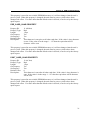
Product Description
The ET1529L is a retail terminal designed to present information to the operator and the
customer. The ET1529L is available in serial and USB versions or combo touch monitor.
The ET1529L functionally consists of a 15.0” LCD main display with a touchscreen, an
optional 12.1 inch Lcd, customer display, an optional vacuum fluorescent display (VFD)
Customer Display, an optional fingerprint reader, an optional credit card reader, and a 6
port USB (USB version only) Hub. The main display element is a 15.0 inch diagonal
XGA resolution (1024x768) LCD display. The main display will consist of an LCD
Display and touchscreen. Three types of touchscreens can be selected in the 1529L as
options. They are AccuTouch, Intellitouch, and IR. The 12.1 inch second display will
consist of the LCD Display and touchscreen(option). The Customer Display is a twenty
character two line vacuum fluorescent display (VFD). The VFD can display 40 characters in a 20 character 2 row format. Each character is made by various fonts using a 5x7
pixel format matrix.
The fingerprint reader translates illuminated images of fingerprints into digital code for
further software processing, e.g. enrollment (fingerprint registration) and verification
(authentication of registered users). The fingerprint reader uses the SEIR method and
CMOS image sensor to capture high contrast, high resolution fingerprint images. A series of algorithms extracts minutiae data from the image, mapping the distinguishing
characteristics of fingerprint ridge ends, splits, dots, and arches. To identify or verify a
fingerprint, a proprietary matching algorithm compares the extracted minutiae points
from the input fingerprint on the optical module to a previously stored sample. The
entire matching process takes roughly one second. There is a fingerprint reader available in the USB version of the ET1529L.
1-1
The credit card reader reads all three stripes on a standard credit card or drivers license.
The credit card is read by sliding the credit card, stripe side toward the display through
the credit card reader forward or backward. There is a USB credit card reader only.
The Hub provides 4 internal USB ports to be used by the credit card reader, the fingerprint reader, the touchscreen, and the customer display. The hub also supplies two USB
ports to the outside of the back of the 1529L for external use. The hub is only used by the
USB version of the 1529L. The 1529L is powered by a universal AC power source or 12
VDC from external power source.
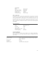
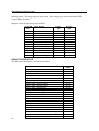
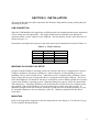
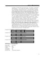
Detailed LCD Display Performance Requirements
15 inch TFT LCD Display Panel
Display Format
1024x768
Display area 15”
Pixel Pitch 15”
304.1mm(H) x 228mm(V)
0.297mm(H) x 0.297mm(V)
Contrast Ratio
Brightness
LCD
400:1 typical
350 cd/m2 (Typical)
AccuTouch
IntelliTouch
287 cd/m2 (Typical)
322 cd/m2 (Typical)
CarrollTouch
Surface Capacitive
322 cd/m2 (Typical)
322 cd/m2 (Typical)
Accutouch Transmission
82% typical
IntelliTouch Transmission
92% typical
IR Touchscreen Transmission 92% typical
Response Time
Display Color
Tr=12 msec/Tf=16msec typical
16.2 million colors, 6 Bit with dithering
Vertical Viewing Angle
Typical Vertical Viewing Angle: 60deg(looking down)/40 deg(lookingup)
@ CR>=10
Horizontal Viewing Angle
Typical Vertical Viewing Angle: 60deg(looking down)/60 deg(lookingup)
@ CR>=10d
1-2
Elo Entuitive Touchmonitor User Guide
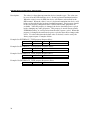
12.1 Customer Display TFT LCD Display Panel
Display Format
800x600
Display area 12.1”
Pixel Pitch 12.1”
246.0mm(H) x 184.5mm(V)
0.3075mm(H) x 0.3075mm(V)
Contrast Ratio
Brightness
150:1(Min)
180 cd/m2(Typical) with no touchscreen
IntelliTouch Transmission
165cd/m2 with IntelliTouch
92% typical
Horizontal Viewing Angle
Video Interface Connector
+/- 45 degree typical at CR=10
-30/+10 degree typical at CR=10
1-3
Customer Display
The Customer Display is a twenty character two line vacuum fluorescent display (VFD).
It consists of a VFD and VFD controller.
Serial Version
Optional Parameters
Characters per row
20
Number of rows
2
Character
5x7 dot matrix
configuration
Character Height
9.5mm
Character width
6.2mm
Character
ASCII
configuration
Character color
Blue green
MTBF
300,000 hours
Fingerprint Reader
There is a fingerprint reader in the USB version only.
General Description-FDU01B is a PC peripheral FRD (Fingerprint Recognition Device)
for USB (Universal Serial Bus) connections.
1-4
Elo Entuitive Touchmonitor User Guide
Specifications
Sensor
SecuGen FOR
Image Capture Speed
600ms/frame
Image Transfer Speed
500Byte/ms
Pixel Resolution
356x292
USB Signaling Type
Full Speed Type
Theory of Operation
The USB host initiates communication with the FDU01 using operation commands
(Sensor LED On, Fingerprint Capture Start and Stop). Fingerprint data are then captured by the CMOS sensor at a total image size of 356 x 292 with 8-bit gray level. The
image frame transfer speed is 500 bytes/ms. It takes about 600 milliseconds to send one
frame of image data over USB protocols. FDU01 uses the SecuGen FOR (Fingerprint
Optic Reader).
Sensor Specifications
Sensor
CMOS Image Sensor
Resolution
500dpi
Verifying Time
<1sec
Image Capture Error Rate
<0.1%
Life Time Typically
40,000Hrs
Credit Card Reader
There is a USB credit card reader only. The USB version is available in HID and Keyboard emulation versions. The reader reads all three stripes on a standard credit card or
drivers license.
Reference Standards-Conform to
International Standards Organization, American National Standards
applicable standards
Institute, California Drivers License, American Association of Motor
Vehicle Administrators
Message Format
Card Speed
MTBF Electronics
ACCII
3 to 50 IPS
125,000 hrs; Head 1,000,000 passes
1-5
Six Port USB Hub
The Hub provides 4 internal USB ports to be used by the credit card reader, the fingerprint reader, the touchscreen, and the customer display. The hub also supplies two USB
ports to the outside of the back of the 1529L for external use. The hub is only used by the
USB version of the 1529L. The hub meets the following requirements:
Specification
Full compliance with USB specification 1.0, 1.1 and HID Class Definition Rev 1.0.
Hub shall be self powered
Hub shall provide 2 external and 4 internal downstream ports with individual port over
current detection, protection and recovery. Supports both Open Host Controller Interface (OHCI) and Universal Host Controller Interface (UHCI).
Supports Suspend and Resume operation.
Bus fault detection and recovery.
External Power Supply
The 1529L shall be powered by a universal AC power source or 12 VDC from external
power source. The power supply shall provide the following capability:
AC power: Input voltage 85 to 265 vac
Input frequency 47 to 63hz
DC power: Input voltage 12 vdc
Input line and load regulation +/-2%
1-6
Elo Entuitive Touchmonitor User Guide
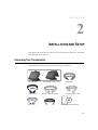
C H A P T E R
2
INSTALLATION AND SETUP
This chapter discusses how to install your LCD touchmonitor and how to install Elo
TouchSystems driver software.
Unpacking Your Touchmonitor
Check that the following items are present and in good condition:
or
Touchmonitor
Video cable
DVI cable
Touchmonitor with 12CD
Power cable US/Candian
Speaker
USB Cable
European power cable
CD and Quick Install Guide
2-7
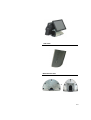
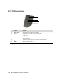
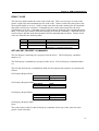
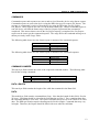
Product Overview
Main Unit
or
Rear View
2-8
Elo Entuitive Touchmonitor User Guide
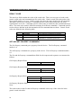
Side View
Base Bottom View
or
2-9
TM
Kensington
Lock
The KensingtonTM lock is a security device that prevents theft. To
find out more about this security device, do to http://www.
kensington.com.
2-10
Elo Entuitive Touchmonitor User Guide
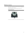
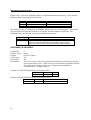
USB Interface Connection
Your touchmonitor comes with only one touchscreen connector cables: USB cable. (For
Windows 2000, Me and XP systems only.)
To set up the display, please refer to the following figures and procedures:
Remove the Cable Cover
The cables are connected at the back of the monitor.
cable cover
To remove the cover, grasp the lip of the cover and pull towards you until it snaps off.
2-11
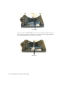
CAUTION
Before connecting the cables to your touchmonitor and PC, be sure that the
computer and touchmonitor are turned off.
NOTE
Before connecting the cables to the touchmonitor, route all the cables through
the hole in the second as shown in the pictire above.
2-12
Elo Entuitive Touchmonitor User Guide
The following illustrations guide you step by step in connecting your touchmonitor
using a USB cable connection.
Power cord
Connect one end of the power cord to the monitor and the other end to wall.
Connect the power cable to the power port in the monitor.
2-13
Video cable
Connect one end of the video cable to the rear side of computer and the other to the
LCD. Tighten by turning the two thumb screws clockwise to ensure proper grounding.
You can select DVI video cable or D-SUB15 video cable.
DVI cable
2-14
Elo Entuitive Touchmonitor User Guide
Speaker cable
Connect one end of the speaker cable to the speaker port in the computer and the other
end to the port in the monitor.
2-15
USB cable
Connect one end of the USB cable to the rear side of the computer and the other to the
LCD monitor.
The USB cable is for optional touch, MSR, CD and Finger Print Reader. Only one USB
cable is needed because the device contains a self powered USB 1.1 Hub. Two self
powered ports are available for running other USB devices. For touch only, no USB
Hub is present.
2-16
Elo Entuitive Touchmonitor User Guide
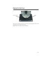
Replace the Cable Cover
Cable cover lip
cables
Then you have attached all the cables to the monitor, gently bring all the cables toward
the standard so they fit under the cover lip.
Snap the Cable cover in place over the connections.
2-17
Optimizing the LCD Display
To ensure the LCD display works well with your computer, configure the display mode
of your graphic card to make it less than or equal to 1024 x 768 resolution, and make
sure the timing of the display mode is compatible with the LCD display. Refer to Appendix A for more information about resolution. Compatible video modes for your
touchmonitor are listed in Appendix C.
Installing the Peripheral Device Drivers
Finger Print Reader
NOTE:
This driver is for MS Windows 9x through XP.
1
On the TouchTools CD, browse to Touch Monitor Peripheral s\Finger
Print Readers\driver\EasyInstall\FDP02.
2
Double-click setup.exe
Follow the Install Shield Wizard procedure to complete the installation.
For a detailed software development kit, browse to Touch Moni tor
Peripherals\Finger Print Readers and open the following files:
.
• FDxSDKforWindows1 .20.zip
.
• SecuBSPSDK for Windows2 .10.zip
You will enter one of the following serial numbers depending on your operating system:
.
• FDx SDK for Windows: 31-100s101-3586383
.
• FDx SDK for Windows CE: 32-100s101-9713291
.
• SecuBSP SDK for Windows: 41-100s101-7685871
.
• SecuBSP SDK for Windows CE: 42-100s101-1155462
.
• SecuBSP SDK: 51-100s101-5963137
Once the driver setup is complete, the demo program can be run from Touch Moni tor
Peripherals\Finger Print Readers\FPR Demo\BSPDemo.exe
2-18
Elo Entuitive Touchmonitor User Guide
Magnetic Stripe Reader
No device are needed.
Testing the USB MSR Keyboard Emulation
1 Plug in the device.
2 Open MS Word.
3 Slide the card through the MSR to view the data.
Testing the USB-HID Class MSR
1 On the CD, browse to Touch Monitor Peripherals\Magnetic Stripe Card
Readers\Demo.
2 Open the Readme.txt and follow instructions to test the unit.
Convert MSR from HID to keyboard emulation
MSR Convertion:
Get program @ http://www.magtek.com/support/software/demo_programs/usb_swipe_insert_reader.asp
1. To convert from HID to Keyboard Emul ation Mode.
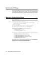
1.1
Double click on HID MSR Icon in desktop.
The following window will appear
1.2
Click on About to verify version
1.3
Close About Dialog box.
1.4
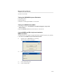
Click on Read Cards…
2-19
1.5
This dialog will appear
1.6 Swipe Test card.
2-20
1.7
Close Read Cards Dialog.
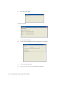
1.8
Click on Send Command. The following dialog box will appear
1.9
To send Inquiry MSR type
1.10
Type 00 10 into area under the heading Message(Hex)
Elo Entuitive Touchmonitor User Guide
1.11
Then click on Send Message.
1.12
The DATA=00 means it’s USB HID.
1.13
Switch to Keyboard Emulation
1.14
Type 01 10 01 into area under the heading Message(Hex)
1.15
Then click on Send Message.
1.16
Send Inquiry MSR type
1.17
Type 00 10 into area under the heading Message(Hex)
1.18
Then click on Send Message.
2-21
1.19
The DATA=01 means it’s USB Keyboard Emulation.
1.20
You must now reset the MSR by sending the command 02.
1.21
Type 02 into area under the heading Message(Hex)
1.22
Then click on Send Message.
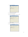
1.23
Double click on The KB MSR Test icon in the desktop and slide the test c card.
The following icon will appear
1.24 Done.
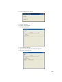
Convert MSR from keyboard emulation to HID
MSR Convertion:
Get program @ http://www.magtek.com/support/software/demo_programs/usb_swipe_insert_reader.asp
1.
To convert from Keyboard Emulation to HID Mode.
1.1
Double click on HID MSR Icon in desktop.
The following window will appear
2-22
Elo Entuitive Touchmonitor User Guide
1.2 click on About to verify version
1.3 Close About Dialog.
1.4 Click on Send Commands
1.5 This Dialog will appear.
1.6 To send Inquiry MSR type
1.7 Type 00 10 into area under the heading Message(Hex)
1.8 Then click on Send Message.
2-23
2-24
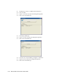
1.9
The DATA=01 means it’s USB Keyboard Emulation.
1.10
Switch to HID
1.11
Type 01 10 00 into area under the heading Message(Hex)
1.12
Then click on Send Message.
1.13
Send Inquiry MSR type
1.14
Type 00 10 into area under the heading Message(Hex)
1.15
Then click on Send Message.
1.16
You must now reset the MSR by sending the command 02.
1.17
Type 02 into area under the heading Message(Hex)
1.18
Then click on Send Message.
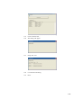
Elo Entuitive Touchmonitor User Guide
1.19
Click on Read Cards…
1.20
This dialog will appear
1.21
Swipe Test card.
1.22
Cose Read Cards Dialog.
1.23
Done.
2-25
Rear Facing Customer Display
USB Customer Display
Plug in the USB cable attached to the Customer Display unit. The New Hardware Wizard dialog box will appear.
1 Choose Next and select “Search for the best driver for your device (Recommended)
” then choose Next.
2 When a list of search locations is displayed, place a checkmark on the drive contain
ing the driver package:
Touch Monitor Peripherals\Rear Facing Customer Displays\Drivers\xxx\LCLD9.sys,
where xxx is Win98 for a Windows 98 based system or 2000 for a Windows XP/2000
based system.
3 Insert the disk into your drive. (If the driver files have been copied to your hard drive
or have been distributed on CD, place a checkmark on “Specify a location” and browse
to select the directory containing the driver files.)
4 Choose Next. Once the Customer Display driver has been detected choose Next again.
5 Wait while driver files are copied to your computer.
6 Insert your Windows CD if prompted and choose Finish
2-26 Elo Entuitive Touchmonitor User Guide
To test the drivers:
1 In windows click on Start > Run
2 Enter “cmd” > OK
3 Type “ECHO ELO>\.\LCLD9\” > Enter
The display will show ELO.
Installing the Touch Driver Software
Elo TouchSystems provides driver software that allows your touchmonitor to work with
your computer. Drivers are located on the enclosed CD-ROM for the following operating systems:
• Windows XP
• Windows 2000
• Windows Me
• Windows 98
• Windows 95
• Windows NT 4.0
• CE 2.x, 3.0, 4x
• Windows XP Embedded
• Windows 3.x
•MS DOS
•OS/2
Additional drivers and driver information for other operating systems (including
Macintosh and Linux) are available on the Elo TouchSystems web site at www.elotouch.
com.
Your Elo USB touchmonitor is plug-and-play compliant. Information on the video capabilities of your touchmonitor is sent to your video display adapter when Windows starts.
If Windows detects your touchmonitor, follow the instructions on the screen to install a
generic plug-and-play monitor.
Refer to the appropriate following section for driver installation instructions.
2-27
Installing the USB Touch Driver
Installing the USB Touch Driver for Windows XP, Windows 2000,
Me and 98
1 Insert the Elo CD-ROM in your computer’s CD-ROM drive.
If Windows XP, Windows 2000,Windows 98, or Windows Me starts the Add New
Hardware Wizard:
2 Choose Next. Select “Search for the best driver for your device (Recommended)” and
choose Next.
3 When a list of search locations is displayed, place a checkmark on “Specify a
location” and use Browse to select the \EloUSB directory on the Elo CD-ROM.
4 Choose Next. Once the Elo TouchSystems USB touchscreen driver has been detected,
choose Next again.
5 You will see several files being copied. Insert your Windows 98 CD if prompted.
Choose Finish.
If Windows XP, Windows 2000,Windows 98, or Windows Me does not start the Add
New Hardware Wizard:
NOTE:
For Windows XP and Windows 2000 you must have administrator access
rights to install the driver.
1 Insert the Elo CD-ROM in your computer’s CD-ROM drive. If the AutoStart feature
for your CD-ROM drive is active, the system automatically detects the CD and starts
the setup program.
2 Follow the directions on the screen to complete the driver setup for your
version of Windows. If the AutoStart feature is not active:
1
Click Start > Run.
2
Click the Browse button to locate the EloCd.exe program on the CD-ROM.
3
Click Open, then OK to run EloCd.exe.
4
Follow the directions on the screen to complete the driver setup for your
version of Windows.
2-28
Elo Entuitive Touchmonitor User Guide
C H A P T E R
3
OPERATION
About Touchmonitor Adjustments
Your touchmonitor will unlikely require adjustment. Variations in video output and application may require adjustments to your touchmonitor to optimize the quality of the
display.
For best performance, your touchmonitor should be operating in native resolution, that
is 1024x768 at 60-75 Hz. Use the Display control panel in Windows to choose 1024x768
resolution.
Operating in other resolutions will degrade video performance. For further information,
please refer to Appendix A.
All adjustments you make to the controls are automatically memorized. This feature
saves you from having to reset your choices every time you unplug or power your
touchmonitor off and on. If there is a power failure your touchmonitor settings will not
default to the factory specifications.
To restore factory set up, choose it from the OSD. See page 3-25.
3-29
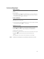
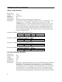
15.0” LCD Function Key
5
4
3
2
1
1
2
Controls
Power Switch
Select
Function
Turns the display system power on or off.
Displays the OSD menus on the screen and used to
select (“Clockwise” and “Counter-clockwise” direction) the OSD control options
on the screen.
3
4
5
3-30
Adjusts the decreasing value of the selected
OSD control option.
Menu
Adjusts the increasing value of the selected OSD control option.
Menu display and menu exit.
Elo Entuitive Touchmonitor User Guide
Controls and Adjustment
OSD Lock/Unlock
You are able to lock and unlock the OSD feature. The monitor is shipped in the unlocked
position.
To lock the OSD:
1 Press the Menu button and
button simultaneously for 2 seconds. A window will
appear displaying “OSD Unlock”. Continue to hold the buttons down for another 2
seconds and the window toggles to “OSD Lock”.
Power Lock/Unlock
You are able to lock/unlock the Power feature. The monitor is shipped in the
unlockedposition.To lock the power:
1 Press the Menu button and the
simultaneously for 2 seconds. A window for another
2 seconds and the window toggles to — Power Lock“.
OSD Menu Functions
To display the OSD Menu press the Menu button.
1 Press the
button or
button to select the different OSD control option.
2 When the function you want to change is displayed, press the Select button.
To adjust the Value of the function:
1 Pressing the
2 Pressing the
button increases the value of the selected OSD control option.
button decreases the value of the selected OSD control
option.
After adjusting the values, the monitor will automatically save the changes.
NOTE:
The OSD screen will disappear if no input activities are detected for 45 seconds.
3-31
OSD Control Options
Brightness
• Background Luminance of the LCD panel is adjusted.
Contrast
•Adjusts the contrast or the values of color gain (RED, GREEN or BLUE).
Saturation, Hue, Flesh Tones
•Adjusts the color intensity and tint so faces appear natural.
Phase
•Adjusts the phase of the dot clock.
Auto Adjust
• Clock system auto adjustment (under 5 seconds).
OSD Left/Right
• The OSD screen is moved vertically right and left.
OSD Up/Down
• The OSD screen is moved vertically up and down.
Clock
•Adjusts the ratio of dividing frequency of the dot clock.
Color Temperature
• Sets R, G, B gain.
Current Input
• The video signal from Analog or Digital under the input is indicated.
OSD Position
•Allows the OSD indication position to be selected.
3-32
Elo Entuitive Touchmonitor User Guide
Language
• Languages used for OSD menu display: English, French, German, Spanish and
Japanese.
Recall Defaults
• Recalls the factory OSD default settings.
OSD Timeout
•Adjusts the amount of time in which the OSD will disappear.
Power-Save (No Input)
• The LCD panel background is cut when there is no signal input (AC line power
consumption of 4w or less).
Power LED Display & Power Saving
General Power Saving Mode
When the power switch are switch on, this LED lights in green.
The LED indicates the different power status with altered LED colors when monitor
operates in different modes (see following table).
Power
Mode
Consumption
Indicator
On
50w max.
Green
Sleep
4w max.
Orange
Off
2w
NO
We recommend switching the monitor off when it is not in use for a long period of time.
Display Angle
For viewing clarity, you can tilt the LCD forward up 67 to 90 degrees.
3-33
CAUTION
In order to protect the LCD, be sure to hold the base when adjusting the LCD,
and take care not to touch the screen.
3-34
Elo Entuitive Touchmonitor User Guide
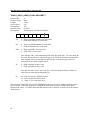
12.1” LCD Function Key
4
3
2
1
1
Controls
Select
Function
Displays the OSD menus on the screen and used to
select (“Clockwise” and “Counter-clockwise” direction) the OSD control options
2
on the screen.
Adjusts the decreasing value of the selected
3
OSD control option.
Adjusts the increasing value of the selected OSD control option.
4
Menu
Menu display and menu exit.
3-35
Controls and Adjustment
OSD Lock/Unlock
You are able to lock and unlock the OSD feature. The monitor is shipped in the unlocked
position.
To lock the OSD:
1 Press the Menu button and
button simultaneously for 2 seconds. A window will
appear displaying “OSD Unlock”. Continue to hold the buttons down for another 2
seconds and the window toggles to “OSD Lock”.
Power Lock/Unlock
You are able to lock/unlock the Power feature. The monitor is shipped in the
unlockedposition.To lock the power:
1 Press the Menu button and the
simultaneously for 2 seconds. A window for another
2 seconds and the window toggles to — Power Lock“.
OSD Menu Functions
To display the OSD Menu press the Menu button.
1 Press the
button or
button to select the different OSD control option.
2 When the function you want to change is displayed, press the Select button.
To adjust the Value of the function:
1 Pressing the
2 Pressing the
button increases the value of the selected OSD control option.
button decreases the value of the selected OSD control
option.
After adjusting the values, the monitor will automatically save the changes.
NOTE:
3-36
The OSD screen will disappear if no input activities are detected for 45 seconds.
Elo Entuitive Touchmonitor User Guide
OSD Control Options
Brightness
• Background Luminance of the LCD panel is adjusted
Contrast
• Gain of R, G, and B signal is adjusted.
Phase
• The phase of the dot clock is adjusted.
Auto Adjust
• Automatically adjusts the systems dot clock(takes approximately 5 seconds).
OSD Left/Right
• The osd screen is moved horizontally left and right.
OSD Up/Down
• The OSD screen is moved vertically up and down.
Clock
• The ratio of dividing frequency of the dot clock is adjusted.
Color Temperature
• Sets the R, G, and B gains.
Information
• The frequency of the horizontal/vertical synchronizing signal under the input is
indicated.
YUV
• Saturation, Hue, Flesh Tones: Adjusts colors intensity so face appears natural.
OSD Position
• The osd indication position can be selected.
3-37
Language
• Select the language used for the OSD menu from among English, French,
Deutsch, Spanish, and Japanese.
Recall Defaults
• Restore all original factory defaults.
OSD Timeout
• Adjust how long the OSD menu is displayed.
OSD Exit
• Exit’s the OSD menu.
3-38
Elo Entuitive Touchmonitor User Guide
C H A P T E R
4
TROUBLESHOOTING
If you are experiencing trouble with your touchmonitor, refer to the following table. If
the problem persists, please contact your local dealer or our service center. Elo Technical Support numbers are listed on the last page of this manual.
Solutions to Common Problems
Problem
Sug gest i on( s)
The monitor does not respond after
you turn on the system.
Check that the monitor’s Power Switch is on.
Turn off the power and check the monitor’s power cord and signal
cable for proper connection.
Characters on the screen are dim
The screen is blank
Refer to the Controls and Adjustments section to adjust the brightness.
During operation, the monitor screen may automatically turn off as a
result of the Power Saving feature. Press any key to see if the screen
reappears.
Refer to the Controls and Adjustments section to adjust the brightness.
OSD or power buttons don’t work
“Out of Range” display
Check to see that they are not locked out. See page 3-33.
check to see of the resolution or vertical frequency of your computer is
higher than that of the LCD display.
Reconfigure the resolution of your computer to make it less than or
Touch doesn’t work
equal to 1024x768. 1024x768 is optimal. See Appendix A for more
information on resolution.
Make sure cable is securely attached at both ends.
4-39
4-40 Elo Entuitive Touchmonitor User Guide
C H A P T E R
A
NATIVE RESOLUTION
The native resolution of a monitor is the resolution level at which the LCD panel is
designed to perform best. For the Elo LCD touchmonitor, the native resolution is 1024
x 768 for the 15.0 inch size. In almost all cases, screen images look best when viewed at
their native resolution. You can lower the resolution setting of a monitor but not increase
it.
Input Video
15.0" LCD
640x480 (VGA)
800x600 (SVGA)
Transforms input format to 1024x768
Transforms input format to 1024x768
1024x768(XGA)
Display in Native Resolution
The native resolution of an LCD is the actual number of pixels horizontally in the LCD
by the number of pixels vertically in the LCD. LCD resolution is usually represented by
the following symbols:
VGA
640x480
SVGA
XGA
800x600
1024x768
A-41
As an example, a SVGA resolution LCD panel has 800 pixels horizontally by 600 pixels
vertically. Input video is also represented by the same terms. XGA input video has a
format of 1024 pixels horizontally by 768 pixels vertically. When the input pixels contained in the video input format match the native resolution of the panel, there is a one to
one correspondence of mapping of input video pixels to LCD pixels. As an example, the
pixel in column 45 and row 26 of the input video is in column 45 and row 26 of the
LCD. For the case when the input video is at a lower or higher resolution than the native
resolution of the LCD, the direct correspondence between the video pixels and the LCD
pixels is lost. The LCD controller can compute the correspondence between video pixels and LCD pixels using algorithms contained on its controller. The accuracy of the
algorithms determines the fidelity of conversion of video pixels to LCD pixels. Poor
fidelity conversion can result in artifacts in the LCD displayed image such as varying
width characters.
A-42
Elo Entuitive Touchmonitor User Guide
C H A P T E R
B
TOUCHMONITOR SAFETY
This manual contains information that is important for the proper setup and maintenance
of your touchmonitor. Before setting up and powering on your new touchmonitor, read
through this manual, especially Chapter 2 (Installation), and Chapter 3 (Operation).
1 To reduce the risk of electric shock, follow all safety notices and never open the
touchmonitor case.
2 Turn off the product before cleaning
3 Your new touchmonitor is equipped with a 3-wire, grounding power cord. The power
cord plug will only fit into a grounded outlet. Do not attempt to fit the plug into an
outlet that has not been configured for this purpose. Do not use a damaged power
cord. Use only the power cord that comes with your Elo TouchSystems Touchmonitor.
Use of an unauthorized power cord may invalidate your warranty.
4 The slots located on the sides and top of the touchmonitor case are for ventilation. Do
not block or insert anything inside the ventilation slots.
5 It is important that your touchmonitor remains dry. Do not pour liquid into or onto
your touchmonitor. If your touchmonitor becomes wet do not attempt to repair it
yourself.
B-43
Care and Handling of Your Touchmonitor
The following tips will help keep your Elo Entuitive touchmonitor functioning at the
optimal level.
• To avoid risk of electric shock, do not disassemble the brick supply or display unit
cabinet. The unit is not user serviceable. Remember to unplug the display unit from
the power outlet before cleaning.
•Do not use alcohol (methyl, ethyl or isopropyl) or any strong dissolvent. Do not use
thinner or benzene, abrasive cleaners or compressed air.
• To clean the display unit cabinet, use a cloth lightly dampened with a mild detergent.
•Avoid getting liquids inside your touchmonitor. If liquid does get inside, have a
qualified service technician check it before you power it on again.
•Do not wipe the screen with a cloth or sponge that could scratch the surface.
• To clean the touchscreen, use window or glass cleaner. Put the cleaner on the rag and
wipe the touchscreen. Never apply the cleaner directly on the touchscreen .
B-44
Elo Entuitive Touchmonitor User Guide
C H A P T E R
C
TECHNICAL SPECIFICATIONS
Display Modes
Your Elo Entuitive touchmonitor is compatible with the following standard
video modes:
Item
1
Resolution
640X350
Type
VGA
H. Scan(KHz)
31.469
V. Scan(Hz)
70.087
Pol.
+/
2
3
4
720X400
640X480
640X480
VGA
VGA
VESA72
31.469
31.469
37.861
70.087
59.940
72.809
-/+
-/
-/
5
6
640X480
800X600
VESA75
SVGA
37.500
35.156
75.000
56.250
-/
+/+
7
8
800X600
800X600
SVGA
VESA72
37.879
48.077
60.317
72.188
+/+
+/+
9
10
11
800X600
1024X768
1024X768
VESA75
XGA
XGA
46.875
48.363
56.476
75.000
60.004
70.069
+/+
-/-/-
12
1024X768
VESA75
60.023
75.029
+/+
C-45
Touchmonitor Specifications
Model
ET1529L
LCD Display
Display Size
15.0” TFT Active Matrix Panel
304.1(H) x 228(V) mm
Pixel Pitch
Display Mode
0.297(H) x 0.297(V) mm
VGA 640 x 350 (70 Hz)
VGA 720 x 400 (70 Hz)
VGA 640 x 480 (60 / 72 / 75 Hz)
SVGA 800 x 600 (56 / 60 / 72 / 75Hz)
Native
XGA 1024 x 768 (60 / 70 / 75Hz)
XGA 1024 x 768
Contrast Ratio
Brightness
LCD
400 : 1 (typical)
350 cd/m2 with AT 287 cd/m2, IT 322 cd/m2, IR 322 cd/m2
350 cd/m2 (Typical)
AccuTouch
IntelliTouch
287 cd/m2 (Typical)
322 cd/m2 (Typical)
CarrollTouch
Surface Capacitive
322 cd/m2 (Typical)
322 cd/m2 (Typical)
Response Time
Display Color
Tr= 12 msec, Tf= 16 mesc typical
16.2 million color, 6 bit with dithering
Viewing Angle
Input Signal
(L/R)= -60o/+60o (typical), (U/D) -60o/+40o (typical)
R.G.B. Analog 0.7V peak to peak
TTL Positive or Negative, Composite Sync, Sync on green
VGA Analog Video
Sync
Signal Connector
DVI Video
Digital TMDS Input
15 Pin D-Sub, DVI-D
Front Control
OSD
Power on / off , Menu,
,
, Select
Contrast, Brightness, H/V-Position, Recall default,
Color Temperature, Volume, Saturation, Hue, Flash Tone,
Phase, Clock OSD H/V position, OSD Time, Auto Adjust,
OSD Language, Input Select
Plug & Play
Touch Panel (optional)
DDC1 / 2B
AccuTouch, IntelliTouch and CarrollTouch, Surface Capacitive
Power
Operating Conditions
Input: AC 85-265V, 47-63Hz, or DC 12V/4A (max.)
0oC ~ 40oC (41oF ~ 95oF)
Temp
Humidity
Dimensions (HxWxD)
Weight (Net)
Certifications
C-46
20% ~ 80% (No Condensation)
Altitude To 12,000 Feet
354 x 301 x 285mm
20.1lbs., monitor weight 16.2 lbs.
UL, C-UL, FCC-A, CE, TUV-GS, VCCI, MPRII, C-TICK
Elo Entuitive Touchmonitor User Guide
AccuTouch Touchscreen Specifications
Mechanical
Construction
Top: Polyester with outside hard- surface coating with clear or
antiglare finish.
Inside: Transparent conductive coating.
Bottom: Glass substrate with uniform resistive coating. Top and
bottom layers separated by Elo-patented separator dots.
Positional Accuracy
Touchpoint Density
Standard deviation of error is less than 0.080 in. (2.03 mm). This
equates to less than ±1%.
More than 100,000 touchpoints/in² (15,500 touchpoints/cm²).
Touch Activation Force
Surface Durability
Typically less than 4 ounces (113 grams).
Meets Taber Abrasion Test (ASTM D1044), CS-10F wheel, 500 g.
Expected Life
Meets pencil hardness 3H.
AccuTouch technology has been operationally tested to greater than
Performance
Optical
Light Transmission
(per ASTM D1003)
Visual Resolution
35 million touches in one location without failure, using a stylus
similar to a finger.
Typically 85% at 550-nm wavelength (visible light spectrum).
All measurements made using USAF 1951 Resolution Chart, under
30 X magnification, with test unit located approximately 1.5 in.
(38 mm) from surface of resolution chart.
Antiglare surface: 6:1 minimum.
Haze (per ASTM D1003)
Gloss (per ASTM D2457)
Antiglare surface: Less than 15%.
Antiglare surface: 90 ± 20 gloss units tested on a hard-coated front
surface.
C-47
IntelliTouch Touchscreen Specifications
Mechanical
Positional Accuracy
Standard deviation of error is less than 0.080 in. (2.03 mm).
Equates to less than ±1%.
Touchpoint Density
Touch Activation Force
Surface Durability
More than 100,000 touchpoints/in2 (15,500 touchpoints/cm2).
Typically less than 3 ounces (85 grams).
Surface durability is that of glass, Mohs’ hardness rating of 7.
Expected Life Performance
No known wear-out mechanism, as there are no layers, coatings,
or moving parts. IntelliTouch technology has been operationally
tested to more than 50 million touches in one location without
failure, using a stylus similar to a finger.
Sealing
Optical
Light Transmis sion (per ASTM
D1003)
Visual Resolution
Unit is sealed to protect against splashed liquids, dirt, and dust.
90%
All measurements made using USAF 1951 Resolution Chart,
under 30X magnification, with test unit located approximately
1.5 in (38 mm) from surface of resolution chart.
Clear surface: Excellent, with no noticeable degradation.
Antiglare surface: 6:1 minimum.
Gloss (per ASTM D2457
using a 60-degree gloss meter)
Environmental
Chemical Resistance
Antiglare surface: Curved: 60 ± 20 gloss units or 75 ± 15 gloss
units.
The active area of the touchscreen is resistant to all chemicals
that do not affect glass, such as:
Acetone
Toluene
Methyl ethyl ketone
Isopropyl alcohol
Methyl alcohol
Ethyl acetate
Ammonia-based glass cleaners
Gasoline
Kerosene
Vinegar
Electrostatic Protection (per
EN 61 000-4-2, 1995)
Meets Levels 4 (15kV air/8 kV contact discharge)
C-48 Elo Entuitive Touchmonitor User Guide
Infrared Touchscreen Specifications
Mechanical
Input Method
Electrical
Input Method Finger or gloved hand activation
Positional Accuracy
Resolution
Typical centroid accuracy: 2 mm with 1 mm STD error
Touchpoint density is based on controller resolution of 4096 x
4096
Touch Activation Force
Controller
No minimum touch activation force is required
Board: Serial (RS232) or USB 1.1
Optical
Light Transmission
Glass overlay: 90% per ASTM D1003-92
Chemical Resistance
Environmental
Glass overlays: The touch active area of the touchscreen is
resistant to chemicals that do not affect glass, such as: acetone,
toluene, methyl ethyl ketone, isopropyl alcohol, methyl alcohol,
ethyl acetate, ammonia-based glass cleaners, gasoline, kerosene,
vinegar. Polycarbonate bezel: around perimeter of display has
some sensitivity to hydrocarbons.
Durability
Surface Durability
Glass filter option: Surface durability is that of glass, Mohs’
hardness rating of 7.
C-49
15” LCD Touchmonitor(ET1529L-XXXA-1-XX) Dimensions
15” LCD Touchmonitor(ET1529L-XXXA-1-C3/C4-X) Dimensions
15” LCD Touchmonitor(ET1529L-XXXA-1-XX-T) Dimensions
C-50
Elo Entuitive Touchmonitor User Guide
REGULATORY INFORMATION
I. Electrical Safety Information:
A) Compliance is required with respect to the voltage, frequency, and current requirements indicated on the manufacturer’s label. Connection to a different power source
than those specified herein will likely result in improper operation, damage to the equipment or pose a fire hazard if the limitations are not followed.
B) There are no operator serviceable parts inside this equipment. There are hazardous
voltages generated by this equipment which constitute a safety hazard. Service should
be provided only by a qualified service technician.
C) This equipment is provided with a detachable power cord which has an integral safety
ground wire intended for connection to a grounded safety outlet.
1) Do not substitute the cord with other than the provided approved type. Under
no circumstances use an adapter plug to connect to a 2-wire outlet as this will
defeat the continuity of the grounding wire.
2) The equipment requires the use of the ground wire as a part of the safety
certification, modification or misuse can provide a shock hazard that can result
in serious injury or death.
3) Contact a qualified electrician or the manufacturer if there are questions about
the installation prior to connecting the equipment to mains power.
II. Emissions and Immunity Information
A) Notice to Users in the United States: This equipment has been tested and found to
comply with the limits for a Class B digital device, pursuant to Part 15 of FCC Rules.
These limits are designed to provide reasonable protection against harmful interference
in a residential installation. This equipment generates, uses, and can radiate radio frequency energy, and if not installed and used in accordance with the instructions, may
cause harmful interference to radio communications.
B) Notice to Users in Canada: This equipment complies with the Class B limits for radio
noise emissions from digital apparatus as established by the Radio Interference Regulations of Industrie Canada.
C) Notice to Users in the European Union: Use only the provided power cords and
interconnecting cabling provided with the equipment. Substitution of provided cords
and cabling may compromise electrical safety or CE Mark Certification for emissions or
immunity as required by the following standards:
51
This Information Technology Equipment (ITE) is required to have a CE Mark on
the manufacturer’s label which means that the equipment has been tested to the
following Directives and Standards:
This equipment has been tested to the requirements for the CE Mark as required
by EMC Directive 89/336/EEC indicated in European Standard EN 55 022 Class
B and the Low Voltage Directive 73/23/EEC as indicated in European Standard
EN 60 950.
D) General Information to all Users: This equipment generates, uses and can radiate
radio frequency energy. If not installed and used according to this manual the equipment
may cause interference with radio and television communications. There is, however, no
guarantee that interference will not occur in any particular installation due to site-specific factors.
1) In order to meet emission and immunity requirements, the user must observe
the following:
a) Use only the provided I/O cables to connect this digital device with any
computer.
b) To ensure compliance, use only the provided manufacturer’s approved
line cord.
c) The user is cautioned that changes or modifications to the equipment
not expressly approved by the party responsible for compliance could
void the user’s authority to operate the equipment.
2) If this equipment appears to cause interference with radio or television reception, or
any other device:
a) Verify as an emission source by turning the equipment off and on.
b) If you determine that this equipment is causing the interference, try to
correct the interference by using one or more of the following measures:
i) Move the digital device away from the affected receiver.
ii) Reposition (turn) the digital device with respect to the affected
receiver.
iii) Reorient the affected receiver’s antenna.
iv) Plug the digital device into a different AC outlet so the digital
device and the receiver are on different branch circuits.
v) Disconnect and remove any I/O cables that the digital device
does not use. (Unterminated I/O cables are a potential source of
high RF emission levels.)
vi) Plug the digital device into only a grounded outlet receptacle.
Do not use AC adapter plugs. (Removing or cutting the line cord
ground may increase RF emission levels and may also present a
lethal shock hazard to the user.)
If you need additional help, consult your dealer, manufacturer, or an experienced radio
or television technician.
52
Elo Entuitive Touchmonitor User Guide
"The application of this monitor is restricted to special controlled luminous environments.The screen surface trend to
reflect annoying light of lamps and sunlight. To avoid these reflections the monitor should not be positioned in front of a
window or directed to luminaries. The monitor is in compliance with Reflection Class III according to ISO
13406-2"
"Die Anwendung dieses Bildschirms ist auf speziel kontrollierte
Umgebungsbeleuchtungen eingeschränkt. Die Bildschirmoberfläche neigt zu störenden Spielungen von Lampen und
Sonnenlicht. Um diese Refelxionen zu vermeiden sollte der Monitor nicht auf Fenster und Beleuchtungseinrichtungen
ausgerichtet sein. Der Monitor erfüllt nur die Relexionsklasse III nach ISO 13406-2"
This class B digital apparatus meets all requirements of the Canadian Interference-Causing Equipment Regulations.
Cet appareil numérique de la classe B respecte toutes les exigences du Règlement sur le matériel brouilleur du Canada.
This device complies with Part 15 of the FCC Rules. Operation is subject to the following two conditions: (1) This device
may not cause harmful interference, and (2) This device must accept any interference reveived, including interference that
may cause undesired operation.
CAUTION:
Danger of explosion if battery is incorrectly replaced. Replace only with the same or equivalent type recommended by
the manufacturer. Dispose of used batteries according to the manufacturer’s instructions.
VORSICHT:
Explosionsgetahr bei unsachgemäßen Austausch der Batterie. Ersatz nur durch denselben oder einem vom Hersteller
empfohlenem ähnljchen Typ. Entsorgung gebrauchter Batterien nach Angaben des Herstellers.
53
54
Elo Entuitive Touchmonitor User Guide
WARRANTY
Except as otherwise stated herein or in an order acknowledgment delivered to Buyer,
Seller warrants to Buyer that the Product shall be free of defects in materials and
workmanship. With the exception of the negotiated warranty periods; the warranty for
the touchmonitor and components of the product is 3 years.
Seller makes no warranty regarding the model life of components. Seller’s suppliers
may at any time and from time to time make changes in the components delivered as
Products or components.
Buyer shall notify Seller in writing promptly (and in no case later than thirty
(30) days after discovery) of the failure of any Product to conform to the warranty set
forth above; shall describe in commercially reasonable detail in such notice the symptoms associated with such failure; and shall provide to Seller the opportunity to inspect
such Products as installed, if possible. The notice must be received by Seller during the
Warranty Period for such product, unless otherwise directed in writing by the Seller.
Within thirty (30) days after submitting such notice, Buyer shall package the allegedly
defective Product in its original shipping carton(s) or a functional equivalent and shall
ship to Seller at Buyer’s expense and risk.
Within a reasonable time after receipt of the allegedly defective Product and verification
by Seller that the Product fails to meet the warranty set forth above, Seller shall correct
such failure by, at Seller’s options, either (i) modifying or repairing the Product or (ii)
replacing the Product. Such modification, repair, or replacement and the return shipment of the Product with minimum insurance to Buyer shall be at Seller’s expense.
Buyer shall bear the risk of loss or damage in transit, and may insure the Product. Buyer
shall reimburse Seller for transportation cost incurred for Product returned but not found
by Seller to be defective. Modification or repair, of Products may, at Seller’s option,
take place either at Seller’s facilities or at Buyer’s premises. If Seller is unable to modify,
repair, or replace a Product to conform to the warranty set forth above, then Seller shall,
at Seller’s option, either refund to Buyer or credit to Buyer’s account the purchase price
of the Product less depreciation calculated on a straight-line basis over Seller’s stated
Warranty Period.
55
THESE REMEDIES SHALL BE THE BUYER’S EXCLUSIVE REMEDIES FOR
BREACH OF WARRANTY. EXCEPT FOR THE EXPRESS WARRANTY SET
FORTH ABOVE, SELLER GRANTS NO OTHER WARRANTIES, EXPRESS OR
IMPLIED BY STATUTE OR OTHERWISE, REGARDING THE PRODUCTS, THEIR
FITNESS FOR ANY PURPOSE, THEIR QUALITY, THEIR MERCHANTABILITY,
THEIR NONINFRINGEMENT, OR OTHERWISE. NO EMPLOYEE OF SELLER
OR ANY OTHER PARTY IS AUTHORIZED TO MAKE ANY WARRANTY FOR
THE GOODS OTHER THAN THE WARRANTY SET FORTH HEREIN. SELLER’S
LIABILITY UNDER THE WARRANTY SHALL BE LIMITED TO A REFUND OF
THE PURCHASE PRICE OF THE PRODUCT. IN NO EVENT SHALL SELLER BE
LIABLE FOR THE COST OF PROCUREMENT OR INSTALLATION OF SUBSTITU TE GO OD S BY BU YER O R FOR ANY SP ECIAL, CON SEQU ENTIAL,
INDIRECT, OR INCIDENTAL DAMAGES.
Buyer assumes the risk and agrees to indemnify Seller against and hold Seller harmless
from all liability relating to (i) assessing the suitability for Buyer’s intended use of the
Products and of any system design or drawing and (ii) determining the compliance of
Buyer’s use of the Products with applicable laws, regulations, codes, and standards.
Buyer retains and accepts full responsibility for all warranty and other claims relating to
or arising from Buyer’s products, which include or incorporate Products or components
manufactured or supplied by Seller. Buyer is solely responsible for any and all representations and warranties regarding the Products made or authorized by Buyer. Buyer will
indemnify Seller and hold Seller harmless from any liability, claims, loss, cost, or expenses (including reasonable attorney’s fees) attributable to Buyer’s products or representations or warranties concerning same.
56
Elo Entuitive Touchmonitor User Guide
INDEX
Numerics
F
15.0" LCD Touchmonitor (ET1529L-XXWA-1)
Dimensions, 50
Finger Print Reader, 4
A
About Touchmonitor Adjustments, 29
AccuTouch Touchscreen Specifications, 47
Auto Adjust, 32
G
General Power Saving Mode, 33
Gloss, AccuTouch, 47
Gloss, IntelliTouch, 48
Mechanical, AccuTouch, 47
Mechanical, IntelliTouch, 48
B
Base Bottom View, 9
Brightness, 32
C
Care and Handling of Your Touchmonitor, 44
Chemical Resistance, IntelliTouch, 48
Chemical Resistance, IR, 49
Cleaning Your Touchmonitor, 44
Clock, 32,36
Color Temperature, 32,36
Construction, AccuTouch, 47
Contrast, 32,36
Controller, IR, 49
Controls and Adjustment, 31,35
Credit Card Reader, 5
Current Input, 32,36
Customer Display, 4
D
Detailed LCD Display Performance Requirements, 2
Display Angle, 33
Display Modes, 45
Durability, IR, 49
E
Electrical Safety Information, 51
Electrical, IR, 49
Electrostatic Protection, IntelliTouch, 48
Emissions and Immunity Information, 51
Environmental, 48
Environmental, IR, 49
Expected Life Performance, AccuTouch, 47
Expected Life Performance, IntelliTouch, 48
External 12 VDC Power Supply, 6
H
Haze, AccuTouch, 47
I
Infrared Touchscreen Specifications, 49
Input Method, 49
Installation and Setup, 7
Installing the Peripheral Device Drivers, 18
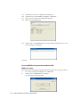
Installing the Touch Driver Software, 27
Installing the USB Touch Driver, 28
Installing the USB Touch Driver for Windows XP,
Windows 2000, Me and 98, 28
IntelliTouch Touchscreen Specifications, 48
K
Kensington™ Lock, 10
L
Language, 33
Light Transmission, AccuTouch, 47
Light Transmission, IntelliTouch, 48
Light Transmission, IR, 49
M
Magnetic Stripe Reader, 19
Main Unit, 8
Mechanical, 41
I N D E X - 57
N
T
Native Resolution, 41
Technical Specifications, 45
Testing the USB MSR Keyboard Emulation, 19
Testing the USB-HID Class MSR, 19
Theory of Operation, 4
Touch Activation Force, AccuTouch, 47
Touch Activation Force, IntelliTouch, 48
Touch not working, 39
Touchmonitor Safety, 43
Touchmonitor Specifications, 46
Touchpoint Density, AccuTouch, 47
Touchpoint Density, IntelliTouch, 48
Troubleshooting, 39
O
Optical, AccuTouch, 47
Optical, IntelliTouch, 48
Optical, IR, 49
Optimizing the LCD Display, 18
OSD Control Options, 32,36
OSD Left/Right, 32,36
OSD Lock/Unlock, 31,35
OSD Menu Functions, 31,35
OSD Position, 32,36
OSD Timeout, 33,37
OSD Up/Down, 32,36
P
Phase, 32,36
Positional Accuracy, AccuTouch, 47
Positional Accuracy, IntelliTouch, 48
Positional Accuracy, IR, 49
Power LED Display & Power Saving, 33
Power Lock/Unlock, 31,35
Power-Save (No Input), 33
Product Description, 1
Product Overview, 8
U
Unpacking Your Touchmonitor, 7
USB Customer Display, 26
USB Interface Connection, 11
V
VGA, 35
Visual Resolution, AccuTouch, 47
Visual Resolution, IntelliTouch, 48
W
Warranty, 57
R
X
Rear Facing Customer Display, 26
Rear View, 8
Recall Defaults, 33
Regulatory Information, 51
XGA, 41
Remove the Back Cover, 23
Replace the Back Cover, 23
Resolution, IR, 49
S
Saturation, Hue, Flesh Tones, 32,36
Sealing, IntelliTouch, 48
Sensor Specifications, 5
Side View, 9
Six Port USB Hub, 6
Solutions to Common Problems, 39
Surface Durability, AccuTouch, 47
Surface Durability, IntelliTouch, 48
Surface Durability, IR, 49
SVGA, 41
I N D E X - 58
USB INTELLIHEAD
FOR SWIPE READERS
TECHNICAL REFERENCE MANUAL
Manual Part Number 99875320-1P
OCTOBER 2004
PRELIMINARY
REGISTERED TO ISO 9001:2000
20725 South Annalee Avenue
Carson, CA 90746
Phone: (310) 631-8602
FAX: (310) 631-3956
Technical Support: (651) 415-6800
www.magtek.com
Copyright© 2004
MagTek®, Inc.
Printed in the United States of America
Information in this document is subject to change without notice. No part of this document may
be reproduced or transmitted in any form or by any means, electronic or mechanical, for any
purpose, without the express written permission of MagTek, Inc.
MagTek is a registered trademark of MagTek, Inc.
IntelliHead™ is a trademark of MagTek, Inc.
USB (Universal Serial Bus) Specification is Copyright© 1998 by Compaq Computer
Corporation, Intel Corporation, Microsoft Corporation, NEC Corporation.
REVISIONS
Rev Number
1
ii
Date
XX Oct 04
Notes
Initial Release
Limited Warranty
MagTek, Inc. warrants that the Product described in this document is free of defects in materials and
workmanship for a period of one year from the date of purchase where the date of purchase is defined as
the date of shipment from MagTek. During this warranty period, MagTek shall, at their option, repair or
replace without charge for either parts or labor, any failure, malfunction, defect or nonconformity which
prevents the product from performing in accordance with MagTek’s published technical specifications
and manuals.
This warranty does not apply to wear of the magnetic read head. This warranty shall not apply if the
product is modified, tampered with, or subject to abnormal working conditions. This warranty does not
apply when the malfunction results from the use of the Product in conjunction with ancillary or peripheral
equipment where it is determined by MagTek that there is no fault in the Product itself.
Notification by the Customer to MagTek of any condition described above should be directed to the
Customer’s MagTek Sales Representative or to MagTek’s Help Desk at (651) 415-6800. If the Product is
to be returned from the Customer to MagTek, a returned material authorization (RMA) will be issued by
MagTek. The Customer shall be responsible for shipping charges to MagTek, (20801 S. Annalee Ave.,
Carson, CA 90746). MagTek shall be responsible for shipping charges back to the Customer.
Repair or replacement as provided under this warranty is the exclusive remedy. This warranty is in lieu
of all other warranties, express or implied.
iii
FCC WARNING STATEMENT
This equipment has been tested and found to comply with the limits for Class B digital device, pursuant to
Part 15 of FCC Rules. These limits are designed to provide reasonable protection against harmful
interference when the equipment is operated in a residential environment. This equipment generates,
uses, and can radiate radio frequency energy and, if not installed and used in accordance with the
instruction manual, may cause harmful interference to radio communications. However, there is no
guarantee that interference will not occur in a particular installation.
FCC COMPLIANCE STATEMENT
This device complies with Part 15 of the FCC Rules. Operation of this device is subject to the following
two conditions: (1) This device may not cause harmful interference; and (2) this device must accept any
interference received, including interference that may cause undesired operation.
CANADIAN DOC STATEMENT
This digital apparatus does not exceed the Class B limits for radio noise for digital apparatus set out in the
Radio Interference Regulations of the Canadian Department of Communications.
Le présent appareil numérique n’émet pas de bruits radioélectriques dépassant les limites applicables aux
appareils numériques de las classe B prescrites dans le Réglement sur le brouillage radioélectrique édicté
par les ministère des Communications du Canada.
CE STANDARDS
Testing for compliance to CE requirements was performed by an independent laboratory. The unit under
test was found compliant to Class B.
UL/CSA
This product is recognized per Underwriter Laboratories and Canadian Underwriter Laboratories 1950.
iv
TABLE OF CONTENTS
SECTION 1. FEATURES AND SPECIFICATIONS ................................................................................. 1
FEATURES......................................................................................................................................... 1
CONFIGURATIONS ............................................................................................................................ 2
ACCESSORIES .................................................................................................................................. 2
REFERENCE DOCUMENTS............................................................................................................... 2
SPECIFICATIONS .............................................................................................................................. 3
SECTION 2. INSTALLATION................................................................................................................. 5
USB CONNECTION ............................................................................................................................ 5
WINDOWS PLUG AND PLAY SETUP................................................................................................. 5
MOUNTING ........................................................................................................................................ 5
SECTION 3. OPERATION...................................................................................................................... 7
CARD READ ....................................................................................................................................... 7
SECTION 4. USB COMMUNICATIONS .................................................................................................. 9
HID USAGES ...................................................................................................................................... 9
REPORT DESCRIPTOR ................................................................................................................... 10
CARD DATA ..................................................................................................................................... 11
TRACK 1 DECODE STATUS ............................................................................................................ 12
TRACK 2 DECODE STATUS ............................................................................................................ 12
TRACK 3 DECODE STATUS ............................................................................................................ 12
TRACK 1 DATA LENGTH ................................................................................................................. 12
TRACK 2 DATA LENGTH ................................................................................................................. 12
TRACK 3 DATA LENGTH ................................................................................................................. 12
CARD ENCODE TYPE...................................................................................................................... 13
TRACK DATA ................................................................................................................................... 13
TRACK 1 DATA ................................................................................................................................ 13
TRACK 2 DATA ................................................................................................................................ 13
TRACK 3 DATA ................................................................................................................................ 13
COMMANDS..................................................................................................................................... 14
COMMAND NUMBER ....................................................................................................................... 14
DATA LENGTH ................................................................................................................................. 14
DATA ................................................................................................................................................ 14
RESULT CODE................................................................................................................................. 15
GET AND SET PROPERTY COMMANDS......................................................................................... 15
SOFTWARE_ID PROPERTY ............................................................................................................ 16
SERIAL_NUM PROPERTY ............................................................................................................... 17
POLLING_INTERVAL PROPERTY ................................................................................................... 17
MAX_PACKET_SIZE PROPERTY .................................................................................................... 18
INTERFACE_TYPE PROPERTY....................................................................................................... 19
SECTION 5. DEMO PROGRAM............................................................................................................ 21
INSTALLATION................................................................................................................................. 21
OPERATION ..................................................................................................................................... 21
SOURCE CODE................................................................................................................................ 22
APPENDIX A. USB INTELLIHEAD SWIPE READER .......................................................................... 23
FIGURES AND TABLES
Figure 1-1. 3-Track USB IntelliHead ---------------------------------------------------------------------------------------- vi
Table 1-1. Specifications--------------------------------------------------------------------------------------------------------3
Table 2-1. 5-Pin Connector-----------------------------------------------------------------------------------------------------5
Figure A-1. USB IntelliHead P/N 21030006 ------------------------------------------------------------------------------ 24
v
Figure 1-1. 3-Track USB IntelliHead
vi
SECTION 1. FEATURES AND SPECIFICATIONS
The USB (Universal Serial Bus) IntelliHead Swipe Reader is a compact magnetic stripe card
reader that conforms to ISO standards. The Reader is compatible with any device with a USB
interface. A card is read by sliding it past the head either forward or backward.
The reader conforms to the USB Human Interface Device (HID) Class specification Version 1.1.
This allows host applications designed for the latest versions of Windows to easily communicate
to the device using standard Windows API calls that communicate to the device through the HID
driver that comes with Windows.
Unlike HID keyboard emulation readers, this device does not use keyboard emulation. It
behaves like a vendor-defined HID device so that a direct communication path can be established
between the Host application and the device without interference such as keystrokes from other
HID devices.
A demo program with its source code is available, written in Visual Basic, that exercises the
device using the standard Windows API.
FEATURES
Major features of the USB IntelliHead are as follows:
•
•
•
•
•
•
•
•
•
•
Powered through the USB – no external power supply required
Hardware Compatible with PC or any computer or terminal with a USB interface
Bi-directional card reading
Reads encoded data that meets ANSI/ISO/AAMVA standards and others such as ISO track 1
format on track 2 or 3.
Reads up to three tracks of card data
Compatible with USB specification Revision 1.1
Compatible with HID specification Version 1.1
Can use standard Windows HID driver for communications. No third part device driver is
required.
Programmable USB serial number descriptor
Programmable USB Interrupt In Endpoint polling interval
1
USB IntelliHead Swipe Reader
CONFIGURATIONS
The Configurations are as follows:
Table 1-1. Configurations
Part Number
21030006
Description
USB HID IntelliHead 3 tracks
Cable Length and
Connector type
125mm, 5 pin Molex
Drawing In
Appendix A
ACCESSORIES
The accessories are as follows:
Part Number
21042806
99510026
Description
USB MSR Demo Program with Source Code (Diskette)
USB MSR Demo Program with Source Code (WEB)
REFERENCE DOCUMENTS
MagTek Magnetic Card Reader Design Kit Technical Specification (99821002)
Axelson, Jan. USB Complete, Everything You Need to Develop Custom USB Peripherals, 1999.
Lakeview Research, 2209 Winnebago St., Madison WI 53704, 396pp., http://www.lvr.com.
USB Human Interface Device (HID) Class Specification Version 1.1.
USB (Universal Serial Bus) Specification, Version 1.1, Copyright 1998 by Compaq Computer
Corporation, Intel Corporation, Microsoft Corporation, NEC Corporation.
USB Implementers Forum, Inc., www.usb.org.
2
Section 1. Features and Specifications
SPECIFICATIONS
Table 1-2 lists the specifications for the USB IntelliHead. Figure 1-2 shows the dimensions for
the standard product.
Table 1-1. Specifications
Reference Standards
Power Input
Recording Method
Message Format
Card Speed
MTBF
Current
Normal Mode
Suspend Mode
Weight
Cable length
Connector
Temperature
Operating
Storage
Humidity
Operating
Storage
Altitude
Operating
Storage
ISO 7810 and ISO 7811 and AAMVA*
5V from USB bus
Two-frequency coherent phase (F2F)
ASCII
3 to 50 IPS
Electronics: 125,000 hours. Head: 1,000,000 passes
ELECTRICAL
15mA
200 µA
MECHANICAL (STANDARD PRODUCT)
see table 1-1
see table 1-1
ENVIRONMENTAL
-40 ºC to +70 ºC (-40 ºF to 158 ºF)
-40 ºC to +70 ºC (-40 ºF to 158 ºF)
10% to 90% noncondensing
Up to 90% noncondensing
0-10,000 ft. (0-3048 m.)
0-50,000 ft. (0-15240 m.)
* ISO (International
3
USB IntelliHead Swipe Reader
4
SECTION 2. INSTALLATION
This section describes the cable connection, the Windows Plug and Play Setup, and the physical
mounting of the unit.
USB CONNECTION
Since the USB IntelliHead is supplied as an OEM product, the installation and system integration
will be unique for each application. The reader module must be attached to an appropriate
connector which, in turn, connects to the USB hub. The pin numbers for the 5-pin connector are
shown in Figure 2-1.
Pin numbers and signal descriptions for the cable shown in the illustration are listed in Table 2-1.
Table 2-1. 5-Pin Connector
Pin Number
Signal
Cable Color
1
2
3
4
5
VBUS
- Data
+Data
Ground
Head Case
Red
White
Green
Black
Brown
WINDOWS PLUG AND PLAY SETUP
On hosts with the Windows operating system, the first time the device is plugged into a specific
USB port, Windows will pop up a dialog box, which will guide you through the process of
installing a device driver for the device. After this process is completed once, Windows will no
longer request this process as long as the device is plugged into the same USB port. The device
driver that Windows will install for this device is the driver used for HID devices and it is part of
the Windows operating system. When the dialog box pops up, follow the instructions in the
dialog box. Sometimes Windows will find all the files it needs on its own without giving any
prompts. Other times Windows will need to know the location of the files it needs. If Windows
prompts for the file locations, insert the CD that was used to install Windows on your PC and
point Windows to the root directory of the CD. Windows should find all the files it needs there.
MOUNTING
Refer to the appropriate Appendix in this document and/or to the Magnetic Card Reader Design
Kit for complete mounting details.
5
USB IntelliHead Swipe Reader
6
SECTION 3. OPERATION
CARD READ
A card may be swiped past the read head at any time. The magnetic stripe must face toward the
head and may be swiped in either direction. If there is data encoded on the card, the device will
attempt to decode the data and then send the results to the host via a USB HID input report.
After the results are sent to the host, the device will be ready to read the next card.
7
USB IntelliHead Swipe Reader
8
SECTION 4. USB COMMUNICATIONS
This device conforms to the USB specification revision 1.1. This device also conforms with the
Human Interface Device (HID) class specification version 1.1. The device communicates to the
host as a vendor-defined HID device. The details about how the card data and commands are
structured into HID reports follow later in this section. The latest versions of the Windows
operating systems come with a standard Windows USB HID driver. Windows applications that
communicate to this device can be easily developed. These applications can communicate to the
device using standard windows API calls that communicate to the device using the standard
Windows USB HID driver. These applications can be easily developed using compilers such as
Microsoft’s Visual Basic or Visual C++. A demonstration program and its source code, written
in Visual Basic, that communicates with this device is available. This demo program can be
used to test the device and it can be used as a guide for developing other applications. More
details about the demo program follow later in this document.
It is strongly recommended that application software developers become familiar with the HID
specification the USB specification before attempting to communicate with this device. This
document assumes that the reader is familiar with these specifications. These specifications can
be downloaded free from www.usb.org.
This is a full speed USB device. This device has a number of programmable configuration
properties. These properties are stored in non-volatile EEPROM memory. These properties can
be configured at the factory or by the end user. The device has an adjustable endpoint descriptor
polling interval value that can be set to any value in the range of 1ms to 255ms. This property
can be used to speed up or slow down the card data transfer rate. The device also has an
adjustable serial number descriptor. More details about these properties can be found later in this
document in the command section.
The device will go into suspend mode when directed to do so by the host. The device will
wakeup from suspend mode when directed to do so by the host. The device does not support
remote wakeup.
This device is powered from the USB bus. Its vendor ID is 0x0801 and its product ID is 0x0002.
HID USAGES
HID devices send data in reports. Elements of data in a report are identified by unique identifiers
called usages. The structure of the device’s reports and the device’s capabilities are reported to
the host in a report descriptor. The host usually gets the report descriptor only once, right after
the device is plugged in. The report descriptor usages identify the devices capabilities and report
structures. For example, a device could be identified as a keyboard by analyzing the device’s
report descriptor. Usages are four byte integers. The most significant two bytes are called the
usage page and the least significant two bytes are called usage IDs. Usages that are related can
share a common usage page. Usages can be standardized or they can be vendor defined.
Standardized usages such as usages for mice and keyboards can be found in the HID Usage
Tables document and can be downloaded free at www.usb.org. Vendor-defined usages must
have a usage page in the range 0xff00 – 0xffff. All usages for this device use vendor-defined
magnetic stripe reader usage page 0xff00. The usage IDs for this device are defined in the
9
USB IntelliHead Swipe Reader
following table. The usage types are also listed. These usage types are defined in the HID
Usage Tables document.
Magnetic Stripe Reader usage page 0xff00:
Usage ID
(Hex)
1
20
21
22
28
29
2A
30
31
32
38
20
Usage Name
Decoding reader device
Track 1 decode status
Track 2 decode status
Track 3 decode status
Track 1 data length
Track 2 data length
Track 3 data length
Track 1 data
Track 2 data
Track 3 data
Card encode type
Command message
Usage
Type
Collection
Data
Data
Data
Data
Data
Data
Data
Data
Data
Data
Data
Report
Type
None
Input
Input
Input
Input
Input
Input
Input
Input
Input
Input
Feature
REPORT DESCRIPTOR
The HID report descriptor is structured as follows:
Item
Usage Page (Magnetic Stripe Reader)
Usage (Decoding reader device)
Collection (Application)
Logical Minimum (0)
Logical Maximum (255)
Report Size (8)
Usage (Track 1 decode status)
Usage (Track 2 decode status)
Usage (Track 3 decode status)
Usage (Track 1 data length)
Usage (Track 2 data length)
Usage (Track 3 data length)
Usage (Card encode type)
Report Count (7)
Input (Data, Variable, Absolute, Bit Field)
Usage (Track 1 data)
Report Count (110)
Input (Data, Variable, Absolute, Buffered Bytes)
Usage (Track 2 data)
Report Count (110)
Input (Data, Variable, Absolute, Buffered Bytes)
Usage (Track 3 data)
Report Count (110)
10
Value
(Hex)
06 00 FF
09 01
A1 01
15 00
26 ff 00
75 08
09 20
09 21
09 22
09 28
09 29
09 2A
09 38
95 07
81 02
09 30
95 6E
82 02 01
09 31
95 6E
82 02 01
09 32
95 6E
Section 4. USB Communications
Item
Input (Data, Variable, Absolute, Buffered Bytes)
Usage (Command message)
Report Count (24)
Feature (Data, Variable, Absolute, Buffered Bytes)
End Collection
Value
(Hex)
82 02 01
09 20
95 18
B2 02 01
C0
CARD DATA
Card data is only sent to the host on the Interrupt In pipe using an Input Report. The device will
send only one Input Report per card swipe. If the host requests data from the device when no
data is available, the device will send a Nak to the host to indicate that it has nothing to send.
When a card is swiped, the Input Report will be sent even if the data is not decodable. The
following table shows how the input report is structured.
Offset
Usage Name
0
Track 1 decode status
1
Track 2 decode status
2
Track 3 decode status
3
Track 1 data length
4
Track 2 data length
5
Track 3 data length
6
Card encode type
7 – 116
Track 1 data
117 – 226
Track 2 data
227 - 336
Track 3 data
11
USB IntelliHead Swipe Reader
TRACK 1 DECODE STATUS
Bits
Value
7-1
Reserved
0
Error
This is a one-byte value, which indicates the status of decoding track 1. Bit position zero
indicates if there was an error decoding track 1 if the bit is set to one. If it is zero, then no error
occurred. If a track has data on it that is not noise, and it is not decodable, then a decode error is
indicated. If a decode error is indicated, the corresponding track data length value for the track
that has the error will be set to zero and no valid track data will be supplied.
TRACK 2 DECODE STATUS
Bits
Value
7-1
Reserved
0
Error
This is a one-byte value, which indicates the status of decoding track 2. Bit position zero
indicates if there was an error decoding track 2 if this bit is set to one. If it is zero, then no error
occurred. If a track has data on it that is not noise, and it is not decodable, then a decode error is
indicated. If a decode error is indicated, the corresponding track data length value for the track
that has the error will be set to zero and no valid track data will be supplied.
TRACK 3 DECODE STATUS
Bits
Value
7-1
Reserved
0
Error
This is a one-byte value, which indicates the status of decoding track 3. Bit position zero
indicates if there was an error decoding track 3 if this bit is set to one. If it is zero, then no error
occurred. If a track has data on it that is not noise, and it is not decodable, then a decode error is
indicated. If a decode error is indicated, the corresponding track data length value for the track
that has the error will be set to zero and no valid track data will be supplied.
TRACK 1 DATA LENGTH
This one-byte value indicates how many bytes of decoded card data are in the track 1 data field.
This value will be zero if there was no data on the track or if there was an error decoding the
track.
TRACK 2 DATA LENGTH
This one-byte value indicates how many bytes of decoded card data are in the track 2 data field.
This value will be zero if there was no data on the track or if there was an error decoding the
track.
TRACK 3 DATA LENGTH
This one-byte value indicates how many bytes of decoded card data are in the track 3 data field.
This value will be zero if there was no data on the track or if there was an error decoding the
track.
12
Section 4. USB Communications
CARD ENCODE TYPE
This one-byte value indicates the type of encoding that was found on the card. The following
table defines the possible values.
Value
0
1
2
3
4
Encode Type
ISO/ABA
AAMVA
reserved
Blank
Other
5
Undetermined
6
None
Description
ISO/ABA encode format
AAMVA encode format
The card is blank.
The card has a non-standard encode format. For example,
ISO/ABA track 1 format on track 2.
The card encode type could not be determined because no
tracks could be decoded.
No decode has occurred. This type occurs if no magnetic stripe
data has been acquired since the data has been cleared or
since the device was powered on. This device only sends an
Input report when a card has been swiped so this value will
never occur.
TRACK DATA
If decodable track data exits for a given track, it is located in the track data field that corresponds
to the track number. The length of each track data field is fixed at 110 bytes, but the length of
valid data in each field is determined by the track data length field that corresponds to the track
number. Track data located in positions greater that the track data length field indicates are
undefined and should be ignored. The HID specification requires that reports be fixed in size,
but the number of bytes encoded on a card may vary. Therefore, the Input Report always
contains the maximum amount of bytes that can be encoded on the card and the number of valid
bytes in each track is indicated by the track data length field. The track data is decoded and
converted to ASCII. The track data includes all data starting with the start sentinel and ending
with the end sentinel.
TRACK 1 DATA
This field contains the decoded track data for track 1.
TRACK 2 DATA
This field contains the decoded track data for track 2.
TRACK 3 DATA
This field contains the decoded track data for track 3.
13
USB IntelliHead Swipe Reader
COMMANDS
Most host applications do not need to send commands to the device. Most host applications
only need to obtain card data from the device as described previously in this section. This
section of the manual can be ignored by anyone who does not need to send commands to the
device.
Command requests and responses are sent to and received from the device using feature reports.
Command requests are sent to the device using the HID class specific request Set_Report. The
response to a command is retrieved from the device using the HID class specific request
Get_Report. These requests are sent over the default control pipe. When a command request is
sent, the device will Nak the Status stage of the Set_Report request until the command is
completed. This insures that, as soon as the Set_Report request is completed, the Get_Report
request can be sent to get the command response. The usage ID for the command message was
shown previously in the Usage Table.
The following table shows how the feature report is structured for command requests:
Offset
0
1
2 – 23
Field Name
Command Number
Data Length
Data
The following table shows how the feature report is structured for command responses.
Offset
0
1
2 – 23
Field Name
Result Code
Data Length
Data
COMMAND NUMBER
This one-byte field contains the value of the requested command number. The following table
lists all the existing commands.
Value
0
1
Command Number
GET_PROPERTY
SET_PROPERTY
Description
Gets a property from the device
Sets a property in the device
DATA LENGTH
This one-byte field contains the length of the valid data contained in the Data field.
DATA
This multi-byte field contains command data if any. Note that the length of this field is fixed at
22 bytes. Valid data should be placed in the field starting at offset 2. Any remaining data after
the valid data should be set to zero. This entire field must always be set even if there is no valid
data. The HID specification requires that Reports be fixed in length. Command data may vary
in length. Therefore, the Report should be filled with zeros after the valid data.
14
Section 4. USB Communications
RESULT CODE
This one-byte field contains the value of the result code. There are two types of result codes:
generic result codes and command-specific result codes. Generic result codes always have the
most significant bit set to zero. Generic result codes have the same meaning for all commands
and can be used by any command. Command-specific result codes always have the most
significant bit set to one. Command-specific result codes are defined by the command that uses
them. The same code can have different meanings for different commands. Command-specific
result codes are defined in the documentation for the command that uses them. Generic result
codes are defined in the following table.
Value
0
1
2
Result Code
SUCCESS
FAILURE
BAD_PARAMETER
Description
The command completed successfully.
The command failed.
The command failed due to a bad
parameter or command syntax error.
GET AND SET PROPERTY COMMANDS
The Get Property command gets a property from the device. The Get Property command
number is 0.
The Set Property command sets a property in the device. The Set Property command number
is 1.
The Get and Set Property command data fields for the requests and responses are structured as
follows:
Get Property Request Data:
Data Offset
0
Value
Property ID
Data Offset
0–n
Value
Property Value
Data Offset
0
1–n
Value
Property ID
Property Value
Get Property Response Data:
Set Property Request Data:
Set Property Response Data:
None
The result codes for the Get and Set Property commands can be any of the codes list in the
generic result code table.
15
USB IntelliHead Swipe Reader
Property ID is a one-byte field that contains a value that identifies the property. The following
table lists all the current property ID values:
Value
0
1
2
Property ID
SOFTWARE_ID
SERIAL_NUM
POLLING_INTERVAL
Description
The device’s software identifier
The device’s serial number
The interrupt pipe’s polling interval
The Property Value is a multiple-byte field that contains the value of the property. The number
of bytes in this field depends on the type of property and the length of the property. The
following table lists all of the property types and describes them.
Property Type
Byte
String
Description
This is a one-byte value. The valid values depend on the property.
This is a multiple-byte ASCII string. Its length can be zero to a
maximum length that depends on the property. The value and
length of the string does not include a terminating NUL character.
SOFTWARE_ID PROPERTY
Property ID:
Property Type:
Length:
Get Property:
Set Property:
Description:
0
String
Fixed at 11 bytes
Yes
No
This is an 11-byte read only property that identifies the software part number
and version for the device. The first 8 bytes represent the part number and the
last 3 bytes represent the version. For example this string might be
“21088835A02”. Examples follow:
Example Get SOFTWARE_ID property Request (Hex):
Cmd Num
00
Data Len
01
Prp ID
00
Example Get SOFTWARE_ID property Response (Hex):
Result Code
00
16
Data Len
01
Prp Value
32 31 30 34 32 38 30 34 41 30 32
Section 4. USB Communications
SERIAL_NUM PROPERTY
Property ID:
Property Type:
Length:
Get Property:
Set Property:
Default Value:
Description:
1
String
0 – 15 bytes
Yes
Yes
The default value is no string with a length of zero.
The value is an ASCII string that represents the device’s serial number. This
string can be 0 – 15 bytes long. This property is stored in non-volatile
EEPROM memory so it will not change when the unit is power cycled. The
value of this property, if any, will be sent to the host when the host requests
the USB string descriptor. When this property is changed, the unit must be
power cycled to have these changes take effect for the USB descriptor. If a
value other than the default value is desired, it can be set by the factory upon
request. Examples follow.
Example Set SERIAL_NUM property Request (Hex):
Cmd Num
01
Data Len
04
Prp ID
01
Prp Value
31 32 33
Example Set SERIAL_NUM property Response (Hex):
Result Code
00
Data Len
00
Data
Example Get SERIAL_NUM property Request (Hex):
Cmd Num
00
Data Len
01
Prp ID
01
Example Get SERIAL_NUM property Response (Hex):
Result Code
00
Data Len
03
Prp Value
31 32 33
POLLING_INTERVAL PROPERTY
Property ID:
Property Type:
Length:
Get Property:
Set Property:
Default Value:
Description:
2
Byte
1 byte
Yes
Yes
10
The value is a byte that represents the devices polling interval for the Interrupt
In Endpoint. The value can be set in the range of 1 – 255 and has units of
milliseconds. The polling interval tells the host how often to poll the device
for card data packets. For example, if the polling interval is set to 10, the host
will poll the device for card data packets every 10ms. This property can be
used to speed up or slow down the time it takes to send card data to the host.
The trade-off is that speeding up the card data transfer rate increases the USB
bus bandwidth used by the device, and slowing down the card data transfer
17
USB IntelliHead Swipe Reader
rate decreases the USB bus bandwidth used by the device. This property is
stored in non-volatile EEPROM memory so it will not change when the unit is
power cycled. The value of this property, if any, will be sent to the host when
the host requests the device’s USB endpoint descriptor. When this property is
changed, the unit must be power cycled to have these changes take effect for
the USB descriptor. If a value other than the default value is desired, it can be
set by the factory upon request. Examples follow:
Example Set POLLING_INTERVAL property Request (Hex):
Cmd Num
01
Data Len
02
Prp ID
02
Prp Value
0A
Example Set POLLING_INTERVAL property Response (Hex):
Result Code
00
Data Len
00
Data
Example Get POLLING_INTERVAL property Request (Hex):
Cmd Num
00
Data Len
01
Prp ID
02
Example Get POLLING_INTERVAL property Response (Hex):
Result Code
00
Data Len
01
Prp Value
0A
MAX_PACKET_SIZE PROPERTY
Property ID:
3
Property Type:
Byte
Length:
1 byte
Get Property:
Yes
Set Property:
Yes
Default Value:
8
Description:
The value is a byte that represents the devices maximum packet size for
the Interrupt In Endpoint. The value can be set in the range of 1 – 64 and has units of bytes. The
maximum packet size tells the host the maximum size of the Interrupt In Endpoint packets. For
example, if the maximum packet size is set to 8, the device will send HID reports in multiple
packets of 8 bytes each or less for the last packet of the report. This property can be used to
speed up or slow down the time it takes to send card data to the host. Larger packet sizes speed
up communications and smaller packet sizes slow down communications. The trade-off is that
speeding up the card data transfer rate increases the USB bus bandwidth used by the device, and
slowing down the card data transfer rate decreases the USB bus bandwidth used by the device.
This property is stored in non-volatile EEPROM memory so it will not change when the unit is
power cycled. The value of this property will be sent to the host when the host requests the
device’s USB endpoint descriptor. When this property is changed, the unit must be power
cycled to have these changes take effect for the USB descriptor. If a value other than the default
value is desired, it can be set by the factory upon request. Examples follow:
Example Set MAX_PACKET_SIZE property Request (Hex):
Cmd Num
18
Data Len
Prp ID
Prp Value
Section 4. USB Communications
01
02
03
08
Example Set MAX_PACKET_SIZE property Response (Hex):
Result Code
00
Data Len
00
Data
Example Get MAX_PACKET_SIZE property Request (Hex):
Cmd Num
00
Data Len
01
Prp ID
03
Example Get MAX_PACKET_SIZE property Response (Hex):
Result Code
00
Data Len
01
Prp Value
08
INTERFACE_TYPE PROPERTY
Property ID:
Property Type:
Length:
Get Property:
Set Property:
Default Value:
Description:
16 (10 hex)
Byte
1 byte
Yes
Yes
0 (HID)
The value is a byte that represents the devices interface type. The value can
be set to 0 for the HID interface or to 1 for the keyboard emulation interface.
When the value is set to 0 (HID) the device will behave as described in the
HID manual. When the value is set to 1 (keyboard emulation) the device will
behave as described in the keyboard emulation manual. This property should
be the first property changed because it affects which other properties are
available. After this property is changed, the device should be power cycled
before changing any other properties. This property is stored in non-volatile
EEPROM memory so it will persist when the unit is power cycled. When this
property is changed, the unit must be power cycled to have these changes take
effect. If a value other than the default value is desired, it can be set by the
factory upon request. Examples follow:
Example Set INTERFACE_TYPE property Request (Hex):
Cmd Num
01
Data Len
02
Prp ID
10
Prp Value
00
Example Set INTERFACE_TYPE property Response (Hex):
Result Code
00
Data Len
00
Data
Example Get INTERFACE_TYPE property Request (Hex):
Cmd Num
00
Data Len
01
Prp ID
10
Example Get INTERFACE_TYPE property Response (Hex):
19
USB IntelliHead Swipe Reader
Result Code
00
20
Data Len
01
Prp Value
00
SECTION 5. DEMO PROGRAM
The demo program, which is written in Visual Basic, can be used to do the following:
•
•
•
Read cards from the device and view the card data
Send command requests to the device and view the command responses
Guide application developers in their application development by providing examples, in
source code, of how to properly communicate with the device using the standard Windows
APIs
The part numbers for the demo program can be found in this document in Section 1 under
Accessories.
INSTALLATION
To install the demo program, run the setup.exe file and follow the instructions given on the
screen.
OPERATION
To operate the demo program perform the following steps:
•
•
•
•
•
•
•
•
•
•
Attach the device to a USB port on the host.
If this is the first time the device has been plugged into the host, then follow the instructions
on the screen for installing the Windows HID device driver. This is explained in more detail
in the installation section of this document.
Run the demo program.
To read cards and view the card data, click on the Read Cards button and swipe a card when
prompted to do so.
When finished reading cards, close the dialog box.
To send commands to the device, click on the send commands button.
Enter a command in the Message edit box. All data entered should be in hexadecimal bytes
with a space between each byte. Enter the command number followed by the command data
if there is any. The application will automatically calculate and send the command data
length for you. For example, to send the GET_PROPERTY command for property
SOFTWARE_ID enter 00 00.
Press Enter or click on Send message to send the command and receive the result.
The command request and the command result will be displayed in the Communications
Dialog edit box.
The Clear Dialog button clears the Communication Dialog edit box.
21
USB IntelliHead Swipe Reader
SOURCE CODE
Source code is included with the demo program. It can be used as a guide for application
development. It is described in detail, with comments, to assist developers. The book USB
Complete by Jan Axelson is also a good guide for application developers, especially the chapter
on Human Interface Device Host Applications (see “Reference Documents” in Section 1).
22
APPENDIX A. USB INTELLIHEAD SWIPE READER
The following drawing is provided in this section:
Part Number Title
21030006
USB-HID INTHD 3TK 125MM WRE, 5P CONN
23
USB IntelliHead Swipe Reader
Figure A-1. USB HID IntelliHead, 3-Track, 125mm Wire, 5-Pin Connector
24
Preliminary to Rev 1 10/20/2004 7:30:02 AM
USB INTELLIHEAD
KEYBOARD EMULATION
FOR SWIPE READERS
TECHNICAL REFERENCE MANUAL
Manual Part Number 99875321-1P
OCTOBER 2004
PRELIMINARY
REGISTERED TO ISO 9001:2000
20725 South Annalee Avenue
Carson, CA 90746
Phone: (310) 631-8602
FAX: (310) 631-3956
Technical Support: (651) 415-6800
www.magtek.com
Copyright© 2004
MagTek®, Inc.
Printed in the United States of America
Information in this document is subject to change without notice. No part of this document may
be reproduced or transmitted in any form or by any means, electronic or mechanical, for any
purpose, without the express written permission of MagTek, Inc.
MagTek is a registered trademark of MagTek, Inc.
USB (Universal Serial Bus) Specification is Copyright© 1998 by Compaq Computer
Corporation, Intel Corporation, Microsoft Corporation, NEC Corporation.
REVISIONS
Rev Number
1
ii
Date
XX Oct 04
Notes
Initial Release
Limited Warranty
MagTek, Inc. warrants that the Product described in this document is free of defects in materials and
workmanship for a period of one year from the date of purchase where the date of purchase is defined as
the date of shipment from MagTek. During this warranty period, MagTek shall, at their option, repair or
replace without charge for either parts or labor, any failure, malfunction, defect or nonconformity which
prevents the product from performing in accordance with MagTek’s published technical specifications
and manuals.
This warranty does not apply to wear of the magnetic read head. This warranty shall not apply if the
product is modified, tampered with, or subject to abnormal working conditions. This warranty does not
apply when the malfunction results from the use of the Product in conjunction with ancillary or peripheral
equipment where it is determined by MagTek that there is no fault in the Product itself.
Notification by the Customer to MagTek of any condition described above should be directed to the
Customer’s MagTek Sales Representative or to MagTek’s Help Desk at (651) 415-6800. If the Product is
to be returned from the Customer to MagTek, a returned material authorization (RMA) will be issued by
MagTek. The Customer shall be responsible for shipping charges to MagTek, (20801 S. Annalee Ave.,
Carson, CA 90746). MagTek shall be responsible for shipping charges back to the Customer.
Repair or replacement as provided under this warranty is the exclusive remedy. This warranty is in lieu
of all other warranties, express or implied.
iii
FCC WARNING STATEMENT
This equipment has been tested and found to comply with the limits for Class B digital device, pursuant to
Part 15 of FCC Rules. These limits are designed to provide reasonable protection against harmful
interference when the equipment is operated in a residential environment. This equipment generates,
uses, and can radiate radio frequency energy and, if not installed and used in accordance with the
instruction manual, may cause harmful interference to radio communications. However, there is no
guarantee that interference will not occur in a particular installation.
FCC COMPLIANCE STATEMENT
This device complies with Part 15 of the FCC Rules. Operation of this device is subject to the following
two conditions: (1) This device may not cause harmful interference; and (2) this device must accept any
interference received, including interference that may cause undesired operation.
CANADIAN DOC STATEMENT
This digital apparatus does not exceed the Class B limits for radio noise for digital apparatus set out in the
Radio Interference Regulations of the Canadian Department of Communications.
Le présent appareil numérique n’émet pas de bruits radioélectriques dépassant les limites applicables aux
appareils numériques de las classe B prescrites dans le Réglement sur le brouillage radioélectrique édicté
par les ministère des Communications du Canada.
CE STANDARDS
Testing for compliance to CE requirements was performed by an independent laboratory. The unit under
test was found compliant to Class B.
UL/CSA
This product is recognized per Underwriter Laboratories and Canadian Underwriter Laboratories 1950.
iv
TABLE OF CONTENTS
SECTION 1. FEATURES AND SPECIFICATIONS ................................................................................. 1
FEATURES......................................................................................................................................... 1
HARDWARE CONFIGURATIONS....................................................................................................... 1
ACCESSORIES .................................................................................................................................. 2
REFERENCE DOCUMENTS............................................................................................................... 2
SPECIFICATIONS .............................................................................................................................. 3
SECTION 2. INSTALLATION................................................................................................................. 5
USB CONNECTION ............................................................................................................................ 5
WINDOWS PLUG AND PLAY SETUP................................................................................................. 5
MOUNTING ........................................................................................................................................ 5
SECTION 3. OPERATION...................................................................................................................... 7
CARD READ ....................................................................................................................................... 7
SECTION 4. USB COMMUNICATIONS .................................................................................................. 9
HOST APPLICATIONS ....................................................................................................................... 9
CARD DATA ....................................................................................................................................... 9
PROGRAMMABLE CONFIGURATION OPTIONS ............................................................................. 11
LOW LEVEL COMMUNICATIONS .................................................................................................... 11
HID USAGES .................................................................................................................................... 11
REPORT DESCRIPTOR ................................................................................................................... 12
COMMANDS..................................................................................................................................... 13
COMMAND NUMBER ....................................................................................................................... 13
DATA LENGTH ................................................................................................................................. 13
DATA ................................................................................................................................................ 13
RESULT CODE................................................................................................................................. 14
GET AND SET PROPERTY COMMANDS......................................................................................... 14
SOFTWARE_ID PROPERTY ............................................................................................................ 15
SERIAL_NUM PROPERTY ............................................................................................................... 16
POLLING_INTERVAL PROPERTY ................................................................................................... 16
TRACK_ID_ENABLE PROPERTY .................................................................................................... 17
TRACK_DATA_SEND_FLAGS PROPERTY ..................................................................................... 18
TERMINATION_CHAR PROPERTY.................................................................................................. 19
SS_TK2_7BITS PROPERTY............................................................................................................. 19
SS_TK3_ISO_ABA PROPERTY........................................................................................................ 20
SS_TK3_AAMVA PROPERTY .......................................................................................................... 20
SS_TK3_7BITS PROPERTY............................................................................................................. 20
PRE_CARD_CHAR PROPERTY....................................................................................................... 21
POST_CARD_CHAR PROPERTY .................................................................................................... 21
PRE_TK_CHAR PROPERTY ............................................................................................................ 22
POST_TK_CHAR PROPERTY.......................................................................................................... 22
ASCII_TO_KEYPRESS_CONVERSION_TYPE PROPERTY............................................................. 22
INTERFACE_TYPE PROPERTY....................................................................................................... 23
SECTION 5. DEMO PROGRAM............................................................................................................ 25
INSTALLATION................................................................................................................................. 25
OPERATION ..................................................................................................................................... 25
SOURCE CODE................................................................................................................................ 26
APPENDIX A. USB INTELLIHEAD SWIPE READER .......................................................................... 27
FIGURES
Figure 1-1. 3-Track USB Keyboard Emulation IntelliHead ------------------------------------------------------------ vi
TABLES
Table 1-2. Specifications--------------------------------------------------------------------------------------------------------3
Table 2-1. 4-Pin Connector-----------------------------------------------------------------------------------------------------5
v
Figure 1-1. 3-Track USB Keyboard Emulation IntelliHead
vi
SECTION 1. FEATURES AND SPECIFICATIONS
The USB (Universal Serial Bus), HID Keyboard Emulation, Swipe Reader is a compact
magnetic stripe card reader, which conforms to ISO standards. The Reader is compatible with
the PC series of personal computers and emulates the operation of a keyboard. A card is read by
sliding it past the head either forward or backward.
The reader emulates a USB Human Interface Device (HID) United States keyboard or optionally
all international keyboards using ALT ASCII code keypad key combinations. This allows host
applications designed to acquire card data from keyboard input to seamlessly acquire the card
data from the USB swipe reader.
Caution
If another keyboard is connected to the same host as this device and a
key is pressed on the other keyboard while this device is transmitting,
then the data transmitted by this device may get corrupted.
Because of potential "data interleave" issues associated with the USB Keyboard interface,
MagTek recommends that the USB Keyboard Emulation MSR product should only be used if the
application requires magnetic stripe data to be provided via the keyboard input. If previous
applications were based upon RS-232 serial interface MSR's, or if this is a brand new
development effort, it is strongly recommended that you use the MagTek's USB IntelliHead
product. Please refer to Technical Manual 99875320 for further information regarding the USB
IntelliHead.
FEATURES
Major features of the Swipe Reader are as follows:
•
•
•
•
•
•
•
•
•
•
Powered through the USB – no external power supply required
Hardware Compatible with PC or any computer or terminal with a USB interface
Bidirectional card reading
Reads encoded data that meets ANSI/ISO/AAMVA standards and others such as ISO track 1
format on track 2 or 3.
Reads up to three tracks of card data
Compatible with USB specification Revision 1.1
Compatible with HID specification Version 1.1
Can use standard Windows HID drivers for communications. No third part device driver is
required.
Many programmable configuration options
Non-volatile flash EEPROM memory for configuration storage
HARDWARE CONFIGURATIONS
1
USB HID Keyboard Emulation Swipe Reader
The hardware configurations are shown in Table 1-1.
Table 1-1. Configurations
Part Number
21030007
Description
USB KB IntelliHead 3 tracks
Cable Length and
Connector type
125mm, 5 pin Molex
Drawing In
Appendix A
ACCESSORIES
The accessories are as follows:
Part Number
21042806
99510026
Description
USB MSR Demo Program with Source Code (Diskette)
USB MSR Demo Program with Source Code (WEB)
REFERENCE DOCUMENTS
MagTek Magnetic Card Reader Design Kit Technical Specification (99821002)
Axelson, Jan. USB Complete, Everything You Need to Develop Custom USB Peripherals, 1999.
Lakeview Research, 2209 Winnebago St., Madison WI 53704, 396pp., http://www.lvr.com.
USB Human Interface Device (HID) Class Specification Version 1.1.
USB (Universal Serial Bus) Specification, Version 1.1, Copyright 1998 by Compaq Computer
Corporation, Intel Corporation, Microsoft Corporation, NEC Corporation.
USB Implementers Forum, Inc., www.usb.org.
2
Section 1. Features and Specifications
SPECIFICATIONS
Table 1-2 lists the specifications for the USB IntelliHead. Figure 1-2 shows the dimensions for
the standard product.
Table 1-2. Specifications
Reference Standards
Power Input
Recording Method
Message Format
Card Speed
MTBF
Current
Normal Mode
Suspend Mode
Weight
Cable length
Connector
ISO 7810 and ISO 7811 and AAMVA*
5V From USB bus
Two-frequency coherent phase (F2F)
ASCII
3 to 50 IPS
Electronics: 125,000 hours. Head: 1,000,000 passes
ELECTRICAL
15mA
200 µA
MECHANICAL (STANDARD PRODUCT)
See Table 1-1
See Table 1-1
ENVIRONMENTAL
Temperature
Operating
-40 ºC to +70 ºC (-40 ºF to 158 ºF)
Storage
-40 ºC to +70 ºC (-40 ºF to 158 ºF)
Humidity
Operating
10% to 90% noncondensing
Storage
Up to 90% noncondensing
Altitude
Operating
0-10,000 ft. (0-3048 m.)
Storage
0-50,000 ft. (0-15240 m.)
* ISO (International Standards Organization) and AAMVA (American Association of Motor Vehicle
Administrators).
3
USB HID Keyboard Emulation Swipe Reader
4
SECTION 2. INSTALLATION
This section describes the cable connection, the Windows Plug and Play Setup, and the physical
mounting of the unit.
USB CONNECTION
Since the USB IntelliHead is supplied as an OEM product, the installation and system integration
will be unique for each application. The reader module must be attached to an appropriate
connector which, in turn, connects to the USB hub. The pin numbers for the 5-pin connector are
shown in Figure 2-1.
Pin numbers and signal descriptions for the cable shown in the illustration are listed in Table 2-1.
Table 2-1. 5-Pin Connector
Pin Number
Signal
Cable Color
1
2
3
4
5
VBUS
- Data
+Data
Ground
Head Case
Red
White
Green
Black
Brown
WINDOWS PLUG AND PLAY SETUP
On hosts with the Windows operating system, the first time the device is plugged into a specific
USB port, Windows will pop up a dialog box, which will guide you through the process of
installing a device driver for the device. After this process is completed once, Windows will no
longer request this process as long as the device is plugged into the same USB port. The device
driver that Windows will install for this device is the driver used for HID keyboard devices and it
is part of the Windows operating system. When the dialog box pops up, follow the instructions
in the dialog box. Sometimes Windows will find all the files it needs on its own without giving
any prompts. Other times Windows will need to know the location of the files it needs. If
Windows prompts for the file locations, insert the CD that was used to install Windows on your
PC and point Windows to the root directory of the CD. Windows should find all the files it
needs there.
MOUNTING
Refer to the appropriate Appendix in this document and/or to the Magnetic Card Reader Design
Kit for complete mounting details.
5
USB HID Keyboard Emulation Swipe Reader
6
SECTION 3. OPERATION
CARD READ
A card may be swiped past the read head at any time. The magnetic stripe must face toward the
head and may be swiped in either direction. If there is data encoded on the card, the device will
attempt to decode the data and then send the results to the host via a USB HID input report.
After the results are sent to the host, the device will be ready to read the next card.
7
USB HID Keyboard Emulation Swipe Reader
8
SECTION 4. USB COMMUNICATIONS
This device conforms to the USB specification revision 1.1. This device also conforms with the
Human Interface Device (HID) class specification version 1.1. The device communicates to the
host as a HID keyboard device. The latest versions of the Windows operating systems come
with a standard Windows USB HID keyboard driver.
This is a full speed USB device. This device has a number of programmable configuration
properties. These properties are stored in non-volatile EEPROM memory. These properties can
be configured at the factory or by the end user. The device has an adjustable endpoint descriptor
polling interval value that can be set to any value in the range of 1ms to 255ms. This property
can be used to speed up or slow down the card data transfer rate. The device also has an
adjustable serial number descriptor. More details about these properties can be found later in this
document in the command section.
The device will go into suspend mode when directed to do so by the host. The device will
wakeup from suspend mode when directed to do so by the host. The device does not support
remote wakeup.
This device is powered from the USB bus. Its vendor ID is 0x0801 and its product ID is 0x0001.
HOST APPLICATIONS
This device can be used with existing applications that acquire card data via keyboard input.
Also, applications that communicate to this device can be easily developed. These applications
can be developed using compilers such as Microsoft’s Visual Basic or Visual C++. To
demonstrate this device’s card reading capabilities any application that accepts keyboard input
such as Window’s Notepad can be used.
CARD DATA
The card data is converted to ASCII and transmitted to the host as if it had been typed on a
keyboard. Any data with ASCII values 0 – 31 or 127 will be transmitted as their equivalent
control code combination. For example a carriage return value 13 (0D hex) will be sent as (^M)
where ^ represents the Ctrl key on the keyboard.
Caution
If another keyboard is connected to the same host as this device and a
key is pressed on the other keyboard while this device is transmitting,
then the data transmitted by this device may get corrupted.
Because of potential "data interleave" issues associated with the USB Keyboard interface,
MagTek recommends that the USB Keyboard Emulation MSR product should only be used by
customers who have previously used MagTek's Keyboard Wedge MSR, or who are interfacing
with an existing PC software application which gathers card data from the keyboard port. If
previous applications were based upon RS-232 serial interface MSR's, or if this is a brand new
development effort, it is strongly recommended that you use the MagTek's USB IntelliHead
9
USB HID Keyboard Emulation Swipe Reader
MSR (Non-Keyboard Emulation Version). Please refer to Technical Manual 99875320 for
further information regarding the USB IntelliHead HID reader.
The device’s programmable configuration options affect the format of the card data.
The card data format for the default configuration is as follows:
[Tk1 SS] [Tk1 Data] [ES] [Tk2 SS] [Tk2 Data] [ES] [Tk3 SS] [Tk3 Data] [ES] [CR]
where:
Tk1 SS
Tk2 SS
=
=
Tk3 SS
=
ES
CR
=
=
% (7-bit start sentinel)
; (ISO/ABA 5-bit start sentinel)
@ (7-bit start sentinel)
+ (ISO/ABA start sentinel)
# (AAMVA start sentinel)
& (7-bit start sentinel)
? (end sentinel)
(carriage return) (0D hex)
All data will be sent in upper case regardless of the state of the caps lock key on the keyboard. If
no data is detected on a track then nothing will be transmitted for that track. If an error is
detected on a track the ASCII character E will be sent in place of the track data to indicate an
error.
The card data format for all programmable configuration options is as follows:
[P11] [P13] [Tk1 SS] [Tk1 Data] [ES] [LRC] [P14] [P5] [P13] [Tk2 SS] [Tk2 Data] [ES]
[LRC] [P14] [P5] [P13] [Tk3 SS] [Tk3 Data] [ES] [LRC] [P14] [P5] [P12]
where:
ES
LRC
P5
P11
P12
P13
P14
Tk1 SS
Tk2 SS
=
=
=
=
=
=
=
=
=
Tk3 SS
=
? (end sentinel)
Longitudinal redundancy check character
Terminating character
Pre card character
Post card character
Pre track character
Post track character
% (7-bit start sentinel)
; (ISO/ABA 5-bit start sentinel)
P6 (7-bit start sentinel)
P8 (ISO/ABA start sentinel)
P9 (AAMVA start sentinel)
P10 (7-bit start sentinel)
All fields with the format P# are programmable configuration property numbers. They are
described in detail later in this document.
10
Section 4. USB Communications
PROGRAMMABLE CONFIGURATION OPTIONS
This device has a number of programmable configuration properties. These properties are stored
in non-volatile EEPROM memory. These properties can be configured at the factory or by the
end user using a program supplied by MagTek. Programming these parameters requires low
level communications with the device. During normal device operation, the device acts like a
USB HID keyboard so the host operating system takes care of all low level communications with
the device so that the application developer is not burdened with these low level details. Details
on how to communicate with the device to change programmable configuration properties
follows in the next few sections. These details are included as a reference only. Most users will
not need to know these details because the device will be configured at the factory or by a
program supplied by MagTek. Most users may want to skip over the next few sections on low
level communications and continue with the details of the configuration properties.
LOW LEVEL COMMUNICATIONS
It is strongly recommended that application software developers become familiar with the HID
specification the USB specification before attempting to communicate directly with this device.
This document assumes that the reader is familiar with these specifications. These specifications
can be downloaded free from www.usb.org.
HID USAGES
HID devices send data in reports. Elements of data in a report are identified by unique identifiers
called usages. The structure of the device’s reports and the device’s capabilities are reported to
the host in a report descriptor. The host usually gets the report descriptor only once, right after
the device is plugged in. The report descriptor usages identify the devices capabilities and report
structures. For example, a device could be identified as a keyboard by analyzing the device’s
report descriptor. Usages are four byte integers. The most significant two bytes are called the
usage page and the least significant two bytes are called usage IDs. Usages that are related can
share a common usage page. Usages can be standardized or they can be vendor defined.
Standardized usages such as usages for mice and keyboards can be found in the HID Usage
Tables document and can be downloaded free at www.usb.org. Vendor defined usages must
have a usage page in the range 0xff00 – 0xffff. All usages for this device use the standard HID
keyboard usages or vendor defined magnetic stripe reader usage page 0xff00. The vendor
defined usage IDs for this device are defined in the following table. The usage types are also
listed. These usage types are defined in the HID Usage Tables document.
Magnetic Stripe Reader usage page 0xff00:
Usage ID
(Hex)
20
Usage Name
Command message
Usage
Type
Data
Report
Type
Feature
11
USB HID Keyboard Emulation Swipe Reader
REPORT DESCRIPTOR
The HID report descriptor is structured as follows:
Item
Usage Page (Generic Desktop)
Usage (Keyboard)
Collection (Application)
Usage Page (Key Codes)
Usage Minimum (224)
Usage Maximum (231)
Logical Minimum (0)
Logical Maximum (1)
Report Size (1)
Report Count (8)
Input (Data, Variable, Absolute)
Report Count (1)
Report Size (8)
Input (Constant)
Report Count (5)
Report Size (1)
Usage Page (LEDs)
Usage Minimum (1)
Usage Maximum (5)
Output (Data, Variable, Absolute)
Report Count (1)
Report Size (3)
Output (Constant)
Report Count (6)
Report Size (8)
Logical Minimum (0)
Logical Maximum (101)
Usage Page (Key Codes)
Usage Minimum (0)
Usage Maximum (101)
Input (Data, Array)
Logical Maximum (255)
Usage Page (vendor defined (MSR))
Usage (command data)
Report Count
Feature (Data, Variable, Absolute, Buffered Bytes)
End Collection
12
Value(Hex)
05 01
09 06
A1 01
05 07
19 E0
29 E7
15 00
25 01
75 01
95 08
81 02
95 01
75 08
81 03
95 05
75 01
05 08
19 01
29 05
91 02
95 01
75 03
91 03
95 06
75 08
15 00
25 66
05 07
19 00
29 66
81 00
26 FF 00
06 00 FF
09 20
95 18
B2 02 01
C0
Section 4. USB Communications
COMMANDS
Command requests and responses are sent to and received from the device using feature reports.
Command requests are sent to the device using the HID class specific request Set_Report. The
response to a command is retrieved from the device using the HID class specific request
Get_Report. These requests are sent over the default control pipe. When a command request is
sent, the device will Nak the Status stage of the Set_Report request until the command is
completed. This insures that as soon as the Set_Report request is completed, the Get_Report
request can be sent to get the command response. The usage ID for the command message was
shown previously in the Usage Table.
The following table shows how the feature report is structured for command requests:
Offset
0
1
2 – 23
Field Name
Command Number
Data Length
Data
The following table shows how the feature report is structured for command responses.
Offset
0
1
2 – 23
Field Name
Result Code
Data Length
Data
COMMAND NUMBER
This one-byte field contains the value of the requested command number. The following table
lists all the existing commands.
Value
0
1
Command Number
GET_PROPERTY
SET_PROPERTY
Description
Gets a property from the device
Sets a property in the device
DATA LENGTH
This one-byte field contains the length of the valid data contained in the Data field.
DATA
This multi-byte field contains command data if any. Note that the length of this field is fixed at
22 bytes. Valid data should be placed in the field starting at offset 2. Any remaining data after
the valid data should be set to zero. This entire field must always be set even if there is no valid
data. The HID specification requires that Reports be fixed in length. Command data may vary
in length. Therefore, the Report should be filled with zeros after the valid data.
13
USB HID Keyboard Emulation Swipe Reader
RESULT CODE
This one-byte field contains the value of the result code. There are two types of result codes:
generic result codes and command-specific result codes. Generic result codes always have the
most significant bit set to zero. Generic result codes have the same meaning for all commands
and can be used by any command. Command-specific result codes always have the most
significant bit set to one. Command-specific result codes are defined by the command that uses
them. The same code can have different meanings for different commands. Command-specific
result codes are defined in the documentation for the command that uses them. Generic result
codes are defined in the following table.
Value
0
1
2
Result Code
SUCCESS
FAILURE
BAD_PARAMETER
Description
The command completed successfully.
The command failed.
The command failed due to a bad
parameter or command syntax error.
GET AND SET PROPERTY COMMANDS
The Get Property command gets a property from the device. The Get Property command
number is 0.
The Set Property command sets a property in the device. The Set Property command number
is 1.
The Get and Set Property command data fields for the requests and responses are structured as
follows:
Get Property Request Data:
Data Offset
0
Value
Property ID
Data Offset
0–n
Value
Property Value
Data Offset
0
1–n
Value
Property ID
Property Value
Get Property Response Data:
Set Property Request Data:
Set Property Response Data:
None
The result codes for the Get and Set Property commands can be any of the codes list in the
generic result code table.
14
Section 4. USB Communications
Property ID is a one-byte field that contains a value that identifies the property. The following
table lists all the current property ID values:
Value
0
1
2
3
4
5
6
7
8
9
10
11
12
13
14
Property ID
SOFTWARE_ID
SERIAL_NUM
POLLING_INTERVAL
TRACK_ID_ENABLE
TRACK_DATA_SEND_FLAGS
TERMINATION_CHAR
SS_TK2_7BITS
Reserved for future use
SS_TK3_ISO_ABA
SS_TK3_AAMVA
SS_TK3_7BITS
PRE_CARD_CHAR
POST_CARD_CHAR
PRE_TK_CHAR
POST_TK_CHAR
Description
The device’s software identifier
The device’s serial number
The interrupt pipe’s polling interval
Track enable / ID enable
Track data send flags
Terminating char / per track or card flag
Start sentinel char for track 2 – 7 bit data
Start sentinel char for track 3 – ISO/ABA
Start sentinel char for track 3 - AAMVA
Start sentinel char for track 3 – 7 bit data
Pre card char
Post card char
Pre track char
Post track char
The Property Value is a multiple-byte field that contains the value of the property. The number
of bytes in this field depends on the type of property and the length of the property. The
following table lists all of the property types and describes them.
Property Type
Byte
String
Description
This is a one-byte value. The valid values depend on the property.
This is a multiple byte ASCII string. Its length can be zero to a
maximum length that depends on the property. The value and
length of the string does not include a terminating NUL character.
SOFTWARE_ID PROPERTY
Property ID:
Property Type:
Length:
Get Property:
Set Property:
Description:
0
String
Fixed at 11 bytes
Yes
No
This is an 11 byte read only property that identifies the software part number
and version for the device. The first 8 bytes represent the part number and the
last 3 bytes represent the version. For example this string might be
“21088837A05”. Examples follow:
Example Get SOFTWARE_ID property Request (Hex):
Cmd Num
00
Data Len
01
Prp ID
00
Example Get SOFTWARE_ID property Response (Hex):
Result Code
00
Data Len
01
Prp Value
32 31 30 34 32 38 30 32 41 30 35
15
USB HID Keyboard Emulation Swipe Reader
SERIAL_NUM PROPERTY
Property ID:
Property Type:
Length:
Get Property:
Set Property:
Default Value:
Description:
1
String
0 – 15 bytes
Yes
Yes
The default value is no string with a length of zero.
The value is an ASCII string that represents the device’s serial number. This
string can be 0 – 15 bytes long. This property is stored in non-volatile
EEPROM memory so it will not change when the unit is power cycled. The
value of this property, if any, will be sent to the host when the host requests
the USB string descriptor. When this property is changed, the unit must be
power cycled to have these changes take effect for the USB descriptor. If a
value other than the default value is desired, it can be set by the factory upon
request. Examples follow.
Example Set SERIAL_NUM property Request (Hex):
Cmd Num
01
Data Len
04
Prp ID
01
Prp Value
31 32 33
Example Set SERIAL_NUM property Response (Hex):
Result Code
00
Data Len
00
Data
Example Get SERIAL_NUM property Request (Hex):
Cmd Num
00
Data Len
01
Prp ID
01
Example Get SERIAL_NUM property Response (Hex):
Result Code
00
Data Len
03
Prp Value
31 32 33
POLLING_INTERVAL PROPERTY
Property ID:
Property Type:
Length:
Get Property:
Set Property:
Default Value:
Description:
16
2
Byte
1 byte
Yes
Yes
10
The value is a byte that represents the devices polling interval for the Interrupt
In Endpoint. The value can be set in the range of 1 – 255 and has units of
milliseconds. The polling interval tells the host how often to poll the device
for card data packets. For example, if the polling interval is set to 10, the host
will poll the device for card data packets every 10ms. This property can be
used to speed up or slow down the time it takes to send card data to the host.
The trade-off is that speeding up the card data transfer rate increases the USB
Section 4. USB Communications
bus bandwidth used by the device, and slowing down the card data transfer
rate decreases the USB bus bandwidth used by the device. This property is
stored in non-volatile EEPROM memory so it will not change when the unit is
power cycled. The value of this property, if any, will be sent to the host when
the host requests the device’s USB endpoint descriptor. When this property is
changed, the unit must be power cycled to have these changes take effect for
the USB descriptor. If a value other than the default value is desired, it can be
set by the factory upon request. Examples follow:
Example Set POLLING_INTERVAL property Request (Hex):
Cmd Num
01
Data Len
02
Prp ID
02
Prp Value
0A
Example Set POLLING_INTERVAL property Response (Hex):
Result Code
00
Data Len
00
Data
Example Get POLLING_INTERVAL property Request (Hex):
Cmd Num
00
Data Len
01
Prp ID
02
Example Get POLLING_INTERVAL property Response (Hex):
Result Code
00
Data Len
01
Prp Value
0A
TRACK_ID_ENABLE PROPERTY
Property ID:
Property Type:
Length:
Get Property:
Set Property:
Default Value:
Description:
id
3
Byte
1 byte
Yes
Yes
95 (hex)
This property is defined as follows:
0
T3
T3
T2
T2
T1
T1
Id
0 – Decodes standard ISO/ABA cards only
1 – Decodes AAMVA, CA DL/ID and 7-bit cards also
T#
00 – Track Disabled
01 – Track Enabled
10 – Track Enabled/Required (Error if blank)
This property is stored in non-volatile EEPROM memory so it will not change when the unit is
power cycled. When this property is changed, the unit must be power cycled to have these
changes take effect. If a value other than the default value is desired, it can be set by the factory
upon request.
17
USB HID Keyboard Emulation Swipe Reader
TRACK_DATA_SEND_FLAGS PROPERTY
Property ID:
Property Type:
Length:
Get Property:
Set Property:
Default Value:
Description:
0
4
Byte
1 byte
Yes
Yes
63 (hex)
This property is defined as follows:
SS
ES
LRC
0
LC
Er
Er
SS
0 – Don’t send Start Sentinel for each track
1 – Send Start Sentinel for each track
ES
0 – Don’t send End Sentinel for each track
1 – Send End Sentinel for each track
LRC
0 – Don’t send LRC for each track
1 – Send LRC for each track
Note that the LRC is the unmodified LRC from the track data. To verify the LRC
the track data needs to be converted back from ASCII to card data format and the
start sentinels that were modified to indicate the card encode type need to be
converted back to their original values.
LC
0 – Send card data as upper case
1 – Send card data as lower case
Note that the state of the Caps Lock key on the host keyboard has no affect on
what case the card data is transmitted in.
Er
00 – Don’t send any card data if error
01 – Don’t send track data if error
11 – Send ‘E’ for each track error
This property is stored in non-volatile EEPROM memory so it will not change when the unit is
power cycled. When this property is changed, the unit must be power cycled to have these
changes take effect. If a value other than the default value is desired, it can be set by the factory
upon request.
18
Section 4. USB Communications
TERMINATION_CHAR PROPERTY
Property ID:
Property Type:
Length:
Get Property:
Set Property:
Default Value:
Description:
mod
5
Byte
1 byte
Yes
Yes
0D (hex) (carriage return)
This property is defined as follows:
c
c
c
c
c
c
mod
0 – Send c after card data
1 – Send c after each track
c
1-127 – 7 bit ASCII char code
0 – send nothing
c
This property is stored in non-volatile EEPROM memory so it will not change when the unit is
power cycled. When this property is changed, the unit must be power cycled to have these
changes take effect. If a value other than the default value is desired, it can be set by the factory
upon request.
SS_TK2_7BITS PROPERTY
Property ID:
Property Type:
Length:
Get Property:
Set Property:
Default Value:
Description:
6
Byte
1 byte
Yes
Yes
40 (hex) ‘@’
This character is sent as the track 2 start sentinel for cards that have track 2
encoded in 7 bits per character format. If the value is 0 no character is sent. If
the value is in the range 1 – 127 then the equivalent ASCII character will be
sent.
This property is stored in non-volatile EEPROM memory so it will not change when the unit is
power cycled. When this property is changed, the unit must be power cycled to have these
changes take effect. If a value other than the default value is desired, it can be set by the factory
upon request.
19
USB HID Keyboard Emulation Swipe Reader
SS_TK3_ISO_ABA PROPERTY
Property ID:
Property Type:
Length:
Get Property:
Set Property:
Default Value:
Description:
8
Byte
1 byte
Yes
Yes
2B (hex) ‘+’
This character is sent as the track 3 start sentinel for cards that have track 3
encoded in ISO/ABA format. If the value is 0 no character is sent. If the
value is in the range 1 – 127 then the equivalent ASCII character will be sent.
This property is stored in non-volatile EEPROM memory so it will not change when the unit is
power cycled. When this property is changed, the unit must be power cycled to have these
changes take effect. If a value other than the default value is desired, it can be set by the factory
upon request.
SS_TK3_AAMVA PROPERTY
Property ID:
Property Type:
Length:
Get Property:
Set Property:
Default Value:
Description:
9
Byte
1 byte
Yes
Yes
23 (hex) ‘#’
This character is sent as the track 3 start sentinel for cards that have track 3
encoded in AAMVA format. If the value is 0 no character is sent. If the
value is in the range 1 – 127 then the equivalent ASCII character will be sent.
This property is stored in non-volatile EEPROM memory so it will not change when the unit is
power cycled. When this property is changed, the unit must be power cycled to have these
changes take effect. If a value other than the default value is desired, it can be set by the factory
upon request.
SS_TK3_7BITS PROPERTY
Property ID:
Property Type:
Length:
Get Property:
Set Property:
Default Value:
Description:
20
10 (0A hex)
Byte
1 byte
Yes
Yes
26 (hex) ‘&’
This character is sent as the track 3 start sentinel for cards that have track 3
encoded in 7 bits per character format. If the value is 0 no character is sent. If
the value is in the range 1 – 127 then the equivalent ASCII character will be
sent.
Section 4. USB Communications
This property is stored in non-volatile EEPROM memory so it will not change when the unit is
power cycled. When this property is changed, the unit must be power cycled to have these
changes take effect. If a value other than the default value is desired, it can be set by the factory
upon request.
PRE_CARD_CHAR PROPERTY
Property ID:
Property Type:
Length:
Get Property:
Set Property:
Default Value:
Description:
11 (0B hex)
Byte
1 byte
Yes
Yes
0
This character is sent prior to all other card data. If the value is 0 no character
is sent. If the value is in the range 1 – 127 then the equivalent ASCII
character will be sent.
This property is stored in non-volatile EEPROM memory so it will not change when the unit is
power cycled. When this property is changed, the unit must be power cycled to have these
changes take effect. If a value other than the default value is desired, it can be set by the factory
upon request.
POST_CARD_CHAR PROPERTY
Property ID:
Property Type:
Length:
Get Property:
Set Property:
Default Value:
Description:
12 (0C hex)
Byte
1 byte
Yes
Yes
0
This character is sent after all other card data. If the value is 0 no character is
sent. If the value is in the range 1 – 127 then the equivalent ASCII character
will be sent.
This property is stored in non-volatile EEPROM memory so it will not change when the unit is
power cycled. When this property is changed, the unit must be power cycled to have these
changes take effect. If a value other than the default value is desired, it can be set by the factory
upon request.
21
USB HID Keyboard Emulation Swipe Reader
PRE_TK_CHAR PROPERTY
Property ID:
Property Type:
Length:
Get Property:
Set Property:
Default Value:
Description:
13 (0D hex)
Byte
1 byte
Yes
Yes
0
This character is sent prior to the data for each track. If the value is 0 no
character is sent. If the value is in the range 1 – 127 then the equivalent
ASCII character will be sent.
This property is stored in non-volatile EEPROM memory so it will not change when the unit is
power cycled. When this property is changed, the unit must be power cycled to have these
changes take effect. If a value other than the default value is desired, it can be set by the factory
upon request.
POST_TK_CHAR PROPERTY
Property ID:
Property Type:
Length:
Get Property:
Set Property:
Default Value:
Description:
14 (0E hex)
Byte
1 byte
Yes
Yes
0
This character is sent after the data for each track. If the value is 0 no
character is sent. If the value is in the range 1 – 127 then the equivalent
ASCII character be sent.
This property is stored in non-volatile EEPROM memory so it will not change when the unit is
power cycled. When this property is changed, the unit must be power cycled to have these
changes take effect. If a value other than the default value is desired, it can be set by the factory
upon request.
ASCII_TO_KEYPRESS_CONVERSION_TYPE PROPERTY
Property ID:
Property Type:
Length:
Get Property:
Set Property:
Default Value:
Description:
22
15 (0F hex)
Byte
1 byte
Yes
Yes
0 (keymap)
The value is a byte that represents the devices ASCII to keypress conversion
type. The value can be set to 0 for keymap (United states keyboard
emulation) or to 1 for ALT ASCII code (international keyboard emulation).
When the value is set to 0 (keymap), data will be transmited to the host
Section 4. USB Communications
according to a United States keyboard keymap. For example, to transmit the
ASCII character ‘?’ (063 decimal), the character is looked up in a keymap.
For a United States keyboard keymap, the ‘/’ (forward slash) key combined
with the left shift key modifier are stored in the keymap to represent the key
press combination that is used to represent the ASCII character ‘?’ (063
decimal). When the value is set to 1 (ALT ASCII code), instead of using the
keymap, a international keyboard key press combination consisting of the
decimal value of the ASCII character combined with the ALT key modifier is
used. For example, to transmit the ASCII character ‘?’ (063 decimal), keypad
‘0’ is sent combined with left ALT key modifier, next keypad ‘6’ is sent
combined with the left ALT key modifier, last keypad ‘3’ is sent combined
with the left ALT key modifier. In general, if this device only needs to
emulate United States keyboards then this property should be set to 0
(keymap). If this device needs to be able to emulate all country’s keyboards
then this property should be set to 1 (ALT ASCII code). The tradeoffs are as
follows. ALT ASCII code mode is slightly slower than keymap mode
because more key presses need to be transmitted. Some applications are not
compatible with ALT ASCII code mode. This property is stored in nonvolatile EEPROM memory so it will persist when the unit is power cycled.
When this property is changed, the unit must be power cycled to have these
changes take effect. If a value other than the default value is desired, it can be
set by the factory upon request. Examples follow:
Example Set INTERFACE_TYPE property Request (Hex):
Cmd Num
01
Data Len
02
Prp ID
0F
Prp Value
00
Example Set INTERFACE_TYPE property Response (Hex):
Result Code
00
Data Len
00
Data
Example Get INTERFACE_TYPE property Request (Hex):
Cmd Num
00
Data Len
01
Prp ID
0F
Example Get INTERFACE_TYPE property Response (Hex):
Result Code
00
Data Len
01
Prp Value
00
INTERFACE_TYPE PROPERTY
Property ID:
Property Type:
Length:
Get Property:
Set Property:
Default Value:
16 (10 hex)
Byte
1 byte
Yes
Yes
1 (keyboard emulation)
23
USB HID Keyboard Emulation Swipe Reader
Description:
The value is a byte that represents the devices interface type. The value can
be set to 0 for the HID interface or to 1 for the keyboard emulation interface.
When the value is set to 0 (HID) the device will behave as described in the
HID manual. When the value is set to 1 (keyboard emulation) the device will
behave as described in the keyboard emulation manual. This property should
be the first property changed because it affects which other properties are
available. After this property is changed, the device should be power cycled
before changing any other properties. This property is stored in non-volatile
EEPROM memory so it will persist when the unit is power cycled. When this
property is changed, the unit must be power cycled to have these changes take
effect. If a value other than the default value is desired, it can be set by the
factory upon request. Examples follow:
Example Set INTERFACE_TYPE property Request (Hex):
Cmd Num
01
Data Len
02
Prp ID
10
Prp Value
00
Example Set INTERFACE_TYPE property Response (Hex):
Result Code
00
Data Len
00
Data
Example Get INTERFACE_TYPE property Request (Hex):
Cmd Num
00
Data Len
01
Prp ID
10
Example Get INTERFACE_TYPE property Response (Hex):
Result Code
00
24
Data Len
01
Prp Value
00
SECTION 5. DEMO PROGRAM
The purpose of this demo program is not to demonstrate card reading with this HID keyboard
emulation device. Use a text editor application such as Windows Notepad to demonstrate card
reading for this HID keyboard emulation device. Any application that allows user input from a
keyboard should be sufficient to demonstrate card reading for this device.
The primary purpose of the demo program, when used with this HID keyboard emulation device,
is to allow users to change the device's programmable configuration properties. This is
accomplished by sending commands to the device with the demo program. The demo program
also comes with source code that can be used as a guide for application developers who what to
change the device's programmable configuration properties in an application. However, it is
unlikely that application developers will want to change these properties in an application since
these properties only need to be set once and can be set at the factory. This program is written in
Visual Basic.
Demo programs, version 1.2.0 and newer work on Windows 98, Me, 2000 and XP. Older
versions do not support the HID keyboard emulation device on Windows 2000 or XP. These
older versions only work on Windows 98 and Me.
When the demo program is run, a button for reading cards is displayed along with a button for
sending commands. The card reading option is not supported for this HID keyboard emulation
device. Use a text editor application such as Windows Notepad to demonstrate card reading for
this HID keyboard emulation device.
The part numbers for the demo program can be found in this document in Section 1 under
Accessories.
INSTALLATION
To install the demo program, run the setup.exe file and follow the instructions given on the
screen.
OPERATION
To operate the demo program perform the following steps:
•
•
•
•
•
Attach the device to a USB port on the host
If this is the first time the device has been plugged into the host, then follow the instructions
on the screen for installing the Windows HID device driver. This is explained in more detail
in the installation section of this document.
Run the demo program.
To read cards and view the card data do not use the demo program. Use a text editor
program such as Windows Notepad.
To send commands to the device, click on the send commands button.
25
USB HID Keyboard Emulation Swipe Reader
•
•
•
•
Enter a command in the Message edit box. All data entered should be in hexadecimal bytes
with a space between each byte. Enter the command number followed by the command data
if there is any. The application will automatically calculate and send the command data
length for you. For example, to send the GET_PROPERTY command for property
SOFTWARE_ID enter 00 00.
Press Enter or click on Send message to send the command and receive the result.
The command request and the command result will be displayed in the Communications
Dialog edit box.
The Clear Dialog button clears the Communication Dialog edit box.
SOURCE CODE
Source code is included with the demo program. It can be used as a guide for application
development. It is described in detail, with comments, to assist developers. The book USB
Complete by Jan Axelson is also a good guide for application developers, especially the chapter
on Human Interface Device Host Applications (see “Reference Documents” in Section 1).
26
APPENDIX A. USB INTELLIHEAD SWIPE READER
The following drawing is provided in this section:
Part Number Title
21030007
USB-KB INTHD 3TK 125MM WRE, 5P CONN
27
USB HID Keyboard Emulation Swipe Reader
Figure A-1. USB Keyboard Emulation, For Swipe Readers, 125mm Wire, 5-Pin Connector
28
INSTALLATION GUIDE
LD9000U series
USB Interface Customer Pole Displays
For Windows 2000/XP:
1.
LD9000U, LD9200U, LD9300U, LD9400U, LD9500U, LD9900U,
LD9000XU, LD9200XU, LD9300XU, LD9400XU, LD9500XU and
LD9900XU
HARDWARE INSTALLATION
2.
3.
4.
5.
When Windows tried to search for a driver, click on the check box “Specify a
location “ and click [Next]. Enter “A:\Win2000” for the location and click [Next].
If Windows indicates that it also found other drivers that are suitable, click on the
check box “Install one of the other drivers”.
Select driver A:\Win2000\LCLD9.inf” and click [Next].
When finished installing, click [Finish].
Go to "Device Manager" to check that the pole display has been installed
correctly under "Universal Serial Bus Controllers" section.
Your LD9000U family of pole displays has been pre-assembled to make the installation
as simple as possible.
Installing Virtual COM Port Device Drivers:
1.
For Windows 98/ME
2.
3.
4.
5.
Mount the pole display to the metal base plate using the mounting hardware
provided.
The pole display can be used in a freestanding mode or attached to the counter
using the remaining mounting hardware.
Connect the female phone jack of the power adapter to the power socket from the
pole display.
Plug the power adapter into a 120VAC power outlet. Display should show a
power on start up message.
Plug the USB cable from the pole display into the computer’s USB port.
DRIVER INSTALLATION
When hardware is installed correctly, Windows will detect the USB pole display and
start device driver installation. Insert the driver diskette into floppy disk drive A and
follow instructions on screen to install the driver.
There are two types of drivers available. First one use a specific device name
(\\.\LCLD9) to access the pole display directly. Select this driver if you are using OPOS
or the POS software was tailored to use this device name. If the POS software is only
able to access COM ports for the pole display, use the Virtual COM port device driver.
Installing USB Device Name Drivers:
1.
2.
3.
4.
5.
6.
7.
8.
9.
10.
11.
12.
13.
14.
15.
16.
For Windows 98/ME:
1.
2.
3.
4.
5.
6.
When Windows tried to search for a driver, specify a location “A:\Win98” and click
[Next].
Windows will locate the driver “A:\Win98\LCLD9.inf”. Click [Next] to install.
If Windows prompts for inserting driver disk again, click [OK] to continue and enter
“A:\Win98” in the “Copy files from” dialog box. Then click [OK] to continue.
When finished copying the drivers, click [Finish].
Remove driver disk and reboot computer.
Go to "Device Manager" to check that the pole display has been installed correctly
under "Universal Serial Bus Controllers" section.
When Windows tried to search for a driver, specify a location “A:\W98com” and
click [Next].
Windows will locate the driver “A:LCLD9usb.inf”. Click [Next] to install.
If Windows prompts for inserting driver disk again, click [OK] to continue and
enter “A:\W98com” in the “Copy files from” dialog box. Then click [OK] to
continue.
When finished copying the drivers, click [Finish].
Remove driver disk and reboot computer.
Click on [Start] -> [Settings] -> [Control Panel].
Click on [Add/Remove Hardware] and then [Next].
Windows will search for Plug & Play devices. Click [Next] to continue.
When prompted, click on the check box for “No, the device isn’t in the list” and
click [Next].
When prompted again, click on the check box for “No, I want to select the
hardware from a list” and click [Next].
In the device list, select “Ports (COM & LPT)” and click [Next].
Click on [Have Disk] and select “LCI LCLD9 COM Port”. Then click [Next].
There is no need to change hardware settings. Just click [Next] to continue
installation.
When finished installing, click [Finish].
Remove driver disk and reboot computer.
Go to "Device Manager" to check that the pole display has been installed
correctly under "Ports (COM & LPT)" section and note down the Port number.
For Windows 2000/XP:
1.
2.
3.
4.
5.
When Windows tried to search for a driver, click on the check box “Specify a
location “ and click [Next]. Enter “A:\W2kCom” for the location and click [Next].
If Windows indicates that it also found other drivers that are suitable, click on the
check box “Install one of the other drivers”.
Select driver A:\W2kCom\LD9COM.inf” and click [Next].
When finished installing, click [Finish].
Go to "Device Manager" to check that the pole display has been installed
correctly under "Ports (COM & LPT)" section and note down the Port number.
User Manual available at our web site www.logiccontrols.com
SOFTWARE COMMANDS
INTERFACE TO SOFTWARE USING USB DEVICE NAME
Logic Controls pole displays are controlled by command codes and data from the computer. Commands are
transmitted to the pole display as ASCII codes. The command codes listed below are expressed in hexadecimal
(base 16) numbers enclosed inside angle brackets < >, in decimal numbers enclosed in parenthesis ( ), and in ASCII
characters enclosed in curly brackets { }. Do not include the brackets as part of the command. ‘ ^ ‘ character
denotes ‘Ctrl’ in the keyboard. Press and hold ‘Ctrl’, then press the next key.
For Non-OPOS application, the application software has to control pole display
operation accordingly through the USB device port. To send data to the pole display,
the application software has to open and access the device port with device name
\\.\lcld9\. Please see <Sample.c> source code listing for example of using the device
name.
LOGIC CONTROLS COMMAND SET (LD9000U, LD9000XU):
1. Vertical Scroll Mode <12>, (18), {^R}:
Data is written into the second row and scrolled to the first row when carriage return is received, leaving the
second row empty.
2. Normal Display Mode <11>, (17), {^Q}:
Data can be written into either row. Moves to the left most digit of the other row when line is full.
3. Brightness Control <04>, (04), {^D}:
Brightness of the display can be adjusted with this command followed by data byte <FF>, <60>, <40> or <20>.
4. Back Space <08>, (08), {^H}:
The cursor position moves one digit to the left erasing the previous information.
5. Horizontal Tab <09>, (09), {^I}:
The cursor position shifts one digit to the right without erasing character at original cursor position.
6. Line Feed <0A>, (10), {^J}:
The cursor position moves to the same position in the other row. In vertical scroll mode, if cursor was in second
row, the cursor will not move and display will scroll up.
The pole display is controlled by command codes and data from the PC. Refer to the
Command Set on the left or User Manual for details. Note that as DOS does not
support USB, it may not be possible to test the USB pole display with DOS prompt
commands. It can only be tested under application software.
GENERAL SPECIFICATIONS
9. Cursor On <13>, (19), {^S}:
Turns on the cursor.
10. Cursor Off <14>, (20), {^T}:
Turns off the cursor.
2 x 2 sides
20
5X7
0.374in. (9.5mm)
0.244in. (6.2mm)
ASCII
2
900 cd/m
Blue-Green
300,000
Weight
2.7 lb.
2.7 lb.
Dimensions (in inches)
(w x h x d)
(w x h x d)
8.50 x 3.37 x 1.75
2.12 x 2.00 x 2.25
4.0 x 0.09 x 8.0
8 to 25
8.50 x 3.37 x 2.25
2.12 x 2.00 x 2.25
4.0 x 0.09 x 8.0
8 to 25
MECHANICAL:
12. Down Load Font <03><X> <F> <F> <F> <F> <F>:
Assign a keyboard key (ASCII code <20> to <7F>) to a different style font. The “X” represents the ASCII code for
the selected key. The “F’s” represent the 5 segments that will make up the special font.
13. Message Scroll <05><X><X><X> ... <X><0D>:
Scrolls a continuous message of up to 45 characters from right to left on the top line.
Display head
Rectangular base
Base plate
Overall height (typical)
14. Message Scroll Left on Bottom Line <1B><06><X><X><X> ... <X><0D>:
Scrolls a continuous message of up to 45 characters from right to left on the bottom line.
15. Message Scroll Right on Top Line <1B><07><X><X><X> ... <X><0D>:
Scrolls a continuous message of up to 45 characters from left to right on the top line.
16. Message Scroll Right on Bottom Line <1B><0B><X><X><X> ... <X><0D>:
Scrolls a continuous message of up to 45 characters from left to right on the bottom line.
ELECTRICAL:
17. Both Side Display <1B><0C>, (27)(12), {^[ ]{^L}:
After this command, all messages followed are displayed on both sides of double sided displays.
Adapter input power
Adapter output power
18. Front Side Display <1B><0E>, (27)(14), {^[ ]{^N}:
After this command, all messages followed are displayed only on front side of double sided displays.
19. Back Side Display <1B><0F>, (27)(15), {^[ ]{^O}:
After this command, all messages followed are displayed only on back side of double sided displays.
120VAC, 60Hz; optional 220VAC, 50Hz
7.5VAC, 1000mA
ENVIRONMENTAL:
Operating temperature
Storage temperature
Relative Humidity
Vibration (10 to 55 Hz.)
Shock
20. Clock Display <1B><1A><h><h><3A><m><m>:
Displays real time clock on bottom line in the 12 hour format hh:mm.
21. Smart Message Scroll Left on Top Line <1B><15><X><X><X> ... <1C> … <1C> … <X><0D>:
Scrolls a multi-part message of up to total of 45 characters from right to left on the top line. Message parts are
separated by <1C> and each part must be less than 20 characters.
23. Smart Message Scroll Right on Top Line <1B><13><X><X><X> ... <1C> … <1C> … <X><0D>:
Scrolls a multi-part message from left to right on the top line.
2
20
5x7
0.374in. (9.5mm)
0.244in. (6.2mm)
ASCII
2
900 cd/m
Blue-Green
300,000
Number of rows
Number of digits/row
Dot matrix
Digit height
Digit width
Character format
Brightness (typical)
Display color
MTBF (hours)
8. Digit Select <10>, (16), {^P}:
Moves the cursor to any position on the display with this command followed by data byte <00> to <27>.
22. Smart Message Scroll Left on Bottom Line <1B><16><X><X><X> ... <1C> … <1C> … <X><0D>:
Scrolls a multi-part message from right to left on the bottom line.
LD9000XU
OPTICAL:
7. Carriage Return <0D>, (13), {^M}:
The cursor moves to the left most digit of the row it is in.
11. Reset <1F>, (31), {^_}:
All characters are erased and all settings are returned to the power-on reset conditions.
LD9000U
o
0 to +50 C
o
-20 to +70 C
80%, non-condensing
4G’s
40G’s
CABLES & CONNECTORS:
24. Smart Message Scroll Right on Bottom Line <1B><14><X><X><X> ... <1C> … <1C> … <X><0D>:
Scrolls a multi-part message from left to right on the bottom line.
Logic Controls, Inc.
USB cable
4-pin Type A USB standard connector
Power adapter
Phone jack (female)
Models: LD9000 Series
Customer Displays
2 by 20 character display
USER MANUAL
i
NOTICE
The manufacturer of the POS pole display makes no
representations or warranties, either expressed or implied, by
or with respect to anything in this manual, and shall not be
liable for any implied warranties of fitness for a particular
purpose or for any indirect, special or consequential
damages. Information in this document is subject to change
without notice and does not represent a commitment on the
part of the manufacturer.
FCC NOTICE
This equipment generates, uses, and can radiate radio
frequency energy and if not installed and used in accordance
with this manual, may cause interference to radio
communications. It has been tested and found to comply with
the limits for a Class A digital device pursuant to Subpart J of
Part 15 of FCC Rules, which are designed to provide
reasonable protection against interference when operated in
a commercial environment. Operation of this equipment in a
residential area is likely to cause interference in which case
the user at his own expense will be required to take whatever
measures may be required to correct the interference.
LOGIC CONTROLS, INC.
355 Denton Avenue
New Hyde Park, NY 11040
TEL: (516) 248-0400
FAX: (516) 248-0443
Email: [email protected]
http://www.logiccontrols.com
ii
TABLE OF CONTENTS
FEATURES .....................................................................................1
MODEL IDENTIFICATION............................................................2
CARTON CONTENTS ...................................................................2
INSTALLATION ..............................................................................3
FUNCTIONAL TEST......................................................................5
INTERFACE CONNECTION........................................................8
SOFTWARE COMMANDS ........................................................ 10
HARDWARE CONFIGURATION.............................................. 14
DISPLAY CHARACTER CODES ............................................. 15
GENERAL SPECIFICATIONS .................................................. 16
iii
FEATURES
The LD9000 family of pole displays offers a wide range of high quality
features and models to choice from. Listed below are the features
incorporated into each pole display. Not all features are available in all
models. The model identification chart will assist you in selecting the
model best suited to your needs.
Features - All Models
•
•
•
•
•
•
•
•
•
•
•
•
•
Bright blue-green fluorescent display
Large 9mm character height
Double sided display available
Supports high speed serial protocol: up to 19,200 baud rate, 1 stop
bit
Automatic message scrolling
Two line display with 20 characters per line
Matched optical lens for better viewing contrast
Ergonomic design
Direct RS232C or parallel interface
Long life and trouble free operation
Five adjustable viewing angles
Simple installation
Available with 120V or 220V Power Adapters
Features - Model dependent
•
•
•
•
•
•
•
•
•
Emulation of other popular command sets
Double sided display
User definable character
Parallel pass-thru
True RS232C pass-thru
Real time clock
One time message scrolling
Ability to disable attention code
Ability to change attention code
1
MODEL IDENTIFICATION
LD9 __ __ __ - __ __
X = Double Sided Display
PT = Pass Thru
25 = DB25F connector to computer
POWER ADAPTER
0 = 120VAC*
1 = 220VAC
COMMAND SET
0 = LOGIC CONTROLS*
1 = LOGIC CONTROLS
SERIAL/PARALLEL INTERFACE
WITH PASS-THRU
0 = SERIAL 9600 BAUD*
2 = SPECIAL COMMAND SET 1 (Aedex emulation)
1 = SERIAL 600 BAUD
3 = SEPCIAL COMMAND SET 2 (Noritaki emulation)
2 = SERIAL 1200 BAUD
4 = SPECIAL COMMAND SET 3 (Epson D202 emulation)
3 = SERIAL 2400 BAUD
5 = SPECIAL COMMAND SET 4 (Ultimate PD1100XL/XLT) 4 = SERIAL 4800 BAUD
9 = OPOS COMMAND SET
5 = SERIAL 19200 BAUD
9 = PARALLEL INTERFACE
* Default Values
** Call for description of Command Sets
CARTON CONTENTS
1. Pole display, pre-assembled.
2. Interface cable, comes with a DB9F connector (to computer) and a
DIN6F connector (to pole display) as standard equipment.
Optional DB25F connector (to computer) is available.
Note: This cable is only supplied with standard serial pole displays
with no pass-thru function. Other interface options will have
different cables.
3. Transformer adapter 120VAC to 6.0VAC (optional 220VAC).
4. Metal base plate with mounting hardware.
5. Quick Installation Guide.
2
INSTALLATION
Your PD9000 family of pole displays has been pre-assembled to
make the installation as simple as possible.
Serial Interface Non-pass-thru Models Installation
1. Mount the pole display to the metal base plate using the
mounting hardware provided.
2. The pole display can be used in a freestanding mode or
attached to the counter using the remaining mounting
hardware.
3. Connect the round DIN6M connector from the pole display to
the round DIN6F connector of the interface cable.
4. Connect the DB9F connector to the computer’s serial COM1 or
COM2 port.
5. Connect the female phone jack of the power adapter to the
male phone jack of the interface cable.
6. Plug the power adapter into a 120VAC outlet.
7. A start up text message (LOGIC CONTROLS POS
COMPONENTS) will be present for a short time. When this
message disappears the cursor will be displayed at the leftmost digit of the top row.
Parallel Interface Non-pass-thru Models Installation
1. Mount the pole display to the metal base plate using the
mounting hardware provided.
2. The pole display can be used in a freestanding mode or
attached to the counter using the remaining mounting
hardware.
3. Connect the DB25M connector to the computer’s parallel
printer port (LPT1).
4. Connect the female phone jack of the power adapter to the
male phone jack of the pole display cable.
5. Plug the power adapter into a 120VAC outlet.
6. A start up text message (LOGIC CONTROLS POS
COMPONENTS) will be present for a short time. When this
message disappears the cursor will be displayed at the leftmost digit of the top row.
3
Serial Interface Pass-thru Models Installation
1 Mount the pole display to the metal base plate using the
mounting hardware provided.
2 The pole display can be used in a freestanding mode or
attached to the counter using the remaining mounting
hardware.
3 Connect the DB25M connector to the peripheral device or a
serial pass-thru terminator (optional accessory). Turn on power
of the peripheral device.
4 Connect the DB9F connector to the computer’s serial COM1 or
COM2 port.
5 Connect the female phone jack of the power adapter to the
male phone jack of the pole display cable.
6 Plug the power adapter into a 120VAC outlet.
7 A start up text message (LOGIC CONTROLS POS
COMPONENTS) will be present for a short time. When this
message disappears the cursor will be displayed at the leftmost digit of the top row.
Parallel Interface Pass-thru Models Installation
1 Mount the pole display to the metal base plate using the
mounting hardware provided.
2 The pole display can be used in a freestanding mode or
attached to the counter using the remaining mounting
hardware.
3 Connect the DB25F connector to the peripheral device or
parallel pass-thru terminator (optional accessory). Turn on
power of the peripheral device.
4 Connect the DB25M connector to the computer’s parallel
printer port (LPT1).
5 Connect the female phone jack of the power adapter to the
male phone jack at the DB25M/DB25F connector.
6 Plug the power adapter into a 120VAC outlet.
7 A start up text message (LOGIC CONTROLS POS
COMPONENTS) will be present for a short time. When this
message disappears the cursor will be displayed at the leftmost digit of the top row.
4
FUNCTIONAL TEST
The following test sequence will verify that your pole display is
working properly. Before you start this procedure, you must install the
pole display correctly as outlined under the INSTALLATION section.
The functional test should be done under MSDOS command prompt
by booting up the computer in DOS mode, or shell out to DOS prompt
(in window95/98/ME) or COMMAND prompt (in windows NT/2000).
For double sided displays, the messages will be shown on both sides
at the same time.
NOTE:
The actual key entries in the text below are enclosed within quotation
marks ( “ ” ). Do not type the quotation marks as part of your entries.
Serial Interface Pole Displays Functional Test
This test procedure assumes the pole display is connected to COM1
of the computer. If COM2 is being used, type COM2 where COM1 is
called out.
Close all opened application programs that use the same COM port
before going into DOS command prompt. Enter the following
command lines to open the COM port for communication with the pole
display:
Type “MODE COM1 96,N,8,1” and press the ENTER key.
Type “TYPE CON>COM1” and press the ENTER key.
LD9000, LD9300, LD9400, LD9500 and LD9900
1. Type “ABCDEFGH” and press ENTER key.The display will show
“ABCDEFGH” on the first line.
2. To end the test press Ctrl-C (hold down Ctrl and press C).
LD9200
1. Type “!#1ABCDEFGH” and press ENTER key. The display will
show “ABCDEFGH” on the first line.
2. To end the test press Ctrl-C (hold down Ctrl and press C).
5
LD9100-PT, LD9300-PT, LD9400-PT and LD9500-PT
1. Type “ABCDEFGH” and press ENTER key.The display will show
“ABCDEFGH” on the first line.
2. Type “^APASSTHRU” (^A is entered as Ctrl-A ) and press ENTER
key. The data will be passed through to the peripheral (e.g. a
printer). These characters are not shown on the display.
3. Type “!#^BNUMBER12345” ^
( B is entered as Ctrl-B), then press
ENTER key. The display will show “NUMBER12345” on the first
line.
4. To end the test press Ctrl-C (hold down Ctrl and press C).
LD9200-PT
1. Type “!#1ABCDEFGH” and press ENTER key. The display will
show “ABCDEFGH” on the first line.
2. Type “PASSTHRU” and press ENTER key. The data will be
passed through to the peripheral (e.g. a printer). These characters
are not shown on the display.
3. Type “!#1NUMBER12345”, then press ENTER key. The display
will show “NUMBER12345” on the first line.
4. To end the test press Ctrl-C (hold down Ctrl and press C).
Parallel Interface Pole Displays Functional Test
This procedure assumes the pole display is connected to the LPT1
port of the computer. If parallel port LPT2 is being used, type LPT2
where LPT1 is called out.
LD9090, LD9390, LD9490, LD9590 and LD9990
1. Type “ECHO ABCDEFGH>LPT1” and press ENTER key. The
display will show “ABCDEFGH” on the first line.
LD9290
1. Type “ECHO !#1ABCEDFGH>LPT1” and press ENTER key. The
display will show “ABCDEFGH” on the first line.
6
LD9190-PT, LD9390-PT, LD9490-PT and LD9590-PT
1. Type “ECHO ABCDEFGH>LPT1” and press ENTER key. The
display will show “ABCDEFGH” on the first line.
2. Type “ECHO ^APASSTHRU>LPT1” (^A is entered as Ctrl-A) and
press ENTER key. The data will be passed through to the
peripheral (e.g. a printer). These characters are not shown on the
display.
3. Type “ECHO !#^BNUMBER12345>LPT1” (^B is entered as CtrlB), then press ENTER key. The display will show
“NUMBER12345” on the first line.
LD9290-PT
1. Type “ECHO !#1ABCEDFGH>LPT1” and press ENTER key. The
display will show “ABCDEFGH” on the first line.
2. Type “ECHO PASSTHRU>LPT1” and press ENTER key. The
data will be passed through to the peripheral (e.g. a printer).
These characters are not shown on the display.
3. Type “ECHO !#1NUMBER12345>LPT1”, then press ENTER key.
The display will show “NUMBER12345” on the first line.
For further testing of OPOS displays (LD9900 and LD9990), follow the
instructions in the readme.doc file after software installation.
7
INTERFACE CONNECTION
Serial Interface Connector Configuration
The pin out configuration for the standard serial pole display is a
DB9F connector. It plugs directly into the serial port of the computer.
1.
2.
3.
4.
5.
6.
7.
8.
9.
DCD (tied to pins 4&6)
NC
TXD from PC
DTR (tied to pins 1&6)
Ground
DSR (tied to pins 1&4)
RTS (tied to pin 8)
CTS (tied to pin 7)
NC
DB9F (to computer)
For pass-through models, the display cable comes with two
connectors. The DB9F is to be connected to the computer while the
DB25M is for connection to the peripheral.
1.
2
3
3.
4.
5.
6.
7.
8.
DCD (tied to pins 4&6)
TXD to PC
RXD from PC
DTR (tied to pins 1&6)
Ground
DSR (tied to pins 1&4)
RTS (tied to pin 8)
CTS (tied to pin 7)
NC
1.
2.
3.
4.
5.
6.
7.
8.
9-19
20
21-25
NC
TXD to peripheral
RXD from peripheral
RTS
CTS (tied to pin 20)
NC
Ground
NC
NC
DTR (tied to pin 5)
NC
8
DB9F (to computer)
DB25M (to peripheral)
Parallel Interface Connector Configuration
All standard parallel pole displays will have a DB25 male connector. It
is connected to the printer port of the computer.
1.
2.
3.
4.
5.
6.
7.
8.
9.
10.
11.
12-17
18-25
–Strobe
Data 0
Data 1
Data 2
Data 3
Data 4
Data 5
Data 6
Data 7
–Ack
Busy
NC
Ground
DB25M (to computer)
For pass-through models, the display cable comes with a dual
DB25M/F connector. The DB25M is to be connected to the computer
while the DB25F is for connection to the peripheral.
1.
2.
3.
4.
5.
6.
7.
8.
9.
10.
11.
12.
13.
14.
15.
16.
17.
18-25.
–Strobe
Data 0
Data 1
Data 2
Data 3
Data 4
Data 5
Data 6
Data 7
–Ack
Busy
Paper End
Select
-Auto Feed
-Error
-Initialize Printer
-Select In
Ground
DB25M (to computer)
DB25F (to peripheral)
9
SOFTWARE COMMANDS
Logic Controls pole displays are controlled by command codes and
data from the computer. The model of pole display that you have will
determine which command set works with your pole. Refer to the
model identification chart for further information.
Commands are transmitted to the pole display as ASCII codes. The
command codes listed below are expressed in hexadecimal (base 16)
numbers enclosed inside angle brackets < >, in decimal numbers
enclosed in parenthesis ( ), and in ASCII characters enclosed in curly
brackets { }. Do not include the brackets as part of the command. ‘ ^ ‘
character denotes ‘Ctrl’ in the keyboard. Press and hold ‘Ctrl’, then
press the next key.
LOGIC CONTROLS COMMAND SET (LD9000, LD9000-X):
1.
Vertical Scroll Mode <12>, (18), {^R}:
Data is written into the second row and transferred to the first row
when carriage return is received, leaving the second row empty.
2.
Normal Display Mode <11>, (17), {^Q}:
Data can be written into either row. Moves to the left most digit of
the other row when line is full.
3.
Brightness Control <04>, (04), {^D}:
The brightness of the display can be adjusted using this
command followed by a data byte <FF>, <60>, <40> or <20>.
4.
Back Space <08>, (08), {^H}:
The cursor position moves one digit to the left erasing the
previous information.
5.
Horizontal Tab <09>, (09), {^I}:
The cursor position shifts one digit to the right without erasing
character at original cursor position.
6.
Line Feed <0A>, (10), {^J}:
The cursor position moves to the same position in the other row.
In vertical scroll mode, if cursor was in second row, the cursor will
not move and display will scroll up.
10
7.
Carriage Return <0D>, (13), {^M}:
The cursor moves to the left most digit of the row it is in.
8.
Digit Select <10>, (16), {^P}:
Moves the cursor to any position on the display with this
command followed by a data byte of <00> to <27>, or in decimal
(00) to (39).
9.
Cursor On <13>, (19), {^S}:
Turns on the cursor.
10. Cursor Off <14>, (20), {^T}:
Turns off the cursor.
11. Reset <1F>, (31), {^_}:
All characters are erased and all settings are returned to the
power-on reset conditions.
12. Down Load Font <03><X> <F> <F> <F> <F> <F>:
Assign a keyboard key (ASCII code <20> to <7F>) to a different
style font. The “X” represents the ASCII code for the selected key.
The “F’s” represent the 5 segments that will make up the special
font.
13. Message Scroll Left on Top Line
<05><X><X><X> ... <X><0D>:
Scrolls a continuous message of up to 45 characters from right to
left on the top line.
14. Message Scroll Left on Bottom Line
<1B><06><X><X><X> ... <X><0D>:
Scrolls a continuous message of up to 45 characters from right to
left on the bottom line.
15. Message Scroll Right on Top Line
<1B><07><X><X><X> ... <X><0D>:
Scrolls a continuous message of up to 45 characters from left to
right on the top line.
16. Message Scroll Right on Bottom Line
<1B><0B><X><X><X> ... <X><0D>:
Scrolls a continuous message of up to 45 characters from left to
right on the bottom line.
11
17. Both Side Display <1B><0C>, (27)(12), {^[ ]{^L}:
After this command, all messages followed are displayed on both
sides of double sided displays.
18. Front Side Display <1B><0E>, (27)(14), {^[ ]{^N}:
After this command, all messages followed are displayed only on
front side of double sided displays.
19. Back Side Display <1B><0F>, (27)(15), {^[ ]{^O}:
After this command, all messages followed are displayed only on
back side of double sided displays.
20. Clock Display <1B><1A><h><h><3A><m><m>:
Displays real time clock on bottom line in the 12 hour format
hh:mm.
21. Smart Message Scroll Left on Top Line
<1B><15><X><X><X> ... <1C> … <1C> … <X><0D>:
Scrolls a multi-part message of up to total of 45 characters from
right to left on the top line. Message parts are separated by <1C>
and each part must be less than 20 characters.
22. Smart Message Scroll Left on Bottom Line
<1B><16><X><X><X> ... <1C> … <1C> … <X><0 D>:
Scrolls a multi-part message of up to total of 45 characters from
right to left on the bottom line. Message parts are separated by
<1C> and each part must be less than 20 characters.
23. Smart Message Scroll Right on Top Line
<1B><13><X><X><X> ... <1C> … <1C> … <X><0D>:
Scrolls a multi-part message of up to total of 45 characters from
left to right on the top line. Message parts are separated by <1C>
and each part must be less than 20 characters.
24. Smart Message Scroll Right on Bottom Line
<1B><14><X><X><X> ... <1C> … <1C> … <X><0D>:
Scrolls a multi-part message of up to total of 45 characters from
left to right on the bottom line. Message parts are separated by
<1C> and each part must be less than 20 characters.
12
PASS-THRU COMMAND SET (LD9100-PT, LD9100X-PT):
All software commands of the non-pass-thru single sided model are
available with following additional commands for pass-thru and
double-sided display control. When power is turned on or after a
reset command has been initiated, all text is displayed on the pole
display.
Extended Pass-thru Command Set is available as option.
Standard Pass-thru Command Set
1.
Data to Peripheral <01>, (01), <^A>:
All data following this command will be sent to the peripheral until
a “Data to Display” command is received.
2.
Data to Display <21><23><02>, (33)(35)(02), {!}{#}{^B}:
All data following this command will be sent to the pole display
until a “Data to Peripheral” command is received.
Extended Pass-thru Command Set
1.
Data to Peripheral <01><1C><1D><1E>, (01)(28)(29)(30):
All data following this command will be sent to the peripheral until
a “Data to Display” command is received.
2.
Data to Display <17><18><19><02>, (23)(24)(25)(02):
All data following this command will be sent to the pole display
until a “Data to Peripheral” command is received.
13
HARDWARE CONFIGURATION
Serial pole displays were factory configured for serial RS232C
interface using the following protocol:
· 9600 Baud Rate
· 8 Data Bits
· 1 Stop Bit
· No Parity
Other optional baud rates are available with factory settings. Refer to
the model identification chart for further information.
14
DISPLAY CHARACTER CODES
D7
0
0
0
0
0
0
0
0
D6
0
0
0
0
1
1
1
1
D5
0
0
1
1
0
0
1
1
D4
0
1
0
1
0
1
0
1
0
1
2
3
4
5
6
7
DP
SP
0
@
P
‘
p
!
1
A
Q
a
q
"
2
B
R
b
r
#
3
C
S
c
s
$
4
D
T
d
t
%
5
E
U
e
u
D
3
D
2
D
1
D
0
0
0
0
0
0
0
0
0
1
1
0
0
1
0
2
0
0
1
1
3
DL
0
1
0
0
4
DI
M
0
1
0
1
5
MS
0
1
1
0
6
&
6
F
V
f
v
0
1
1
1
7
’
7
G
W
g
w
1
0
0
0
8
BS
(
8
H
X
h
x
1
0
0
1
9
HT
)
9
I
Y
i
y
1
0
1
0
A
LF
*
:
J
Z
j
z
1
0
1
1
B
+
;
K
[
k
{
1
1
0
0
C
,
<
L
\
l
|
1
1
0
1
D
-
=
M
]
m
}
1
1
1
0
E
.
>
N
^
n
~
1
1
1
1
F
/
?
O
_
o
DC
1
DC
2
DC
3
DC
4
CR
RS
T
15
GENERAL SPECIFICATIONS
LD9000
LD900X
2
20
5x7
0.374in. (9.5mm)
0.244in. (6.2mm)
ASCII
900 cd/m 2
Blue-Green
300,000
2 x 2 sides
20
5x7
0.374in. (9.5mm)
0.244in. (6.2mm)
ASCII
900 cd/m 2
Blue-Green
300,000
Weight
2.7 lb.
2.7 lb.
Dimensions (in inches)
Display head
Rectangular base
Base plate
Overall height (typical)
(w x h x d)
8.50 x 3.37 x 1.75
2.12 x 2.0 x 2.25
4.0 x 0.09 x 8.0
24
(w x h x d)
8.50 x 3.37 x 1.75
2.12 x 2.0 x 2.25
4.0 x 0.09 x 8.0
24
OPTICAL:
Number of rows
Number of digits/row
Dot matrix
Digit height)
Digit width
Character config.
Brightness (typical)
Display color
MTBF (hours)
MECHANICAL:
ELECTRICAL:
Adapter input power
Adapter output power
120VAC, 60Hz; optional 220VAC, 50Hz
7.5VAC, 1000mA
ENVIRONMENTAL:
Operating temperature
Storage temperature
Relative Humidity
Vibration (10 to 55 Hz.)
Shock
0 to +50 o C
-20 to +70 o C
80%, non-condensing
4G’s
40G’s
CABLES & CONNECTORS:
Serial
Display cable
Interface cable
Power adapter
Parallel
Display cable
6-pin DIN (male)
6-pin Din (female)
DB9 (female); optional DB25 (female)
Phone jack (male)
Phone jack (female)
DB25 (female)
16
SGD 03-03210001A
FDU02
PC Peripheral Type,
USB Fingerprint Recognition Device
Specifications
FDU02 is a Fingerprint Capture Device that
supports the USB (Universal Serial Bus)
interface and can do hot attachment, Plug &
Play and alternate functions. The FDU02 can
also support the PS/2 mouse interface and
without a specific mouse driver. But for
fingerprint sensor functions, the user must
install a fingerprint sensor specific driver. The
FDU02 uses bulk mode to transfer fingerprint
image data and three bulk modes to control
the USB interface board. Bulk mode allows
multiple devices to be connected to a PC at
one time.
Supply Voltage:
- Min. 4.75V, Typ. 5.0V, Max. 5.25V
Current Consumption
- SecuGen Hamster III: 60mA (Max)
- SecuGen OptiMouse: 110mA (Max)
- Suspend current: 450uA (Max)
Operating Temperature: 0? ~60? (MAX)
Image Capture Speed: 400ms / frame
Pixel Resolution: 260 x 300
USB Signal Type:
- USB Spec 1.1, High Speed
Feature
Application
-
USB 1.1 compliant
Supports alternate function
Supports PS/2 mice Interface
Supports remote wakeup
No additional power supply needed
(Bus-powered device)
Immune to electrostatic discharge
Fingerprint Recognition Hamster
Fingerprint Recognition Mouse
Fingerprint Recognition Keyboard
Fingerprint Recognition Smartcard
Client/Server Solution
SecuGen _______________________________________________________ Products - 1
SecuGen FDU02
General Description
SGD 03-03210001A
FDU02
PC Peripheral Type,
USB Fingerprint Recognition Device
Theory of Operation
♦ Supports only fingerprint optic recognition function
SecuGen _______________________________________________________ Products - 2
SecuGen FDU02
The USB host initiates the communication with the FDU02 using operation commands.
Fingerprint data are then captured by the CMOS sensor at a total image size of 400 x 300 with
8-bit gray level. The image frame transfer speed is around 800 bytes/ms. It takes about 400
milliseconds to send one complete frame of image data over USB protocols. FDU02 uses the
SecuGen Fingerprint Optic Reader. For developers, the SecuGen Software Development Kit
(SDK) Collection provides the tools necessary to integrate this module into their own software
applications using SecuGen’s powerful Fingerprint Recognition Algorithm.
SGD 03-03210001A
FDU02
PC Peripheral Type,
USB Fingerprint Recognition Device
♦ Supports both fingerprint optic recognition and mouse function
SecuGen FDU02
SecuGen _______________________________________________________ Products - 3
SGD 03-03210001A
FDU02
PC Peripheral Type,
USB Fingerprint Recognition Device
Connector Pin Description
No
GND
CLK
SDATA0
SDATA1
SDATA2
SDATA3
DA
CL
VCC
1
2
3
4
5
6
7
8
9
States
Power
Input
Output
Output
Output
Output
Input
Input
Power
Description
Sensor Ground
Sensor Clock
Sensor Data0
Sensor Data1
Sensor Data2
Sensor Data3
Sensor DA
Sensor CL
Sensor VCC (DC +5V)
Table 1 JP1 Pin Description
Name
No
VCC
USB_A
USB_B
GND
SHIELD
1
2
3
4
5
States
Power
I/O/Z
I/O/Z
Power
Power
Description
VCC (DC +5V)
USBD USBD +
Ground
Shield
Table 2 J1 Pin Description
Name
No
GND
PS/2 CLK
PS/2 DATA
VCC
WAKEUP
N.C
OUT_VCC
1
2
3
4
5
6
7
States
Power
I/O
I/O
Power
Input
N.C
Power
Description
Ground
PS/2 CLOCK
PS/2 DATA
VCC (DC +5V)
Mouse wake-up
Reserved
Controlled VCC (DC +5V)
Table 3 JP2 Pin Description
SecuGen _______________________________________________________ Products - 4
SecuGen FDU02
Name
SGD 03-03210001A
FDU02
PC Peripheral Type,
USB Fingerprint Recognition Device
Outline Dimension
♦ FDU02AI
SecuGen FDU02
SecuGen _______________________________________________________ Products - 5
SGD 03-03210001A
FDU02
PC Peripheral Type,
USB Fingerprint Recognition Device
OPP02M PCB Dimensions
SecuGen FDU02
SecuGen _______________________________________________________ Products - 6
SGD 03-03210001A
FDU02
PC Peripheral Type,
USB Fingerprint Recognition Device
Mechanical Dimensions(OPP02M)
Optical Specification
Hardness of prism surface
Resolution
Effective Sensing Area
Effective Pixel Array
Image Aspect Ratio
Magnification along x-direction
Magnification along y-direction
Non-linear Distortion of Image
Ambient Light Condition
750Hk
500 ± 10 PPI
12.7mm (x) x 14.9mm (y)
400 x 300 (260 x 300 After Correction on X-axis)
0.85 (x / y)
1.00000
0.641
<3%
>5000 Lux
SecuGen _______________________________________________________ Products - 7
SecuGen FDU02
x
y
SGD 03-03210001A
FDU02
PC Peripheral Type,
USB Fingerprint Recognition Device
Mounting
♦ Cable connection (Between USB interface and Sensor)
SecuGen _______________________________________________________ Products - 8
SecuGen FDU02
FDU02AI USB interface board (FDU02AI) is cable-connected to the Fingerprint Sensor by a 9pin cable connection (use the Molex 9 Pin Connector P/N 53048-0910).
SGD 03-03210001A
FDU02
PC Peripheral Type,
USB Fingerprint Recognition Device
♦ Mouse Connection (Between USB interface and PS/2 mouse)
SecuGen FDU02
SecuGen _______________________________________________________ Products - 9
SGD 03-03210001A
FDU02
PC Peripheral Type,
USB Fingerprint Recognition Device
Application
♦ SecuGen Hamster III (HFDU02A)
[Figure 1] SecuGen FDU02A USB
SecuGen _______________________________________________________ Products - 10
SecuGen FDU02
SecuGen Hamster III is the name of SecuGen’s fingerprint recognition PC peripheral
device that uses the FDU02. Using this device is simple and convenient and is used for
substituting or enhancing the use of passwords, which are susceptible to theft or are
difficult to remember.
This device can support Plug & Play, alternate function and hot attachment. Compared to
a computer mouse, this device is small and has an ergonomic, compact design. It can be
used for processing fingerprint image data and connect to both bus-powered hubs and
self-powered hubs due to its low power consumption.