1
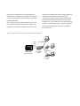
Catalyst
DATA SHEET
Catalyst Inline Power Patch Panel
D EPLOYED IN THE WIRING CLOSET, THE C ATALYST I NLINE P OWER P ATCH P ANEL PROVIDES F AST
E THERNET ENHANCEMENTS NEEDED FOR MULTISERVICE NETWORKING WHILE PRESERVING CUSTOMER
INVESTMENTS IN EXISTING
C ATALYST ® SWITCH EQUIPMENT.
The Catalyst Inline Power Patch Panel extends the features and functionality of
the award-winning Catalyst family of switches.
The inline power feature will work over a customer’s
existing Category 5 UTP installations. The Catalyst inline
power implementation passes the required domestic and
international safety regulations and compliance measures.
These modules are fully compliant with the 802.3 standard
when no inline power is supplied. The 802.3 standard does
not include specifications for providing power over the
Ethernet. This omission will be amended by the 802.3af task
force currently under way in the Institute of Electrical and
Electronic Engineers (IEEE). Cisco is committed to
standards-based operation and will support the IEEE in its
Inline Power
The Catalyst Inline Power Patch Panel enables inline power
efforts to add Ethernet power specifications to the 802.3
Ethernet standard.
for Cisco multiservice enabled Catalyst switches. This
product supports a new feature called inline power. Inline
Phone Discovery
power is 48-volt DC power provided over standard Category
The Cisco phone discovery feature eases the network
5 unshielded twisted-pair (UTP) cable up to 100 meters.
management burden by automating the inline power feature.
Instead of requiring wall power, terminal devices such as IP
With phone discovery, the Catalyst Inline Powered Patch
telephones can utilize power provided from the Catalyst
Panel automatically detects the presence of an IP phone
Inline Power Patch Panel. This capability gives the network
and supplies inline power. This means that network
administrator centralized power control, which translates
administrators can maintain centralized control without the
into greater network availability. By deploying Catalyst gear
need to manually enable each port to supply inline power.
with uninterruptable-power-supply (UPS) systems in secured
The phone discovery mechanism is intelligent enough to
wiring closets, network administrators can ensure that
differentiate between an IP phone and a network interface
building power outages will not affect network telephony
card (NIC), and will not supply inline power to a NIC or
connections.
other device not designed to use inline power. Network
interfaces are accessible from the front, ideal placement for
administrators can depend upon automatic and centralized
network administrators who manage wiring-closet
control of inline power that is safe to deploy and maintain.
connections. To support 48 users, the Inline Power Patch
Panel provides 96 RJ-45 ports, 48 ports to connect with
Flexible Form Factor
Catalyst switch ports, and 48 ports to connect with the end
Each Catalyst Inline Power Patch Panel supports up to 48
stations or terminal devices. Figure 1 shows an example of
users. Multiple Catalyst Inline Power Patch Panels can be
the Inline Power Patch Panel used without a traditional
deployed in a wiring closet to support more users. All the
Figure 1
RJ-45 patch panel.
Catalyst Inline Power Patch Panel used without a traditional RJ-45 path panel.
RJ-45
Patch
Cords
No DC Power
IP
Catalyst Switch
(without inline
power modules)
Catalyst
Power Patch
Panel
Injects
DC Power
IP
Cisco 7960
IP Phone
The Catalyst Inline Power Patch Panel can also work in
administrators can count on reliable power distribution that
conjunction with the existing patch-panel configuration
will not interfere with network operations that do not require
(see Figure 2). Ethernet terminals use pins 1, 2, 3, and 6
inline power.
for data transmission, and the Catalyst Inline Power Patch
Plug and Play
Panel does not access or insert power into these wire pairs.
Fast installation requires no special tools or training. No
The Catalyst Inline Power Patch Panel acts as a normal patch
configuration is necessary for the Catalyst Inline Power Patch
panel for Ethernet connections that do not require inline
Panel. The phone discovery mechanism is on by default, and
power, ensuring reliable performance by keeping unneeded
it automatically detects phones and supplies inline power.
circuitry out of these normal patch-panel connections. The
The rugged, self-contained design ensures reliable everyday
Catalyst Inline Power Patch Panel provides power only on
performance. Its compact size, only two rack units (RUs)
the unused Fast Ethernet pins 4, 5, 7, and 8. Network
high, allows easy rack mounting and preserves valuable
space in the wiring closet.
Figure 2
Catalyst Inline Power Patch Panel used with existing patch-panel configuration.
RJ-45
Patch
Panel
No DC Power
IP
Catalyst Switch
(without inline
power modules)
Catalyst
Power Patch
Panel
Injects
DC Power
IP
Cisco 7960
IP Phone
Ordering Information:
Modularity
8-pin, 4-pair
Product Number
Description
WS-PWR-PANEL
Catalyst Inline Power Patch Panel
Pin-Out
EIA T568A and T568B
Mechanical Performance
Specifications
Insertion Life
750 cycles minimum
Dimensions
(H x W x D) (3.4 x 17.2 x 12.0 in.) (8.6 x 43.7 x 30.5 cm)
Plug/Jack Contact Force
100 grams minimum using FCC-approved plug
Weight
12 lb (5.4 kg)
Plug Retention Force
30 lb (133 Newtons) minimum
Mounting
19-in. rack-compatible (rack and cable guide
Environmental Conditions
hardware included)
Operating Temperature
Power Requirements
32 to 104 F (0 to 40 C)
AC Input Voltage: 85 to 264 VAC
Storage Temperature
AC Frequency: 47 to 63 Hz
–40 to 185 F (–40 to 85 C)
AC Input Current: 4A at 100 VAC, 2A at 240 VAC
System Power Dissipation: 330W
KVA Rating: 0.35 KVA max
Inline Power Specifications
Pin Assignments: 4&5, 7&8
Relative Humidity
10% to 90%, noncondensing
Operating Altitude
–500 to 10,000 ft. (–152 to 2050 m)
Output Power Voltage: –48 VDC (nominal)
Regulatory Compliance
Heat Dissipation
Safety Certifications
1125 Btu/hr max
– UL 1950
– EN 60950
Modular Jacks
– CSA-C22.2 No. 950-95
Compliance
– IEC 60950
8-pin modular jacks conform to all requirements specified
– AS/NZS 3260
in FCC regulations (Part 68, Subpart F, “Connectors”)
and in ISO 8877, First Edition (“Information Processing
Systems—Interface connector and contact assignments for
ISDN basic access interface located at reference points
S and T”)
Electromagnetic Emissions Certifications
– FCC 15J Class A
– VCCI Class A with UTP, Class B with STP cables
– CE marking
– EN 55022 Class A with UTP, Class B with STP cables
CISPR 22 Class B
Service and Support
Cisco AVVID (Architecture for Voice, Video and Integrated
Data) support solutions are designed for one purpose—to
ensure customer success by delivering a suite of proactive
services. The award-winning Cisco internetworking service
and support offerings provide presales network audit
planning, design consulting, network implementation,
operational support, and network optimization. Cisco
interactive knowledge-transfer solutions enhance customer
success by leveraging Cisco expertise and experience. By
including service and support when purchasing Cisco AVVID
products, customers can confidently deploy AVVID networks
utilizing Cisco expertise, experience, and resources.
Corporate Headquarters
Cisco Systems, Inc.
170 West Tasman Drive
San Jose, CA 95134-1706
USA
http://www.cisco.com
Tel: 408 526-4000
800 553-NETS (6387)
Fax: 408 526-4100
European Headquarters
Cisco Systems Europe
11, Rue Camille Desmoulins
92782 Issy Les Moulineaux
Cedex 9
France
http://www-europe.cisco.com
Tel: 33 1 58 04 60 00
Fax: 33 1 58 04 61 00
Americas
Headquarters
Cisco Systems, Inc.
170 West Tasman Drive
San Jose, CA 95134-1706
USA
http://www.cisco.com
Tel: 408 526-7660
Fax: 408 527-0883
Asia Headquarters
Nihon Cisco Systems K.K.
Fuji Building, 9th Floor
3-2-3 Marunouchi
Chiyoda-ku, Tokyo 100
Japan
http://www.cisco.com
Tel: 81 3 5219 6250
Fax: 81 3 5219 6001
Cisco Systems has more than 200 offices in the following countries. Addresses, phone numbers, and fax numbers are listed on the
C i s c o C o n n e c t i o n O n l i n e We b s i t e a t h t t p : / / w w w. c i s c o . c o m / g o / o f fi c e s .
Argentina • Australia • Austria • Belgium • Brazil • Canada • Chile • China • Colombia • Costa Rica • Croatia • Czech Republic • Denmark • Dubai, UAE
Finland • France • Germany • Greece • Hong Kong • Hungary • India • Indonesia • Ireland • Israel • Italy • Japan • Korea • Luxembourg • Malaysia
Mexico • The Netherlands • New Zealand • Norway • Peru • Philippines • Poland • Portugal • Puerto Rico • Romania • Russia • Saudi Arabia • Singapore
Slovakia • Slovenia • South Africa • Spain • Sweden • Switzerland • Taiwan • Thailand • Turkey • Ukraine • United Kingdom • United States • Venezuela
Copyright © 2000, Cisco Systems, Inc. All rights reserved. Printed in the USA. Catalyst, Cisco, Cisco IOS, Cisco Systems, and the Cisco Systems logo are registered trademarks of Cisco Systems, Inc. or its affiliates
in the U.S. and certain other countries. All other trademarks mentioned in this document are the property of their respective owners. The use of the word partner does not imply a partnership relationship between
Cisco and any of its resellers. (9912R)
5/00 LW