1
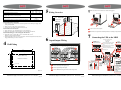
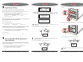
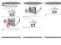
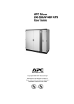
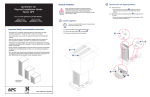
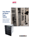
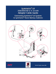
1
Maintenance Bypass Panel
(MBP) 60 kW
IMPORTANT SAFETY INSTRUCTIONS
SAVE THESE INSTRUCTIONS
for
Symmetra® PX 10 - 40kW, 400 V
2
1
This guide contains important instructions for the UPS and MBP that should be followed during the handling of UPS, batteries and MBP.
Total Power OFF Procedure
Mains Power in the
Off Position
WARNING!
Risk of Electric Shock.
CAUTION!
Read this important information.
3
Indicates that a switch or current protection
device is in the “ON” position.
?
Indicates that a switch is in the “OFF” position.
4
18 - 32 kg
32 - 54 kg
BATTERY
UNIT
UNIT
BATTERY
All power and
battery
modules must
be removed
< 18 kg
UNIT
BATTERY
4
Do not lift heavy loads
without assistance.
BATTERY
UNIT
2
e
•
All electrical power and power control wiring must be installed by a qualified electrician
and comply with local and national regulations.
Before working on the MBP, ensure that mains power is disconnected to the MBP and that
Q1, Q2 and Q3 are in the OFF position.
Sym
metr
10
Basi - 40 kW,a® PX
c Ope
200
ratio
V
Sym n Guid
metr
e
10
Basi - 40 kW,a® PX
c Ope
200
ratio
V
n Guid
•
System Enable
Switch in the
Off position.
DC Disconnect
Switch in the
Off position.
Figure 2.1
>54 kg
Figure 1.1
3
Install the Maintenance Bypass Panel in an Indoor, Controlled Environment
Temperature
Range:
0°-40°C
Keep Ventilated
Front-to-Rear
Airflow
Relative
Humidity: <95%
Non-condensing
Free of Conductive
Dust or
Corrosive Fumes
Max.
Elevation:
0-3,000 m
System Electrical Requirements
CAUTION!
All electrical power and power control wiring must be installed by a qualified
electrician, and must comply with local and national regulation for maximum power
rating.
Full Heat Loss at Nominal Mains: 9,496 BTU/hr (2,780 Watts)
Figure 1.2
UPS 40kW (40kVA) Output Rating
Input Voltage +/- 15% at nominal voltages
380V
Input Current (nominal, per phase)
Maximum Input Current (continuous, at minimum mains voltage)
Input Current Protection (external to enclosure, not supplied)
Input Frequency
Maintenance Bypass Panel 60kW / Symmetra® PX 10 - 40 kW, 400V
Maintenance Bypass Panel 60kW / Symmetra® PX 10 - 40 kW, 400V
990-1277
66A
3-Phase
400V 415V
62A
60A
88 A
100A *note 4
50 Hz
Maintenance Bypass 60kW / Symmetra® PX 10 - 40 kW, 400V
990-1277
990-1277
Output Voltage (on line)
380V
Output Current (nominal, per phase)
3-Phase
400V 415V
61A
58A
Maximum Output Current
(in bypass only at 125% overload, per phase)
56A
5
Make sure unit is in its location of use before wiring begins.
Wiring Overview
Rear Wiring
Bottom Wiring
76 A
Neutral Output Current (with 100% switch mode load)
Output Current Protection (external to enclosure, not supplied)
106A
100A
*note 7
MAINTENANCE
BYPASS PANEL
96A
EPO
POWER
1
INTERFACE WIRING
63A *note 5
SYMMETRA PX
Recommended Source Connections
Output
Power
1) Input electricity to be provided from a dedicated, grounded 4-wire WYE power supply source
with a grounded neutral.
2) Ensure clockwise voltage phase rotation (L1,L2,L3).
3) All wire sizes must comply with national and local codes.
2
2
Input
Power
1
1
Recommended Current Protection
1
Loosen screws to remove plate.
4) Input; 100 Amp gL type current-limiting fuse on each input phase.
5) Output; 63 Amp 3-Pole AC circuit breaker or a 63 Amp gL fuse with 30kAIC.
2
Punch holes as required and reinstall panel before mounting wiring hardware.
Recommended Wiring for a 40°C Temperature Environment
6) Input cables: 35mm2. Output cables: 16 mm2. External PE cable: 16 mm2.
Refer also to local electrical regulations.
7) Neutral Output Wires; rate for 173% of output phase current if feeding all Switch Mode Power
Supply loads without power factor correction.
4
Wall Fitting
6
7
Connecting the UPS to the MBP
Power Terminal Lug Diameter is 8 mm,
Torque Value: 6Nm.
Input/Output Wiring
CAUTION!
Ensure clockwise phase
rotation and neutral location
X001
N
L1
L2
L3
1
2 Make Ground connections as shown. Feed ground
wire through Ferrite beads provided.
SYSTEM OUTPUT
L1
L2 L3
N
2
2
B
1
X004
SYSTEM INPUT
L3
L1 L2
N
CAUTION!
Ensure clockwise phase
rotation and neutral location
Wiring Steps
1 Connect power input and output wiring to terminals
as shown. Route Input and Output in separate
conduits.
3 Connect EPO as shown schematically in Section 5.
4 Connect MBP as shown.
4
J3
3
Weight of MBP: 30 kg.
A
J1
J6
1
Fixing holes. in rear box
UPS INPUT
3
Input/Output Wiring of Maintenance Bypass
Panel (MBP)
Output Relays:
1
240V/8A
UPS OUTPUT
Emergency shut-down
with internal supply
N/O EPO Control N/C EPO Control
4 x ø 8.5 mm
Figure 4.1
Maintenance Bypass Panel 60kW / Symmetra® PX 10 - 40 kW, 400V
1
2
3
Connect UPS Input and Output power.
4
3/2
Connect System Input and Output.
1
Connect Maintenance Bypass Panel control wiring, X010.
Maintenance Bypass Panel 60kW / Symmetra® PX 10 - 40 kW, 400V
990-1277
Ground
8
Relay Coil 1
7/6
Internal Power 5
+24V Supply
Ground
Relay Coil 2
Internal Power
+24V Supply
Emergency Power
OFF Switch Keep
AC
DC Input
EPO wire routing
Output (Optional XR)
isolated and
use separate
EPO conduit
2
AC
Input
0.3VA/1.9kW
Input signals: Contact load: TTL
Q001 UPS input switch (N/O position)
3/4 Q002 UPS output switch (N/O position)
5/6 Q003 UPS service bypass switch
(N/C position)
7/8 OK to operate UPS Output switch Q002
9/10 OK to operate service bypass switch
Q003
11/12 Not used
13/14 External Switch Gear present
1/2
Maintenance Bypass Panel60kW / Symmetra® PX 10 - 40 kW, 400V
990-1277
990-1277
8
4) Set the Symmetra PX UPS System Enable switch and DC Disconnect breaker to the STANDBY
position.
Input/Output Wiring
Control
Status
Setup
Accessories
This procedure will ensure correct wiring of Maintenance Bypass Panel
1 Ensure that both the DC Breaker and System Enable Switch are in the “OFF” or “STAND-BY” position.
2 Torque terminal screws to 1.6-1.8Nm, and terminal bolts to 6Nm. Verify wires in
terminal block X010. Wires 1-10 to be connected to equipment interface 1-10.
3 Apply power to system input of Maintenance Bypass Panel and measure voltage at input terminal
block (X001). Measure and record voltages below between
L1 and Neutral: __________ L2 and Neutral: __________
c) Select UPS into Bypass on the Control menu and press the ENTER key.
d) Confirm the selection on the next screen: Select Yes, UPS into Bypass and press the ENTER
key. The BYPASS LED will illuminate and the display will show the following to screens:
UPS has been
commanded to go
into Bypass...
L3 and Neutral: __________
4 Ensure that phase rotation is correct.
Measured voltage must be 230 +/- 10%. If not, STOP! Verify correct wiring from the
power source to the input wiring connections. Repeat step 1.
5 Ensure that wiring is correct.
6 Switch on Q001, Q003 and Q002
7 Measure voltage between input and output points on the Symmetra PX.
UPS load is in Bypass
Press any key...
5) If applicable, set the XR Battery Enclosure DC Disconnect breaker to the STANDBY position.
L1 input & L1 output: ________ L2 input & L2 output ________ L3 input & L3 output ________
Measured voltage must be 0 Volt + /-2 Volt. If not, STOP! Verify correct wiring from
Maintenance Bypass Panel to Symmetra PX to Maintenance Bypass Panel.
Logging
Display
Diags
Help
The H3 LED above the Q3 breaker should illuminate, indicating that it is safe to operate the Q3 breaker.
2) Close (turn ON) the Q3 breaker on the Maintenance Bypass Panel.
8 Successful completion of steps 1 through 7 indicates that the Maintenance Bypass Panel wiring is
correctly installed and functioning correctly. Turn off breakers and switches and shut down input power
to the system. Reinstall all wiring access panels on the Symmetra PX.
Service Bypass
Switch
Wiring completed by:
Name: _________________________________________________ Date: _____________
9
UPS
6) Open (turn OFF) the Q1 breaker on the Service Bypass Panel.
How to place the UPS into maintenance
bypass operation
The H2 LED above the Q2 breaker should illuminate indicating that it is safe
to operate the Q2 breaker.
3) Open (turn OFF) the Q2 breaker on the Service Bypass Panel.
Service Bypass
Switch
When servicing the UPS, place the UPS into maintenance bypass operation. When the UPS is
operating in maintenance bypass, power flows directly from the utility to the Service Bypass
Panel and out to the load equipment.
UPS
Service Bypass
Switch
1) Command the UPS into static bypass operation through the UPS display interface:
a) Press the ESC key at the Monitoring screen to open the Main menu.
b) Select Control on the Main menu and press the ENTER key.
UPS
Maintenance Bypass Panel 60kW / Symmetra® PX 10 - 40 kW, 400V
When steps 1-6 have been completed, the UPS will be in maintenance bypass
operation.
Maintenance Bypass Panel 60kW / Symmetra® PX 10 - 40 kW, 400V
990-1277
Maintenance Bypass 60kW / Symmetra® PX 10 - 40 kW, 400V
990-1277
990-1277
10
How to return to On-Line from
Maintenance Bypass Operation
5) Open (turn OFF) the Q3 breaker on the Maintenance Bypass Panel.
3) If applicable, set the XR Battery Enclosure DC Disconnect breaker to ON.
1) Close (turn ON) the Q1 breaker on the Maintenance Bypass Panel.
Service Bypass
Switch
UPS
Service Bypass
Switch
UPS
As soon as you open the Q3 breaker, the UPS will automatically return from Static
Bypass.
The H2 LED above the Q2 breaker will illuminate, indicating that it is safe to
operate the Q2 breaker.
2) Set the Symmetra PX UPS DC Disconnect breaker and System Enable switch to the ON
position.
4) Close (turn ON) the Q2 breaker on the Service Bypass Panel.
Service Bypass
Switch
UPS
The H3 LED above the Q3 breaker will illuminate, indicating that it is safe to
operate the Q3 breaker.
As soon as you set the DC Disconnect breaker and the System Enable switch to the
ON position, the UPS transfers to Static Bypass (with the load supported).
Maintenance Bypass Panel 60kW / Symmetra® PX 10 - 40 kW, 400V
.
Maintenance Bypass Panel 60kW / Symmetra® PX 10 - 40 kW, 400V
990-1277
Maintenance Bypass Panel60kW / Symmetra® PX 10 - 40 kW, 400V
990-1277
990-1277