1
Smart-UPS® VT
10-40kVA
400V
Site Preparation and
Installation Manual
This manual is available in English on the enclosed CD.
Uživatelská pøíruèka v èeštinì je k dispozici na pøiloženém CD.
Dieses Handbuch ist in Deutsch auf der beiliegenden CD-ROM verfügbar.
Deze handleiding staat in het Nederlands op de bijgevoegde cd.
Este manual está disponible en español en el CD-ROM adjunto.
Ce manuel est disponible en français sur le CD-ROM ci-inclus.
A hasznalati utasitas magyarul megtalalhato a csatolt CD-n.
Questo manuale è disponibile in italiano nel CD-ROM allegato.
Denne manualen er tilgjengelig på norsk på vedlagte CD.
Instrukcja Obslugi w jêzyku polskim jest dostêpna na CD.
O manual em Português está disponível no CD-ROM em anexo.
Ilpqoriuh~ nm hpnmj{gmb`lh} l` orppimk ~gzie nohj`c`eqp~ l` dhpie (CD).
Denna manual finns tillgänglig på svenska på medföljande CD.
Bu kullanim kilavuzunun Türkçe'sä, äläxäkte gönderälen CD äçeräsände mevcuttur.
您可以从包含的 CD 上获得本手册的中文版本。
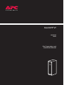
Smart-UPS® VT 10-40kVA 400V
Site Preparation and Installation Manual
IMPORTANT!
THIS DOCUMENT CONTAINS IMPORTANT SAFETY INSTRUCTIONS PLEASE SAVE THESE INSTRUCTIONS!
Smart-UPS® VT 10-40kVA, 400V, Site Preparation and Installation Manual – 990-1986
1
Smart-UPS® VT 10-40kVA, 400V, Site Preparation and Installation Manual – 990-1986
Contents
Introduction ............................................................1
General Safety Instructions . . . . . . . . . . . . . . . . . . . . . . . . . . . . 2
Warning/note symbols . . . . . . . . . . . . . . . . . . . . . . . . . . . . . . . 2
Environmental symbols . . . . . . . . . . . . . . . . . . . . . . . . . . . . . . . 2
General safety . . . . . . . . . . . . . . . . . . . . . . . . . . . . . . . . . . . . . . 3
UPS Family Range and Components . . . . . . . . . . . . . . . . . . . . . 5
14in/351mm Enclosures . . . . . . . . . . . . . . . . . . . . . . . . . . . . . . 5
20in/523mm Enclosures . . . . . . . . . . . . . . . . . . . . . . . . . . . . . . 5
UPS sizes, weights and runtime configurations . . . . . . . . . . . . . 6
Battery Module . . . . . . . . . . . . . . . . . . . . . . . . . . . . . . . . . . . . . 6
Front Panels . . . . . . . . . . . . . . . . . . . . . . . . . . . . . . . . . . . . . . . 7
Stabilizing Bracket . . . . . . . . . . . . . . . . . . . . . . . . . . . . . . . . . . . 8
User interface . . . . . . . . . . . . . . . . . . . . . . . . . . . . . . . . . . . . . . 9
Options . . . . . . . . . . . . . . . . . . . . . . . . . . . . . . . . . . . . . . . . . 10
Extended Run Battery Enclosure (XR Enclosure) and
Battery Module . . . . . . . . . . . . . . . . . . . . . . . . . . . . . . . . . . . . 10
Part Numbers for XR Enclosures . . . . . . . . . . . . . . . . . . . . . . . 11
Part Number for Battery Module . . . . . . . . . . . . . . . . . . . . . . . 11
Maintenance Bypass Panels with Power Distribution Capability 12
Seismic anchoring / battery securing equipment . . . . . . . . . . . 12
Site Preparation (UPS and XR) ................................14
Installation Space Requirements . . . . . . . . . . . . . . . . . . . . . . . 14
Clearance for 20in/523mm Enclosures . . . . . . . . . . . . . . . . . . 14
Clearance for 20 in/523 mm Enclosures in installations
including an XR Enclosure . . . . . . . . . . . . . . . . . . . . . . . . . . . . 15
Clearance for stand-alone 14in/351mm Enclosures . . . . . . . . . 16
Clearance for 14in/351 mm Enclosures in installations
including XR Enclosures . . . . . . . . . . . . . . . . . . . . . . . . . . . . . 17
Seismic Anchoring Preparation . . . . . . . . . . . . . . . . . . . . . . . . 18
Drilling floor holes for seismic anchoring . . . . . . . . . . . . . . . . . 18
Hole positions for seismic bolts . . . . . . . . . . . . . . . . . . . . . . . . 18
Smart-UPS® VT 10-40kVA, 400V, Site Preparation and Installation Manual – 990-1986
i
Operating Environment . . . . . . . . . . . . . . . . . . . . . . . . . . . . . 20
Operating conditions . . . . . . . . . . . . . . . . . . . . . . . . . . . . . . . . 20
Heat dissipation . . . . . . . . . . . . . . . . . . . . . . . . . . . . . . . . . . . 20
Audible noise . . . . . . . . . . . . . . . . . . . . . . . . . . . . . . . . . . . . . 20
Recommended source connections . . . . . . . . . . . . . . . . . . . . . 21
Recommended current protection . . . . . . . . . . . . . . . . . . . . . . 22
Minimum setting of breakers for 10kVA UPS . . . . . . . . . . . . . . 23
Minimum setting of breakers for 15kVA UPS . . . . . . . . . . . . . . 23
Minimum setting of breakers for 20kVA UPS . . . . . . . . . . . . . . 24
Minimum setting of breakers for 30kVA UPS . . . . . . . . . . . . . . 24
Minimum setting of breakers for 40kVA UPS . . . . . . . . . . . . . . 25
Recommended phase-conductor sizes [AWG] for a 104°F
(40°C) temperature environment . . . . . . . . . . . . . . . . . . . . . . . 26
EPO switch wiring . . . . . . . . . . . . . . . . . . . . . . . . . . . . . . . . . . 26
Basic Wiring Overview . . . . . . . . . . . . . . . . . . . . . . . . . . . . . . 27
Site Preparation Checklist . . . . . . . . . . . . . . . . . . . . . . . . . . . . 28
Electrical Installation ............................................ 29
Total-Power-Off Procedure . . . . . . . . . . . . . . . . . . . . . . . . . . . 29
System-Electrical Information . . . . . . . . . . . . . . . . . . . . . . . . . 31
Source connections . . . . . . . . . . . . . . . . . . . . . . . . . . . . . . . . . 32
Wiring . . . . . . . . . . . . . . . . . . . . . . . . . . . . . . . . . . . . . . . . . . 33
Input/Output Wiring – Single Mains (default) . . . . . . . . . . . . . 34
Wiring procedure - single mains . . . . . . . . . . . . . . . . . . . . . . . 34
Input/Output Wiring – Dual Mains . . . . . . . . . . . . . . . . . . . . . 36
Wiring procedure - dual mains . . . . . . . . . . . . . . . . . . . . . . . . . 36
Communication Wiring to EPO and Optional Equipment . . . . 38
J106 and J108 pin connections . . . . . . . . . . . . . . . . . . . . . . . . 38
J106 UPS pin connections to J200 options . . . . . . . . . . . . . . . . 39
XR Enclosure, MBP, and Generator Control wiring . . . . . . . . . . 39
EPO wiring options (J108) . . . . . . . . . . . . . . . . . . . . . . . . . . . . 40
General Charge Setting . . . . . . . . . . . . . . . . . . . . . . . . . . . . . . 41
Charge setting procedure . . . . . . . . . . . . . . . . . . . . . . . . . . . . 41
Leveling Feet . . . . . . . . . . . . . . . . . . . . . . . . . . . . . . . . . . . . . 42
Setting the leveling feet . . . . . . . . . . . . . . . . . . . . . . . . . . . . . . 42
ii
Smart-UPS® VT 10-40kVA, 400V, Site Preparation and Installation Manual – 990-1986
Seismic Anchoring (option) . . . . . . . . . . . . . . . . . . . . . . . . . . . 43
Floor attachment . . . . . . . . . . . . . . . . . . . . . . . . . . . . . . . . . . 43
Battery securing . . . . . . . . . . . . . . . . . . . . . . . . . . . . . . . . . . . 44
Front Panel . . . . . . . . . . . . . . . . . . . . . . . . . . . . . . . . . . . . . . 45
Front Panel installation/removal . . . . . . . . . . . . . . . . . . . . . . . 45
Wiring Verification Procedure . . . . . . . . . . . . . . . . . . . . . . . . . 46
Installation Site Checklist . . . . . . . . . . . . . . . . . . . . . . . . . . . . 48
LIMITED FACTORY WARRANTY . . . . . . . . . . . . . . . . . . . . . . . . 49
APC product covered . . . . . . . . . . . . . . . . . . . . . . . . . . . . . . . . 49
Terms of warranty . . . . . . . . . . . . . . . . . . . . . . . . . . . . . . . . . . 49
Non-transferable Warranty extends to first purchaser for use . 49
Assignment of warranties . . . . . . . . . . . . . . . . . . . . . . . . . . . . 49
Drawings, descriptions . . . . . . . . . . . . . . . . . . . . . . . . . . . . . . 50
Warranty claims procedure . . . . . . . . . . . . . . . . . . . . . . . . . . . 50
Exclusions . . . . . . . . . . . . . . . . . . . . . . . . . . . . . . . . . . . . . . . . 50
Smart-UPS® VT 10-40kVA, 400V, Site Preparation and Installation Manual – 990-1986
iii
iv
Smart-UPS® VT 10-40kVA, 400V, Site Preparation and Installation Manual – 990-1986
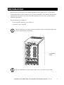
Introduction
Welcome to the Site Preparation and Installation Manual for the Smart-UPS® VT. This manual
contains information on how to prepare your site for the installation of the UPS and optional APC
equipment (also available at www.apc.com) and instructions on how to carry out the electrical/
mechanical installation.
Separate manuals are available on:
• Receiving and Unpacking - part # 990-1747
• Operation - part # 990-1985
The user manuals are provided in the documentation storage area at the top right corner
on the UPS (behind the Front Panel).
Note
Documentation
storage
For more information on APC products and services, visit us at www.apc.com
Note
Smart-UPS® VT 10-40kVA, 400V, Site Preparation and Installation Manual
– 990-1986
1
General Safety Instructions
This guide contains important instructions that should be followed when handling the UPS, Battery
Enclosures, and Batteries.
Warning/note symbols
WARNING!
Risk of electric shock.
CAUTION!
Read this information to avoid equipment damage.
Indicates important information.
Note
Indicates that more information is available on this subject in a different section of this
manual.
Indicates that more information is available on the same subject in a different manual.
Environmental symbols
Temperature
2
Ventilation
requirements
Humidity
Dust/Fumes
Smart-UPS® VT 10-40kVA, 400V, Site Preparation and Installation Manual
Altitude
– 990-1986
Introduction – General Safety Instructions
General safety
WARNING!
All electrical power and control wiring must be installed by a qualified electrician and
comply with local and national codes
WARNING!
When connected, the UPS contains energy from both AC and DC sources. If the UPS
has dual mains supply, be aware of the two AC supply sources. Hazardous voltage from
batteries may be present even when the unit is disconnected from the utility power
source(s). Follow the Total-Power-Off procedure in this manual to completely deenergize the system. Disconnect charging source prior to connecting or disconnecting
battery terminals.
WARNING!
Servicing of batteries should be performed or supervised by personnel knowledgeable
of batteries and the required precautions. Keep unauthorized personnel away from
batteries.
WARNING!
Batteries do not contain serviceable parts. Only APC authorized personnel may open
batteries.
WARNING!
Do not dispose of battery or batteries in a fire. The battery may explode. Do not open or
mutilate the battery or batteries. Released electrolyte is harmful to the skin and eyes. It
may be toxic.
WARNING!
Risk of Energy Hazard, 96 V, 7.2 Ampere-hour battery. Before replacing batteries,
remove watches, rings, or other metal objects. High energy through conductive
materials could cause severe burns.
WARNING!
When handling batteries, wear rubber gloves and boots. Do not lay tools or metal
objects on top of batteries.
Smart-UPS® VT 10-40kVA, 400V, Site Preparation and Installation Manual
– 990-1986
3
Introduction – General Safety Instructions
WARNING!
When replacing a battery module, replace with the same number of the: APC SYBT1
(always replace a whole Battery Module at a time).
WARNING!
Only trained personnel familiar with the construction and operation of the equipment
and the electrical and mechanical hazards involved, may install and remove system
components.
CAUTION!
Wait until you are ready to power up the system before installing Battery Modules in the
UPS. Failure to do so can result in a deep discharge of the batteries and cause permanent
damage (for 10-20kVA systems, the time from the battery installation time till the UPS
is powered up should not exceed 75 hours or 3 days. For 20-40 kVA systems, the time
should not exceed 96 hours, or 4 days).
For configurations including customer-supplied external batteries, refer to
manufacturer’s battery installation and maintenance instructions.
4
Smart-UPS® VT 10-40kVA, 400V, Site Preparation and Installation Manual
– 990-1986
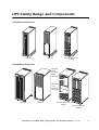
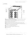
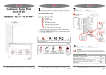
UPS Family Range and Components
14in/351mm Enclosures
Front view
Rear view
Front view without cover
10-20kVA
20in/523mm Enclosures
Blind plate
covers
any empty
Power
Module bay
Blind plates
cover
any empty
battery bays
Front view
Rear view
Front view without cover
10-20kVA
Front view without cover
30-40kVA
Smart-UPS® VT 10-40kVA, 400V, Site Preparation and Installation Manual
– 990-1986
5
Introduction – UPS Family Range and Components
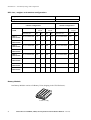
UPS sizes, weights and runtime configurations
Height (identical for all Enclosure sizes)
59in/1500mm
Depth (identical for all Enclosure sizes)
33.7in/856mm
Minimum
runtime configuration
Maximum
runtime configuration
Shipping
weight
Enclosure
width
Installed
weight
Installed
weight
APC Part No.
lbs
kg
lbs
kg
APC Part No.
lbs
kg
10kVA
14in/351mm
SUVT10KH1B2S
739
336
671
305
SUVT10KH2B2S
950
432
10kVA
20in/523mm
SUVT10KH1B4S
811
369
743
338
SUVT10KH4B4S
1444
657
15kVA
14in/351mm
SUVT15KH2B2S
950
432
882
401
SUVT15KH2B4S
954
434
15kVA
20in/523mm
SUVT15KH2B4S
1022
465
954
434
SUVT15KH4B4S
1444
657
20kVA
14in/351mm
SUVT20KH2B2S
456
432
882
401
SUVT20KH2B2S
954
434
20kVA
20in/523mm
SUVT20KH2B4S
1022
465
954
434
SUVT20KH4B4S
1376
626
30kVA
20in/523mm
SUVT30KH3B4S
1233
561
1165
530
SUVT30KH4B4S
1376
626
40kVA
20in/523mm
SUVT40KH4B4S
1433
653
1365
622
SUVT40KH4B4S
1376
626
Battery Module
One Battery Module consists of 4 Battery Units (shipping in the UPS Enclosure).
4 x 50lb / 4 x 23kg
6
Smart-UPS® VT 10-40kVA, 400V, Site Preparation and Installation Manual
– 990-1986
Introduction – UPS Family Range and Components
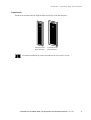
Front Panels
Install the Front Panel after the UPS has been electrically wired and started up.
Front Panel for 14in/
351mm Enclosure
Front Panel for 20in/
523mm Enclosure
Front Panel installation procedure described in the Front Panel section.
Smart-UPS® VT 10-40kVA, 400V, Site Preparation and Installation Manual
– 990-1986
7
Introduction – UPS Family Range and Components
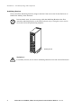
Stabilizing Bracket
Always install the Stabilizing Brackets (shipped with the UPS) on the 14in/351mm Enclosure to
enhance the stability of the Enclosure.
Note
In non-seismic areas, it is not necessary to bolt the Stabilizing Bracket to the floor.
Attach the Stabilizing Bracket to the UPS Enclosure only, re-using the screws used to
secure the UPS to the pallet during shipment.
Stabilizing Bracket
WARNING!
For stability reasons, do not remove Stabilizing Brackets from 14in/351mm Enclosures.
8
Smart-UPS® VT 10-40kVA, 400V, Site Preparation and Installation Manual
– 990-1986
Introduction – UPS Family Range and Components
User interface
Display: user-control interface used to configure the functionality, monitor the system, set alarm
thresholds, and to provide audible and visual alarms.
Network Management Card with Environmental Monitor (AP9619): used for remote system
control and monitoring, e-mail notifications etc.
Computer-interface port for the connection of computers with APC Powerchute® software.
Mechanical bypass lever: used to bypass the upstream utility power around the UPS to support
the load directly = internal mechanical bypass operation.
Service port (for APC maintenance personnel only).
Display port for the connection of display communication cable.
Documentation storage.
Smart-UPS® VT 10-40kVA, 400V, Site Preparation and Installation Manual
– 990-1986
9
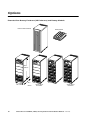
Options
Extended Run Battery Enclosure (XR Enclosure) and Battery Module
Enclosure with Front Panel
Battery Module
Serial:
Model:
BATTER
Y UNIT
Serial:
Model:
BATTER
Y UNIT
Serial:
Model:
BATTER
Y UNIT
BATTER
Y UNIT
59in /
1500mm
Serial:
Model:
BATTER
Y UNIT
Serial:
Model:
Serial:
Model:
BATTER
Y UNIT
Serial:
Model:
BATTER
Y UNIT
Serial:
Model:
BATTER
Y UNIT
BATTER
Y UNIT
BATTER
Y UNIT
BATTER
Y UNIT
BATTER
Y UNIT
Serial:
Model:
BATTER
Y UNIT
Serial:
Model:
Serial:
Model:
BATTER
Y UNIT
Serial:
Model:
BATTER
Y UNIT
Serial:
Model:
BATTER
Y UNIT
Serial:
Model:
BATTER
Y UNIT
Serial:
Model:
BATTER
Y UNIT
Serial:
Model:
BATTER
Y UNIT
Serial:
Model:
BATTER
Y UNIT
Serial:
Model:
BATTER
Y UNIT
Serial:
Model:
BATTER
Y UNIT
Serial:
Model:
BATTER
Y UNIT
Serial:
Model:
BATTER
Y UNIT
Serial:
Model:
Serial:
Model:
Serial:
Model:
Serial:
Model:
BATTER
Y UNIT
Serial:
Model:
BATTER
Y UNIT
Serial:
Model:
BATTER
Y UNIT
BATTER
Y UNIT
Serial:
Model:
BATTER
Y UNIT
Serial:
Model:
Serial:
Model:
BATTER
Y UNIT
Serial:
Model:
BATTER
Y UNIT
Serial:
Model:
BATTER
Y UNIT
Serial:
Model:
BATTER
Y UNIT
Serial:
Model:
BATTER
Y UNIT
Serial:
Model:
BATTER
Y UNIT
Serial:
Model:
Serial:
Model:
BATTER
Y UNIT
Serial:
Model:
BATTER
Y UNIT
BATTER
Y UNIT
Serial:
Model:
BATTER
Y UNIT
Serial:
Model:
BATTER
Y UNIT
Serial:
Model:
BATTER
Y UNIT
BATTER
Y UNIT
Serial:
Model:
BATTER
Y UNIT
Serial:
Model:
BATTER
Y UNIT
Serial:
Model:
Serial:
Model:
Serial:
Model:
BATTER
Y UNIT
Serial:
Model:
BATTER
Y UNIT
BATTER
Y UNIT
Serial:
Model:
BATTER
Y UNIT
Serial:
Model:
BATTER
Y UNIT
Serial:
Model:
BATTER
Y UNIT
Serial:
Model:
BATTER
Y UNIT
Serial:
Model:
Serial:
Model:
BATTER
Y UNIT
Serial:
Model:
BATTER
Y UNIT
BATTER
Y UNIT
Serial:
Model:
BATTER
Y UNIT
Serial:
Model:
Serial:
Model:
BATTER
Y UNIT
Serial:
Model:
BATTER
Y UNIT
BATTER
Y UNIT
BATTER
Y UNIT
Serial:
Model:
BATTER
Y UNIT
Serial:
Model:
BATTER
Y UNIT
Serial:
Model:
Serial:
Model:
Serial:
Model:
BATTER
Y UNIT
BATTER
Y UNIT
Serial:
Model:
BATTER
Y UNIT
32in /
20in / 523mm
10
810mm
Version without
DC breaker
Smart-UPS® VT 10-40kVA, 400V, Site Preparation and Installation Manual
Version without
DC breaker
– 990-1986
Introduction – Options
XR Enclosure weights Minimum runtime:
2 Battery Modules
887lbs/403kg
6 Battery Modules
1731lbs/787kg
Battery Module weight
4 units = 1 Battery Module
4x50lb / 4x23kg
Part Numbers for XR Enclosures
XR Enclosure
Enclosure with 2 Battery Modules (expandable to 6), and DC breaker:
SUVTBXR2B6S
Enclosure with 2 Batterry Modules (expandable to 6), without DC breaker:
SUVTXR2B6S
Enclosure with 6 Battery Modules, and DC breaker:
SUVTBXR6B6S
Enclosure with 6 Battery Modules, without DC breaker
SUVTXR6B6S
Part Number for Battery Module
Battery Module
Battery Module
SYBT4
Smart-UPS® VT 10-40kVA, 400V, Site Preparation and Installation Manual
– 990-1986
11
Introduction – Options
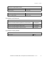
Maintenance Bypass Panels with Power Distribution Capability
Further details on APC Maintenance Bypass Panel (MBP) with Power Distribution
Capability are available on www.apc.com.
Note
MBP
(wall-mount)
MBP (line-up-and-match) with Power
Distribution Capability
37.36in/
949mm
29.53in/
750mm
MBP (line-up-and-match)
59in/
1500mm
7.48in/
190mm
14in/350mm
36.4in/
925mm
The Maintenance Bypass Panel provides overcurrent protection to the entire UPS system. It is also
used to bypass the utility power around the UPS instead of through the system, e.g. when UPS
maintenance is carried out.
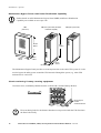
Seismic anchoring / battery securing equipment
In seismic areas, each Battery Module must be secured with a Seismic Battery Bracket.
Seismic Battery Bracket
Reuse transport
brackets
as Seismic Brackets
Floor-anchoring bolts for the Seismic Bracket are not provided with the UPS. Purchase
the floor bolts locally.
Note
12
Smart-UPS® VT 10-40kVA, 400V, Site Preparation and Installation Manual
– 990-1986
Introduction – Options
Note
For more details on optional APC equipment for the APC Smart-UPS® VT, contact APC
Technical Support in the U.S. at 800-555-2725. For other countries, see technical
support numbers on rear cover.
Smart-UPS® VT 10-40kVA, 400V, Site Preparation and Installation Manual
– 990-1986
13
Site Preparation (UPS and XR)
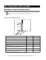
Installation Space Requirements
Allow for enough working space behind the Enclosure for electrical work to be carried
out (e.g. if you want to connect an XR Enclosure at a later stage).
Note
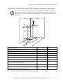
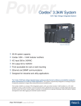
Clearance for 20in/523mm Enclosures
(A)
(B)
UPS
(C)
(D)
(G)
(E)
Space requirements
in
mm
Minimum clearance above Enclosure (A)
20
523
Enclosure depth (B)
36.4
925
Enclosure width (C)
20
523
Minimum free rear space for ventilation* (D)
4
100
Minimum front clearance (E)
39.3
1000
Conduit Box, depth (F)
3.5
88
No side clearance required (add width of Enclosure Stabilizing
Brackets for seismic protection if applicable)*
0
0
Stabilizing Bracket width
3.3
85
Total installation depth, inclusive of Front Panel, Conduit Box
and minimum front and rear clearances (G)
111
2025
*) All physical installations must comply with local standards.
14
Smart-UPS® VT 10-40kVA, 400V, Site Preparation and Installation Manual
– 990-1986
Site Preparation (UPS and XR) – Installation Space Requirements
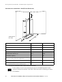
Clearance for 20 in/523 mm Enclosures in installations including an XR Enclosure
Note
As seismic anchoring is carried out prior to wiring (and to busbar connection between
UPS and XR Enclosures if applicable), allow for sufficient working space behind the unit
for electrical work to be carried out (including busbar connections between Enclosures if
applicable).
(A)
(B)
XR
UPS
(D)
(C)
(C)
(G)
(E)
Space requirements
in
mm
Minimum clearance above Enclosures (A)
20
523
Enclosure depth (B)
36.4
925
Enclosure width (C)
20 (x 2)
523 mm (x 2)
Minimum free rear space for ventilation* (D)
4
100
Minimum front clearance (E)
39.3
1000
Conduit Box, depth (F)
3.5
88
No side clearance required (include width of Stabilizing Bracket
for seismic protection if applicable)*
0
0
Stabilizing Bracket width
3.3
85
Total installation depth, inclusive of Front Panel, Conduit Box
and minimum front and rear clearances (G)
79.7
2025
*) All physical installations must comply with local standards.
Smart-UPS® VT 10-40kVA, 400V, Site Preparation and Installation Manual
– 990-1986
15
Site Preparation (UPS and XR) – Installation Space Requirements
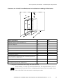
Clearance for stand-alone 14in/351mm Enclosures
(A)
(B)
UPS
(C)
(D)
Stabilizing Bracket,
left and right
(G)
(E)
Space requirements
in
mm
Minimum clearance above UPS (A)
20
523
UPS depth (B)
36.4
925
UPS width
14
351
Minimum free rear space for ventilation* (D)
4
100
Minimum front clearance (E)
39.3
1000
Conduit Box, depth (F)
3.5
88
No side clearance required (add width of Stabilizing
Bracket for seismic protection if applicable)*
0
0
Stabilizing Bracket width
3.3
85
Total installation depth, inclusive of Front Panel, Conduit
Box and minimum front and rear clearances (G)
111
2025
*) All physical installations must comply with local standards.
For the stability of 14/351 mm stand-alone Enclosures, the Stabilizing Bracket must
always be mounted on both sides of the UPS. Follow the Seismic Anchoring procedures
for attachment.
16
Smart-UPS® VT 10-40kVA, 400V, Site Preparation and Installation Manual
– 990-1986
Site Preparation (UPS and XR) – Installation Space Requirements
Clearance for 14in/351 mm Enclosures in installations including XR Enclosures
(A)
(B)
UPS
XR
(C2)
(C1)
(D)
(G)
(E)
Space requirements
in
mm
Minimum clearance above Enclosures (A)
20
523
Enclosure depth (B)
36.4
925
Enclosure width (C1)
14
351
Enclosure width (C2)
20
523
Minimum free rear space for ventilation* (D)
4
100
Minimum front clearance (E)
39.3
1000
Conduit Box, depth (F)
3.5
88
No side clearance required (add width of Stabilizing Bracket for
seismic protection if applicable)*
0
0
Stabilizing Bracket width
3.3
85
Total installation depth, inclusive of Front Panel, Conduit Box
and minimum front and rear clearances (G)
111
2025
*) All physical installations must comply with local standards.
For the stability of 14/351 mm stand-alone Enclosures, the transport brackets (re-use of
brackets used to secure the UPS to the shipping pallet) must always be mounted on both
sides of the UPS. Follow the Seismic Anchoring procedures.
Smart-UPS® VT 10-40kVA, 400V, Site Preparation and Installation Manual
– 990-1986
17
Seismic Anchoring Preparation
Note
If seismic protection is required in your area, read this section. If not, proceed to
Operating Environment. However, if you install a 14in/351mm Enclosure, it must
always be equipped with the Enclosure Stabilizing Bracket for enhanced stability (not
necessary to bolt the Enclosure Stabilizing Bracket to the floor in non-seismic areas).
Drilling floor holes for seismic anchoring
Note
If your UPS installation requires seismic protection, the UPS installation must be
anchored to the floor, re-using the brackets that also secured the Enclosure to the pallets
when shipped. For easy determination of where to drill the holes, refer to the applicable
drawings below indicating hole positions and size.
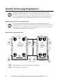
Hole positions for seismic bolts
Rear
Seismic
bolt hole
Seismic
bolt hole
Top view of bottom
plate of 20in/523
mm Enclosure
20in/523mm
Rear
Seismic
bolt hole
Seismic
bolt hole
25in/650mm
Seismic
bolt hole
Seismic
bolt hole
Top view of
bottom plate of
14in/351 mm
Enclosure
14in/351mm
Refer to this drawing for seismic bolt positions for 20in/523mm.
Refer to this drawing for 14in/351mm.
18
Smart-UPS® VT 10-40kVA, 400V, Site Preparation and Installation Manual
– 990-1986
Seismic
bolt hole
Castor
Seismic
bolt hole
Site Preparation (UPS and XR) – Seismic Anchoring Preparation
Recommended minimum number of floor bolts per Enclosure: 4 (1 in each corner).
Recommended floor bolt size: 5/16(3/8)in/8mm.
Note
Seismic Anchoring procedure described in the Installation section of this manual.
Smart-UPS® VT 10-40kVA, 400V, Site Preparation and Installation Manual
– 990-1986
19
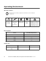
Operating Environment
Operating conditions
Install the UPS in an indoor, temperature-controlled area, free of conductive
contaminants.
Note
Temperature
Range:
32° to 104°F /
0° to 40°C
Keep Ventilated
Front-to-Rear
Airflow (see
space
considerations)
Relative
Humidity: <95%
Non-condensing
No Conductive
Dust or
Corrosive
Fumes
Altitude derating table:
3000ft/914m: 100% load
4500ft/1371m: 95% load
6000ft/1828m: 91% load
8000ft/2438m: 86% load
10000ft/3048m: 82% load
Heat dissipation
UPS size
kW at fully charged batteries
10kVA
0.5
15kVA
0.75
20kVA
1.0
30kVA
1.5
40kVA
2.0
Audible noise
Audible noise at 100% load:
(measured 1.09yard/1m from the
UPS)
20
10-30kVA
20-40kVA
64dBA
67dBA
Smart-UPS® VT 10-40kVA, 400V, Site Preparation and Installation Manual
– 990-1986
Site Preparation (UPS and XR) – Operating Environment
Recommended source connections
The UPS must be supplied from a 400Y/230V 4W + GND 50Hz source.
CAUTION!
Verify clockwise phase-rotation (L1, L2, L3) and make sure a neutral connection is
present.
See also Recommended Wiring for a 104oF (40oC) Temperature Environment.
Smart-UPS® VT 10-40kVA, 400V, Site Preparation and Installation Manual
– 990-1986
21
Site Preparation (UPS and XR) – Operating Environment
Recommended current protection
AC output over-current protection and AC output disconnect must be provided by the
customer.
Note
Dual/
single
mains
configuration
Connection
10kVA
15kVA
20kVA
30kVA
40kVA
Notes
Dual
Mains
input
20A
breaker
(30kA)
35A
breaker
(30kA)
50A
breaker
(30kA)
63A
breaker
(30kA)
80A
breaker
(30kA)
1+2
Dual
Bypass
input
20A
breaker
(30kAIC)
35A
breaker
(30kA)
50A
breaker
(30kA)
63A
breaker
(30kA)
80A
breaker
(30kA)
1+2
Single
Mains/
Bypass
input
20A
breaker
(30kA)
35A
breaker
(30kA)
50A
breaker
(30kA)
63A
breaker
(30kA)
80A
breaker
(30kA)
1+2
Any
Output
20A
Class
gL (gG)
fuse
35A
Class
gL (gG)
fuse
50A
Class
gL (gG)
fuse
63A
Class
gL (gG)
fuse
80A
Class gL
(gG) fuse
3
Note 1:
If the available fault current of the installation is below 30kA, a lower Icu-rated breaker can be used.
Note 2:
For breaker settings, refer to below table listing available overload currents.
Note 3:
Maximum rating of a single fuse configuration if the internal bypass must be protected during a load
short circuit. Selectivity is not ensured by the configuration.
22
Smart-UPS® VT 10-40kVA, 400V, Site Preparation and Installation Manual
– 990-1986
Site Preparation (UPS and XR) – Operating Environment
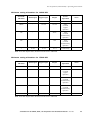
Minimum setting of breakers for 10kVA UPS
Overload/
Duration
Mains input
Bypass input
Output
Event/
Operation
Notes
<10ms
2kA
1.7kA
9kA
Internal fault
1
500ms
-
121.5A
121.5A
800%
overload
bypass
operation
30s
-
-
22.8A
150%
overload
normal/battery
operation
60s
-
-
19A
125%
overload
normal/battery
operation
∞
16.4A
16.7A
16.7A
Continuously
Note 1: For the output value, the short-circuit-level is indicated.
Minimum setting of breakers for 15kVA UPS
Overload/
Duration
Mains input
Bypass input
Output
Event/
Operation
Notes
<10ms
2.1kA
1.8kA
9kA
Internal fault
1
500ms
-
182A
182A
800%
overload
bypass
operation
30s
-
-
34.2A
150%
overload
normal/battery
operation
60s
-
-
25.4A
125%
overload
normal/battery
operation
∞
24.6A
25.1A
25.1A
Continuously
Note 1: For the output value, the short-circuit-level is indicated
Smart-UPS® VT 10-40kVA, 400V, Site Preparation and Installation Manual
– 990-1986
23
Site Preparation (UPS and XR) – Operating Environment
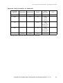
Minimum setting of breakers for 20kVA UPS
Overload/
Duration
Mains input
Bypass input
Output
Event/
Operation
Notes
<10ms
2.5kA
2.3kA
9kA
Internal fault
1
500ms
-
244A
244A
800%
overload
bypass
operation
30s
-
-
45.6A
150%
overload
normal/battery
operation
60s
-
-
38A
125%
overload
normal/battery
operation
∞
32.5A
33.4A
33.4A
Continuously
Note 1: For the output value, the short-circuit-level is indicated.
Minimum setting of breakers for 30kVA UPS
Overload/
Duration
Mains input
Bypass input
Output
Event/
Operation
Notes
<10 ms
3 kA
2.3kA
14 kA
Internal fault
1
500ms
-
365A
365A
800%
overload
bypass
operation
30s
-
-
68.4A
150%
overload
normal/battery
operation
60s
-
-
57A
125%
overload
normal/battery
operation
∞
49.2A
50.1A
50.1A
Continuously
Note 1: For the output value, the short-circuit level is indicated.
24
Smart-UPS® VT 10-40kVA, 400V, Site Preparation and Installation Manual
– 990-1986
Site Preparation (UPS and XR) – Operating Environment
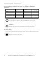
Minimum setting of breakers for 40kVA UPS
Overload/
Duration
Mains input
Bypass input
Output
Event/
Operation
Notes
<10 ms
3 kA
2.3kA
14 kA
Internal fault
1
500ms
-
487A
487A
800%
overload
bypass
operation
30s
-
-
91.2A
150%
overload
normal/battery
operation
60s
-
-
76A
125%
overload
normal/battery
operation
∞
65.6A
66.9A
66.9A
Continuously
Note 1: For the output value, the short-circuit level is indicated.
Smart-UPS® VT 10-40kVA, 400V, Site Preparation and Installation Manual
– 990-1986
25
Site Preparation (UPS and XR) – Operating Environment
Recommended phase-conductor sizes [AWG] for a 86°F (30°C) temperature
environment
UPS/[mm2] sizes
Mains input
[mm2]
AC output
[mm2]
DC input
[mm2] 700C Wire
10kVA
2.5
2.5
6
15kVA
6
6
10
20kVA
10
10
16
30kVA
16
16
35
40kVA
25
25
50
Use Molex lug type or equivalent, and crimp to manufacturer’s specifications.
Note
)
WARNING!
At 100% switch mode load, the neutral shall be rated for 200% phase current.
EPO switch wiring
The UPS must be connected to either a dry contact or a 24VDC Emergency Power Off (EPO) switch.
See EPO wiring options in this manual.
26
Smart-UPS® VT 10-40kVA, 400V, Site Preparation and Installation Manual
– 990-1986
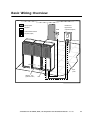
Basic Wiring Overview
AC input power
Maintenance
Bypass Panel
DC power
EPO
Communication Interface
(Optional Equipment)
AC power (output)
Output power
Input
power
XR Enclosure(s)
(Optional, 4 Max.)
UPS
Smart-UPS® VT 10-40kVA, 400V, Site Preparation and Installation Manual
– 990-1986
27
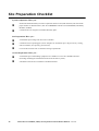
Site Preparation Checklist
System components. Have you –
5
determined minimum battery run time requirement based on load (kW and kVA) and selected the
proper number of XR Enclosures (APC SUVTBXR2B6S and APC SUVTBXR6B6S) and Battery
Modules (SYBT4).
5
considered Service Program or Extended Warranty plan?
Site Preparation. Have you –
5
verified that input voltage and current are available?
5
considered correct operating space, floor strength (see Installation Space Requirements), cooling,
and environment (see Operating Environment).
5
reviewed all electrical work to determine wiring requirements?
Arrival Preparation. Have you –
28
5
verified that space and handling equipment are available to receive the UPS/XR Enclosure?
(Including unloading the UPS/XR Enclosure from the delivery truck ).
5
scheduled an electrician to install the UPS/XR Enclosure?
Smart-UPS® VT 10-40kVA, 400V, Site Preparation and Installation Manual
– 990-1986
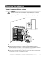
Electrical Installation
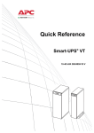
Total-Power-Off Procedure
WARNING!
Hazardous electrically-charged parts inside the UPS and XR Enclosure are energized
from the battery supply even when the AC power is disconnected. Before electrical
installation begins, follow the Total-Power-Off procedure to completely de-energize the
system.
ON
OFF
Mains
breaker
!
Output
Pwr
Zone
Probe
10/100Base-T
Reset
10/100
AP9619 Network
Management Card
EM
Serial:
Model:
BATTERY UNIT
Serial:
Model:
BATTERY UNIT
Serial:
Model:
BATTERY UNIT
Serial:
Model:
BATTERY UNIT
Serial:
Model:
BATTERY UNIT
Serial:
Model:
BATTERY UNIT
Serial:
Model:
BATTERY UNIT
Serial:
Model:
BATTERY UNIT
Serial:
Model:
BATTERY UNIT
Serial:
Model:
BATTERY UNIT
Serial:
Model:
BATTERY UNIT
Serial:
Model:
BATTERY UNIT
Serial:
Model:
BATTERY UNIT
Serial:
Model:
BATTERY UNIT
Serial:
Model:
BATTERY UNIT
Serial:
Model:
BATTERY UNIT
Serial:
Model:
BATTERY UNIT
Serial:
Model:
BATTERY UNIT
Serial:
Model:
BATTERY UNIT
Serial:
Model:
BATTERY UNIT
Serial:
Model:
BATTERY UNIT
Serial:
Model:
BATTERY UNIT
Serial:
Model:
BATTERY UNIT
Serial:
Model:
BATTERY UNIT
Serial:
Model:
BATTERY UNIT
Serial:
Model:
BATTERY UNIT
Serial:
Model:
Serial:
Model:
BATTERY UNIT
Serial:
Model:
BATTERY UNIT
Serial:
Model:
BATTERY UNIT
Serial:
Model:
BATTERY UNIT
Serial:
Model:
BATTERY UNIT
Serial:
Model:
BATTERY UNIT
Serial:
Model:
BATTERY UNIT
BATTERY UNIT
Serial:
Model:
BATTERY UNIT
Serial:
Model:
BATTERY UNIT
Serial:
Model:
BATTERY UNIT
Serial:
Model:
BATTERY UNIT
Serial:
Model:
BATTERY UNIT
Serial:
Model:
BATTERY UNIT
Serial:
Model:
BATTERY UNIT
20in/523mm UPS
XR Enclosure
Set the DC disconnect switch (if available) to the OFF position.
Remove all batteries from the system, or, alternatively, pull out all batteries to the red
disconnect line shown on the battery. To ensure solid stability, do not pull batteries out beyond
the red disconnect line unless completely removing them from the Enclosure.
Set the utility breaker to the OFF or LOCKED-OUT position. If the UPS has dual mains supply,
set both supplies to the OFF or LOCKED-OUT position.
Smart-UPS® VT 10-40kVA, 400V, Site Preparation and Installation Manual
– 990-1986
29
Electrical Installation – Total-Power-Off Procedure
Refer to Seismic Anchoring in the Electrical Installation Manual for instructions on how
to remove Seismic Battery Bracket (if applicable).
WARNING!
Correct lock-out procedures at utility breaker must be followed. If necessary, install a
padlock.
30
Smart-UPS® VT 10-40kVA, 400V, Site Preparation and Installation Manual
– 990-1986
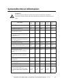
System-Electrical Information
WARNING!
All electrical power and power control wiring must be installed by a qualified
electrician, and must comply with local and national regulations for maximum power
rating.
10kVA
8 kW
15kVA
12 kW
20kVA
16 kW
30kVA
24 kW
40kVA
32kW
Input voltage (V)
3x400/
230V
3x400/
230V
3x400/
230V
3x400/
230V
3x400/
230V
Input current (nominal) (A)
12.4
18.6
24.8
37.2
49.6
Maximum input current (continuous, at
minimum mains voltage)
13.6
20.5
27.3
40.9
54.6
Input current protection for mains source
or single mains supply (external to UPS,
not supplied) (A)
20
35
50
63
80
Input current protection for bypass source
in dual mains configuration (external to
UPS, not supplied) (A)
20
35
50
63
80
Input frequency (Hz) range
40-70
40-70
40-70
40-70
40-70
Output voltage (on line). (V)
Minimum and maximum values (+/- 1%)
3x400/
230V
3x400/
230V
3x400/
230V
3x400/
230V
3x400/
230V
Output current (nominal) (A)
14.4
21.7
28.9
43.3
57.7
Maximum output current
(in bypass only at 110% overload per
phase)
15.9
23.8
31.8
47.6
63.5
Bypass input current (A)
(in bypass only at 110% overload, per
phase)
15.9
23.8
31.8
47.6
63.5
Neutral output current (with 100% switch
mode load) (A)
25.0
37.5
50.0
75.0
100.0
Output current protection (external to
UPS, not supplied) (A)
20
35
35
63
80
Output frequency range (Hz)
50/60
50/60
50/60
50/60
50/60
DC overcurrent device and disconnect
switch for external safety: (A)
DC voltage rating of the battery supply
Maximum available battery supply fault
current
22
33
44
66
88
+/- 192
10 kA
+/- 192
10 kA
+/- 192
10 kA
+/- 192
10 kA
+/- 192
10 kA
UPS ratings
Smart-UPS® VT 10-40kVA, 400V, Site Preparation and Installation Manual
– 990-1986
31
Electrical Installation – System-Electrical Information
Source connections
WARNING!
The UPS must be supplied from a 3x400/230V, L1,L2,L3,N,PE,50Hz source.
CAUTION!
Verify clockwise phase-rotation (L1, L2, L3) and make sure a neutral connection is
present.
For recommended source connections, see The Site Preparation section.
CAUTION!
The installation must comply with all local and national codes.
32
Smart-UPS® VT 10-40kVA, 400V, Site Preparation and Installation Manual
– 990-1986
Wiring
Make sure the UPS is in its location of use before wiring begins.
Note
CAUTION!
Verify clockwise phase-rotation (L1, L2, L3) and make sure a neutral connection is
present.
If seismic protection is required, attach the Seismic Protection Brackets to
the UPS now. Follow step 1 under Seismic Anchoring (Option).
Note
Smart-UPS® VT 10-40kVA, 400V, Site Preparation and Installation Manual
– 990-1986
33
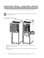
Input/Output Wiring – Single Mains (default)
The UPS is designed for both single (default) and dual mains installations. Carry out the Total Power
Off Procedure, and follow the below steps to install the UPS in a single-mains installation.
The illustrations show a 20in/523 mm Enclosure, but installation procedures are identical for
14in/351mm Enclosures.
Note
Wiring procedure - single mains
N
N
Loosen the (6) M4x13 screws from the cable-land cover plate on the rear, and remove.
Loosen the cable strain relief.
Route the cables from the slanted back plate and up through the punched bracket and into the
cable land area.
34
Smart-UPS® VT 10-40kVA, 400V, Site Preparation and Installation Manual
– 990-1986
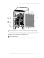
Electrical Installation – Input/Output Wiring – Single Mains (default)
Cable Land
Cover Plate
Neutral
Input
cables
Output
cables
N
L2
L3
L2
Batt+
N
Batt÷
L1
PE cables
N
L1
L3
Attach input cable lugs on L1, L2 and L3 input busbars (left side in the UPS), using the
provided M6 hex screws. Attach output cable lugs on L1, L2 and L3 output busbars, using the
provided M6 hex screws. Attach N x 2 where shown, using the provided hex screws.
Attach PE x 2 where shown, using the provided hex screws.
Fasten the cable strain relief.
Reinstall the Cable Land Cover Plate, following reverse deinstallation procedures.
Smart-UPS® VT 10-40kVA, 400V, Site Preparation and Installation Manual
– 990-1986
35
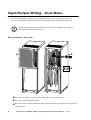
Input/Output Wiring – Dual Mains
The UPS is designed for single mains installation as default. Carry out the Total Power Off
Procedure, and follow the below instructions to install the UPS in a dual-mains installation.
The illustrations show 20in/523 mm Enclosures, but the installation procedures are
identical for 14in/351mm Enclosures.
Note
Wiring procedure - dual mains
C
N
B
N
A
N
Loosen the (6) M4x13 screws from the cable-land cover plate and remove
Loosen the cable attachment bracket.
Route the cables from the slanted back plate and up through the punched bracket and into the
cable land area.
36
Smart-UPS® VT 10-40kVA, 400V, Site Preparation and Installation Manual
– 990-1986
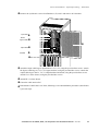
Electrical Installation – Input/Output Wiring – Dual Mains
Remove the (2) M6x12 screws from Brackets A, B, and C and remove all 3 brackets.
Input cables Neutral
Bypass cables L1
L2
L3
N
N
L1
L2
L3
L1
Output cables
L2
L3
Batt+
N
Batt÷
PE cables
Attach the input cable lugs to input busbars L1, L2, L3, using the provided hex screws. Attach
the bypass cable lugs to L1, L2, L3 bypass busbars, using the provided hex screws. Attach the
output cable lugs to the L1, L2, L3 output busbars and attach, using the provided hex screws.
Attach N x 3 where shown, using the provided hex screws.
Attach PE x 3 where shown.
Fasten the cable strain relief.
Reinstall the Cable Land Cover Plate, following reverse deinstallation procedures (described in
a previous step).
Smart-UPS® VT 10-40kVA, 400V, Site Preparation and Installation Manual
– 990-1986
37
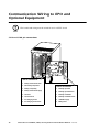
Communication Wiring to EPO and
Optional Equipment
EPO switch and wiring must be suited for use in a SELV circuit.
Note
J106 and J108 pin connections
J106 Pin Connections:
38
1
Battery measurement return
2
Max. battery temperature
J108 Pin Connections:
3
Battery unit quantity
1
Normally open EPO
4
Battery measurement supply
2
Normally open EPO return
5
Q3 active
3
Normally closed EPO
6
Q3 active return
4
Normally closed EPO return
7
Ext. charging control
5
+24V SELV supply
8
Ext. charging control return
6
SELV ground
Smart-UPS® VT 10-40kVA, 400V, Site Preparation and Installation Manual
– 990-1986
Electrical Installation – Communication Wiring to EPO and Optional
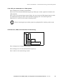
J106 UPS pin connections to J200 options
Pins 1 through 4 are for battery measurement.
Pins 5 & 6 are for external maintenance bypass Q3. When Q3 is closed, signals are fed back to the
UPS controller.
Pins 7 & 8 are for external charge control. When 7 & 8 are closed, the UPS charges batteries with a
pre-defined percentage (0-100%) of the maximum charging power. To be used in generator
applications, or if special codes requires charging control.
When connecting the Q3 auxiliary signal, use gold-plated N/C auxiliary switch on Q3.
Note
XR Enclosure, MBP, and Generator Control wiring
J106
J200 (XR Batteries)
1
1
2
2
3
3
4
4
Q3
switch
5
6
7
8
Charging control switch
Pins 1 through 4 are for battery measurement.
Pins 5 through 6 are for external maintenance bypass Q3.
Pins 7 and 8 are for external charge control.
Smart-UPS® VT 10-40kVA, 400V, Site Preparation and Installation Manual
– 990-1986
39
Electrical Installation – Communication Wiring to EPO and Optional Equipment
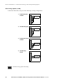
EPO wiring options (J108)
Connect the EPO cable, using one of the following 4 wiring configurations.
1: Dry Normally Open
Contacts
J108
1
2
EPO switch
3
4
5
6
2: +24V Normally Open J108
1
2
EPO switch
3
4
5
6
3: Dry Normally Closed J108
Contacts
1
2
3
4
EPO switch
5
6
4: +24V Normally
Closed
J108
1
2
3
4
EPO switch
5
6
See EPO wiring options for setup.
40
Smart-UPS® VT 10-40kVA, 400V, Site Preparation and Installation Manual
– 990-1986
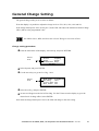
General Charge Setting
The general charge setting is set to 100% as default.
From the display it is possible to adjust the charge levels to 75%, 50%, 25%, 10% and 0%.
If the charge limit input is active (J106, pins 7,8) the UPS will reduce the maximum General Charge
effect (100%) to the programmed value.
See XR Enclosure, MBP, and Generator Control Wiring for overview of J106.
Charge setting procedure
From the main menu of the display, select Set-up, and press RETURN
Selector
Arrow
Control
Status
Setup
Accessories
Logging
Display
Diags
Help
Main Menu
Select System, and press ENTER
Use the arrow keys to get to Gen.Chrg: 100%
Selector
Arrow
Slew rate: 1.00 Hz/s
Gen.Chrg:
100%
Cyclic Chrg. Off
Auto Start: Off
Select Gen.Chrg, and press ENTER
An arrow will appear to the left of Gen.Chrg. Use the UP arrow on the display to go to the
desired level of charge effect. Select ENTER.
Now when the charge limit input is active, the UPS will charge to the new setting.
Smart-UPS® VT 10-40kVA, 400V, Site Preparation and Installation Manual
– 990-1986
41
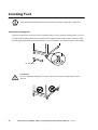
Leveling Feet
Verify that the installation has been electrically wired before setting the leveling feet.
Note
Setting the leveling feet
Set the leveling feet to ensure the UPS is horizontal when it is in its final operating position. Use a 13/
14-mm wrench (shipped with UPS) to adjust all 4 leveling feet from front to back, and left to right,
until the pads make solid contact with the floor. Use a level tube to check the Enclosure is horizontal.
13/14-mm wrench
CAUTION!
To avoid equipment damage, do not move the UPS after the leveling feet have been
lowered.
42
Smart-UPS® VT 10-40kVA, 400V, Site Preparation and Installation Manual
– 990-1986
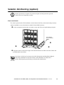
Seismic Anchoring (option)
Seismic protection is an option. If you do not require seismic protection, proceed
to the Front Panel Installation section.
Note
Floor attachment
For seismic protection the UPS installation can be bolted to the floor, and seismic battery brackets
must be installed to secure the batteries in both UPS and XR Enclosures.
Use the 2 transport brackets that were used to secure the UPS to the pallet during transport.
Serial:
Model:
BATTERY UNIT
Serial:
Model:
BATTERY UNIT
Serial:
Model:
BATTERY UNIT
Serial:
Model:
BATTERY UNIT
Serial:
Model:
BATTERY UNIT
Serial:
Model:
BATTERY UNIT
Serial:
Model:
BATTERY UNIT
Serial:
Model:
BATTERY UNIT
Seismic Bracket
(re-use of transport
bracket)
Serial:
Model:
BATTERY UNIT
Serial:
Model:
BATTERY UNIT
Serial:
Model:
BATTERY UNIT
Serial:
Model:
BATTERY UNIT
Align the 4 holes in the bottom angle of the Seismic Bracket on either side of the UPS to the
pre-drilled holes in the floor
See Seismic Anchoring Preparation in the Site Preparation and Installation Manual
and install a minimum of 4 seismic anchors each (minimum size: M8) where
shown, following the specifications provided by the manufacturer.
Smart-UPS® VT 10-40kVA, 400V, Site Preparation and Installation Manual
– 990-1986
43
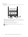
Battery securing
Attach two Seismic Battery Brackets per Battery Module in such a way that one bracket secures two
Battery Units.
Insert the two tabs of the Seismic Battery Bracket into the slots of the two Battery Units.
Push the Seismic Battery Bracket to the right and push it downwards. Align the Seismic Battery
Bracket hole with the hole in the battery shelf.
Use one M6 screw to fasten the Seismic Battery Bracket to the shelf.
Use same procedure to secure all batteries in the Enclosure.
Front Panel
Seismic anchoring procedures identical for both 14in/351mm and 20in/523 mm UPS
Enclosures.
Note
44
Smart-UPS® VT 10-40kVA, 400V, Site Preparation and Installation Manual
– 990-1986
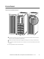
Front Panel
Front Panel installation/removal
To install a Front Panel, insert the two guide taps positioned at the bottom of the Front Panel
into the two slots at the bottom of the Enclosure.
Push the Front Panel forwards until it engages the locking device at the top of the Enclosure.
It is possible to lock the Front Panel: Use a screwdriver to set the lock mechanism to the locked
position.
Use reverse procedures to remove the Front Panel.
Smart-UPS® VT 10-40kVA, 400V, Site Preparation and Installation Manual
– 990-1986
45
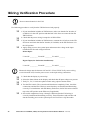
Wiring Verification Procedure
Do not connect batteries in the UPS.
Note
Use following procedure to verify that the UPS has been wired properly:
5
5
5
5
1. If your installation includes an XR Enclosure, make sure that the DC breaker (if
available) is in the OFF position and that both 125A fuses are removed from the
XR Enclosure.
2. Check that the power wiring is torqued to 45 lbf.in/5Nm.
3. If your installation includes an XR Enclosure, remount the 125A fuses in the XR
Enclosure and check that the DC breaker (if available) on the XR Enclosure is in
the ON position.
4. Apply utility power to the system input and measure the voltage at the input
terminal block. Record voltages between:
Mains Input:
L1 and N: _________ L2 and N: ________ L3 and N: _______
Bypass Input (for dual mains installations):
L1 and N: _________ L2 and N: ________ L3 and N: _______
Measured voltage must be between 207 and 253. If not, STOP! Verify correct wiring
(correct location of N) from the power source to the input wiring connections.
Note
5
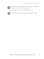
5. Check that the display is powered up.
5
6. Select the Status Menu on the display, and check that all input voltages are present.
5
7. Verify L1, L2, L3 clockwise phase rotation using a phase-rotation meter.
5
8. Test the EPO switch. The system should shut down completely. If not, check the
connections and the EPO switch to ensure that they are installed and functioning
correctly. For installations with XR Battery Enclosures, the DC disconnect should
trip to the OFF position at the EPO test (if applicable).
9. Successful completion of steps 1 through 5 indicates that the UPS wiring is
correctly installed and functioning correctly. Turn off breakers and switches and
shut down utility power to the system input. See Total-Power-Off Procedure.
5
46
Smart-UPS® VT 10-40kVA, 400V, Site Preparation and Installation Manual
– 990-1986
Electrical Installation – Wiring Verification Procedure
If a problem occurs, phone Customer Support at (1) (800) 800-4272 (US and Canada).
Refer to rear cover for contact numbers in other countries.
Note
5 10. Reinstall all wiring access panels and Front Panels to the UPS.
If you have purchased any optional equipment, refer to product-specific manuals.
Note
Smart-UPS® VT 10-40kVA, 400V, Site Preparation and Installation Manual
– 990-1986
47
Installation Site Checklist
This checklist should be completed by the electrician after the wiring has been completed:
Installed at (company name, date, contact)__________________________________________
Name and telephone number of electrician: ___________________________________________
UPS serial number: ______________________________________________________________
Input Circuit Breaker size and type: _________________________________________________
Output fuse size and type: ________________________________________________________
Location of protection devices (room):______________________________________________
Breaker ID: ___________________________________________________________________
EPO type: ____________________________________________________________________
Wire size and type: _____________________________________________________________
PE connection method and location: ________________________________________
48
Smart-UPS® VT 10-40kVA, 400V, Site Preparation and Installation Manual
– 990-1986
LIMITED FACTORY WARRANTY
The limited warranty provided by American Power Conversion Corporation (“APC”) in this
Statement of Limited Factory Warranty applies only to Products you purchase for your commercial or
industrial use in the ordinary course of your business.
APC product covered
Smart-UPS® VT
Terms of warranty
APC warrants that the Product shall be free from defects in materials and workmanship for a period
of one (1) year from the date of start-up when APC authorized service personnel performed the startup of the Product, or a maximum of 18 months from the date of Product shipment from APC, when
APC authorized service personnel have not performed the start-up of the Product (“Warranty
Period”). In the event that the Product fails to meet the foregoing warranty, APC shall repair or
replace any defective parts, such repair or replacement to be without charge for on-site labor and
travel if APC authorized personnel have conducted start-up of the Product. An APC Start-Up Service
must be performed/completed by APC authorized service personnel or replacement of defective parts
only will be covered. APC shall have no liability and no obligation to repair the installed Product if
non-authorized personnel performed the start-up and such start-up caused the Product to be defective.
Any parts furnished under this warranty may be new or factory-remanufactured. Repair or
replacement of a defective product or part thereof does not extend the original warranty
period.
Non-transferable Warranty extends to first purchaser for use
This Warranty is extended to the first person, firm, association or corporation (herein referred to by
“You” or “Your”) for whom the APC Product specified herein has been purchased. This Warranty is
not transferable or assignable without the prior written permission of APC.
Assignment of warranties
APC will assign to you any warranties which are made by manufacturers and suppliers of
components of the APC Product and which are assignable. Any such warranties are assigned “AS IS”
and APC makes no representations as to the effectiveness or extent of such warranties, assumes NO
RESPONSIBILITY for any matters which may be warranted by such manufacturers or suppliers and
extends no coverage under this Warranty to such components.
Smart-UPS® VT 10-40kVA, 400V, Site Preparation and Installation Manual
– 990-1986
49
Drawings, descriptions
APC warrants for the Warranty Period and on the terms of the Warranty set forth herein that the APC
Product will substantially conform to the descriptions contained in the APC Official Published
Specifications or any of the drawings certified and agreed to by an authorized APC representative, if
applicable thereto (“Specifications”). It is understood that the Specifications are not warranties of
performance and not warranties of fitness for a particular purpose.
Warranty claims procedure
To obtain service under Warranty, contact APC Customer Support (see rear cover).You will need the
model number of the Product, the serial number, and the date purchased. A technician will ask you to
describe the problem. If it is determined that the Product will need to be returned to APC you must
obtain a returned material authorization (RMA) number from APC Customer Support. Products that
must be returned must have the RMA number marked on the outside of the package, and be returned
with transportation charges prepaid. If it is determined by APC Customer Support that on-site repair
of the Product is allowed, APC will arrange to have APC authorized service personnel dispatched to
the Product location to repair or replace the Product at the discretion of APC.
Exclusions
APC shall not be liable under the Warranty if its testing and examination discloses that the alleged
defect in the product does not exist or was caused by your or any third person’s misuse, negligence,
improper installation or testing, unauthorized attempts to repair or modify, or any other cause beyond
the range of the intended use, or by accident, fire, lightning or other hazard.
THERE ARE NO WARRANTIES, EXPRESSED OR IMPLIED, BY OPERATION OF LAW
OR OTHERWISE, OF PRODUCTS SOLD, SERVICED OR FURNISHED UNDER THIS
AGREEMENT OR IN CONNECTION HEREWITH. APC DISCLAIMS ALL IMPLIED
WARRANTIES OF MERCHANTABILITY, SATISFACTION AND FITNESS FOR A
PARTICULAR PURPOSE. THE APC EXPRESS WARRANTIES WILL NOT BE
ENLARGED, DIMINISHED, OR AFFECTED BY AND NO OBLIGATION OR LIABILITY
WILL ARISE OUT OF APC RENDERING TECHNICAL OR OTHER ADVICE OR
50
Smart-UPS® VT 10-40kVA, 400V, Site Preparation and Installation Manual
– 990-1986
Electrical Installation – LIMITED FACTORY WARRANTY
SERVICE IN CONNECTION WITH THE PRODUCTS. THE FOREGOING WARRANTIES
AND REMEDIES ARE EXCLUSIVE AND IN LIEU OF ALL OTHER WARRANTIES AND
REMEDIES. THE WARRANTIES SET FORTH ABOVE, CONSTITUTE SOLE LIABILITY
OF APC AND YOUR EXCLUSIVE REMEDY FOR ANY BREACH OF SUCH
WARRANTIES. THE WARRANTIES EXTEND ONLY TO YOU AND ARE NOT
EXTENDED TO ANY THIRD PARTIES.
IN NO EVENT SHALL APC, ITS OFFICERS, DIRECTORS, AFFILIATES OR
EMPLOYEES BE LIABLE FOR ANY FORM OF INDIRECT, SPECIAL,
CONSEQUENTIAL OR PUNITIVE DAMAGES ARISING OUT OF THE USE, SERVICE
OR INSTALLATION OF THE PRODUCTS, WHETHER SUCH DAMAGES ARISE IN
CONTRACT OR TORT, IRRESPECTIVE OF FAULT, NEGLIGENCE OR STRICT
LIABILITY OR WHETHER APC HAS BEEN ADVISED IN ADVANCE OF THE
POSSIBILITY OF SUCH DAMAGE.
Smart-UPS® VT 10-40kVA, 400V, Site Preparation and Installation Manual
– 990-1986
51
APC Worldwide Customer Support
Customer support for this or any other APC product is available at no charge in any of the following ways:
• Visit the APC Web site to access documents in the APC Knowledge Base and to submit customer
support requests.
– www.apc.com (Corporate Headquarters)
Connect to localized APC Web sites for specific countries, each of which provides customer
support information.
– www.apc.com/support/
Global support searching APC Knowledge Base and using e-support.
• Contact an APC Customer Support center by telephone or e-mail.
– Regional centers:
Direct InfraStruXure Customer Support Line
(1)(877)537-0607 (toll free)
APC headquarters U.S., Canada
(1)(800)800-4272 (toll free)
Latin America
(1)(401)789-5735 (USA)
Europe, Middle East, Africa
(353)(91)702000 (Ireland)
Japan
(0) 35434-2021
Australia, New Zealand, South Pacific area
(61) (2) 9955 9366 (Australia)
– Local, country-specific centers: go to www.apc.com/support/contact for contact information.
Contact the APC representative or other distributor from whom you purchased your APC product for
information on how to obtain local customer support.
Entire contents copyright © 2004 American Power Conversion. All rights reserved.
Reproduction in whole or in part without permission is prohibited. APC, the APC logo, and
Smart-UPS VT are trademarks of American Power Conversion Corporation and may be
registered in some jurisdictions. All other trademarks, product names, and corporate names
are the property of their respective owners and are used for informational purposes only.
990-1986
*990-1986*
09/2004