1
POWX093
EN
1
APPLICATION .................................................................................. 3
2
DESCRIPTION (FIG A) .................................................................... 3
3
PACKAGE CONTENT LIST ............................................................. 3
4
SYMBOLS ........................................................................................ 4
5
GENERAL POWER TOOL SAFETY WARNINGS .......................... 4
5.1
Work area ................................................................................................................ 4
5.2
Electrical safety ....................................................................................................... 4
5.3
Personal safety ....................................................................................................... 5
5.4
Power tool use and care ......................................................................................... 5
5.5
Service ..................................................................................................................... 5
6
SPECIFIC SAFETY WARNINGS ..................................................... 5
7
OPERATION ..................................................................................... 6
7.1
Depth Stop............................................................................................................... 6
7.2
Locking lever for cutting machine body ................................................................ 6
7.3
Dust extraction outlet ............................................................................................. 7
7.4
Assembly of parallel stop ....................................................................................... 7
7.5
Inserting and removing the chuck and cutting heads n ....................................... 8
7.6
Cutter guide sleeve ................................................................................................. 8
7.7
Profile accessories ................................................................................................. 9
7.8
Circle cutting accessories ...................................................................................... 9
7.9
Setting the working depth ...................................................................................... 9
7.10
Fine adjustment ...................................................................................................... 9
7.11
Cutting in serval operations ................................................................................... 9
7.12
Switching on and off ............................................................................................. 10
7.13
Adjustable speed .................................................................................................. 10
7.14
Using the parallel guide ........................................................................................ 10
7.15
Cutting direction ................................................................................................... 10
7.16
Replacing the carbon brushes ............................................................................. 10
8
CLEANING AND MAINTENANCE................................................. 11
8.1
Cleaning................................................................................................................. 11
9
TECHNICAL DATA ........................................................................ 11
Copyright © 2015 VARO
P a g e |1
www.varo.com
10
POWX093
EN
NOISE ............................................................................................. 11
11
SERVICE DEPARTMENT .............................................................. 11
12
STORAGE ...................................................................................... 11
13
WARRANTY ................................................................................... 12
14
ENVIRONMENT ............................................................................. 12
15
DECLARATION OF CONFORMITY .............................................. 13
Copyright © 2015 VARO
P a g e |2
www.varo.com
EN
POWX093
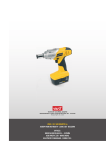
ROUTER
POWX093
1 APPLICATION
Milling of holes, slots, edges and tenors (dovetail joints). All other uses are expressly
excluded.
It is not designed for commercial use.
WARNING! Read this manual and general safety instructions carefully
before using the appliance, for your own safety. Your power tool should
only be passed on together with these instructions.
2 DESCRIPTION (FIG A)
1.
2.
3.
4.
5.
6.
7.
8.
9.
10.
11.
12.
13.
Motor housing.
Fixing screw for depth stop
On/off switch
Carbon brush cover
Spindle lock
Handle
Fixing screw for parallel stop
Depth stop guide
Depth stop scale
Depth stop
Distance scale
Depth stop fixing lever
Culling base
14.
15.
16.
17.
18.
19.
20.
21.
22.
23.
24.
25.
26.
Dust extraction
Parallel stop
Fine adjustment
Cutter guide plate
Wrench
Depth stop setting
Cutter chuck
Circle cutting accessories
Colet chucks
Cutler heads
Speed setting
Adjustment dimension
Safety lock
3 PACKAGE CONTENT LIST
Remove all packing materials
Remove remaining packaging and transit supports (if existing)
Check the completeness of the packing content
Check the appliance, the power cord, the power plug and all accessories for transportation
damages.
Keep the packaging materials as far as possible till the end of the warranty period.
Dispose it into your local waste disposal system afterwards.
WARNING Packing materials are no toys! Children must not play with
plastic bags! Danger of suffocation!
Parallel guide
Circle cutting accessories
Collet chuck
Dust extraction
12 cutting heads
Wrench
Carbon brushes
When parts are missing or damaged, please contact your dealer.
Copyright © 2015 VARO
P a g e |3
www.varo.com
EN
POWX093
4 SYMBOLS
In this manual and/or on the machine the following symbols are used:
Denotes risk of personal injury
or damage to the tool.
Wear ear guards and goggles
Read manual before use
Wear a mask In dusty conditions
In accordance with essential
requirements of the European
directive(s)
"Class II - The machine is
double insulated; Earthing wire
is therefore not necessary
5 GENERAL POWER TOOL SAFETY WARNINGS
Read all safety warnings and all instructions. Failure to follow all warnings and instructions
may result in electric shock, fire and/or serious injury. Save all warnings and instructions for
future reference. The term "power tool" in the warnings refers to your mains operated (corded)
power tool or battery operated (cordless) power tool.
5.1
Work area
Keep work area clean and well lit. Cluttered and dark areas invite accidents.
Do not operate power tools in explosive atmospheres, such as in the presence of
flammable liquids, gases or dust. Power tools create sparks which may ignite the dust or
fumes.
Keep children and bystanders away while operating a power tool. Distractions can cause
you to lose control.
5.2
Electrical safety
Always check that the power supply corresponds to the voltage on the
rating plate.
Power tool plugs must match the outlet. Never modify the plug in any way. Do not use any
adapter plugs with earthed (grounded) power tools. Unmodified plugs and matching
outlets will reduce risk of electric shock.
Avoid body contact with earthed or grounded surfaces such as pipes, radiators, ranges
and refrigerators. There is an increased risk of electric shock if your body is earthed or
grounded.
Do not expose power tools to rain or wet conditions. Water entering a power tool will
increase the risk of electric shock.
Do not abuse the cord. Never use the cord for carrying, pulling or unplugging the power
tool. Keep cord away from heat, oil, sharp edges or moving parts. Damaged or entangled
cords increase the risk of electric shock.
When operating a power tool outdoors, use an extension cord suitable for outdoor use.
Use of a cord suitable for outdoor use reduces the risk of electric shock.
If operating a power tool in a damp location is unavoidable, use a residual current device
(RCD) protected supply. Use of an RCD reduces the risk of electric shock.
Copyright © 2015 VARO
P a g e |4
www.varo.com
EN
POWX093
5.3
Personal safety
Stay alert, watch what you are doing and use common sense when operating a power
tool. Do not use a power tool while you are tired or under the influence of drugs, alcohol or
medication. A moment of inattention while operating power tools may result in serious
personal injury.
Use safety equipment. Always wear eye protection. Safety equipment such as dust mask,
non-skid safety shoes, hard hat, or hearing protection used whenever conditions require
will reduce personal injuries.
Avoid accidental starting. Ensure the switch is in the off position before plugging in.
Carrying power tools with your finger on the switch or plugging in power tools that have
the switch on invites accidents.
Remove any adjusting key or wrench before turning the power tool on. A wrench or a key
left attached to a rotating part of the power tool may result in personal injury.
Do not overreach. Keep proper footing and balance at all times. This enables better
control of the power tool in unexpected situations.
Dress properly. Do not wear loose clothing or jewellery. Keep your hair, clothing and
gloves away from moving parts. Loose clothes, jewellery or long hair can be caught in
moving parts.
If devices are provided for the connection of dust extraction and collection facilities, ensure
these are connected and properly used. Use of these devices can reduce dust related
hazards.
5.4
Power tool use and care
Do not force the power tool. Use the correct power tool for your application. The correct
power tool will do the job better and safer at the rate for which it was designed.
Do not use the power tool if the switch does not turn it on and off. Any power tool that
cannot be controlled with the switch is dangerous and must be repaired.
Disconnect the plug from the power source before making any adjustments, changing
accessories, or storing power tools. Such preventive safety measures reduce the risk of
starting the power tool accidentally.
Store idle power tools out of the reach of children and do not allow persons unfamiliar with
the power tool or these instructions to operate the power tool. Power tools are dangerous
in the hands of untrained users.
Maintain power tools. Check for misalignment or sticking of moving parts, breakage of
parts and any other condition that may affect the power tool’s operation. If damaged, have
the power tool repaired before use. Many accidents are caused by poorly maintained
power tools.
Keep cutting tools sharp and clean. Properly maintained cutting tools with sharp cutting
edges are less likely to stick and are easier to control.
Use the power tool, accessories and tool bits etc., in accordance with these instructions
and in the manner intended for the particular type of power tool, taking into account the
working conditions and the work to be performed. Use of the power tool for operations
different from intended could lead to a hazardous situation.
5.5
Service
Have your power tool serviced by a qualified repair person using only identical
replacement parts. This will ensure that the safety of the power tool is maintained.
6 SPECIFIC SAFETY WARNINGS
Ensure that the power lead does not come into contact with the milling cutter.
Ensure that the lifting rods are firmly seated on the housing and cannot work loose while
working.
Pull out plug before inserting milling cutter.
Copyright © 2015 VARO
P a g e |5
www.varo.com
POWX093
EN
Ensure that milling cutter is firmly clamped.
Use only milling cutters for routers; never use e.g. milling cutters for drilling machines or
stationary machines.
Use only commercially available milling cutters for routers with a shank diameter 6 mm or
8 mm.
Always use both hands to guide the tool.
Never wedge the ON switch fast.
Never reach into the milling zone while the tool is running.
Feed only running milling cutters to the material.
Note direction of cut - always move the cutter against the material.
When work is finished, remove the milling cutter from the tool.
Wood dust set up during work is harmful to health. Always work with dust collector
operating.
Wear protective goggles, ear protectors and, if necessary, breathing mask.
Observe general safety regulations for handling and using electric tools..
7 OPERATION
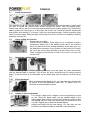
7.1
Depth Stop
Locate the depth stop on the left-hand side of the cutting machine. This continuously
adjustable stop is intended to limit the depth of the cut. Locate the fixing screw for the depth
stop (1). Loosen it by turning it in anticlockwise direction. To move the depth stop up or down,
turn the stop adjuster in clockwise or anticlockwise direction (2).
7.2
Locking lever for cutting machine body
When viewed from the front, the locking lever (3) is located at the rear on the left-hand side.
The cutting machine body is spring-tensioned. Take care when releasing the locking lever.
Grasp both handles and brace yourself before releasing the lever (4). Press downwards to
allow the cutting machine body to move down. When you reduce the downward pressure, the
springs force the cutting machine body back up into its highest position.
CAUTION: The housing of the machine is under spring tension. When you release the locking
lever, it returns to its highest position..
Copyright © 2015 VARO
P a g e |6
www.varo.com
POWX093
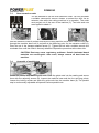
7.3
EN
Dust extraction outlet
You are advised to use the dust extraction outlet. You can purchase
a suitable commercial vacuum cleaner or extract the dust via an
extractor tube while the cutting machine is in operation. The outlet
must project out of the rear of the machine (5). Two bolts and nuts
are supplied to attach it.
Hold the extractor outlet in position and lay the cutting machine on its side. Push the long bolt
through the machine base until it projects at the fastening point for the extractor outlet (6).
Place the nut in the hexagon-shaped recess (7). Tighten the bolt with a suitable wrench and
moderate force until the outlet is securely attached. Repeat the procedure at the other side.
CAUTION: Dust may cause respiratory problems. Certain laminated board
materials are carcinogenic. After work, always remove all dust from the
machine.
7.4
Assembly of parallel stop
Locate the parallel stop and the guide rods. Push the guide rods into the casting and secure
them with the adjusting screws (8). Inspect the machine base and the four securing points.
Loosen the locking screws and push the guide rods into the machine base (9). The parallel
stop is continuously adjustable and permits various parallel cuts.
Copyright © 2015 VARO
P a g e |7
www.varo.com
POWX093
EN
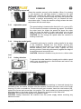
7.5
Inserting and removing the chuck and cutting heads n
The cutting machine is supplied with a set of 12 mm cutting
heads. There are a number of heads for cutting various
profiles in wood. One example is a decorative edge on a
skirting board. The machine is supplied with two chucks for 8
mm and 12 mm. Numerous cutting heads are available for
different profiles.
Some heads are too large and leave no space for the dustextraction system. In this casep a mask should be worn.
CAUTION: Ensure that the machine is not connected to the
power supply. To insert the chuck, locate the spindle lock at
the front of the machine. Press it down and hold it in this
position. Using the wrench provided, loosen the chuck nut by
turning in an anticlockwise direction (10). Remove the chuck
and clean the spindle (11). Insert the other chuck in the
spindle and screw on the nut finger tight. To insert a cutter
head, loosen the chuck nut and insert the shaft of the cutter
head (12). Ensure thai at least 20 mm or halt the length of the
cutter-head shaft is inserted into the chuck. If insertion depth is
less, the cutter head will be instable and may work loose.
Press the spindle lock, hold it in position, and tighten the chuck
nut. Repeatedly check the tightness of the nut during your
work.
CAUTION: Handle the cutter heads carefully. They are sharp
and may cause cuts.
CAUTION: Before switching the machine on, ensure that the
chuck nuts are tight.
7.6
Cutter guide sleeve
The cutter guide sleeve is attached to the base of the
machine and ensures that the machine can follow a certain
cutting profile. Only certain sizes of cutter head can be used.
The si2e is limited by the size of the hole in the cutter guide
sleeve.
The dust-extraction system can be used with this accessory.
To install the guide plate, lay the cutting machine on its side.
Loosen and remove the two bolts for the dust-extraction
system. Remove the four cross-head screws attaching the
plastic base to the casting (13). Note the recess in the plastic
base. Hold the guide plate with the sleeve to the outside and
place it in the recess (14). Align the holes in the plastic base
with the threaded holes in the casting and tighten the four
cross-head screws (15). Re-install the dust-extraction
components and secure it with bolts and nuts.
Copyright © 2015 VARO
P a g e |8
www.varo.com
POWX093
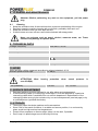
7.7
EN
Profile accessories
The accessories can be used for work on profiled workpieces such as the head of a bed and if
you wish to repeat the outside profile further towards the inside. Take the parallel guide.
Loosen and remove the four cros>head screws attaching the plastic guides (16). Remove the
plastic guides and keep them in a safe place for further use. Locate the profile accessories
and position this casting (17). Secure it with two cross-head screws. Push the parallel guide
into the machine base. Select the right cutter head for this job. Position the workpiece carefully
and begin cutting (18).
7.8
Circle cutting accessories
Accessories for cutting
circles are also supplied. These allow you to cut perfect circles in
workpieces. Attach one of the parallel guide rods in the machine
base (19). Mount the circle-cutting accessory at the other end. You
can attach this accessory to any position on the guide rod. Position
the tip of the circle-cutting accessory at the centre of your circle.
Press it slightly so that the tip is firmly in the wood. You can now
cut the circle.
7.9
Setting the working depth
To set the cutting depth, release the plunger locking lever and press the cutter downwards
until the desired depth is reached. Then re-lock the lever (Locking lever for cutting machine
body). To set the cutter to a fixed depth, set the depth stop (20) and secure it with the knob
(21).
7.10
Fine adjustment
When the approximate depth is set, you can make fine adjustments
by means of the fine-adjustment knob {22). To adjust, turn it in
clockwise or anticlockwise direction.
7.11
Cutting in serval operations
For cutting in depth and in stages, use the length-stop turret as
an aid. Using the depth scale, set the desired depth to the
lowest depth-stop position on the turret. Rotate the turret so that
the highest point is under the depth stop and execute the first
cut (23). Repeat the cut with the second-highest
setting and finally with the last setting. You can also use two
positions if the desired depth is reached in two operations..
Copyright © 2015 VARO
P a g e |9
www.varo.com
POWX093
EN
7.12
Switching on and off
Grasp the machine securely at the handles. When it is pointing
in your direction, the start-stop button is located on the right
handle (24}. Keeping the safety lock pressed, press the startstop button. You do not have to keep the safety lock pressed as
it remains in position automatically until you release the startstop button again. To stop the machine, simply release the startstop button and the motor stops..
7.13
Adjustable speed
The speed setting is located at the front of th e h o usi ng (25).
Turn the knob to increase or decrease the speed. The smaller
the cutter head, the higher the speed.The larger the cutter
head, the lower the speed. A cutter head which runs too fast
causes scorching of the workpiece and leaves burnt marks.
CAUTION: Do not change the speed when the machine is
working under load.
7.14
Using the parallel guide
he parallel guide can be used for cutting parallel to the edge
of the workpiece. Release the four screws securing the
parallel guide and push them in so that the guide is at the
desired distance from the cutter head. Tighten the four
securing screws. Press the guide securely against the edge of
the workpiece and execute the cut.
CAUTION: Abnormal vibrations may be due to a blunt cutter
head.
7.15
Cutting direction
To prevent the cutter head from jumping and to obtain a good
result, carry out exterior cuts in anticlockwise and interior cuts
in clockwise direction (27).
7.16
Replacing the carbon brushes
If the performance of the machine is poor or excessive sparking is observed through the
ventilation slots, the carbon brushes must be replaced. Remove the two covers of the brush
housing (23) with a screwdriver. Remove the two worn brushes. Insert the new brushes (29),
replace the covers and screw them into position. The new brushes may cause sparging until
they have taken on the shape of the motor. Repeat the procedure at the other side.
CAUTION: The brushes must always be replaced in pairs.
CAUTION: Always disconnect the machine from the power supply before removing any
electrical covers.
Copyright © 2015 VARO
P a g e | 10
www.varo.com
EN
POWX093
8 CLEANING AND MAINTENANCE
Attention !Before performing any work on the equipment, pull the power
plug.
8.1
Cleaning
Keep the ventilation slots of the machine clean to prevent overheating of the engine.
Regularly clean the machine housing with a soft cloth, preferably after each use.
Keep the ventilation slots free from dust and dirt.
If the dirt does not come off use a soft cloth moistened with soapy water.
Never use solvents such as petrol, alcohol, ammonia water, etc. These
solvents may damage the plastic parts.
9 TECHNICAL DATA
Voltage / frequency
Power input
No load speed
230~240 V / 50 Hz
1500 W
6000-26000 min-1
12mm
Shaft diameter router
Protection class
II
3m
4,9 kg
Cable
Weight
10 NOISE
Noise emission values measured according to relevant standard. (K=3)
Acoustic pressure level LpA
87 dB(A)
Acoustic power level LwA
98 dB(A)
ATTENTION! Wear
over 85 dB(A).
aw (Vibration)
hearing
protection
6,0 m/s²
when
sound
pressure
is
K = 1,5 m/s²
11 SERVICE DEPARTMENT
Damaged switches must be replaced by our after-sales service department.
If the connecting cable (or mains plug) is damaged, it must be replaced by a particular
connecting cable which is available from our service department. Replacement of the
connecting cable must only be carried out by our service department (see last page) or by
a qualified person (qualified electrician).
12 STORAGE
Thoroughly clean the whole machine and its accessories.
Store it out of the reach of children, in a stable and secure position, in a cool and dry
place, avoid too high and too low temperatures.
Protect it from exposure to direct sunlight. Keep it in the dark, if possible.
Don’t keep it in plastic bags to avoid humidity build-up.
Copyright © 2015 VARO
P a g e | 11
www.varo.com
POWX093
EN
13 WARRANTY
This product is warranted for a 36-month period effective from the date of purchase by the
first user.
This warranty covers all material or production flaws excluding : batteries, chargers,
defective parts subject to normal wear & tear such as bearings, brushes, cables, and
plugs, or accessories such as drills, drill bits, saw blades, etc. ; damage or defects
resulting from maltreatment, accidents or alterations; nor the cost of transportation.
Damage and/or defects resulting from inappropriate use also do not fall under the
warranty provisions.
We also disclaim all liability for any bodily injury resulting from inappropriate use of the
tool.
Repairs may only be carried out by an authorised customer service centre for Powerplus
tools.
You can always obtain more information at the number 00 32 3 292 92 90.
Any transportation costs shall always be borne by the customer, unless agreed otherwise
in writing.
At the same time, no claim can be made on the warranty if the damage of the device is the
result of negligent maintenance or overload.
Definitely excluded from the warranty is damage resulting from fluid permeation, excessive
dust penetration, intentional damage (on purpose or by gross carelessness), inappropriate
usage (use for purposes for which the device is not suitable), incompetent usage (e.g. not
following the instructions given in the manual), inexpert assembly, lightning strike,
erroneus net voltage. This list is not exhaustive.
Acceptance of claims under warranty can never lead to the prolongation of the warranty
period nor commencement of a new warranty period in case of a device replacement.
Devices or parts which are replaced under the warranty therefore remain the property of
Varo NV.
We reserve the right to reject a claim whenever the purchase cannot be verified or when it
is clear that the product has not been properly maintained. (Clean ventilation slots, carbon
brushes serviced regularly, etc.).
Your purchase receipt must be kept as proof of date of purchase.
Your appliance must be returned undismantled to your dealer in an acceptably clean state,
(in its original blow-moulded case if applicable to the unit), accompanied by proof of
purchase.
14 ENVIRONMENT
Should your appliance need replacement after extended use, do not discard it
with the household rubbish but dispose of it in an environmentally safe way.
Waste produced by electrical machine items should not be handled like normal
household rubbish. Please recycle where recycle facilities exist. Check with your
Local Authority or retailer for recycling advice.
Copyright © 2015 VARO
P a g e | 12
www.varo.com
EN
POWX093
15 DECLARATION OF CONFORMITY
VARO N.V. - Joseph Van Instraat 9 - BE2500 Lier - BELGIUM, declares that,
product : Router
trade mark : POWERplus
model : POWX093
is in conformity with the essential requirements and other relevant provisions of the applicable
European Directives, based on the application of European harmonized standards. Any
unauthorized modification of the apparatus voids this declaration.
European Directives (including, if applicable, their amendments up to the date of signature);
2011/65/EU
2004/108/EC
2006/42/EC
European harmonized standards (including, if applicable, their amendments up to the date of
signature);
EN60745-1 : 2009
EN60745-2-17 : 2010
EN55014-1 : 2006
EN55014-2 : 1997
EN61000-3-2 : 2006
EN61000-3-3 : 2013
Keeper of the Technical Documentation : Philippe Vankerkhove, VARO – Vic. Van Rompuy
N.V.
The undersigned acts on behalf of the company CEO,
Hugo Cuypers
Regulatory Affairs – Compliance Manager
Date: 17/03/2015
Copyright © 2015 VARO
P a g e | 13
www.varo.com